1
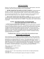
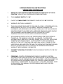
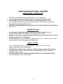
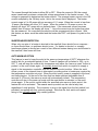
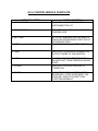
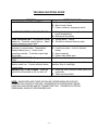
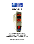
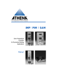
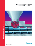
SERIES SSMC TEMPERATURE CONTROL
SYSTEM
USER MANUAL
CONTENTS
Getting Started…………………………………………..……………………………….3
System Operating Instructions………………………………………………………….4
Operating Instructions – Overview……………………………………………………..5
Control Theory – 851-4 Control Module……………………………………………….6
Product Specs – 851-4 Control Module……………………………………………6-10
Auto Warm-up option Instructions…………………………………………………….10
Faceplate Diagram – 851-4 Control Module……………………………………..11-12
Output Connections – 851-4 Control Module………………………………………..13
Troubleshooting Guide…………………………………………………………………14
Service Instructions & Spare Parts List………………………………………………15
Controller Diagram(s)………………………………………………………………16-17
-2-
GETTING STARTED
Because of a great variety in the design of runnerless molds, heated platens, and similar
processes, only broad set-up procedures can be recommended.
1. BEFORE CONNECTING THE CONTROL SYSTEM TO THE MOLD - Re-check and secure
all wiring. Continuity checks should be made as assurance that no heater wires are
shorted to the mold or pinched between plates. Minimum heater insulation resistance to
the mold (cold) should be 500K ohms. Most thermocouples are the grounded junction
type and will normally indicate very low resistance (1-10 ohms) to the mold.
2. BENCH TEST THE MOLD WITH THE CONTROL SYSTEM - Test each zone one at a time.
Initially, test each zone at a reduced operating temperature (200oF). Monitor zone current
with ammeter. Allow mold about an hour to stabilize. Any problems can usually be spotted
in this time.
CAUTION: WHILE BENCH TESTING, A GOOD GROUND WIRE
SHOULD BE CONNECTED AS A SAFETY PRECAUTION.
3. AFTER THE MOLD IS MOUNTED IN THE PRESS - Ensure the proper cable is connected
to its corresponding receptacle at the mold. A well-designed system should incorporate
multiple pin connectors that are keyed and self-locking. This will reduce the total number
of cables and minimize the possibility of improper connections. On hot runner tools,
manifold or runner zones should be brought up to heat first. This should be done slowly,
especially on new molds where accumulated moisture in the heaters may affect their
electrical insulation. Increase temperature settings in 100-200oF increments until final
operating temperatures are reached.
TEMPERATURE CONTROL CARD OPERATING INSTRUCTIONS
SERIES SSMC CONTROLLER
Upon cold start-up (in either warm-up, manual or automatic modes), these temperature
control cards will reverse the polarity of the thermocouple circuit every 40 seconds until a
temperature rise of approximately 40°F is seen. This reversing process will continue for
five minutes and temperature will read ‘LO’ until a temperature rise is seen. Once a
temperature rise is seen, the polarity will automatically stay in the condition the card reads,
either T/C reversed or T/C normal, and the temperature will be displayed. The card will
then regulate temperature regardless of the T/C polarity. If no temperature rise is seen in
five minutes, a shorted thermocouple is assumed and card will read ‘ERR/SHO’.
Other causes of this condition could be:
A. Mis-wired zone
B. Blown fuses or circuit breakers
C. Burned up heater (s)
In the case of B or C, look at amp reading on card and verify no amperage draw when
‘load’ light is on.
In the case of A, check to see that power is going to the proper zone heaters.
-3-
SYSTEM OPERATING INSTRUCTIONS
SERIES SSMC CONTROLLER
1.
BEFORE PLACING THE MAIN POWER DISCONNECT LEVER IN THE “UP” OR ON
POSITION, TURN OFF ALL CONTROLLER POWER SWITCHES.
2.
TURN WARM-UP SWITCH TO “ON”.
3.
PLACE THE “MAIN POWER” DISCONNECT LEVER IN THE “ON” POSITION.
4.
WARM-UP LIGHT WILL ILLUMINATE.
5.
TURN EACH ZONE TO BE USED TO “ON” ONE AT A TIME. IF CONTROLLER IS IN
MANUAL MODE, SWITCH IT TO “AUTOMATIC” MODE BY PRESSING THE
INCREMENT AND DECREMENT KEYS SIMULTANEOUSLY FOR TWO SECONDS.
MONITOR POWER TO HEATERS WITH AMPERAGE READING IN AMPS WINDOW.
USE INCREMENT AND DECREMENT KEYS TO ADJUST SET POINT
TEMPERATURE WHICH IS DISPLAYED IN SETPOINT WINDOW.
6.
WITH WARM-UP SWITCH IN THE “ON” POSITION EACH TIME THE SYSTEM IS
TURNED ON, THE WARM-UP LIGHT WILL ILLUMINATE. THIS FEATURE
AUTOMATICALLY RESTRICTS CONTROL ZONES TO 25% OUTPUT UNTIL ZONE
TEMPERATURE REACHES 250°F. WHEN DESIRED, TURN THE WARM-UP
SWITCH TO THE “OFF” POSITION, THE LIGHT WILL GO OUT. POWER TO THE
HEATERS WILL BE UNRESTRICTED AND THE OPERATING TEMPERATURE WILL
BE THAT AS INDICATED ON THE CONTROLLER TEMPERATURE WINDOW.
WARM-UP TIME IS NORMALLY 20 MINUTES.
7.
TO RESET THE WARM-UP FEATURE, TURN THE WARM-UP SWITCH TO THE “ON”
POSITION.
8.
PROBLEMS - CONTROL PROBLEMS ARE RARELY CAUSED BY CONTROL
SYSTEM FAILURE, AND CAN USUALLY BE TRACED BACK TO MOLD WIRING OR
MISPLACED / FAILED THERMOCOUPLES AND HEATERS. WITH THE EXCEPTION
OF OPERATING IN THE WARM-UP MODE, ALL CONTROL ZONES OPERATE
COMPLETELY INDEPENDENT OF EACH OTHER. A TROUBLE SHOOTING GUIDE
IS PROVIDED IN THIS MANUAL FOR DETERMINING MOLD AND CONTROL
SYSTEM PROBLEMS.
-4-
OPERATING INSTRUCTIONS – OVERVIEW
SERIES SSMC CONTROLLER
1.
2.
3.
4.
TURN ALL POWER SWITCHES ON CARDS TO “OFF” POSITION.
PLACE MAIN POWER DISCONNECT SWITCH ON CONTROLLER TO “ON”.
TURN POWER SWITCH TO “ON” FOR EACH CARD (ZONE) BEING USED.
SET DESIRED TEMPERATURE SETPOINT ON EACH CARD USING THE UP OR
DOWN BUTTONS ON FACE OF CARD.
5. READ ACTUAL TEMPERATURE OF ZONE ON THE UPPER (TEMPERATURE) DISPLAY
ON CARD.
WARM-UP FEATURE
1. PLACE MAIN POWER DISCONNECT SWITCH ON CONTROLLER TO “ON”.
2. TURN WARM-UP ON/OFF SWITCH ON CONTROLLER TO “ON”.
3. WARM-UP LIGHT WILL ILLUMINATE AND ALL ZONES WILL BE RESTRICTED TO 25%
POWER, UNTIL 250o F IS REACHED.
4. WHEN DESIRED, TURN THE WARM-UP SWITCH TO “OFF”. POWER TO ALL ZONES
WILL BE DICTATED BY TEMPERATURE SETPOINT.
MANUAL FEATURE
1. TO PUT CARD IN MANUAL MODE, DEPRESS UP AND DOWN BUTTONS
SIMULTANEOUSLY FOR 2 SECONDS.
2. TEMPERATURE DISPLAY WILL DISPLAY THREE DASHES, AND OUTPUT POWER
CAN BE SELECTED BY PRESSING THE UP OR DOWN BUTTON TO DESIRED
PERCENTAGE (0-100%).
3. TO SWITCH BACK TO AUTOMATIC MODE, DEPRESS UP AND DOWN BUTTONS
SIMULTANEOUSLY FOR 2 SECONDS.
-5-
CONTROL THEORY
MODEL 851- 4 TEMPERATURE CONTROL MODULE
The 851-4 control module is a precise, solid state instrument for automatic or manual
temperature control of electrically heated dies, molds, or other processes requiring
accurate, reliable temperature control.
Input: The 851-4 control module has high impedance input and will function normally with
up to 50’ of thermocouple leads. In normal applications, special shielding of
thermocouple leads is not necessary.
Output: The output of the 851-4 control module is a 10VDC pulse. A time base of
approximately 3 seconds is used. An automatic reset circuit and factory adjustable
proportional band integrate the load demand/error with time and arrive at a pulse output
duration that will hold the heater load temperature constant.
The output pulse is normally used to drive solid state relays, which switch heater loads on
and off. Solid state relays are zero voltage firing devices and extend heater life by limiting
inrush currents. They can stand momentary overloads of up to 600 amps and require no
maintenance.
PRODUCT SPECIFICATIONS FOR P.E.T.S.
851-4 CONTROL MODULE
FACEPLATE
Please see the faceplate drawing on page 11
Indicators
•
•
•
•
•
•
•
Three digits, seven segments LED, actual temperature readout, labeled “Temperature”.
Three digit, seven segment LED, setpoint temperature readout, labeled “setpoint”.
Two digits, seven segments LED, heater current readout, labeled “Amps”.
Alarm LED
Thermocouple reversed LED.
Load status LED
Power status LED.
Controls
•
•
•
Increment key for setting the setpoint temperature and manual mode duty cycle
Decrement key for setting the setpoint temperature and manual mode duty cycle
Power ON/OFF switch
CIRCUIT BOARDS
-6-
The controller consists of two circuit assemblies
1. The display board contains the displays and switches and is mounted to the faceplate.
2. The control board contains all of the control circuitry and power supply.
CONTROL BOARD CIRCUITS
•
Power supply - Converts the 120VAC to the +5VDC required by the circuits.
•
Seven segment display drivers - The seven segment display drivers are used by the
microcontroller to control the seven segment LED displays.
•
Thermocouple interface - The thermocouple interface circuit measures the voltage
produced by the thermocouple, amplifies it, compensates for the cold junction, and
passes the amplified signal to the microcontroller. The microcontroller then
determines the polarity of the thermocouple and swaps the leads using DPDT relay if
the polarity is reversed. The microcontroller uses the thermocouple signal to determine
the manifold temperature and control the heater accordingly. The circuit is designed for
either J or K type thermocouple.
•
Current transformer interface - The current transformer interface converts the AC
waveform produced by the current transformer into a DC voltage that can be measured
by the microcontroller.
•
Digital control circuit - The digital control circuit consists of a microcontroller and its
support devices. The support devices are a watchdog timer/power monitor/reset chip,
EPROM code memory, and a series EEPROM. The microcontroller performs all logic
execution. Temperature control is done using PID control equations in the
microcontroller.
•
Output drivers (for heater solid state relay and discrete LED’s) - The output driver circuit
interfaces the low power microcontroller outputs to devices that require higher current
signals.
•
Alarm output driver - The alarm output circuit is an AC solid state switch controlled by
the microcontroller.
DISPLAY BOARD
The display board is a mounting surface for the seven segment displays. Discrete LED
indicators and control switches are attached electrically to the control board with one multiconductor flexible cable and attached mechanically to the faceplate.
CIRCUIT OPERATIONS
There are four modes of circuit operation: warm-up, temperature control, history PWM, and
manual. A description of each follows.
-7-
Warm-up mode:
In warm-up mode, the output duty cycle of the load is 25% until the temperature becomes
greater than 250oF. When the temperature is above 250oF, the duty cycle becomes 0.
When the temperature falls below 250oF, it changes back to 25%. During warm-up, the
setpoint display shows the present setpoint, the temperature display shows the measured
temperature of the manifold, and the amps display shows the heater current.
Temperature control mode:
In temperature control mode, the setpoint display shows the present setpoint, the
temperature display shows the measured temperature of the manifold, and the amps
display shows the heater current. The setpoint can be changed by pressing either the
increment of decrement keys on the faceplate. The setpoint changes at the rate of
fouro/second. If the key is held for more than three seconds, it begins to change at the rate
of 50o/second. Normally, temperature will be displayed in Fahrenheit. By placing an
optional jumper on the board, the temperature can be displayed in Centigrade. The
controllable temperature range will be from 150 to 999oF.
Five seconds after a setpoint has been changed, but is not changing, the new setpoint
value will be stored in non-volatile memory so that when power is turned OFF, and the
setpoint will be remembered and restored when power is turned ON.
To change to Manual mode, the increment and decrement keys must be pressed
simultaneously for two seconds.
History PWM:
A feature referred to as history PWM causes the controller to automatically switch to
manual mode when an open thermocouple is detected. When an open thermocouple is
detected, the controller switches to manual mode and displays “OPN” in the temperature
display. The duty cycle in manual mode is the last history PWM value recorded in
automatic mode. The history PWM is the last duty cycle that the controller was operating at
in automatic mode when the temperature was within plus or minus 10oF for 10 consecutive
minutes. To return to automatic mode, press both the increment and decrement keys and
hold them for a few seconds.
Manual mode:
In manual mode, the setpoint display show the present percent ON duty cycle of the heater,
the temperature display shows three dashes, and the amps display shows the heater
current. Pressing either the increment or decrement keys on the faceplate can change the
duty cycle. The duty cycle changes at the rate of four percent per second. If the key is held
for more than three seconds, it begins to change at the rate of 10 percent per second.
Five seconds after a duty cycle has been changed, but is not changing, the new duty cycle
value will be stored in non-volatile memory so that when power is turned OFF, and the duty
cycle will be remembered and restored when power is turned ON.
-8-
To change to Temperature Control mode, the increment and decrement keys must be
pressed simultaneously for two seconds.
ALARM
An alarm condition exists when the measured temperature is more than +/ - 40o from
setpoint. During an alarm condition (only possible in temperature control mode), the alarm
indicator LED is turned ON, and the alarm output is turned ON. An alarm condition is reset
when the temperature is sensed to be within +/ - 35o of setpoint.
THERMOCOUPLE CIRCUIT
In a thermocouple circuit, a voltage is developed due to the difference in temperature
between the ends of each wire. In the PETS system, type J thermocouple wire is used.
One end of the thermocouple circuit is attached to the manifold; the other end is attached to
a control cabinet connector. The voltage generated by the thermocouple circuit represents
the temperature difference between the manifold and the terminating point of the J type
wire. Since the thermocouple wire measures the difference in temperature between its
two ends, the temperature of the control cabinet end must be known in order to determine
the temperature at the manifold end.
The reason for the polarity sensitivity in a thermocouple circuit is that the thermocouple
wire is made of two different metals with different thermoelectric characteristics. One wire
develops a voltage across its length due to the temperature difference between its ends.
The other wire, similarly, develops a voltage across its length. The difference between the
voltages developed by the two wires is the thermocouple voltage. It is like connecting two
batteries of different voltage in series and measuring the voltage across the resulting
circuit. Since a voltage is being measured and not a resistance, it has a polarity. When
both ends of a thermocouple circuit are at the same temperature, no voltage exists and the
polarity can not be determined. Once a temperature difference exists, a voltage is
produced by the thermocouple and the polarity can be determined. Sensing the polarity,
the processor can swap the leads by passing the thermocouple signal through a small
latching relay on the control board that reverses the polarity. The latching relay will retain
its state with power OFF, but the microcontroller will save the status of the Reverse TC
indicator LED in non-volatile memory so that is can be restored on power-up.
A shorted thermocouple detect feature causes the controller to shut down and display
“Err” in the temperature display and “Sho” in the setpoint display if a shorted thermocouple
is detected. To reset the error, the controller must be turned off and then back on. A
shorted thermocouple is detected if the temperature reading stays near the ambient
temperature while heating, and the thermocouple reversing relay has switched four times
without seeing the temperature rise. A shorted thermocouple is also detected if the
temperature is measured to be more than 20oF below the setpoint for 20 consecutive
minutes.
CURRENT SENSING
-9-
The current through the heater is either ON or OFF. When the current is ON, the current
sense transformer produces a sinusoidal voltage proportional to the heater current. The
voltage is measured to determine the heater current. The average heater current is the ON
current multiplied by the ON duty cycle - this is the current that is displayed. The heater
current range is 0 to 20 amps with an accuracy of 0.1 amps. When the current is less than
10 amps, the display will show “X.X” amps. When the current is 10 amps or more, the
display will show “XX” amps with no decimal place. If the measured current becomes
greater than 20 amps, the display will show “- -“since the current may be higher than what
can be measured. An overcurrent threshold could be programmed upon request. With
this feature, an alarm would be added and the heater shut OFF until power is cycled on the
board.
SHORTED HEATER DETECTION
When only one wire of a heater is shorted to the manifold, there should be no response no fuses should blow, no problems should occur. If a heater is shorted, or a supply
transformer phase is shorted as a result of two different heaters having one wire shorted to
the manifold, then fuses will blow.
AUTO WARM-UP OPTION
This feature is used to keep the mold at the warm-up temperature of 250o F whenever the
mold is idle for an extended period of time. Power to heaters will be limited to 25%, up to
250 o F, and will keep the mold at this temperature until either the “warm-up reset” button is
pushed, or the mold closes again. A normally closed limit switch is required to supply a
signal to the temperature controller that will indicate the mold position. When the mold
closes, power to the internal timer is interrupted, providing power to heaters as required by
the temperature controller set point. When the mold opens, power is supplied to the timer,
and timing begins. At the end of the time that has been selected (adjustable from 0
seconds to 10 hours), the warm-up mode will automatically initiate. The temperature
controller will stay in the warm-up mode until the reset button is actuated, or the mold
closes again. If the mold is cycled within the specified auto warm-up timer period, this
feature will not be activated. The manual warm-up switch can be used at any time,
regardless of mold position. The connector to plug in the signal from the limit switch (not
provided) is supplied with this optional package. Note that the limit switch will require
wiring in the normally closed (dry contact) position.
- 10 -
851-4 CONTROL MODULE FACEPLATE
OPERATING CONTROL
1) ON/OFF SWITCH
CONTROL FUNCTION
REMOVES LINE POWER FROM THE
INSTRUMENT 220/110
2) TEMPERATURE
INDICATES THE ACTUAL RUNNING ZONE
TEMPERATURE
3) SET POINT
SETS THE TEMPERATURE YOU WISH TO
REACH BY DEPRESSING EITHER THE UP
OR DOWN BUTTON
SHOWS THE ACTUAL AMPERAGE DRAW
4) AMPS
5) LOAD
INDICATES CONTROLLER DEMAND FOR
OUTPUT POWER TO THE HEATERS
6) ALRM
LIGHTS WHEN ZONE TEMPERATURE
DEVIATES 40oF FROM TEMPERATURE SET
POINT
INDICATES CONTROLE MODULE IS
TURNED ON
7) POWER
8) T/C REV
INDICATES IF ZONE HAS BEEN WIRED
BACKWARD. AFTER 40 SECONDS, THE
CARD WILL SWITCH POLARITY AND
FUNCTION NORMALLY
851- 4 OUTPUT CONNECTIONS
TERMINAL NUMBER
1
FUNCTIONS
120V AC LINE INPUT - L1
2
120V AC LINE INPUT - L2
3
RS-485A
4
+10 VDC OUTPUT PULSES
TO SCR MODULES
5
DC COMMON OUTPUT TO
SCR
6
CURRENT TRANSFORMER
SIGNAL GND
7
ALARM OUTPUT L1, 120
VAC 1 AMP. *THIS TERMINAL
MAY BE USED TO DRIVE
RELAYS
8
CURRENT TRANSFORMERS
SIGNAL
9
HEATER INHIBIT CIRCUIT INPUT
10
HEATER INHIBIT CIRCUIT INPUT
11
RS-485-B
NEW CONSTRUCTION / RETRO-FIT
12
120V AC WARM-UP/+12 VDC WARMUP SIGNAL- L2 SIGNAL (ISOLATED)
13
120V AC WARM-UP/OVDC WARM-UP
SIGNAL - L1 SIGNAL (ISOLATED)
14
THERMOCOUPLE (+) INPUT
15
THERMOCOUPLE (-) INPUT
- 13 -
TROUBLE SHOOTING GUIDE
TROUBLE
NO POWER TO CONTROL SYSTEM
PROBABLE CAUSE
A. System not plugged in.
B. Main fuse(s) blown
C. Power connector improperly wired
ALL ZONES CONTROLLING HIGH OR LOW
A. Wrong load or thermocouple cable in
mold receptacle(s)
B. Mold wired incorrectly
A. Wrong heater and/or
B. Pinched or shorted thermocouple
ZONE OVERHEATING – Temperature display
reads low. Controller output light on. Amps
window showing current draw.
ZONE RUNNING COLD – Current window
showing no current draw. Temperature
display reading low (-). Other zones
operating normally. Controller output light
illuminated.
ZONE RUNNING COLD – Temperature reads
“OPN”
ZONE RUNNING COLD – Temperature
display reads low. Current window shows
current draw.
WARM-UP NOT FUNCTIONING – Warm-up
light will not illuminate or will not shut off.
A. Load cable open
B. Load fuses open – look for shorted
heater
C. Open heater(s)
D. Power relay failed open
A. Thermocouple open
A. Wrong thermocouple zone. Look for
another zone to read high.
A. Warm-up timer (located inside panel) set
incorrectly.
B. Warm-up timer failed
NOTE: NEVER REPLACE FUSES OR FAILED POWER MODULES WITHOUT
LOOKING FOR CAUSE OF FAILURE. DANGEROUS VOLTAGES EXIST INSIDE
CONTROL ENCLOSURE AND AT CONNECTOR PINS. TRAINED ELECTRICAL
PERSONNEL SHOULD PERFORM SERVICE.
- 14 -
SERVICE INSTRUCTIONS AND SPARE PARTS
No maintenance is required unless a malfunction is suspected. If a temperature
control module appears to malfunction, it may be switched between zones (power
must be turned off to switch modules back). When replacing solid state relays, check
input and output terminal polarity.
Most apparent problems are a direct result of mold wiring errors and
heater/thermocouple failures. Refer to troubleshooting guide for correction of most
control failure/problems.
RECOMMENDED SPARE PARTS
P.E.T.S. PC0203B 20 Amp Fuse
P.E.T.S. PC0602A Solid State Relay
P.E.T.S. 851-4 Temperature Control Module
- 15 -