1
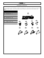
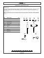
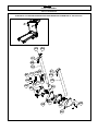
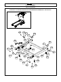
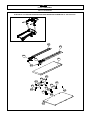
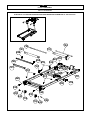
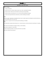
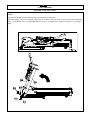
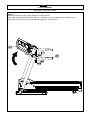
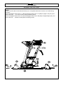
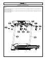
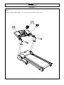
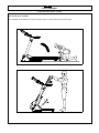
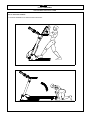
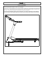
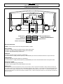
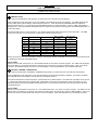
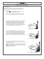
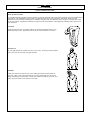
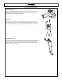
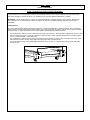
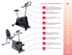
1
Fusion TREADMILL
BEFORE YOU BEGIN
Congratulations for selecting the Fusion Motorized Treadmill from Reebok. Whether you are an accomplished athlete
seeking to maintain peak performance or a beginner realizing the benefits of exercise for the first time, the fusion Motorized
Treadmill will help you to achieve your goals. In the “Hints to Help You” section of this manual we have outlined some tips
that we hope will help you maximize the effectiveness and fun of your workouts.
In the meantime, remember that the benefits of exercise are many and varied including higher energy levels, reduced
stress, improved self-esteem, clearer and more radiant skin, greater cardiovascular efficiency, higher metabolic rate, and
improved body posture – all of which can result in a longer and more enjoyable life.
While purchasing the Fusion Motorized Treadmill will not do all of this alone, it is an important step towards understanding
and achieving the benefits of exercise.
All Reebok products are manufactured to the highest specifications and this
instruction manual should enable you to assemble the Fusion Treadmill and
commence your workout programme. If, however, you have any additional
questions, please call out UK Customer Service on +44 (0) 871 474 2614. To help
us assist you, please quote the product model number and batch number when
calling. The model number is REV-10301. The serial number can be found on a
sticker attached to the Reebok Fusion (located on the left hand side of the treadmill
base next to the mains power cord inlet).
Opening Carton/Assembling Your Product
2
Fusion TREADMILL
CONTENTS
Before you Begin
01
Precautions
03
Contents checklist
04
Hardware Pack
05
Parts List
06
Exploded Diagrams/Part Identification
10
Assembly Instructions
17
Folding instructions
23
Unfolding instructions
24
Level adjustment
25
Computer instructions
26
Motion control operation
32
Operative motion control
33
Helpful hints
34
Stretching routine
35
Training with reebok university
37
How to maintain the fusion treadmill
38
Troubleshooting
40
Ordering replacement parts / limited warranty
41
Warning
Before beginning this or any exercise programme, consul your physician. This is especially important for persons who
have not exercised regularly before or persons with pre-existing health problems. Read all instructions before using.
Reebok® assumes no responsibility for personal injury or property damage sustained by or through the use of this product.
Questions?
As a manufacturer, we are committed to providing complete customer satisfaction. If you have any questions, or if parts
are missing or damaged, we guarantee complete satisfaction.
TO AVOID UNNECESSARY DELAYS, PLEASE CALL OUR CUSTOMER HOTLINE DIRECT. The trained technicians on
our customer hotline will provide immediate assistance free of charge.
UK Customer Hotline: 0871 474 2614
UK Customer Services: RFE International Ltd.; DFDS House, Maidstone Road; Kingston, Milton Keynes MK10 0AJ
UK Email: [email protected]
Caution
Read all precautions and instructions in this manual before using this equipment. Keep this manual for future reference.
Model No: REV-10301
Serial No: for example : REV-10301/1106/000001
Write the serial number and mfr date in the space above for future reference. (Located on the left hand side of the treadmill
base next to the mains power cord inlet.)
3
Fusion TREADMILL
PRECAUTIONS
WARNING: To reduce the risk of burns, fire, electric shock, or injury to persons, read the following important precautions
and information before operating the treadmill.
1.
2.
3.
4.
5.
6.
7.
8.
9.
10.
11.
12.
13.
14.
15.
16.
17.
18.
19.
20.
21.
22.
23.
It is the responsibility of the owner to ensure that all users of this treadmill are adequately informed of all warnings and
precautions.
Use the treadmill only as described in this manual.
Place on a level surface, with 2m of clearance behind it. To protect the floor or carpet from damage, place a mat under
the treadmill.
When choosing a location for the treadmill make sure that the location and position permit access to a plug.
Keep the treadmill indoors, away from moisture or dust. Do not put the treadmill in a garage or covered patio, or near
water.
Do not operate the treadmill where aerosol products are used or where oxygen is being administered.
Keep children under the age of 12 and pets away from the treadmill at all times.
The treadmill should not be used by persons weighing more than 110kg.
Never allow more than one person on the treadmill at a time.
Wear appropriate exercise clothing when using the treadmill. Do not wear loose clothing that could become caught in
the treadmill. Athletic support clothes are recommended for both men and women. Always wear athletic shoes. Never
use the treadmill with bare feet, wearing only stockings, or in sandals.
When connecting the power cord, plug the power cord into an earthed circuit. When replacing the fuse, an ASTA
approved BS 1362 type should be fitted to the fuse carrier. A 13 amp fuse should be used. No other appliance should
be on the same circuit.
If you need an extension cord, use only 14 gauge cord of 1.5m or less in length.
Keep the power cord away from heated surfaces.
Never move the walking belt while the power is turned on. Do not operate the treadmill if the power cord or plug is
damaged, or if the treadmill is not working properly. (See “Troubleshooting” Page 40. If the treadmill is not working
properly.)
Never start the treadmill while you are standing on the walking belt. Stand on the side rails hold the handrails start the
unit at a low speed and then step on to the unit, when comfortable increase the speed to one that you’re comfortable
with..
The treadmill is capable of high speeds. Adjust the speed in small increments to avoid sudden jumps in speed.
The pulse sensor is not a medical device. Various factors, including the user’s movement, may affect the accuracy of
the heart rate readings. The pulse sensor is intended only as an exercise aid in determining heart rate trends in
general.
Never leave the treadmill unattended while it is running. Always remove the safety key when the treadmill is not in use.
Do not attempt to raise, lower, or move the treadmill until it’s properly assembled. (See Page 17 “Assembly” and Page
23 “Folding the Treadmill”)
Do not change the incline of the treadmill by placing objects under the treadmill.
When folding or moving the treadmill make sure the “power fold switch is fully engaged” (See Page 23 “Folding”)
Inspect and tighten all parts of the treadmill regularly. (See page 38 “Maintenance”)
Never drop or insert any object into any opening in/on the treadmill.
4
Fusion TREADMILL
CONTENTS CHECKLIST
Carton contents:
For your convenience, we have identified the contents of the shipping carton. Please check to make sure you have all of the
components before assembly. This chart is provided to help you identify the components used in the assembly of this
product.
No.
Description
Qty.
A
Main Frame Assembly
1
205
Handle Bar Cover - LL
1
206
Handle Bar Cover - LR
1
207
Handle Bar Cover - RL
1
208
Handle Bar Cover - RR
1
305
Upright Low Cover - LL
1
306
Upright Low Cover - LR
1
307
Upright Low Cover - RL
1
308
Upright Low Cover - RR
1
A
205
305
206
306
207
307
208
308
5
Fusion TREADMILL
HARDWARE COMPARISON CHART
Hardware Pack:
The hardware fitting and tools required for assembly are packed in a bag with in the main carton. These are referenced by
a numerical code as outlined in the parts list (page 6). The pack configuration is shown below in order to ease
identification. Please open the bag carefully and place them on a piece of card, as below, to easily identify the parts
before assembly.
NOTE: We suggest that you do not open the hardware pack until you are ready to assemble your FUSION TREADMILL .
When you open the pack, please do so carefully to ensure that the pieces remain in their position by their identification
numbers.
NO.
DESCRIPTION
QTY.
802
∮3.5×16mm Screw
8
804
M8x 18mm Bolt
6
809
∮4×16mm Screw
4
810
M8x 50mm Bolt
2
811
∮8 Washer
8
A
Wrench
1
B
5mm Allen Wrench
1
C
D
Safety Key
Power Cord
804
802
A
809
810
811
B
1
1
C
MILIMETERS
D
6
Fusion TREADMILL
PARTS LIST
Console Assembly
100
101
Overlay
1
FUSION-101
102
Computer Insert
1
FUSION-102
103
Console Plate
1
FUSION-103
106
Console Housing - Upper
1
FUSION-106
107
Console Housing - Bottom
1
FUSION-107
108
Safety Key Base
1
FUSION-108
109
Safety Key
1
FUSION-109
114
EKG Pulse Wire
2
FUSION-114
115
Water Bottle Holder
2
FUSION-115
116
Motion Control Wire
2
FUSION-116
Handle Bar Assembly
200
201
Handle Bar
1
FUSION-201
202
Handle Bar Upright Foam Grip
2
FUSION-202
203
Handle Bar End Cap
2
FUSION-203
204
Hand Pulse Set
2
FUSION-204
205
Handle Bar Cover - LL
1
FUSION-205
206
Handle Bar Cover - LR
1
FUSION-206
207
Handle Bar Cover - RL
1
FUSION-207
208
Handle Bar Cover - RR
1
FUSION-208
209
Plastic Fixing Insert
10
FUSION-209
210
Motion Control Sensor
2
FUSION-210
211
Motion Control Sensor Base
2
FUSION-211
212
Pulse Sensor Bottom Cover
2
FUSION-212
Upright Assembly
300
301
Upright - Left
1
FUSION-301
302
Upright - Right
1
FUSION-302
303
2 Pin Safety Key Box Middle Power Wire
1
FUSION-303
304
7 Pin Computer Wire
1
FUSION-304
305
Upright Low Cover - LL
1
FUSION-305
306
Upright Low Cover - LR
1
FUSION-306
307
Upright Low Cover - RL
1
FUSION-307
308
Upright Low Cover - RR
1
FUSION-308
309
Power Switch Plate Base
1
FUSION-309
310
Power Switch Plate Cover
1
FUSION-310
311
Power Switch
1
FUSION-311
312
Power Breaker
1
FUSION-312
313
Power Switch Plate
1
FUSION-313
7
Fusion TREADMILL
PARTS LIST
Base Frame Assembly
400
401
Base Frame
402
Foot Up Tube
403
Foot Up Lock
405
Spring
407
Caster Holder
408
Rear Wheel
409
Base Frame Cushion
FUSION-401
1
FUSION-402
1
FUSION-403
1
FUSION-405
2
FUSION-407
2
FUSION-408
4
FUSION-409
1
FUSION-501
1
FUSION-502
1
FUSION-503
1
FUSION-504
1
FUSION-505
1
FUSION-506
4
FUSION-507
1
FUSION-508
1
FUSION-509
1
FUSION-511
1
FUSION-512
1
FUSION-513
2
FUSION-514
2
FUSION-515
2
FUSION-516
1
FUSION-517
1
FUSION-518
2
FUSION-519
1
FUSION-601
Motor Assembly
500
501
Motor Hood Top
502
Driving Motor
503
Motor Holder
504
Driving Belt
505
Control Board
506
Elevation Support Tube
507
Elevation Support Tube End Cap
508
Elevation Motor
509
Elevation Gear Sleeve
511
Fold Up Support
512
Wheel
513
Front Shroud
514
Plastic Clamp - Top
515
Plastic Clamp - Bottom
516
Elevation Support
517
Motor Bottom Cover
518
Transfer Board
519
Elevation Support Tube side cover
Running Deck Assembly
600.
601
1
Running Belt
8
Fusion TREADMILL
PARTS LIST
602
Side Rail
2
FUSION-602
603
Running Deck
1
FUSION-603
604
Side Rail End Cap - Left
1
FUSION-604
605
Side Rail End Cap - Right
1
FUSION-605
Deck Frame Assembly
700
701
Deck Frame
1
FUSION-701
702
Front Roller Shaft
1
FUSION-702
703
Front Roller Tube
1
FUSION-703
704
Rear Roller Shaft
1
FUSION-704
705
Rear Roller Tube
1
FUSION-705
706
Running Deck Support Tube
1
FUSION-706
707
Deck Frame - Rear
1
FUSION-707
708
Deck Frame Cross Tube Side Cover
2
FUSION-708
709
Rear Caster
2
FUSION-709
Fastening
800
FUSION-801
801
∮3.5×16mm Screw
8
802
∮4×15mm Screw
37
803
∮3×10mm Screw
2
FUSION-803
804
M8x 18mm Bolt
6
FUSION-804
806
M8x 10mm Bolt
2
FUSION-806
807
∮4 x 80mm Screw
2
FUSION-807
808
∮4 x 55mm Screw
2
FUSION-808
809
∮4×16mm Screw
4
FUSION-809
810
M8x 50mm Bolt
4
FUSION-810
811
∮8Washer
19
FUSION-811
812
M16x 90mm Bolt
2
FUSION-812
813
M4×12mm Screw
3
FUSION-813
814
M8x 45mm Bolt
2
FUSION-814
816
M8 Nut
2
FUSION-816
FUSION-802
9
Fusion TREADMILL
PARTS LIST
824
∮4×19mm Screw
14
FUSION-824
826
∮26 x ∮8.5 x3 Washer
2
FUSION-826
827
Motor Bumper Bushing
1
FUSION-827
828
M8×85mm Fixed Bolt
1
FUSION-828
829
M8x12mm Bolt
2
FUSION-829
830
∮8 Washer
2
FUSION-830
831
M8×47mm Fixed Bolt
1
FUSION-831
833
M10×116mm Hexagon Screw
1
FUSION-833
837
M8x30mm Bolt
4
FUSION-837
838
M10×67mm Bolt
1
FUSION-838
841
Bushing
1
FUSION-841
842
∮6x1 Washer
5
FUSION-842
843
M5×8mm Bolt
1
FUSION-843
845
M5×14mm Screw
4
FUSION-845
847
Side Rail Guider
6
FUSION-847
848
M8×30mmScrew
10
FUSION-848
850
M6×45mm Bolt
3
FUSION-850
852
M10×42mm Bolt
1
FUSION-852
853
Cushion Pad
8
FUSION-853
854
M10 Nylon Nut
1
FUSION-854
855
∮10 Washer
1
FUSION-855
856
M10×30mm Bolt
1
FUSION-856
859
M6×15mm Bolt
2
FUSION-859
860
M4x22mm Screw
2
FUSION-860
861
M3x8mm Screw
2
FUSION-861
862
M4x 38mm Screw
2
FUSION-862
10
Fusion TREADMILL
PARTS DIAGRAM
A MAJORITY OF THE PARTS SHOWN HERE HAVE BEEN PRE-ASSEMBLED AT THE FACTORY.
101
801
102
116
116
801
115
103
114
106
108
107
109
803
802
802
11
Fusion TREADMILL
PARTS DIAGRAM
A MAJORITY OF THE PARTS SHOWN HERE HAVE BEEN PRE-ASSEMBLED AT THE FACTORY.
210
211
201
806 811
807
205
204
808
207 209
809
807
806
809
212
862
202
209
206
204
203
811
808
208
210
212 862
809
211
12
Fusion TREADMILL
PARTS DIAGRAM
A MAJORITY OF THE PARTS SHOWN HERE HAVE BEEN PRE-ASSEMBLED AT THE FACTORY.
303
304
811
804
301
309
311 310
861
860
861
312
313
305
811
804
302
209
802
306
307
802
209
308
13
Fusion TREADMILL
PARTS DIAGRAM
A MAJORITY OF THE PARTS SHOWN HERE HAVE BEEN PRE-ASSEMBLED AT THE FACTORY.
812
810
811
804
811
402
403
804
811
407
810
814 408
409
405
816 811
811
802
812
818
811
407
816
409
401
408
802
409
816
811
802
814
409
802
14
Fusion TREADMILL
PARTS DIAGRAM
A MAJORITY OF THE PARTS SHOWN HERE HAVE BEEN PRE-ASSEMBLED AT THE FACTORY.
802
501
824
802
813
505
824
518
833
841
843
511
816 831
503
826
829 828
827
519
507 506
830 802
507 502
802
514
515
823
513
823
822
504
842
512
816
826
516
838
509
507
515
811
519
811
837
837
508
517
802
15
Fusion TREADMILL
PARTS DIAGRAM
A MAJORITY OF THE PARTS SHOWN HERE HAVE BEEN PRE-ASSEMBLED AT THE FACTORY.
602
602
604
605
601
845
824
824
847
824
824
847 848
847
848
824
847
848
824
847
848
847
848
603
16
Fusion TREADMILL
PARTS DIAGRAM
A MAJORITY OF THE PARTS SHOWN HERE HAVE BEEN PRE-ASSEMBLED AT THE FACTORY.
702
704
703
705
848
848
706
853
842 850
852
708
707
854 853
853
855
853
701
842
856
850
859
850
842
709
842
709 842 859
708
17
Fusion TREADMILL
ASSEMBLY INSTRUCTIONS
Before you Begin
•
Clear your work area.
•
Make sure that you’ve cleared a large enough area in order to assemble the treadmill.
•
Make sure there is nothing in the area that may cause injury during assembly.
•
Make sure there’s enough space for you to move around the treadmill after assembly.
•
Remove all components from the boxes before you start assembling the treadmill.
Tools
Before you begin to assemble your treadmill please look at the hardware diagram and familiarize yourself with the parts you
need to assemble and the tools you’ll need.
Make sure you can get hold of the tools easily when assembling your treadmill.
Note
The treadmill has some parts that are fairly heavy. It may be an idea if you have someone that could help you to assemble
it.
Make sure that the treadmill is not plugged in before you start assembly.
Make sure the treadmill is on a flat surface.
Dispose of all packing material at a recycling center when ever possible.
Retain this manual for future reference.
18
Fusion TREADMILL
ASSEMBLY INSTRUCTIONS
STEP 1:
Remove your treadmill from the carton and place it on the floor in an open area.
Attach the Upright - Left (301) and Upright - Right (302) to the Base Frame and secure in place using two M8x 18mm Bolt
(804), two ∮8 Washer (811), one M8x 50mm Bolt (810) and one 8 Washer (811). Repeat this procedure on the Upright –
Right
19
Fusion TREADMILL
ASSEMBLY INSTRUCTIONS
STEP 2:
Rotate the Handle bar (201) to right position as drawing shown .
Secure with one M 8x18mm bolt (804) and one 8 Washer (811) underneath the left Handle bar (201) ,
And repeat the same procedure for the Right Handlebar as drawing shown . .
20
Fusion TREADMILL
ASSEMBLY INSTRUCTIONS
STEP 3:
NOTE: You will need to raise the base frame (701), and please make sure it locks so as not fall during
assembly ..
Attach the Upright Lower Cover -LL (305) and Upright Lower Cover -LR (306) to Upright –Left (301), and
Secure with Four
3.5 x 16 mm screw (802) as drawing shown.
Attach the Upright Lower Cover -RL (307) and Upright Lower Cover- RR (308) to Upright-Right (302), and
Secure with four 3.5x16mm screw (802) as drawing shown .
21
Fusion TREADMILL
ASSEMBLY INSTRUCTIONS
STEP 4:
Attach the Handle Bar Cover – LL (205) and Handle Bar Cover – LR (206) to Upright - Left (301) using two ∮
4×16mm Screw (809)
Attach the Handle Bar Cover – RL (207) and Handle Bar Cover – RR (208) to Upright - Right (302) using two ∮
4×16mm Screw (809)
22
Fusion TREADMILL
ASSEMBLY
STEP 5:
Attach the Water Bottle Holder(115)to the Console Housing - Upper(106)
115
106
23
Fusion TREADMILL
FOLDING INSTRUCTIONS
How to fold up the treadmill:
Your treadmill can be folded up for space saving storage. To do this follow the instructions here:
24
Fusion TREADMILL
UNFOLDING INSTRUCTIONS
How to unfold the treadmill:
To unfold the treadmill for use follow the instructions here:
25
Fusion TREADMILL
LEVEL ADJUSTMENT
FOLLOW THESE INSTRUCTIONS TO LEVEL YOUR TREADMILL:
An uneven floor or improper stabilizer level can cause the treadmill to wobble during use as well as the incline adjustment to
function incorrectly. Please follow the procedure described below to make sure the treadmill stabilizer is adjusted correctly
prior to use. You may need the assistance of another person to perform this adjustment.
First locate the two adjustable stabilizers under the base frame. Then simply rotate them in or out to adjust the
level of the treadmill. When properly adjusted the treadmill should sit firmly on both stabilizers and all cushions.
26
Fusion TREADMILL
COMPUTER INSTRUCTIONS
COMPUTER INSTRUCTIONS
MODEL NUMBER: LCD5P
27
LCD5P COMPUTER INSTRUCTIONS
COMPUTER OPERATION
G
A B
C
DE
F
START Button
A
B
INCLINE UP/DOWN Buttons
SPEED UP/DOWN Buttons
Display Window
Safety Key
C
D
STOP/ENTER Button
E
F
Motion Control Button
G
BUTTON FUNCTIONS
START – Press to start exercise at initial speed 0.5MPH / 0.8KPH.
STOP / ENTER
a. Press to confirm program and preset function values setting mode.
b. Press to run setting procedure before pressing the START KEY.
c. Press to stop exercise during workout time.
SPEED UP
a. Press to increase exercise speed by 0.1MPH/KPH.
b. Hold the button to rapidly increase speed by 0.5MPH/KMPH per second and release the button to stop the function.
SPEED DOWN
a. Press to decrease exercise speed by 0.1MPH/KPH.
b. Hold the button to rapidly decrease speed by 0.5MPH/KMPH per second and release the button to stop the function.
INCLINE UP / DOWN
a. Press up or down to change incline level.
b. Press to select programs and preset related function value.
SAFETY KEY
The safety key must be inserted into the slot on the console in order to operate the treadmill. Always insert the safety key
and attach the clip to your clothing at your waist before beginning your workout. If you should encounter problems and need
to stop the motor quickly, simply pull on the cord to disengage the safety key from the console. To continue operation first
turn the power switch to off and set the speed controller to stop. Next turn the power switch to on and reinsert the safety key
into the console.
28
LCD5P COMPUTER INSTRUCTIONS
COMPUTER OPERATION
POWER ON
Set the POWER SWITCH, located on the base frame, to ON and insert the SAFETY KEY. The UPPER LCD and LOWER
LCD screens light up all digits and enter the POWER ON mode.
The UPPER LCD SPEED/DISTANCE window shows “0.0” and 6 program LED lights blink individually.
The LOWER LCD shows 0 on all windows.
SLEEP MODE
When the power is ON the computer will automatically enter SLEEP MODE if it is left idle for 3 minutes without receiving any
input. Press any button to return to POWER ON status when the computer is in the SLEEP MODE.
DISPLAY MODE
This feature is designed only for store display purpose. To cancel the SLEEP MODE feature, pull out the safety key, press
and hold the SPEED UP and DOWN buttons, insert the safety key to power on the treadmill. After one short beep sound, the
SLEEP MODE will be cancelled and the LCD will not go off as long as the power switch stays on and the safety key is
inserted properly.
ENGLISH / METRIC CONVERSION
The computer has been preset to calculate and show all information in English (miles, pounds, inches). The computer can be
set to display information in Metric (kilometers, kilograms, centimeters). To do this set the POWER SWITCH, located on the
base frame, to ON. Press and hold the START button. Insert the SAFETY KEY. The computer will sound one short BEEP
and the UPPER LCD will show KM and blink. Press the INCLINE UP/DOWN button to switch between KM and ML. KM
means Metric and ML means English. Press the STOP/ENTER button to confirm the setting and return to POWER ON
status after one long beep sound.
QUICK START
When the treadmill is in POWER ON status, press the START button to activate the QUICK START. The SPEED LCD
counts down 3 seconds with 3 short beeps then starts from 0.5 MPH/0.8 KPH. Press the SPEED UP/DOWN buttons to
adjust the speed. Press the INCLINE UP/DOWN buttons to elevate the treadmill. The TIME, CALORIES and DISTANCE
count up from 0. The PULSE LCD shows P until you hold the hand pulse grip sensors then the PULSE LCD will display the
current pulse during the workout.
STOP/PAUSE
During the workout, press the STOP/ENTER button to PAUSE the treadmill, all workout data will be frozen. Press the
START button to resume the workout and all data will continue counting. If the STOP/ENTER button is pressed twice, the
treadmill will return to POWER ON status and all workout information will return to 0.
COMPUTER PROGRAM OPERATION
To select the program, press the program buttons when the treadmill is in POWER ON status. For the first time user, you
have to set up the user information and assign your USER ID from U 1 to U 9 before the program starts.
SET UP USER INFORMATION
Press any program button on the computer panel. For the first time use of the treadmill, the upper LCD will show a blinking
U1 and the lower LCD will show factory default setting values of user weight, height, age and target heart rate. Press the
INCLINE UP/DOWN buttons to choose the USER ID from U1 to U9 and press the STOP/ENTER button to assign your
user ID.
SET USER GENDER
After assigning your user ID, the gender icon will display on the lower LCD. Press the INCLINE UP/DOWN buttons to switch
between male and female icon then press the STOP/ENTER button to select your gender.
SET USER WEIGHT
After setting the user gender, the lower LCD will display W. The TIME LCD display now shows the blinking factory setting
user weight 150LB/68KG. Press the INCLINE UP/DOWN buttons to adjust the user weight correctly and press
STOP/ENTER to set the user weight.
29
LCD5P COMPUTER INSTRUCTIONS
COMPUTER OPERATION
SET USER HEIGHT
After setting the user weight, the lower LCD will display H. The CALORIES LCD display now shows the blinking factory
setting user height 5’3”/160CM. Press the INCLINE UP/DOWN buttons to adjust the user height correctly and press
STOP/ENTER to set the user height.
SET USER AGE
After setting the user weight, the lower LCD will display A. The INCLINE LEVEL LCD display now shows the blinking factory
setting user age 35. Press the INCLINE UP/DOWN buttons to adjust the user age correctly and press STOP/ENTER to set
the user age.
SET USER TARGET HEART RATE
When you set up the user AGE, please note the user TARGET HEART RATE will be adjusted with the user AGE according
to the factory setting. The factory TARGET HEART RATE setting is based on 85% of the maximum heart rate. The
maximum heart rate is calculated as 220 minus the user age. For age 35, the maximum user heart rate should be 185 and
85% of user heart rate, which is 157. After setting the user age, the lower LCD will show P and the PULSE LCD shows the
blinking factory target heart rate setting. Press the INCLINE UP/DOWN buttons to adjust the user target heart rate properly
for your own physical condition and press the STOP/ENTER button to set the user TARGET HEART RATE.
nd
Now, you have completed the user information set up. For the 2 or other member in the family, please assign a different
user ID. This treadmill can allow set and memorize 9 different user’s information. For the repeat user, after pressing the
program button, please press the INCLINE UP/DOWN buttons to select the USER ID that you assigned previously. Each
time when the treadmill is switched off and switched on again it will enter the select program procedure. The user ID will
show the user ID of the previous user.
OPERATE PROGRAM
After completing the USER INFORMATION SET UP, prior to starting the program you selected, please follow the procedure
to operate the different programs as described below:
P1 MANUAL PROGRAM
If you select the P1 MANUAL program, the upper and lower LCD will show the following:
After completing the user information set up, the SPEED LCD displays the initial speed 2.0MPH/3.2KPH and the PULSE LCD
displays P. TIME, CALORIES AND INCLINE LEVEL all show 0. Press the START button to start the workout. Press the
SPEED UP/DOWN buttons to adjust the speed from 0.5MPH to 10MPH and press the INCLINE UP/DOWN buttons to adjust
the incline level from level 0 to 15. Distance, time, calories all count up from 0.
P2 INTERVAL INCLINE
If you select the P2 INTERVAL INCLINE program, the upper and lower LCD will show the following:
After completing the user information set up, SPEED, CALORIES and PULSE LCD display 0. The TIME display shows
factory setting 24:00 and the blinking workout load level shows 1. Press the INCLINE UP/DOWN buttons to adjust the
workout load level from 1 to 12 then press the STOP/ENTER button to confirm the setting.
Then the blinking TIME LCD displays 24:00. Press the INCLINE UP/DOWN buttons to adjust the total workout time and press
the STOP/ENTER button to confirm the setting.
Press the START button to start the workout. SPEED starts from 2.0MPH/3.2KPH. The TIME counts down from the
set up workout time. The CALORIES and DISTANCE count up from 0. INCLINE LEVEL follows the pre-set chart as
follows:
30
LCD5P COMPUTER INSTRUCTIONS
COMPUTER OPERATION
LEVEL
1
2
3
4
5
6
7
8
9
MIN. LEVEL
0
1
2
3
4
5
6
7
8
MAX. LEVEL
4
5
6
7
8
9
10
11
12
During the workout, press the SPEED UP/DOWN buttons to adjust the speed. Users can overwrite the incline level by
pressing the INCLINE UP/DOWN buttons.
COOL DOWN
After the pre-set TIME counts down to 0, treadmill will start a one minute cool down program. The TIME LCD will display
COOL and blink for 10 seconds and continue counting down 50 seconds at speed 2 MPH/3.2KPH. After a one minute cool
down, the treadmill will stop and return to P2 start display. Press STOP/ENTER to go to POWER ON status.
P3 INTERVAL SPEED
If you select the P3 INTERVAL SPEED program, the upper and lower LCD will show the following:
After completing the user information set up, the SPEED, CALORIES and PULSE LCD display 0. The TIME display shows
factory setting 24:00 and a blinking workout load level shows 1. Press the INCLINE UP/DOWN buttons to adjust the workout
load level from 1 to 12 then press the STOP/ENTER button to confirm the setting. Then the TIME LCD will display a blinking
24:00. Press the INCLINE UP/DOWN buttons to adjust the total workout time and press STOP/ENTER button to confirm the
setting.
Press the START button to start the workout. The SPEED start and change follows the pre-set workout load speed chart as
below. The TIME counts down from the set up workout time. The CALORIES and DISTANCE count up from 0. INCLINE
LEVEL starts from level 0.
LEVEL
1
2
3
4
5
6
7
8
9
MIN. SPEED
1.8
2.0
2.2
2.4
2.6
2.8
3.0
3.2
3.4
MAX. SPEED
3.0
3.4
3.8
4.2
4.6
5.0
5.4
5.8
6.2
During the workout, press the INCLINE UP/DOWN button to adjust the incline level. Users can overwrite the speed by
pressing the SPEED UP/DOWN buttons.
COOL DOWN
After the pre-set TIME counts down to 0, the treadmill will start a one minute cool down program. The TIME LCD will display
COOL and blink for 10 seconds and continue counting down 50 seconds at a speed of 2MPH/3.2KPH. After the one minute
cool down, the treadmill will stop and return to P2 start display. Press STOP/ENTER to go to POWER ON status.
31
LCD5P COMPUTER INSTRUCTIONS
COMPUTER OPERATION
P4 WEIGHT LOSS
If you select the P4 WEIGHT LOSS program, the upper and lower LCD will show the following:
After completing the user information set up, the SPEED, CALORIES and PULSE LCD display 0. The TIME display shows
factory setting 24:00 and the blinking workout load level shows 1. Press the INCLINE UP/DOWN buttons to adjust the
workout load level from 1 to 12 then press the STOP/ENTER button to confirm the setting. Then the TIME LCD displays a
blinking 24:00. Press the INCLINE UP/DOWN buttons to adjust the total workout time and press the STOP/ENTER button to
confirm the setting.
Press the START button to start the workout. The SPEED and INCLINE follow the pre-set workout load chart. The TIME
counts down from the set up workout time. Distance and Calories count up from 0.
LEVEL
MIN. SPEED
MAX. SPEED
1
2
3
4
5
6
7
8
9
1.6
1.8
2.0
2.2
2.4
2.6
2.8
3.0
3.2
2.8
3.0
3.2
3.4
3.6
3.8
4.0
4.2
4.4
MINI. INCLINE
LEVEL
0
0
1
1
2
2
3
3
3
MAX INCLINE
LEVEL
3
4
5
6
7
8
9
10
11
During the workout, users can overwrite the speed by pressing the SPEED UP/DOWN buttons and overwrite the incline level
by pressing the INCLINE UP/DOWN buttons.
COOL DOWN
After the pre-set TIME counts down to 0, the treadmill will start a one minute cool down program. The TIME LCD will display
COOL and blink for 10 seconds and continue counting down 50 seconds at a speed of 2MPH/3.2KPH. After a one minute
cool down, the treadmill will stop and return to P2 start display. Press STOP/ENTER to go to POWER ON status.
P5 5K SELF LEARING / COMPETITION
If you select the P5 5K SELF LEARNING / COMPETITION program, the upper and lower LCD will show the following:
After completing the user information set up, the DISTANCE LCD shows preset distance 3M/5KM. The TIME, CALORIES
and INCLINE LEVEL LCD display 0 and the PULSE LCD display shows P.
Press the START button to start the program. Speed starts from 2.0MPH/3.2KPH. The TIME and CALORIES count up from
0. Incline level follows the factory pre-set profile. DISTANCE counts down from 3ML/5KM. During the workout you can
adjust the speed by pressing the SPEED UP/DOWN buttons and overwrite the INCLINE LEVEL by pressing the INCLINE
UP/DOWN buttons.
COOL DOWN
After the pre-set DISTANCE counts down to 0, the treadmill will start a one minute cool down program. The TIME LCD will
display COOL and blink for 10 seconds and continue counting down 50 seconds at a speed of 2MPH/3.2KPH. After a one
minute cool down, the treadmill will stop and return to P2 start display. Press STOP/ENTER to go to POWER ON status.
32
LCD5P COMPUTER INSTRUCTIONS
MOTION CONTROL OPERATION
P6 HEART RATE CONTROL
If you select the P6 5K HEART RATE CONTROL program, the upper and lower LCD will show the following:
After completing the user information set up, the TIME LCD shows the blinking factory pre-set workout time 60:00. Press the
INCLINE UP/DOWN buttons to adjust the workout time and press the STOP/ENTER button to confirm. Then the upper LCD
shows initial speed 2.0MPH/3.2KPH and the lower LCD shows initial warm up time 3:00.
Press the START button to start the 3 minute WARM UP program. Speed starts from 2.0MPH/3.2KPH and INCLINE LEVEL
starts from level 0. Please keep your hand on the hand pulse grips all the time during this workout in order to monitor your
pulse correctly. During the program, if the heart rate monitor fails to sense the pulse you will see P blinking on the PULSE
LCD. If the heart rate monitor senses the pulse properly you will see the stable heart beat sign on the PULSE LCD and the
correct pulse readout on the PULSE LCD. The computer will sense the user pulse every 30 seconds. During the warm up
program you can press the STOP/ENTER button to pause or stop the program or press the START button to re-start the
program. Other buttons will not react during this warm up process.
During the warm up program if heart rate monitor fails to sense the user’s pulse (The PULSE LCD will display P and blink),
the computer will not change the speed. If heart rate monitor senses the user’s pulse properly and the actual user’s pulse
does not reach 65% of the maximum heart rate ((220-age) x 65%), then speed will increase by 0.5MPH/0.8KPH per 30
seconds. If the actual pulse reaches 65% of the maximum heart rate, the speed will remain unchanged. If the actual pulse
reaches 65% of the maximum heart rate over one minute, then the speed will be maintained the same until the warm up
program finishes.
If the actual user’s pulse fails to reach 65% of the maximum heart rate within the first 3 minutes of warm up, the computer will
continue the second 3 minute warm up program. All workout information continues to count up and the timer counts down
from 3:00. During the second 3 minute warm up, the computer will change the incline level instead of speed. If the heart rate
monitor fails to sense the user’s pulse (The PULSE LCD will display P and blink), the computer will not change the incline
level. If the heart rate monitor senses the user’s pulse properly and the actual user’s pulse does not reach 65% of the
maximum heart rate ((220-age) x 65%), then the incline level will be increased by 1 level per 30 seconds. If the actual pulse
reaches 65% of the maximum heart rate, the incline level will remain unchanged. If the actual pulse reaches 65% of the
maximum heart rate over one minute, then the speed will be maintained the same until the warm up program finishes.
If the actual user’s pulse fails to reach 65% of the maximum heart rate within the second 3 minutes of warm up, the computer
will continue the third 3 minute warm up program. All workout information continues to count up and the timer counts down
from 3:00. During the third 3 minute warm up, both speed and incline remain unchanged regardless of the actual pulse. If
time counts down to 0 and 65% of the max. heart rate still can not be reached, the TIME LCD will show FAIL, and the
program will stop and return to POWER ON status.
After the warm up program (if the actual pulse reaches 65% of the max. heart rate to complete warm up program), the
computer will enter the HEART RATE CONTROL program. TIME counts down from the previous setting. Distance and
Calories will continue counting up from the warm up program. During the HEART RATE CONTROL program, the heart rate
monitor will sensor the actual user’s pulse every 30 seconds. If the actual user’s pulse does not reach 85% of the max. heart
rate, then the incline level will be increased by 1 level every 30 seconds. If the actual user’s pulse reaches 85% of the max.
heart rate, then the treadmill performance will be remained the same. If the actual user’s pulse is above 85% of the
max. heart rate, the incline level will be reduce by 1 level. Speed will remain unchanged until the incline level increase up to
15% or the incline level down to 0%. If the incline level is up to 15% and still 85% of the max. heart rate can not be reached,
then speed will start increasing by 0.5MPH/0.8KPH every 30 seconds. If the incline level is down to 0% and still lower than
85% of the max. heart rate can not be reached, then the speed will lower by 0.5MPH/0.8KPH every 30 seconds.
If the actual user’s pulse reaches above 85% of max. heart rate over 3 minutes, the HEART RATE CONTROL program will
be shut down and the computer will enter the one minute COOL DOWN program.
When the TIME counts down to 0, the HEART RATE CONTROL program is completed, and the computer will enter the one
minute COOL DOWN program.
After the COOL DOWN program, the computer will return to POWER ON status.
The purpose of the HEART RATE CONTROL program is to keep the user’s pulse between 65% of the max. heart rate and
85% of the max. heart rate as to reach the most efficient workout result.
33
LCD5P COMPUTER INSTRUCTIONS
OPERATIVE’ MOTION CONTROL
MOTION CONTROL:
Walking belt speed can be increased, decreased or stopped using the
Motion Control sensors on the handlebars. To do this follow the
instructions below:
1.
Press the
MOTION CONTROL button on the console to
switch the motion control function on and off:
•
•
When the LED light is ON the MOTION CONTROL is active.
When the LED light is OFF the MOTION CONTROL is off.
2.
After switching on the MOTION CONTROL wave your right hand
approximately 6 inches above the motion sensor on the right
handle bar to increase the speed. The sensor will sound one
short BEEP per scan and speed up by 0.1 MPH per BEEP.
Holding your right hand approximately 6 inches above the right
sensor constantly results in the sensor sounding one long BEEP
per second and speeding up by 0.5 MPH per second.
2. Use right sensor to speed up.
3.
Wave you left hand approximately 6 inches above the motion
sensor on the left handle bar to decrease the speed. The sensor
will sound one short BEEP per scan and decrease speed by 0.1
MPH. Holding your left hand approximately 6 inches above the
left sensor constantly results in the sensor sounding one long
BEEP per second and decreasing speed by 0.5 MPH per second.
3. Use left sensor to slow down.
4.
Wave both hands approximately 6 inches above both motion
sensors at the same time. The sensor will sound two short BEEP
sounds then stop the belt.
•
Always switch off the motion control function by pressing the
MOTION CONTROL button on the console before turning
off the power to the treadmill.
4. Use both sensors to stop belt.
34
Fusion TREADMILL
HELPFUL HINTS
Hints to Help You Achieve Your Goals
There are a vast number of benefits to exercising. They include improved sleeping patterns, increased metabolic rate due to
the higher ratio of lean muscle tissue to fat (thereby burning calories even when not working out), improved posture reducing
risk of back pain, denser bone mass reducing risk of osteoporosis, clearer skin and the improved self-esteem that go with all
of these. Do not use weight loss as your only measure of success. Your mirror is a much better indicator than your scales.
Don’t set unrealistic goals at the outset of your exercise programme. This could lead to muscle soreness and de-motivation.
Remember, you’re changing your life, take time to do it properly. Don’t try to immediately change your entire lifestyle to get
fitter. Incremental change is far easier and more sustainable. Don’t try to give up fatty foods, alcohol, late nights and start a
grueling exercise regime all on the same day. Take it one step at a time, ensure the changes you make genuinely become
part of your lifestyle and don’t chastise yourself for backsliding occasionally.
Understand the other elements of your daily life that can help or hinder you in achieving your goals. Nutrition is vitally
important in affecting your general well being with regard to the type of food you eat and when you eat it. Also, there are
many opportunities during your normal day when your current habits could be substituted for healthier practices. Instead of
taking the lift, take the stairs and instead of sitting over a long lunch, take a brisk walk and eat an apple. Even if you only do it
one day of the week it all helps.
For more product and fitness information including Reebok University Workouts, visit our website: www.reebokfitness.co.uk
Heart Rate Training
In the normal course of our everyday lives our bodies use oxygen to convert nutrients from our food intake into energy for
muscle movement and body functions. The amount of energy used is measured in calories. Broadly speaking if we burn
more calories than we consume then our body will require additional fuel and will use calories stored as fat. This will lead to
a reduced ratio of fat to lean muscle tissue in our body composition and a leaner, fitter appearance.
As we exercise, our heart rate has to increase in order to deliver sufficient oxygen to the working muscles. Regular
cardiovascular exercise, such as cycling, results in a stronger heart and lungs that are more efficient at delivering oxygen to
muscles which, in turn, are more efficient at converting calories into energy.
It is however, imperative that you accurately determine the target heart rate within which to train in order that you may
improve your fitness at a safe, comfortable and sustainable level.
Start by determining your approximate Maximum Heart Rate (MHR). This is the fastest your heart can beat, measured in
beats per minute. Whilst there are sophisticated ways to measure MHR, an acceptable approximation can be made using
the following calculation:
Males: Estimated Max MHR = 220 – Age
Females: Estimated Max MHR = 226 – Age
Finally, use the Reebok University Training Pyramid on the next page to determine the level at which you should be
exercising based upon your MHR. This level should be maintained using either the cycle’s heart rate grip sensors or a
Reebok Heart Rate Monitor.
35
Fusion TREADMILL
STRETCHING ROUTINE
Warm up and cool down:
A successful exercise program consists of a warm-up, aerobic exercise, and a cool-down. Warming up is an important part of
your workout, and should begin every session. It prepares your body for more strenuous exercise by heating up and
stretching out your muscles, increasing your circulation and pulse rate, and delivering more oxygen to your muscles. At the
end of your workout, repeat these exercises to reduce sore muscle problems. We suggest the following warm-up and cooldown exercises:
Toe Touch:
Slowly bend forward from your waist, letting your back and shoulders relax as you
stretch toward your toes. Reach down as far as you can and hold for 15 counts.
Shoulder Lift:
Lift your right shoulder up toward your ear for one count. Then lift your left shoulder
up for one count as you lower your right shoulder.
Head Roll:
Rotate your head to the right for one count, feeling the stretch up the left side of
your neck. Next, rotate your head back for one count, stretching your chin to the
ceiling and letting your mouth open. Rotate your head to the left for one count, and
finally, drop your head to your chest for one count.
36
Fusion TREADMILL
STRETCHING ROUTINE
Hamstring Stretch:
Sit with your right leg extended. Rest the sole of your left foot against your right
inner thigh. Stretch toward your toe as far as possible. Hold for 15 counts.
Relax and then repeat with left leg extended.
Side Stretch:
Open your arms to the side and continue lifting them until they are over your
head. Reach your right arm as far upward toward the ceiling as you can for one
count. Feel the stretch up your right side. Repeat this action with your left arm.
Calf-Achilles Stretch:
Lean against a wall with your left leg in front of the right and your arms forward.
Keep your right leg straight and the left foot on the floor; then bend the left leg
and lean forward by moving your hips toward the wall. Hold, and then repeat
on the other side for 15 counts.
37
Fusion TREADMILL
TRAINING WITH REEBOK UNIVERSITY
Training with Reebok University
Established in 1993, Reebok University brings together some of the world’s leading fitness professionals and provides you
with access to the latest research in the health and fitness industry. Reebok University has developed a unique fitness
programme with the Reebok Heart Rate Monitor as its cornerstone - the Reebok University Training Pyramid. Incorporating
all the essential principles of exercise, the training pyramid utilizes four distinct training levels based on varying exercise
intensities as measured by your heart rate.
Using the table below, select the training level that best describes your specific fitness goals. Then refer to the pyramid to
determine the duration as well as the exercise intensity (% of maximum heart rate) of your workout programme.
1.
Active lifestyle
Improve functional capacity • Decrease disease risk
Increase life span • Physical well being
2.
Healthy Heart
Improve cardiovascular health • Lose weight • Increase energy
Decrease blood pressure • Decrease cholesterol
Increase immune function • Decrease stress
3.
Cardio Challenge
Improve cardiovascular health • Increase aerobic
capacity and endurance
4.
Extreme Training Challenge
Improve lactic acid tolerance • Performance gains
Increase anaerobic capacity
As a guide, Reebok University recommend that beginners work out in the Active Lifestyle range for the first eight weeks of
their training. After that you will be able to design your own exercise programme to suit your preferences and objectives.
38
Fusion TREADMILL
HOW TO MAINTAIN THE FUSION TREADMILL
Proper maintenance is very important to ensure your treadmill is always in top working condition. Improper maintenance
could cause damage or shorten the life of your treadmill and exceed the LIMITED WARRANTY coverage.
IMPORTANT: Never use abrasives or solvents to clean the treadmill. To prevent damage to the computer, keep liquids
away and keep it out of direct sunlight. Inspect and tighten all parts of the treadmill regularly. Replace any worn parts
immediately.
Belt Adjustment
The running belt has been adjusted properly by the factory. However transportation, uneven flooring or other unpredicted
reasons could cause the belt to shift off center resulting in the belt rubbing with the plastic side rail or end caps and possibly
causing damage. To adjust the belt back to it’s proper position please follow the directions below:
1.
2.
1.
If your belt tends to walk to the right, rotate the right tension bolt clockwise. We recommend adjustments of 1/4 turn at a
time, and follow with a test. If your belt continues to walk to the right, simply adjust the left belt tension bolt by turning it
1/4 turn counterclockwise. Follow with a test.
If your belt tends to walk to the left, rotate the left tension bolt clockwise 1/4 turn at a time, and follow with a test. If the
belt continues to walk to the left, simply adjust the right tension bolt counterclockwise.
If your belt appears to be loose, simply tighten both bolts evenly 1/4 turn. If it appears tight, simply loosen both bolts
evenly 1/4 turn.
39
Fusion TREADMILL
HOW TO MAINTAIN THE FUSION TREADMILL
Belt and Deck Lubrication
The belt and deck were pre-lubricated in the factory prior to assembly. The factory lubrication usually lasts 60-120 days
depending on the frequency of use. The FUSION TREADMILL comes with a small bottle of lubricant. This is enough to
lubricate your FUSION TREADMILL twice (4 ML). Lift the side of the belt 18 inches/45 cm from the rear roller. Squeeze 1
ML under the left side of the belt and 1 ML under the right side of the belt. Run your FUSION TREADMILL at 5 MPH/8 KMH
for 5-10 minutes before exercising. Please be aware that if you over lubricate your FUSION TREADMILL you will
INVALIDATE YOUR WARRANTY. RFE accepts no liability. The lubricant may be applied whenever sticking occurs but, we
recommend you lubricate the belt and deck every 120 days for normal use (3 days a week,
30-45 minutes per day) and every 60 days for frequent use (more than once a day, 30-45 minutes per workout).
40
Fusion TREADMILL
TROUBLESHOOTING
Troubleshooting
NOTE: Do not touch any internal electric wires without consulting the technical support team.
No display on the Computer LCD, after the power is switched on.
1.
2.
3.
Make sure the power cord has been plugged in properly to the power switch on the base frame and mains power
socket.
Make sure the safety key is inserted properly into the safety key slot on the console. Try pulling it in and out several
times until the LCD lights up.
If there is still no power on the computer, call the technical support team for help.
Computer LCD lights up but the running belt has no movement.
1.
2.
3.
Follow the console operating instructions for the P1 manual programme then press the Start button to see if the belt will
move. The belt should move at 0.8km/hour.
If the belt still does not move, press the Speed Up button and see if the speed LCD window indicates the speed
increasing. If you are still having difficulty please call the technical support team.
If when you press the speed button the speed LCD window indicates the speed increasing, but the belt still does not
move please call the technical support team for help.
Computer LCD does not show the pulse.
1.
2.
First, please press the Start button to start the treadmill. Place both hands on the heat rate contact sensors on the
handlebars. Then check if the LCD shows a blinking heart symbol. If the blinking heart symbol is displayed then the
computer is sensoring your pulse properly. Keep your hands on the sensors until the actual pulse number is displayed
on the LCD.
If when holding the contact sensors on the handlebars the heart symbol is not displayed, please disassemble the
handlebars and check to make sure both sensor wires are assembled correctly. Disconnect and then reconnect them
again. Then try the heart rate contacts again. If they still do not work properly, please call the technical support team
for help.
Contact Number
If you have any other problems please call the following number:
UK TECHNICAL SUPPORT TEAM 0871 474 2614
41
Fusion TREADMILL
ORDERING REPLACEMENT PARTS / LIMITED WARRANTY
How to Order Replacement Parts
If you encounter any problems with the product, or need to order replacement parts, call our UK Customer Service
Department on +44 (0) 871 474 2614. To help us assist you, please be prepared to give us the following information:
The Model Number of the product (REV-10301)
The Name of the product (FUSION TREADMILL)
The Serial Number/Manufacturing Date of the product
The Description of the part(s)
Limited Warranty – UK Only
RFE International Ltd. (RFE), warrants this product to be free from defects in workmanship and material, under normal use
and service conditions, for a period of (2) two years for parts and labor, (10) ten years for the motor (parts only) and lifetime
for the frame from the date of purchase. This warranty extends only to the original purchaser. RFE’s obligation under this
warranty is limited to replacing or repairing, at RFE’s option, the product through one of its authorized service centers. All
repairs for which warranty claims are made must be pre-authorized by RFE. This warranty does not extend to any product
or damage to the product caused by or attributed to freight damage, abuse, misuse, improper or abnormal usage or repairs
not provided by a RFE authorized service centre, products used for commercial or rental purposes, or products used as
store display models. No other warranty beyond that specifically set forth above is authorized by RFE.
RFE is not responsible or liable for indirect, special or consequential damages arising out of or in connection with the use of
performance of the product or damages with respect to any economic loss, loss of property, loss of revenues or profits, loss
of enjoyment or use, costs of removal, installation or other consequential damages of whatsoever nature.
The warranty extended hereunder is in lieu of any and all other warranties and any implied warranties of merchantability or
fitness for a particular purpose is limited in its scope and duration to the terms set forth herein.
This warranty gives you specific legal rights.