1
INSTALLATION
MANUAL
(AIR COOLED)
SPLIT-SYSTEM
AIR CONDITIONERS
MODELS: KEU060, 090, 120 & 180
CONTENTS
GENERAL. . . . . . . . . . . . . . . . . . . . . . . . . . . . . . . . . . . . 4
SAFETY CONSIDERATIONS . . . . . . . . . . . . . . . . . . . . 4
INSPECTION . . . . . . . . . . . . . . . . . . . . . . . . . . . . . . . . . 4
INSTALLATION . . . . . . . . . . . . . . . . . . . . . . . . . . . . . . . 6
MAINTENANCE . . . . . . . . . . . . . . . . . . . . . . . . . . . . . . 26
See the following page for a complete Table of Contents.
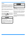
NOTES, CAUTIONS AND WARNINGS
Installer should pay particular attention to the words:
NOTE, CAUTION, and WARNING. Notes are intended to
clarify or make the installation easier. Cautions are given
to prevent equipment damage. Warnings are given to
alert installer that personal injury and/or equipment damage may result if installation procedure is not handled
properly.
CAUTION:
READ ALL SAFETY GUIDES BEFORE YOU
BEGIN TO INSTALL YOUR UNIT.
SAVE THIS MANUAL
157224-YIM-A-0905
157224-YIM-A-0905
TABLE OF CONTENTS
NOMENCLATURE . . . . . . . . . . . . . . . . . . . . . . . . . . 3
GENERAL . . . . . . . . . . . . . . . . . . . . . . . . . . . . . . . . . 4
SAFETY CONSIDERATIONS . . . . . . . . . . . . . . . . . . 4
RENEWAL PARTS . . . . . . . . . . . . . . . . . . . . . . . . . . . . . 4
INSPECTION . . . . . . . . . . . . . . . . . . . . . . . . . . . . . . . 4
INSTALLATION . . . . . . . . . . . . . . . . . . . . . . . . . . . . 6
LIMITATIONS . . . . . . . . . . . . . . . . . . . . . . . . . . . . . . . . . . 6
LOCATION . . . . . . . . . . . . . . . . . . . . . . . . . . . . . . . . . . . . 6
RIGGING AND HANDLING . . . . . . . . . . . . . . . . . . . . . . . 6
CLEARANCES . . . . . . . . . . . . . . . . . . . . . . . . . . . . . . . . . 8
VERTICAL AND HORIZONTAL INSTALLATION - KEU060,
090 AND 120 . . . . . . . . . . . . . . . . . . . . . . . . . . . . . . . . . . . 8
VERTICAL AND HORIZONTAL INSTALLATION KEU180 . . . . . . . . . . . . . . . . . . . . . . . . . . . . . . . . . . . . . . . 8
DUCT CONNECTIONS . . . . . . . . . . . . . . . . . . . . . . . . . . . 9
DRAIN CONNECTION . . . . . . . . . . . . . . . . . . . . . . . . . . 11
REFRIGERANT MAINS . . . . . . . . . . . . . . . . . . . . . . . . . 11
INSTALLING REFRIGERANT MAINS . . . . . . . . . . . . . 11
EXPANSION VALVE BULB . . . . . . . . . . . . . . . . . . . . . 12
POWER AND CONTROL WIRING . . . . . . . . . . . . . . . . . 13
POWER WIRING . . . . . . . . . . . . . . . . . . . . . . . . . . . . . 13
CONTROL WIRING . . . . . . . . . . . . . . . . . . . . . . . . . . . . 13
SUPPLY AIR BLOWER ADJUSTMENT . . . . . . . . . . . . . 15
ACCESSORIES . . . . . . . . . . . . . . . . . . . . . . . . . . . . . . . 25
9
RETURN AIR GRILL ACCESSORY . . . . . . . . . . . . . 10
10
RECOMMENDED DRAIN PIPING . . . . . . . . . . . . . . 11
11
TYPICAL FIELD WIRING . . . . . . . . . . . . . . . . . . . . . 12
12
TYPICAL MOTOR MOUNTING ASSEMBLY . . . . . . 16
13
HOLE LOCATIONS (PRESSURE DROP
READINGS) . . . . . . . . . . . . . . . . . . . . . . . . . . . . . . . 16
14
PRESSURE DROP ACROSS A DRY EVAPORATOR
COIL VS. SUPPLY AIR CFM . . . . . . . . . . . . . . . . . . 17
15
UNIT DIMENSIONS KEU060 . . . . . . . . . . . . . . . . . . 23
16
UNIT DIMENSIONS KEU090 & 120 . . . . . . . . . . . . . 24
17
UNIT DIMENSIONS KEU180 . . . . . . . . . . . . . . . . . . 25
LIST OF TABLES
Tbl. #
Pg. #
1
KEU PHYSICAL DATA . . . . . . . . . . . . . . . . . . . . . . . . 5
2
UNIT VOLTAGE LIMITATIONS . . . . . . . . . . . . . . . . . 5
3
UNIT SUPPLY AIR LIMITATIONS . . . . . . . . . . . . . . . 5
4
UNIT TEMPERATURE LIMITATIONS . . . . . . . . . . . . 5
5
UNIT SUSPENSION MOUNTING (HORIZONTAL
APPLICATION) WEIGHTS . . . . . . . . . . . . . . . . . . . . . 7
6
KEU OPERATING WEIGHTS (LBS.) . . . . . . . . . . . . . 7
MAINTENANCE . . . . . . . . . . . . . . . . . . . . . . . . . . . 26
7
KEU ELECTRICAL DATA . . . . . . . . . . . . . . . . . . . . . 14
EVAPORATOR COIL . . . . . . . . . . . . . . . . . . . . . . . . . . . 26
FILTERS . . . . . . . . . . . . . . . . . . . . . . . . . . . . . . . . . . . . . 26
DRAIN PAN . . . . . . . . . . . . . . . . . . . . . . . . . . . . . . . . . . . 26
LUBRICATION . . . . . . . . . . . . . . . . . . . . . . . . . . . . . . . . 26
BELTS . . . . . . . . . . . . . . . . . . . . . . . . . . . . . . . . . . . . . . . 26
8
SUPPLY AIR BLOWER MOTOR PULLEY
ADJUSTMENT . . . . . . . . . . . . . . . . . . . . . . . . . . . . . 16
9
BLOWER MOTOR AND DRIVE DATA . . . . . . . . . . . 17
10
KEU060 (5 TON) BELT DRIVE BLOWER
PERFORMANCE . . . . . . . . . . . . . . . . . . . . . . . . . . . 18
11
KEU090 (7.5 TON) BELT DRIVE BLOWER
PERFORMANCE . . . . . . . . . . . . . . . . . . . . . . . . . . . 19
12
KEU120 (10 TON) BELT DRIVE BLOWER
PERFORMANCE . . . . . . . . . . . . . . . . . . . . . . . . . . . 20
13
KEU180 (15 TON) BELT DRIVE BLOWER
PERFORMANCE . . . . . . . . . . . . . . . . . . . . . . . . . . . 21
LIST OF FIGURES
Fig. #
Pg. #
1
SUSPENSION MOUNTING (HORIZONTAL) - KEU060,
090 AND 120 . . . . . . . . . . . . . . . . . . . . . . . . . . . . . . . . 6
2
SUSPENSION ACCESSORY (HORIZONTAL) KEU180 . . . . . . . . . . . . . . . . . . . . . . . . . . . . . . . . . . . . 7
3
VERTICAL AND HORIZONTAL APPLICATION
KEU060, 090 AND 120 . . . . . . . . . . . . . . . . . . . . . . . . 8
14
KEU060-120 STATIC RESISTANCE FOR UNIT
ACCESSORIES (IWG) . . . . . . . . . . . . . . . . . . . . . . . 22
4
VERTICAL AND HORIZONTAL APPLICATION
KEU180 . . . . . . . . . . . . . . . . . . . . . . . . . . . . . . . . . . . . 9
15
KEU180 STATIC RESISTANCE FOR UNIT
ACCESSORIES (IWG) . . . . . . . . . . . . . . . . . . . . . . . 22
5
SUPPLY AIR DUCT CONNECTIONS . . . . . . . . . . . . . 9
16
UNIT CLEARANCES KEU060 . . . . . . . . . . . . . . . . . 23
6
ELECTRIC HEAT ACCESSORY . . . . . . . . . . . . . . . 10
17
UNIT CLEARANCES KEU090 & 120 . . . . . . . . . . . . 24
7
SUPPLY AIR PLENUM ACCESSORY . . . . . . . . . . . 10
8
BASE ACCESSORY . . . . . . . . . . . . . . . . . . . . . . . . . 10
18
UNIT CLEARANCES KEU180 . . . . . . . . . . . . . . . . . 25
2
Unitary Products Group
157224-YIM-A-0905
NOMENCLATURE
<RUN,QGRRU6SOLW6\VWHP3URGXFW1RPHQFODWXUH
. (8 $ 3URGXFW&DWHJRU\
. $LU+DQGOHU6SOLW6\VWHP$&
9ROWDJH&RGH
3URGXFW*HQHUDWLRQ
)RXUWK*HQHUDWLRQ
3URGXFW,GHQWLILHU
(8 56WDQG(II3LSH
+HDW7\SH1RPLQDO+HDW&DSDFLW\
$ &RROLQJ2QO\6XLWDEOHIRUILHOGLQVWDOOHGHOHFWULFKHDW
1RPLQDO&RROLQJ
&DSDFLW\0%+
7RQ
7RQ
7RQ
7RQ
Unitary Products Group
3
157224-YIM-A-0905
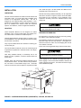
GENERAL
These completely assembled 5, 7-1/2, 10 and 15 ton blower
units include a well insulated cabinet, a DX cooling coil with
copper tubes and aluminum fins, an expansion valve, a distributor, throwaway filters, a centrifugal blower, a blower
motor contactor and a small holding charge of refrigerant-22.
Blower motors and adjustable drives are factory-installed on
all units.
This product must be installed in strict compliance
with the enclosed installation instructions and any
applicable local, state, and national codes including
but not limited to, building, electrical and mechanical
codes.
RENEWAL PARTS
The units are shipped in the vertical position ready for field
installation. For horizontal installation, reverse the solid bottom panel and the return air duct flange on the front of the
unit.
Refer to Parts Manual for complete listing of replacement
parts on this equipment for complete listing of replacement
parts.
SAFETY CONSIDERATIONS
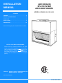
This instruction covers the installation and operation of evaporator blower units. For information on the operation of the
matching condensing unit, refer to Forms 550.46-N1Y,
550.46-N2Y, 550.38-N1Y, 550.38-N6Y AND 550.23-N1Y.
Installer should pay particular attention to the words: NOTE,
CAUTION, and WARNING. Notes are intended to clarify or
make the installation easier. Cautions are given to prevent
equipment damage. Warnings are given to alert installer that
personal injury and/or equipment damage may result if installation procedure is not handled properly.
INSPECTION
As soon as a unit is received, it should be inspected for possible damage during transit. If damage is evident, the extent of
the damage should be noted on the carrier's freight bill. A
separate request for inspection by the carrier's agent should
be made in writing.
Improper installation may create a condition where
the operation of the product could cause personal
injury or property damage.
Improper installation, adjustment, alteration, service
or maintenance can cause injury or property damage. Refer to this manual for assistance or additional information, consult a qualified installer or
service agency.
4
Unitary Products Group
157224-YIM-A-0905
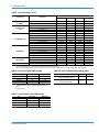
TABLE 1: KEU PHYSICAL DATA
Model
Component
EVAPORATOR
BLOWER1
Description
060
090
120
180
Centrifugal Blower (Dia. X Wd. in.)
15 X 15
15 X 15
15 X 15
18 X 18
Fan Motor HP (Belt Drive)
3/4
1-1/2
2
3
Rows Deep
3
3
3
3
Finned Length (in.)
30
46
46
54
EVAPORATOR
COIL
HOT WATER COIL
STEAM COIL
AIR FILTERS
13
13
13
13
5.0
8.6
10.2
12.1
Rows Deep
2
2
2
2
Finned Length (in.)
30
46
46
54
Fins Per Inch
12
12
12
12
Face Area (ft.2)
3.8
5.4
5.4
9.0
Inlet Connection
1” NPTE
1” NPTE
1” NPTE
1-3/8” O.D
Outlet Connection
1” NPTE
1” NPTE
1” NPTE
1-3/8” O.D
Rows Deep
1
1
1
1
Finned Length (in.)
30
46
46
54
Fins Per Inch
8
8
8
8
Face Area (ft.2)
3.8
5.4
5.4
9.0
Inlet Connection
1-1/2” NPTE
1-1/2” NPTE
1-1/2” NPTE
1-1/2” NPTE
Outlet Connection
1-1/2” NPTE
1-1/2” NPTE
1-1/2” NPTE
1-1/2” NPTE
Quantity Per Unit (16” X 25” X 1”)
2
4
4
0
Quantity Per Unit (20” X 20” X 1”)
0
0
0
6
Total Face Area (ft.2)
5.6
11.1
11.1
16.7
Refrigerant 22 (lbs./oz.)
0/7
0/7
0/10
0/0
HOLDING CHARGE
1.
Fins per Inch
Face Area (ft.2)
Refer to Blower Motor and Drive Data table for additional blower and drive information.
All of these 1750 RPM motors are solid base, 56 frame with 1.15 service factor, inherent protection and permanently lubricated ball bearings.
TABLE 2: UNIT VOLTAGE LIMITATIONS
TABLE 4: UNIT TEMPERATURE LIMITATIONS
Power Rating1
Minimum
Maximum
Temperature
Minimum
Maximum
208/230-1-602
187
252
208/230-3-60
187
252
Wet Bulb Temperature (°F)
of Air on Evaporator Coil
57
72
460-3-60
432
504
77
540
630
Dry Bulb Temperature (°F)
of Air on Heating Coil
40
575-3-60
1.
Utilization Range “A” in accordance with ARI Standard
110.
2.
5 Ton unit only.
TABLE 3: UNIT SUPPLY AIR LIMITATIONS
Unit
Minimum
Maximum
K*EU060
1500
2500
K*EU090
2250
3750
K*EU120
3000
5000
K*EU180
4500
7500
Unitary Products Group
5
157224-YIM-A-0905
INSTALLATION
nuts. Refer to Figure 1 for their location and Table 5 for the
individual load on each hanger rod.
LIMITATIONS
This unit must be installed in accordance with all national and
local safety codes. If no local codes apply, installation must
conform to the appropriate national code. The unit is
designed to meet National Safety Code Standards. If components are to be added to a unit to meet local codes, they
are to be installed at the dealer's and/or the customer's
expense. See Tables 2, 3 and 4 for application limitations.
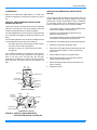
KEU180 units being installed horizontally can be suspended
from above as shown in Figure 2. Refer to From 035-16622001-A-0202 for more information on the installation of the
suspension accessory and for the individual load on each
hanger rod.
Be careful when attaching the hanger rods. They
must not be allowed to turn or slip.
LOCATION
These Evaporator Blowers are not designed for outdoor
installation. They must be located within the building structure, either inside or outside the conditioned space.
These Evaporator Blower sections allow for vertical or horizontal installation in any area offering proper electrical supply,
duct and drain connections.
They may be installed either with ductwork or matching plenum and inlet grill.
RIGGING AND HANDLING
Be careful when moving the unit. Do not remove any packaging until the unit is near its final location.
The packaging consists of a bottom wooden skid that can be
lifted with a fork truck from any direction, a corrugated container that covers the entire unit, and strapping that secures
the container to the skid.
These units can be rigged with slings under the bottom skid.
The units should be located as close to the condensing units
as practical and positioned to minimize bends in the refrigerant piping.
Spreader bars should be used to prevent the slings
from crushing the unit panels and frame.
Units being installed vertically or horizontally can be set
directly on a floor or platform, or metal or wooden beams can
support them.
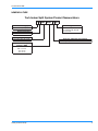
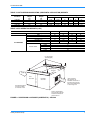
KEU060, 090 & 120 units being installed horizontally can be
suspended from above. Four 3/8" weld nuts are provided in
the unit frame to accommodate hanger rods. Knockouts
must be removed from the unit panels to expose these weld
Before rigging any unit, determine its weight from Table 5.
Before rigging a unit for horizontal installation, determine its
center of gravity from Figure 1, and make sure that its weight
will be distributed equally.
:(/'18876
.(8
.(8
$
+%5
+%5
%
+%5
+%5
'
;
&(17(5
2)*5$9,7<
&
<
!)2
).
!)2
/54
5(7851$,5*5,//+27:$7(5&2,/
$1'67($0&2,/$&&(6625,(6
,167$//('217+,6(1'2)7+(81,7
6833/<$,53/(180$1'
(/(&75,&+($7(5$&&(6625,(6
,167$//('217+,6(1'2)7+(
81,7
FIGURE 1 - SUSPENSION MOUNTING (HORIZONTAL) - KEU060, 090 AND 120
6
Unitary Products Group
157224-YIM-A-0905
TABLE 5: UNIT SUSPENSION MOUNTING (HORIZONTAL APPLICATION) WEIGHTS
Shipping
Weight
(lb)
225
340
370
440
Unit Model
K*EU060
K*EU090
K*EU120
K*EU180
CG (in)
Operating
Weight
(lb)
210
235
355
425
4-Point Loading (lb)
X
Y
A
B
C
D
22.50
26.50
26.50
26.50
15.00
24.00
24.00
24.00
47
78
86
104
51
84
92
77
58
84
92
104
53
78
86
141
TABLE 6: KEU OPERATING WEIGHTS (LBS.)
MODEL
BASIC UNIT
ACCESSORIES
060
210
45
10
90
70
80
(Cooling Only)
Base
Return Air Grill
Supply Air Plenum
Hot Water Coil
Steam Coil
10 KW
16 KW
Electric Heater
26 KW
36 KW
72 KW
090
325
55
15
100
105
115
120
325
55
15
100
105
115
180
425
65
20
115
135
145
66
70
74
77
125
+DQJHU5RGV
)LHOG6XSSOLHG
6XVSHQVLRQ
&KDQQHOV
$,5,1
&2,/
6(&7,21
%/2:(5
6(&7,21
$,52
87
5(7851$,5*5,//(
$FFHVVRU\,QVWDOOHG
2Q7KLV(QG2I8QLW
5HIHUWR3DUW1R
IRU
LQVWDOODWLRQLQVWUXFWLRQVRQ
WKHVXVSHQVLRQDFFHVVRU\
DQGIRUWKHLQGLYLGXDOORDG
RQHDFKKDQJHUURG
6833/<$,53/(180
$QG(/(&75,&+($7(5
$FFHVVRULHV,QVWDOOHG2Q
7KLV(QG2I8QLW
FIGURE 2 - SUSPENSION ACCESSORY (HORIZONTAL) - KEU180
Unitary Products Group
7
157224-YIM-A-0905
CLEARANCES
Refer to the unit dimension details, Figures 13, 14 and 15 for
clearances required for servicing and for proper unit operation.
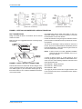
VERTICAL AND HORIZONTAL INSTALLATION KEU060, 090 AND 120
These units are built in a single cabinet with two condensate
drain pans. This allows the units to be installed in either the
vertical or horizontal position for maximum flexibility.
On vertical applications, the air velocity the cooling coil keeps
the condensate from dripping off the finned surface onto the
filters.
On horizontal applications, the unit must be installed with the
condensate drain pan under the entire cooling coil.
•
The Supply Air Plenum and the Return Air Grill accessories can be used on either arrangement.
•
The Base accessory can only be used on the vertical
arrangement.
Units installed horizontally are designed for ceiling suspension. Four 3/8”-16 weld nuts are provided in the angle supports on the front of the unit (the side with the logo).
Knockouts are provided in the exterior panels for access to
these weld nuts. The hanger rods must be supplied in the
field.
$,5
287
%/2:(5
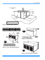
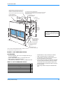
VERTICAL AND HORIZONTAL INSTALLATION KEU180
This unit has two distinct modules a blower module and a coil
module. Although the unit is always shipped in the vertical
position with a vertical air discharge as shown in illustration
(a), the blower module can be repositioned in the field as
shown in illustrations (b) and (c) for maximum flexibility.
•
The Supply Air Plenum, Return Air Grill and Base accessories can be applied on arrangement (a).
•
The Return Air Grill and Base accessories can be
applied on arrangement (b).
•
The Supply Air Plenum, Return Air Grill and Suspension
accessories can be applied on arrangement (c).
The blower can be repositioned per the following instructions:
1.
Remove the panels from the blower section.
2.
Remove the four Phillips machine bolts that hold the coil
and blower sections together. A bolt is located near
each corner.
3.
Move the blower section to the proper location.
4.
Attach the blower section to the coil section with the
machine bolts removed in Step 2.
5.
Before replacing the panel, see Duct Connection and
Drain Connection.
6.
Replace the panels.
%/2:(502725
5(7851$,5
'8&7)/$1*(
&2,/
&21'(16$7(
'5$,1
&211(&7,21
$,5
,1
&21'(16$7(
'5$,13$1
),/7(56
9(57,&$/326,7,21
),/7(56
5(7851
$,5'8&7
)/$1*(
&2,/
%/2:(5
$,5
,1
$,5
287
&21'(16$7(
'5$,1&211(&7,21
%/2:(502725
&21'(16$7('5$,13$1
+25,=217$/326,7,21
FIGURE 3 - VERTICAL AND HORIZONTAL
APPLICATION KEU060, 090 AND 120
8
Unitary Products Group
157224-YIM-A-0905
9(57,&$/326,7,21
+25,=217$/326,7,21
FIGURE 4 - VERTICAL AND HORIZONTAL APPLICATION KEU180
DUCT CONNECTIONS
Design and install all ducts in accordance with all national
and/or local codes.
Refer to Figure 5 for suggested method of connecting supply
air ductwork.
NON-FLA M
MA B LE
COLLA R DUC T
FLA N G E D DUC T
CONN E C TION
(FIELD FAB R ICATED )
Use flexible fiber glass or plastic cloth collars or other nonflammable material at the unit duct connections to minimize
the transmission of noise and vibration.
Insulate all ductwork running through unconditioned areas to
prevent moisture condensation and to provide more economical operation.
The return air duct flange is factory-mounted on the front of
the unit, but it can be reversed with the solid bottom panel for
horizontal applications. When the return air grill is used, the
duct connection frame is not used.
NOTE:
AIR
OUT
SUP P LY AIR
DUC TFLA N G E
BLO WE R GAS K E T
(BY INSTA LLER )
FIGURE 5 - SUPPLY AIR DUCT CONNECTIONS
Ducts should be sized no smaller than the duct flanges on the
unit or the electric heater (if used). Refer to the unit dimension details (Figure 15) and the heater detail (Figure 6) for
these sizes. Refer to Form 131002 for installation instructions
on the electric heater.
Unitary Products Group
If return air duct is not used, applicable installation
codes may limit the unit to installation only in a single story residence.
A supply air plenum (Figure 7), a base (Figure 8), and a
return air grill (Figure 9) are available as field-installed accessories, and one of the following respective instruction forms
will be packed with each.
035-16650-001 - Supply Air Plenum
035-16621-001 - Return Air Grill
035-16632-001 - Base
The supply air plenum and the return air grill should be used
in lieu of ductwork only when a free blow/free return application is practical.
9
157224-YIM-A-0905
6833/<
$,5
9(57,&$/$55$1*(0(17
6+2:1
'8&7)/$1*(
%
$
%/2:(5
81,7
+($7(5(/(0(17
&+$0%(5
&21752/%2;
$&&(663$1(/
1RW&6$DSSURYHGZLWKLQVWDOODWLRQRID
6XSSO\$LU3OHQXPDFFHVVRU\RUZLWK
D.(8XQLWLQVWDOOHGKRUL]RQWDOO\
FIGURE 6 - ELECTRIC HEAT ACCESSORY
DIMENSIONS
5 TON
7.5, 10 & 15 TON
A
16-7/8
19-1/4
B
20-1/8
22-1/4
BLOWER
UNIT
FOR VERTICAL
ARRANGEMENT
ONLY
ALTERNATE
AIR DISCHARGE
TOP
PANEL
GRILLE
WHEN OUTDOOR AIR IS REQUIRED, A HOLE CAN BE
CUT IN BACK PANEL FOR CONNECTING DUCTWORK.
BLOWER UNIT
BASE PANEL
FIGURE 8 - BASE ACCESSORY
VERTICAL
ARRANGEMENT
SHOWN
SUPPLY
AIR
BLOWER
UNIT
Plenum should be field mounted on the supply air end of blower
units for either vertical or horizontal application. For rear discharge,
rotate plenum 180 degrees. For horizontal discharge on a horizontal
unit, the grille panel and the top panel will be arranged differently.
Refer to Form 035-16650-001 for installation and assembly instructions.
FIGURE 7 - SUPPLY AIR PLENUM ACCESSORY
VERTICAL
ARRANGEMENT
SHOWN
FIGURE 9 - RETURN AIR GRILL ACCESSORY
10
Unitary Products Group
157224-YIM-A-0905
DRAIN CONNECTION
penetrate a wall to reduce vibration and to retain some flexibility.
The drain line must be trapped because the coil is located on
the negative side of the supply air blower. It must be protected from freezing temperatures.
A 7/8" O.D. drain connection extends through right hand side
of cabinet. Refer to Figure 10 for recommended drain piping.
Support all refrigerant lines at minimum intervals with suitable
hangers, brackets or clamps. Braze all copper-to-copper
joints with Sil-Fos 5 or equivalent brazing material. Do not
use soft solder.
Never braze or solder the liquid and suction lines together.
The drain connection is located on the same side of the unit
as the refrigerant connections. The line should be insulated
where moisture dripping will be objectionable or cause damage to the area.
The complete suction line should be insulated with no less
than 1/2" ARMAFLEX or equivalent. If the liquid and suction
lines are to be taped together for support purposes, they
must be completely insulated from one another.
The 3" dimension must equal or exceed the negative static
pressure developed by the supply air blower. If it does not,
the condensate will not drain properly and may overflow the
drain pan. The trap must be at least 2-1/2" deep to maintain
a water seal under all operating conditions, especially during
blower start-up.
INSTALLING REFRIGERANT MAINS
FIGURE 10 - RECOMMENDED DRAIN PIPING
NOTE: The unit may have to be raised off the floor to allow
enough height for the drain trap.
The blower units are shipped with the coil section side panels
suitable for right hand piping connections when viewed from
the return air side of the unit.
In left hand piping is required, the two panels on the right side
of the coil section can be interchanged with the single panel
on the left side of the coil section.
When left-hand piping connections are installed, the suction
line must be insulated to prevent moisture from condensing
and being carried into the blower section.
The units are evacuated, dehydrated and shipped with a
holding charge of Refrigerant-22 from the factory. They can
be checked for a refrigerant leak by attaching a pressure
gauge to the service ports that are located on each suction
line. DO NOT release the holding charge.
NOTE:
Some units are shipped with a nitrogen holding
charge. Check for Red Caution tag attached to the
refrigerant tubing connections.
If the pressure gauge indicates zero, the unit should be leak
tested and the necessary repairs made.
If the unit has maintained its holding charge, you can assume
that it has no leaks and proceed with the installation.
REFRIGERANT MAINS
Many service problems can be avoided by taking adequate
precautions to provide an internally clean and dry system and
by using procedures and materials that conform with established standards.
Hard drawn copper tubing should be used where no appreciable amount of bending around pipes or other obstructions
is necessary. Use long radius ells wherever possible with
one exception. Use short radius ells for traps in all vertical
suction risers. If soft copper must be used, avoid sharp
bends, which may cause a restriction.
Fiberglass insulation and a sealing material such as permagum should be packed around refrigerant lines where they
Unitary Products Group
NOTE:
Refrigerant holding charge must be reclaimed.
NOTE:
To minimize the possibility of system failure due to
dirt and moisture, a filter-drier must be installed in
the liquid line as close to the evaporator as possible.
Filter-driers are not supplied with the evaporator
blowers. They are supplied with the matching condensing sections.
If solenoid valves are required, they must be purchased and
installed in the field. The temperature required to make or
break a brazed joint is sufficiently high to cause oxidation of
the copper unless an inert atmosphere is provided.
11
157224-YIM-A-0905
When left-hand piping connections are installed, the suction
line must be insulated to prevent moisture from condensing
and being carried into the blower section.
Dry nitrogen should flow through the system at all
times when heat is being applied and until the joint
has cooled.
NOTE:
The liquid and suction connections must be piped outside the
unit. Refer to the unit drawing for locations and the dimensions of these connections.
Before brazing the refrigerant lines to these connections,
remove the short panel from the unit frame and slide it (along
with the grommets) onto the refrigerant lines. After the
brazed joints have cooled, slide the panel back into place and
secure it to the unit frame.
The blower units are shipped with the coil section side panels
suitable for right hand piping connections when viewed from
the return air side of the unit.
In left hand piping is required, the two panels on the right side
of the coil section can be interchanged with the single panel
on the left side of the coil section.
These units can only be piped from one side of the
unit.
EXPANSION VALVE BULB
On KEU060 and 090 units, the expansion valve bulb must be
fastened in a 4 o'clock position to the suction line outside the
cabinet after the piping connections have been made.
On KEU120 units, fasten the expansion valve bulb on the
suction header 8" below the top of the header, and adjacent
to the coil.
On KEU180 units, the expansion valve bulb must be fastened
in a 10 or 2 o'clock position to the suction line outside the
cabinet after the piping connections have been made.
Use the clamps provided with the valve to secure the bulb in
position. Bulb must be insulated with armaflex or mastic to
assure proper operation.
1-PHASE LINE VOLTAGE
TERMINALS ON SUPPLY AIR
POWER SUPPLY
BLOWER MOTOR CONTACTOR 10M
POWER WIRING DISCONNECT
SWITCH AND FUSING TO BE
SUPPLIED BY FIELD
R
R
Y
B
O
G
Y
O
1- PHASE
KEU060
O
24-VOLT
W
24-VOLT
TERMINALS ON
CONTROL
X
CONTROL
TERMINALS ON
1ST STAGE
WIRING
53
WIRING
COMPRESSOR
COOLING
G
CONTACTOR 1 M
THERMOSTAT
60
OF CONDENSING UNIT
66
NOTE: USE COPPER
CONDUCTORS ONLY
3-PHASE LINE VOLTAGE
TERMINALS ON SUPPLY AIR
POWER SUPPLY
BLOWER MOTOR CONTACTOR 10M
POWER WIRING DISCONNECT
SWITCH AND FUSING TO BE
SUPPLIED BY FIELD
R
R
Y
B
T
G
Y
C
V
3- PHASE
KEU090,120, 180
O
24-VOLT
W
24-VOLT
TERMINALS ON
CONTROL
X
CONTROL
TERMINALS ON
1ST STAGE
WIRING
53
WIRING
COMPRESSOR
COOLING
G
CONTACTOR 3TB
THERMOSTAT
60
OF CONDENSING UNIT
66
The field wiring connected to dummy
terminals R and Y on 4TB can be
routed directly from the condensing
unit to the thermostat if desired.
WIRE IN ACCORDANCE WITH LOCAL
AND NATIONAL ELECTRICAL CODES
FIGURE 11 - TYPICAL FIELD WIRING
12
Unitary Products Group
157224-YIM-A-0905
POWER AND CONTROL WIRING
Install electrical wiring in accordance with the latest National
Electrical Code (NFPA Standard No. 70 and/or local regulations). The unit must be grounded in accordance with these
codes.
POWER WIRING
Remove the knockout from the units rear panel (7/8" for
KEU060 and KEU180, 1-3/8" for KEU090, and 120) for power
wiring conduit through this opening. Connect the conduit to
the required field-supplied fitting and the power wiring to
blower motor contactor 10M in unit control box.
If the unit includes an electric heat accessory, route the
power wires into heater control box in lieu of the unit. Refer
to electric heat instruction 131002 for additional installation
information.
CONTROL WIRING
Route the low voltage control wiring through the 7/8" hole
(with bushing) in the units rear panel. Add a 1/2" conduit fitting to the 7/8" hole in the unit control box, route control wiring
through this opening and connect them to the terminals on
block 4TB.
Blower unit Model KEU060 contains a low voltage control
transformer (1T), which supplies the 24-volt control voltage
for its operation and for the operation of the condensing unit.
To prevent possible interconnection between 24-volt
circuits, the condensing unit being used with Model
KEU060 blower unit must NOT contain its own 24volt power supply.
CONTROL WIRE SIZING
Wire Size
Maximum Total Circuit
Length (Feet)
#19 Solid
#18 Solid
#18 Stranded
#16 Stranded
#14 Stranded
#12 Stranded
130
170
180
270
455
730
To determine the total circuit length, add the following distances:
1 - Outdoor Unit to Indoor Unit
2 - Indoor Unit to Thermostat
3 - Thermostat to Indoor Unit
4 - Indoor Unit to Outdoor Unit
5 - Outdoor Unit to Elec. Heater
Total Circuit Length
_____________
_____________
_____________
_____________
_____________
_____________
Refer to Figures 15, 16 & 17 for location of power and control
wiring openings in rear panel of the units. Refer to Figure 11
for typical field wiring. Refer to Table 7 to size the disconnect
switch, the power wiring and the fuses.
NOTE: Three phase motor rotations may be incorrect when
unit is first started. Reverse phase (leads L1 and L2)
at blower motor contactor to obtain correct rotation.
Unitary Products Group
13
157224-YIM-A-0905
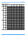
TABLE 7: KEU ELECTRICAL DATA
Model
(TONS)
Power
Supply
Voltage
Indoor
Motor
FLA
208
7.6
240
6.9
208
6.6
240
6.0
460
3.0
575
2.4
208
7.5
240
6.8
460
3.4
575
2.7
0603
(5)
090
(7.5)
120
(10)
14
Heater
Model
Number
Nominal
Heater
KW
Applied
Heater KW
Electric
Heat Amps
Min.
Circuit
Ampacity
(AMPS)
Max. Fuse1 /
HACR
Breaker2
(AMPS)
None
2HT04501025
2HT04501625
2HT04502625
None
2HT04501025
2HT04501625
2HT04502625
None
2HS04501025
2HS04501625
2HS04502625
2HS04503625
None
2HS04501025
2HS04501625
2HS04502625
2HS04503625
None
2HS04501046
2HS04501646
2HS04502646
2HS04503646
None
2HS04501058
2HS04501658
2HS04502658
2HS04503658
None
2HS04501025
2HS04501625
2HS04502625
2HS04503625
None
2HS04501025
2HS04501625
2HS04502625
2HS04503625
None
2HS04501046
2HS04501646
2HS04502646
2HS04503646
None
2HS04501058
2HS04501658
2HS04502658
2HS04503658
-10
16
26
-10
16
26
-10
16
26
36
-10
16
26
36
-10
16
26
36
-10
16
26
36
-10
16
26
36
-10
16
26
36
-10
16
26
36
-10
16
26
36
-7.5
12.0
19.5
-10.0
16.0
26.0
-7.5
12.0
19.5
27.0
-10.0
16.0
26.0
36.0
-10.0
16.0
26.0
36.0
-10.0
16.0
26.0
36.0
-7.5
12.0
19.5
27.0
-10.0
16.0
26.0
36.0
-10.0
16.0
26.0
36.0
-10.0
16.0
26.0
36.0
-20.8
33.4
54.2
-24.1
38.5
62.5
-20.8
33.4
54.2
75.1
-24.1
38.5
62.5
86.6
-12.0
19.2
31.3
43.3
-9.6
15.4
25.0
34.6
-20.8
33.4
54.2
75.1
-24.1
38.5
62.5
86.6
-12.0
19.2
31.3
43.3
-9.6
15.4
25.0
34.6
9.5
35.6
51.2
77.3
8.6
38.7
56.7
86.8
8.3
34.3
49.9
76.0
102.1
7.5
37.6
55.6
85.7
115.8
3.8
18.8
27.8
42.8
57.9
3.0
15.0
22.2
34.3
46.3
9.4
35.4
51.1
77.1
103.2
8.5
38.6
56.6
86.7
116.8
4.3
19.3
28.3
43.3
58.4
3.4
15.4
22.6
34.6
46.7
15
40
60
80
15
40
60
90
15
35
50
80
110
15
40
60
90
125
15
20
30
45
60
15
20
25
35
50
15
40
60
80
110
15
40
60
90
125
15
20
30
45
60
15
20
25
35
50
Unitary Products Group
157224-YIM-A-0905
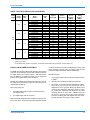
TABLE 7: KEU ELECTRICAL DATA (CONTINUED)
Model
(TONS)
Power
Supply
Voltage
Indoor
Motor
FLA
208
10.6
240
9.6
460
4.8
575
3.9
180
(15)
Heater
Model
Number
Nominal
Heater
KW
Applied
Heater KW
Electric
Heat Amps
Min.
Circuit
Ampacity
(AMPS)
Max. Fuse1 /
HACR
Breaker2
(AMPS)
None
2HS04501025
2HS04501625
2HS04502625
2HS04503625
2HS04507225
None
2HS04501025
2HS04501625
2HS04502625
2HS04503625
2HS04507225
None
2HS04501046
2HS04501646
2HS04502646
2HS04503646
2HS04507246
None
2HS04501058
2HS04501658
2HS04502658
2HS04503658
2HS04507258
-10
16
26
36
72
-10
16
26
36
72
-10
16
26
36
72
-10
16
26
36
72
-7.5
12.0
19.5
27.0
54.1
-10.0
16.0
26.0
36.0
72.0
-10.0
16.0
26.0
36.0
72.0
-10.0
16.0
26.0
36.0
72.0
-20.8
33.4
54.2
75.1
150.1
-24.1
38.5
62.5
86.6
173.2
-12.0
19.2
31.3
43.3
86.6
-9.6
15.4
25.0
34.6
69.3
13.3
39.3
54.9
81.0
107.1
200.9
12.0
42.1
60.1
90.2
120.3
228.5
6.0
21.0
30.1
45.1
60.1
114.3
4.9
16.9
24.1
36.1
48.2
91.5
20
40
60
90
110
225
15
45
70
100
125
250
15
25
35
50
70
125
15
20
25
40
50
100
1.
Dual element time delay.
2.
HACR type per NEC.
3.
The K*EU060 indoor motor is single phase. The electrical heaters MUST be supplied with 3-phase voltage only.
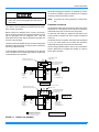
SUPPLY AIR BLOWER ADJUSTMENT
The RPM of the supply air blower will depend on the required
CFM, the unit accessories and the static resistances of both
the supply and the return air duct system. With this information, the RPM for the supply air blower can be determined
from the blower performance shown in Table 9.
Knowing the required blower RPM and the blower motor HP,
the setting (turns open) for the supply air motor pulley can be
determined from Table 8.
Each motor pulley has:
1.
A threaded barrel with two flats (or notched recesses)
180 degrees apart.
2.
A movable flange with one set screw.
After the movable flange has been rotated to the proper number of “turns open”; the set screw should be tightened against
Unitary Products Group
the flat on the barrel to lock the movable flange in place. If the
pulley includes a locking collar, the locking collar must be
loosened to adjust the setting of the movable flange.
Note the following:
1.
The supply air CFM must be within the limitations shown
in Table 3.
2.
All Pulleys can be adjusted in half turn increments.
3.
The tension on the belt should be adjusted for a deflection of 3/16 of an inch per foot of belt span with an
applied force of 2 to 3 pounds. Moving the blower motor
mounting plate makes this adjustment. Refer to Figure
12. Turning the adjustment bolt (B) moves the motor
mounting plate up or down. Note - NEVER loosen the
two nuts (C). Two hex nuts (A) have to be loosened to
move the mounting plate and retighten after the mounting plate has been moved to the proper position.
15
157224-YIM-A-0905
TABLE 8: SUPPLY AIR BLOWER MOTOR PULLEY
ADJUSTMENT
%
Blower (RPM)
Turns
Open
060
090
120
180
5
4
3
2
1
0
810
870
930
990
1050
1110
655
700
745
790
835
880
700
750
800
850
900
950
625
660
700
735
775
810
C
(DO NOT LOOSEN)
+2/(
$
(9$325$725
&2,/
&
$,5
,1
B
MOTOR MOUNT
+2/(
'
),/7(56
MOTOR
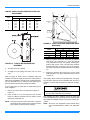
FIGURE 13 - HOLE LOCATIONS (PRESSURE DROP
READINGS)
A
Model
060
090
120
180
All pulleys are factory aligned.
5.
All supply air motor pulleys are factory set at 3 “turns
open”.
After the supply air blower motor is operating, adjust the
resistances in both the supply and the return duct systems to
balance the air distribution throughout the conditioned space.
The job specifications may require that this balancing be
done by someone other than the equipment installer.
Dimensions (in.)
B
C
14-3/4
19
17
14
17
14
22
18
D
6-3/4
8
8
10
3.
Using an inclined manometer, determine the pressure
drop across a dry evaporator coil. Since the moisture
on an evaporator coil may vary greatly, measuring the
pressure drop across a wet coil under field conditions
would be inaccurate. To assure a dry coil, the refrigeration system should be de-activated while the test is being
run.
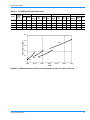
4.
Knowing the pressure drop across a dry coil, the actual
CFM through the unit can be determined from the curve
in Figure 14.
FIGURE 12 - TYPICAL MOTOR MOUNTING
ASSEMBLY
4.
A
9-1/2
3
3
7
If the CFM is above or below the specified value, the supply
air motor pulley may have to be re-adjusted. After one hour of
operation, check the belt and pulleys for tightness and alignment.
To check the supply air CFM after the initial balancing has
been completed:
1.
Drill two 5/16-inch holes in the side panel as shown in
Figure 12.
2.
Insert at least 8" of 1/4 inch tubing into each of these
holes for sufficient penetration into the airflow on both
sides of the evaporator coil.
NOTE: The tubes must be inserted and held in a position
perpendicular to the airflow so that velocity pressure
will not affect the static pressure readings.
16
Failure to properly adjust the total system air quantity can result in extensive blower damage.
After readings have been obtained, remove the tubes and
seal up the drilled holes in the side panel 5/16" dot plugs (P/N
029-13880) are available through normal parts ordering procedures.
NOTE: Shut down the refrigeration system before taking
any test measurements to assure a dry evaporator
coil.
Unitary Products Group
157224-YIM-A-0905
TABLE 9: BLOWER MOTOR AND DRIVE DATA
MOTOR
MODEL
BLOWER
RANGE
(RPM)
ADJUSTABLE MOTOR PULLEY
HP
FRAME
DESIGNATION
OUTSIDE
DIA.
(IN.)
PITCH
DIA.
(IN.)
BORE
(IN.)
FIXED BLOWER PULLEY
BELT (NOTCHED)
DESIGNATION
OUTSIDE
DIA.
(IN.)
PITCH
DIA.
(IN.)
BORE
(IN.)
DESIGNATION
PITCH
LENGTH
(IN.)
QTY.
060
810/1110
3/4
56
1VL44
3.1-4.1
2.8-3.8
5/8
AL64
6.2
5.8
3/4
A32
33.3
1
090
655/880
1-1/2
56
1VL44
2.1-4.1
2.8-3.8
7/8
AK79
7.9
7.5
1
A36
37.3
1
120
700/950
2
56
1VL44
3.1-4.1
2.8-3.8
7/8
BK80
7.4
7.0
1
A36
37.3
1
180
625/810
3
56
1VM50
3.7-4.7
3.4-4.4
7/8
BK105
9.9
9.5
1
A57
58.3
1
0.5
Pressure Drop (IWG)
0.4
180
0.3
0.2
0.1
090
120
060
0
1500
2500
3500
4500
5500
6500
7500
CFM
FIGURE 14 - PRESSURE DROP ACROSS A DRY EVAPORATOR COIL VS. SUPPLY AIR CFM
Unitary Products Group
17
157224-YIM-A-0905
TABLE 10: KEU060 (5 TON) BELT DRIVE BLOWER PERFORMANCE
5 TON BLOWER PERFORMANCE1,2
ESP3
0.2
0.3
0.4
0.5
0.6
0.7
0.8
0.9
1
1.1
1.2
0 Turns Open
CFM
------------------------1895
1710
1516
TURNS OPEN4
2 Turns Open
3 Turns Open
1 Turn Open
5
RPM W BHP CFM
------- ---- ---------- ---- ---------- ---- ---------- ---- ---------- ---- ---------- ---- ---------- ---- 1979
------- ---- 1809
1112 801 0.86 1631
1114 700 0.75 1446
1117 591 0.63 ----
RPM
------------------1054
1056
1058
1060
----
W5
------------------779
693
599
498
----
BHP
------------------0.84
0.74
0.64
0.53
----
CFM
---------2203
2051
1893
1729
1558
1381
-------
RPM
---------991
993
995
998
1000
1002
-------
W5
---------809
743
670
590
504
411
-------
BHP
---------0.87
0.80
0.72
0.63
0.54
0.44
-------
CFM
2393
2255
2112
1965
1813
1655
1491
-------------
RPM
927
929
931
933
935
937
939
-------------
W5
800
750
694
633
567
494
414
-------------
4 Turns Open
BHP
0.86
0.80
0.74
0.68
0.61
0.53
0.44
-------------
CFM
2169
2030
1888
1741
1589
1431
----------------
RPM
867
869
871
873
875
877
----------------
W5
637
587
531
470
404
331
----------------
5 Turns Open
BHP
0.68
0.63
0.57
0.50
0.43
0.35
----------------
CFM
1957
1819
1677
1529
----------------------
RPM
804
806
808
810
----------------------
W5
487
437
381
320
----------------------
BHP
0.52
0.47
0.41
0.34
----------------------
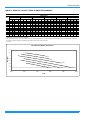
1. Blower performance does not include accessories.
2. Blower performance includes one-inch throwaway filters.
3. ESP (External Static Pressure) given is that available for the supply and return air duct system. All internal resistances have been deducted from the total static pressure of the blower.
4. “Turns Open” refers to the setting of the variable pitch motor sheave, where “0 Turns Open” is fully closed.
5. W = Watts
5 Ton Belt Drive Blower Performance
1.4
1.2
ESP (IWG)
1
0 Turns
0.8
1 Turn
0.6
2 Turns
0.4
0.2
0
1250
5 Turns
1500
1750
2000
4 Turns
2250
3 Turns
2500
CFM
18
Unitary Products Group
157224-YIM-A-0905
TABLE 11: KEU090 (7.5 TON) BELT DRIVE BLOWER PERFORMANCE
7.5 TON BLOWER PERFORMANCE1,2
ESP3
0.2
0.3
0.4
0.5
0.6
0.7
0.8
0.9
1
1.1
1.2
0 Turns Open
5
CFM RPM W BHP
---- ------- ------- ------- ------- ------- ------- ------- ------- ------- ---3892 891 1624 1.74
3610 892 1525 1.64
3318 891 1416 1.52
3017 890 1296 1.39
2708 886 1164 1.25
2392 881 1020 1.09
1 Turn Open
5
CFM RPM W
---- ---------- ------4250 836 1619
4011 839 1546
3756 841 1465
3487 843 1376
3206 844 1277
2914 843 1168
2613 842 1048
2304 838 916
---- -------
BHP
------1.74
1.66
1.57
1.48
1.37
1.25
1.12
0.98
----
TURNS OPEN4
2 Turns Open
3 Turns Open
5
5
CFM RPM W BHP CFM RPM W BHP
4274 785 1504 1.61 3875 738 1273 1.37
4071 787 1445 1.55 3672 740 1213 1.30
3849 789 1379 1.48 3450 743 1147 1.23
3609 792 1306 1.40 3211 745 1074 1.15
3355 794 1225 1.31 2956 748 994 1.07
3086 796 1136 1.22 2687 749 904 0.97
2805 796 1037 1.11 2406 750 805 0.86
2513 796 928 1.00 ---- ------- ---2212 794 808 0.87 ---- ------- ------- ---- ---- ---- ---- ------- ------- ---- ---- ---- ---- ------- ----
4 Turns Open
5
CFM RPM W BHP
3480 693 1049 1.13
3276 695 990 1.06
3054 698 924 0.99
2815 700 851 0.91
2560 702 770 0.83
2292 704 681 0.73
---- ------- ------- ------- ------- ------- ------- ------- ------- ------- ----
5 Turns Open
5
CFM RPM W BHP
3087 649 834 0.90
2883 651 775 0.83
2661 653 709 0.76
2422 656 636 0.68
2167 658 555 0.60
---- ------- ------- ------- ------- ------- ------- ------- ------- ------- ------- ------- ----
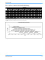
1. Blower performance does not include accessories.
2. Blower performance includes one-inch throwaway filters.
3. ESP (External Static Pressure) given is that available for the supply and return air duct system. All internal resistances have been deducted from the total static pressure of the blower.
4. “Turns Open” refers to the setting of the variable pitch motor sheave, where “0 Turns Open” is fully closed.
5. W = Watts
7.5 Ton Belt Drive Blower Performance
1.4
1.2
ESP (IWG)
1
0.8
0 Turns
0.6
0.4
1 Turn
0.2
0
2000
5 Turns
2250
2500
2750
3000
3250
4 Turns
3500
3 Turns
3750
4000
2 Turns
4250
4500
CFM
Unitary Products Group
19
157224-YIM-A-0905
TABLE 12: KEU120 (10 TON) BELT DRIVE BLOWER PERFORMANCE
10 TON BLOWER PERFORMANCE1,2
ESP3
0.2
0.3
0.4
0.5
0.6
0.7
0.8
0.9
1
1.1
1.2
1.3
1.4
0 Turns Open
5
CFM RPM W BHP
---- ------- ------- ------- ------- ------- ------- ------- ------- ------- ------- ------- ------- ------- ------- ------- ---4179 948 2105 2.26
3949 950 1963 2.11
3698 952 1808 1.94
3421 954 1637 1.76
3113 957 1449 1.55
1 Turn Open
5
CFM RPM W
---- ---------- ---------- ---------- ------4555 896 2134
4364 897 2035
4169 899 1928
3968 900 1810
3754 902 1682
3524 904 1540
3273 906 1385
2996 908 1214
---- -------
BHP
------------2.29
2.18
2.07
1.94
1.80
1.65
1.49
1.30
----
TURNS OPEN4
2 Turns Open
3 Turns Open
5
5
CFM RPM W BHP CFM RPM W BHP
4978 843 2092 2.24 4590 795 1752 1.88
4752 844 2013 2.16 4364 797 1673 1.79
4542 846 1931 2.07 4154 798 1591 1.71
4342 847 1845 1.98 3954 800 1504 1.61
4149 849 1753 1.88 3761 801 1413 1.52
3957 850 1654 1.77 3570 803 1314 1.41
3763 852 1546 1.66 3375 804 1206 1.29
3561 853 1429 1.53 3174 806 1089 1.17
3348 855 1300 1.39 2960 807 960 1.03
3117 857 1159 1.24 ---- ------- ---2866 859 1003 1.08 ---- ------- ------- ---- ---- ---- ---- ------- ------- ---- ---- ---- ---- ------- ----
4 Turns Open
5
CFM RPM W BHP
4221 747 1453 1.56
3995 748 1374 1.47
3785 750 1292 1.39
3585 751 1206 1.29
3392 753 1114 1.20
3200 754 1015 1.09
3006 756 908 0.97
---- ------- ------- ------- ------- ------- ------- ------- ------- ------- ------- ------- ----
5 Turns Open
5
CFM RPM W BHP
3870 698 1196 1.28
3645 700 1117 1.20
3434 701 1035 1.11
3234 703 949 1.02
3041 704 857 0.92
---- ------- ------- ------- ------- ------- ------- ------- ------- ------- ------- ------- ------- ------- ------- ------- ----
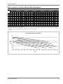
1. Blower performance does not include accessories.
2. Blower performance includes one-inch throwaway filters.
3. ESP (External Static Pressure) given is that available for the supply and return air duct system. All internal resistances have been deducted from the total static pressure of the blower.
4. “Turns Open” refers to the setting of the variable pitch motor sheave, where “0 Turns Open” is fully closed.
5. W = Watts
10 Ton Belt Drive Blower Performance
1.6
1.4
ESP (IWG)
1.2
1
0 Turns
0.8
0.6
1 Turn
0.4
0.2
0
2750
5 Turns
3000
3250
3500
3750
4000
4 Turns
4250
3 Turns
4500
4750
2 Turns
5000
5250
CFM
20
Unitary Products Group
157224-YIM-A-0905
TABLE 13: KEU180 (15 TON) BELT DRIVE BLOWER PERFORMANCE
15 TON BLOWER PERFORMANCE1,2
ESP3
0.2
0.3
0.4
0.5
0.6
0.7
0.8
0.9
1
1.1
1.2
1.3
1.4
0 Turns Open
5
CFM RPM W BHP
---- ------- ------- ------- ------- ------- ------- ------- ------- ------- ------- ------- ------- ------- ---6291 797 3185 3.42
5833 800 2943 3.16
5337 802 2674 2.87
4798 806 2378 2.55
4210 810 2050 2.20
3568 814 1688 1.81
1 Turn Open
5
CFM RPM W
---- ---------- ---------- ---------- ------6756 762 3225
6381 764 3041
5984 766 2841
5559 768 2620
5101 770 2377
4606 773 2109
4067 776 1813
3479 780 1485
---- -------
BHP
------------3.46
3.26
3.05
2.81
2.55
2.26
1.94
1.59
----
TURNS OPEN4
2 Turns Open
3 Turns Open
5
5
CFM RPM W BHP CFM RPM W BHP
---- ---- ---- ---- 6762 687 2752 2.95
7097 724 3151 3.38 6424 690 2605 2.80
6757 726 3000 3.22 6084 692 2454 2.63
6411 728 2840 3.05 5738 694 2294 2.46
6053 730 2670 2.86 5380 696 2124 2.28
5679 732 2486 2.67 5005 698 1940 2.08
5281 734 2285 2.45 4608 699 1739 1.87
4857 736 2065 2.22 4184 702 1519 1.63
4399 739 1822 1.95 3726 704 1276 1.37
3903 741 1554 1.67 ---- ------- ------- ---- ---- ---- ---- ------- ------- ---- ---- ---- ---- ------- ------- ---- ---- ---- ---- ------- ----
4 Turns Open
5
CFM RPM W BHP
6118 650 2216 2.38
5780 653 2069 2.22
5440 655 1917 2.06
5094 657 1758 1.89
4736 659 1587 1.70
4361 660 1403 1.51
3964 662 1203 1.29
3540 665 982 1.05
---- ------- ------- ------- ------- ------- ------- ------- ------- ------- ----
5 Turns Open
5
CFM RPM W BHP
5504 610 1689 1.81
5165 613 1542 1.65
4825 615 1390 1.49
4479 617 1231 1.32
4121 619 1061 1.14
3747 621 876 0.94
---- ------- ------- ------- ------- ------- ------- ------- ------- ------- ------- ------- ------- ------- ----
1. Blower performance does not include accessories.
2. Blower performance includes one-inch throwaway filters.
3. ESP (External Static Pressure) given is that available for the supply and return air duct system. All internal resistances have been deducted from the total static pressure of the blower.
4. “Turns Open” refers to the setting of the variable pitch motor sheave, where “0 Turns Open” is fully closed.
5. W = Watts
15 Ton Belt Drive Blower Performance
1.6
1.4
ESP (IWG)
1.2
1
0 Turns
0.8
0.6
1 Turn
0.4
2 Turns
0.2
0
3500
5 Turns
3750
4000
4250
4500
4750
5000
5250
5500
5750
4 Turns
6000
6250
3 Turns
6500
6750
7000
7250
CFM
Unitary Products Group
21
157224-YIM-A-0905
TABLE 14: KEU060-120 STATIC RESISTANCE FOR UNIT ACCESSORIES (IWG)
CFM
2200
2400
2600
2800
3000
3200
3400
3600
3800
4000
4200
4400
4600
4800
5000
Electric Heat KW
10
16
26
36
Supply Air
Plenum
Return
Air Grill
Hot Water
Coil
Steam
Coil
0.01
0.01
0.01
0.01
0.01
0.02
0.02
0.02
0.02
0.03
0.03
0.03
0.03
0.04
0.04
0.01
0.02
0.02
0.03
0.03
0.04
0.04
0.05
0.06
0.06
0.07
0.07
0.08
0.08
0.09
0.03
0.03
0.04
0.04
0.05
0.06
0.07
0.07
0.08
0.09
0.10
0.11
0.12
0.13
0.14
0.04
0.05
0.06
0.07
0.08
0.09
0.10
0.11
0.12
0.14
0.15
0.16
0.18
0.19
0.21
0.02
0.03
0.03
0.04
0.04
0.05
0.05
0.06
0.06
0.07
0.07
0.08
0.09
0.10
0.10
0.02
0.03
0.03
0.04
0.04
0.05
0.05
0.06
0.06
0.07
0.07
0.08
0.09
0.10
0.10
0.07
0.09
0.10
0.12
0.14
0.16
0.17
0.19
0.22
0.24
0.26
0.28
0.31
0.33
0.36
0.11
0.13
0.15
0.16
0.18
0.20
0.23
0.25
0.27
0.30
0.33
0.36
0.39
0.43
0.46
TABLE 15: KEU180 STATIC RESISTANCE FOR UNIT ACCESSORIES (IWG)
CFM
4600
4800
5000
5200
5400
5600
5800
6000
6200
6400
6600
6800
7000
7200
7400
22
Electric Heat KW
10
16
26
36
72
Supply Air
Plenum
Return
Air Grill
Hot Water
Coil
Steam
Coil
0.03
0.04
0.04
0.04
0.05
0.05
0.06
0.06
0.07
0.07
0.08
0.08
0.09
0.09
0.10
0.08
0.08
0.09
0.10
0.10
0.11
0.11
0.12
0.13
0.13
0.14
0.15
0.15
0.16
0.17
0.12
0.13
0.14
0.16
0.17
0.18
0.20
0.21
0.22
0.24
0.25
0.27
0.29
0.30
0.32
0.18
0.19
0.21
0.23
0.24
0.26
0.28
0.30
0.32
0.34
0.36
0.38
0.41
0.43
0.45
0.23
0.25
0.27
0.29
0.31
0.34
0.37
0.40
0.43
0.47
0.51
0.55
0.59
0.64
0.68
0.05
0.06
0.06
0.06
0.07
0.07
0.08
0.08
0.08
0.09
0.09
0.10
0.10
0.10
0.11
0.05
0.06
0.06
0.06
0.07
0.07
0.08
0.08
0.08
0.09
0.09
0.10
0.10
0.10
0.11
0.31
0.33
0.36
0.38
0.41
0.44
0.47
0.50
0.53
0.56
0.59
0.62
0.66
0.69
0.73
0.39
0.43
0.46
0.50
0.54
0.58
0.62
0.66
0.71
0.75
0.80
0.85
0.90
0.95
1.01
Unitary Products Group
157224-YIM-A-0905
(/,%7"53().'
).2%!20!.%,
&OR,OW6OLTAGE
#ONTROL0ANEL
+./#+/54
2EMOVEDONLYWHEN
%LECTRIC(EAT!CCESSORY
ISUSED
!)2
/54
+./#+/54
).2%!20!.%,
&OR0OWER7IRING
",/7%2-/4/2
!.$$2)6%
!##%330!.%,
4HISSIDEINLY
&),4%2!##%33
0!.%,4HIS
SIDEONLY
(/,%7)4('2/-
-%4&/2/$
35#4)/.,).%
All dimensions are in inches. They
are subject to change without notice.
Certified dimensions will be provided
upon request.
!)2
).
(/,%7)4('2/-
-%4&/2/$
,)15)$,).%
/$$2!).
#/..-USTBE
TRAPPED
FIGURE 15 - UNIT DIMENSIONS KEU060
ACCESSORIES
•
•
•
ELECTRIC HEATER - Add 13” to unit height when used.
SUPPLY AIR PLENUM - Add 24-1/4” to unit height when used.
BASE - Add 20” to unit height when used.
1.
Overall dimensions of the unit will vary if an electric
heater, a supply air plenum or a base is used.
2.
This dimension is required for removal of the coil. Only
26” is required for normal service.
3.
Although no clearance is required for service and operation, some clearance may be required for routing the
power and control wiring.
4.
Allow enough clearance to trap the condensate drain
line.
TABLE 16: UNIT CLEARANCES KEU060
MINIMUM CLEARANCES
Side with RETURN AIR opening
060
24”
Side with SUPPLY AIR opening1
24”
2
Side with PIPING CONNECTIONS
36”
Side opposite with PIPING CONNECTIONS
12”
Side with access for both POWER & CONTROL
WIRING3,
Bottom4
Unitary Products Group
-
23
157224-YIM-A-0905
+./#+/54
&/20/7%27)2).'"ACK0ANEL
$ONOTREMOVETHISKNOCKOUTWHEN
THEUNITISEQUIPPEDWITHAN%LECTRIC
(EAT!CCESSORY2EFERTODETAILOF
THE(EATER!CCESSORYFORPOWER
WIRINGACCESSOPENING
(/,%7"53().'
&/2#/.42/,
7)2).'
"ACK0ANEL
+./#+/54
2EMOVEDONLYWHEN
%LECTRIC(EAT!CCESSORY
ISUSED
!)2
/54
",/7%2-/4/2
!.$$2)6%
!##%330!.%,
4HISSIDEONLY
(/,%7)4('2/-
-%4&/2/$
,)15)$,).%
(/,%7)4('2/-
-%4&/2/$
35#4)/.,).%
!)2
).
All dimensions are in inches. They
are subject to change without notice.
Certified dimensions will be provided
upon request.
/$$2!).
#/..-USTBE
TRAPPED
&),4%2!##%330!.%,
7HENUNITISINSTALLEDIN
AHORIZONTALPOSITIONDO
NOTBLOCKTHISAREAWITH
REFRIGERANTPIPING
FIGURE 16 - UNIT DIMENSIONS KEU090 & 120
ACCESSORIES
•
•
•
ELECTRIC HEATER - Add 14-1/4” to unit height when used.
SUPPLY AIR PLENUM - Add 27-1/2” to unit height when used.
BASE - Add 20” to unit height when used.
1.
Overall dimensions of the unit will vary if an electric
heater, a supply air plenum or a base is used.
2.
This dimension is required for removal of the coil. Only
26” is required for normal service.
3.
Although no clearance is required for service and operation, some clearance may be required for routing the
power and control wiring.
4.
Allow enough clearance to trap the condensate drain
line.
TABLE 17: UNIT CLEARANCES KEU090 & 120
MINIMUM CLEARANCES
Side with RETURN AIR opening
090-120
24”
Side with SUPPLY AIR opening1
24”
2
Side with PIPING CONNECTIONS
52”
Side opposite with PIPING CONNECTIONS
12”
Side with access for both POWER & CONTROL
WIRING3,
Bottom4
24
-
Unitary Products Group
157224-YIM-A-0905
B L
(A
L o
s e
O W
lw a y
c a te
c tio n
E R
s o
d o
h a
M O
n th
n o
s b
T O
e w
p p o
e e n
R A N D D
ir in g c o n n
s ite s id e O
ro ta te d 1
R IV E A C C
e c tio n s id
N L Y w h e
8 0 fro m p
E S S
e o f u
n th e
o s itio
1 -2 3 /3 2 " K N O C K O U T
R e m o v e o n ly w h e n E le c tr ic
H e a t A c c e s s o r y is u s e d .
P A N E L
n it)
b lo w e r
n s h o w n .
7 /8
D o
H e
w ir
" K N O
n o t re
a t A c c
in g a c
6 0 -3 /4
2 1 -7 /8
1 9 -3 /8
C K O U T F
m o v e th is
e s s o ry . R
c e s s o p e n
7 /8 " K N O
C O N T R O
W E R W IR IN G
u t w h e n th e u n it is e q u ip p e d w ith a n E le c tr ic
d e ta il o f th e H e a te r A c c e s s o r y fo r p o w e r
T F O R
IN G
A L T E R N A T E
2 -5 /8 " K N O C K O U T *
A IR
O U T
5 -7 /8
2 -1 /8
5 -1 /2
7 /8
7 -1 /4
O R P O
k n o c k o
e fe r to
in g
C K O U
L W IR
1 8 -7 /8
3 2 -3 /8
6
1 6 -1 /2
B L O W E R
S E C T IO N
3 -1 /8
2 -5
K N
O U
1 -5
S U
C O
1 9
1 0
2 7 -5 /8
6 -1 /4
K O R
O D
IO N
.*
All dimensions are in inches. They
are subject to change without notice.
Certified dimensions will be provided
upon request.
3 -1 /8
6 2 -5 /8
C O IL
S E C T .
2 -3 /8
/8 "
O C
T F
/8 "
C T
N N
3 -1 /8
A IR
IN
1 -1
F O
C O
(M
2 -3 /1 6
5 6 -3 /8
1
3 1 -5 /8
2 -3 /1 6
F IL T
F ilte
th ro
th e
/4 " K N
7 /8 "
N N E C
u s t b e
R
O C
O D
T IO
tra p
K O U T
D R A IN
N *
p e d )
E R A C C E S S P A N E L
rs c a n b e re m o v e d
u g h e ith e r s id e o f
u n it.
1 -1 /4 " K N O C K O U T F O R
5 /8 " O D L IQ U ID C O N N E C T IO N *
* R e fe r to IN S T A L L IN G R E F R IG E R A N T M A IN S in in s ta lla tio n in s tr u c tio n
w h e n p ip in g th r o u g h th e o p p o s ite s id e o f th e u n it.
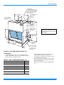
FIGURE 17 - UNIT DIMENSIONS KEU180
ACCESSORIES
•
•
•
•
ELECTRIC HEATER - Add 14-1/4” to unit height when using 10,
16, 26, or 36 KW heater
SUPPLY AIR PLENUM - Add 27” to unit height when used.
BASE - Add 24” to unit height when used.
HOT WATER OR STEAM COIL - Add 6” to unit depth when used.
1.
Overall dimension of the unit will vary if an electric
heater, a supply air plenum or a base is used.
2.
This dimension is required for removal of the DX coil.
Only 26” is required for normal servicing.
3.
If the coil has to be removed, this dimension is required
to loosen screws that secure the coil to the unit frame.
This dimension will also be required for blower motor
access if the piping connections are made on the opposite side of the unit.
4.
Allow enough clearance to trap the condensate drain
lines.
TABLE 18: UNIT CLEARANCES KEU180
MINIMUM CLEARANCES
Side Air with RETURN AIR opening
24”
24”
1
Side with SUPPLY AIR opening
61”
Side with PIPING CONNECTIONS2
Side opposite PIPING CONNECTIONS
Bottom
4
Unitary Products Group
180
3
26”
-
25
157224-YIM-A-0905
MAINTENANCE
DRAIN PAN
EVAPORATOR COIL
The drain pan should be inspected regularly to assure proper
drainage.
Do not allow dirt to accumulate on the evaporator coil or other
parts of the evaporator air circuit. Clean as often as necessary to assure good system performance. Use a brush, vacuum cleaner attachment or other suitable means.
FILTERS
The filters must be cleaned or replaced as often as necessary
to assure good airflow and filtering action.
Refer to the unit dimension detail (Figure 15) for the location
of the filter access panel.
26
LUBRICATION
The bearings for the blower shaft and the blower motor are
permanently lubricated and should not require and additional
lubrication.
BELTS
Maintain belt tension to extend belt life. Replace when signs
of failure begin to appear.
Unitary Products Group
157224-YIM-A-0905
Unitary Products Group
27
157224-YIM-A-0905
Subject to change without notice. Printed in U.S.A.
Copyright © by Unitary Products Group 2005. All rights reserved.
Supersedes: 550.23-N2Y (399) / 035-16672-000, 550.13-N76 (299) / 035-16224-000
Unitary
Products
Group
5005
York
Drive
Norman
OK
73069