1
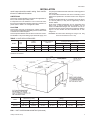
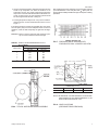
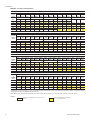
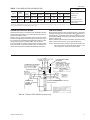
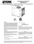
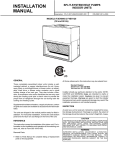
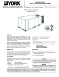
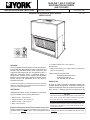
®
INSTALLATION INSTRUCTION
SUNLINE™ SPLIT-SYSTEM
EVAPORATOR BLOWERS
(AIR COOLED)
Supersedes: Nothing
550.39-N4YI (894)
035-12122
MODELS K5EU090A50A & K4EU120A50A
(WORLD 50 HZ)
GENERAL
These completely assembled blower units are manufactured under ISO 9002 Quality System Certification and
include a well-insulated cabinet, a DX cooling coil with
copper tubes and aluminum fins, an expansion valve, a
distributor, throwaway filters, a centrifugal blower, a
blower motor, a blower motor contactor, an adjustable
belt drive and a small holding charge of Refrigerant-22.
Blower motors and adjustable drives are factoryinstalled on all units.
The units are shipped in the vertical position with a vertical air
discharge. The blower section can be repositioned as shown in
Figure1 for horizontal applications.
REFERENCE
Additional information for the accessories on this equipment is available in the following instructions:
•
•
•
•
Electric Heater - 550.13-N10.1V
Supply Air Plenum - 550.13-N10.2V
Return Air Grille - 550.13-N10.3V
Base - 550.13-N10.4V
• Hot Water & Steam Coil - 550.13-N10.7V
Renewal Parts:
• Refer to Parts Manual for complete listing of replacement
parts on this equipment.
All forms may be ordered from:
Publications Distribution Center
Unitary Products Group
P.O. Box 1592, York, PA 17405
INSPECTION
As soon as a unit is received, it should be inspected for
possible damage during transit. If damage is evident, the
extent of the damage should be noted on the carrier's delivery receipt. A separate request for inspection by the
CAUTION
THIS PRODUCT M UST BE INSTALLED IN STRICT COMPLIANCE W ITH
THE ENCLOSED INSTALLATION INSTRUCTIONS AND ANY APPLICABLE
LOCAL, STATE, AND NATIONAL CODES INCLUDING, BUT NOT LIMITED
TO, BUILDING, ELECTRICAL, AND MECHANICAL CODES.
WARNING
INCORRECT INSTALLATION MAY CREATE A CONDITION WHERE THE
OPERATION OF THE PRODUCT COULD CAUSE PERSONAL INJURY
OR PROPERTY DAMAGE.
Installer should pay particular attention to the words: NOTE, CAUTION and WARNING. Notes are intended to clarify or make the installation easier. Cautions are given to prevent equipment damage. Warnings are given to alert installer that personal injury
550.39-N4YI
TABLE OF CONTENTS
TABLES
General................................................................................1
Reference ............................................................................1
No.
Inspection ............................................................................1
Description
Page
1
Unit Application Data............................................ 3
2
Physical Data ....................................................... 5
3
Supply Air Blower Motor Pulley Adjustment......... 7
Limitations ...........................................................................3
4
Blower Performance............................................. 8
Location ...............................................................................3
5
Accessory Static Resistance (IWG/pA) ................ 9
Clearances ..........................................................................4
6
Electrical Data ...................................................... 9
Rigging and Handling ..........................................................4
7
Blower Motor and Drive Data ...............................11
Nomenclature ......................................................................2
INSTALLATION
Vertical/horizontal Installation ..............................................4
FIGURES
Duct Connections ................................................................4
No.
Refrigerant Mains ................................................................5
Description
Page
1
Unit Suspension Mounting (Horizontal)................ 3
2
Vertical and Horizontal Appplication..................... 4
3
Supply Air Duct Connection ................................. 4
4
Electric Heater Accessory .................................... 4
5
Recommended Drain Piping ................................ 6
Filters.................................................................................12
6
Typical Motor Mounting Assembly ....................... 7
Evaporator Coil..................................................................12
7
Pressure Drop Across Dry Coil vs Supply Air ...... 7
Lubrication .........................................................................12
8
Hole Locations (Pressure Drop Readings)........... 7
Drain Pan ..........................................................................12
9
Unit Dimensions and Clearances.........................10
Belts...................................................................................12
10
Typical Field Wiring (Cooling only).......................11
Drain Connection.................................................................6
Supply Air Blower Adjustment .............................................6
Power and Control Wiring..................................................11
MAINTENANCE
PRODUCT NOMENCLATURE
K
4
E
U
1
2
0
A
5
0
PRODUCT CATEGORY
VOLTAGE CODE
= Split-System Evaporator Blower with
Motor and Drive
50 = 380/415-3-50
PRODUCT GENERATION
NOMINAL COOLING
CAPACITY
4,5 = Design Level
PRODUCT IDENTIFIER
090 = 90 Mbh (26.36kW)
120 = 120 Mbh (35.13kW)
FACTORY INSTALLED HEAT
A = Not Applicable
EU = Evaporator Blower Unit
2
Unitary Products Group
550.39-N4YI
INSTALLATION
carrier's agent should be made in writing. See Local Distributor for additional information.
LIMITATIONS
These units must be installed in accordance with applicable national, local and municipal safety codes.
If components are to be added to a unit to meet local codes,
they are to be installed at the dealer's and/or the customer's expense. Refer to Table 1 for Unit Application Data.
LOCATION
These blower units are not designed for outdoor installation.
They must be located within the building structure, either inside
or outside the conditioned space.
These Evaporator Blower sections allow for vertical or horizontal installation in any area offering proper electrical supply, duct
They may be installed either with ductwork or matching plenum
and inlet grille.
The unit should be located as close to the condensing unit as
practical and positioned to minimize bends in the refrigerant
piping.
Units being installed vertically or horizontally can be set directly
on a floor or platform, or they can be supported by metal or
wooden beams.
Units being installed horizontally can be suspended from
above. Four 3 8" (9.5mm) weld nuts are provided in the unit
frame to accommodate hanger rods. Knockouts must be removed from the unit panels to expose these weld nuts. Refer to
Figure 1 for their location and the individual load on each
hanger rod.
WARNING: Be careful when attaching the hanger rods. They
must not be allowed to turn or slip.
TABLE 1 - UNIT APPLICATION DATA
Voltage
Variation*
Entering Air Temperature, °F(°C)
Supply Air Range
CFM/m3/s
MODEL
Power
Supply
Min.
Max.
Min.
Max.
Min.
Max.
KEU090
380/415-3-50
342
457
2400 / 1.3
3600 / 1.7
68/57(20/14) 95/72(18/22)
40(4.4)
77(25)
KEU120
380/415-3-50
342
457
3200 / 1.5
4800 / 2.3
65/57(20/14) 95/72(18/22)
40(4.4)
77(25)
Cooling-db/wb
Min.
Heating-db
Max.
* Utilization Range “A” in accordance with ARI Standard 110.
and drain connections.
(66.7) .
(25.7)
44-7/8 (1140)
(1251) 49-1/4
(35)
1-3/8
Center of Gravity
Dimensions, (In./mm)
Model
Weight Distribution
(lbs/kg)
A
B
W1
W2
W3
W4
TOTAL
KEU090
26 14 / 667
23 34 / 603
85 /38.5
93 / 42.2
70 / 32
77 / 34.9
325 / 147.4
KEU120
265 8 / 676
24 18 / 613
85 /38.5
93 / 42.2
70 / 32
80 / 36.2
330 / 149.7
FIG. 1 - UNIT SUSPENSION MOUNTING (Horizontal)
Unitary Products Group
3
550.39-N4YI
CLEARANCES
The clearances listed on the unit dimension drawing
(Figure 9) are required for the proper service and operation of the unit.
RIGGING AND HANDLING
Be careful when moving the unit. Do not remove any
packaging until the unit is near its final location.
The packaging consists of a bottom wooden skid that
can be lifted with a fork truck from any direction, a cardboard container that covers the entire unit, and strapping
that secures the cardboard container to the bottom of the
skid.
These units can be rigged with slings under the bottom
skid.
CAUTION: Spreader bars should be used to prevent slings
from crushing the unit panels and frame.
Before rigging any unit, determine its weight from Table 2. Before rigging a unit for horizontal installation,
make sure that its weight will be distributed equally.
VERTICAL/HORIZONTAL INSTALLATION
The unit is shipped for vertical installation with a vertical
air discharge as shown in Figure 2, but may be converted
for horizontal installation as shown in Figure 2 by interchanging the solid bottom panel and the return air duct
flange.
DUCT CONNECTIONS
All ducts should be designed and installed in accordance
with applicable national and/or local codes.
Refer to Figure 3 for suggested method of connecting
supply air ductwork.
FIG. 3 - SUPPLY AIR DUCT CONNECTION
Ducts should be sized no smaller than the duct flanges
on the unit or the accessory electric heater (if used). Refer to the unit dimensions (Figure 1) and the heater detail
(Figure 4) for these sizes.
Use flexible fiber glass or plastic cloth collars or other
non-flammable material at the unit duct connections to
minimize the transmission of noise and vibration.
Insulate all ductwork running through unconditioned areas to prevent moisture condensation and to provide
more economical operation.
The return air duct flange is factory-mounted on the front of the
unit, but it can be reversed with the solid bottom panel for horizontal applications. When the return air grille is used, the duct
connection frame is not used.
NOTE: If return air duct is not used, applicable lnstalltion
codes may limit the unit to installation only in a single
story residence.
The field installed air plenum and return air grille accessories
should be used in place of ductwork only when a free blow/free
return application is practical.
(25)
(489)
(565)
FIG. 2 - VERTICAL AND HORIZONTAL APPLICATION
4
FIG. 4 - ELECTRIC HEATER ACCESSORY
Unitary Products Group
550.39-N4YI
Table 2 - PHYSICAL DATA
Evaporator Coil
Model
Rows Deep
Rows High
Finned Length (in./mm)
Fin/Inch
Tube O.D. (in./mm)
Face Area (Ft.2/m2)
Centrifugal Blower
Wheel Dia. x Width
Blower Motor*
Nominal Rating (HP/kW)
Filters
(4 Req'd)
Size
Weight (Lbs,/kg)
inches
mm
Face Area (Ft.2/m2)
Operating
Electric Heaters
Accessory Weights(Lbs/kg)
inches
mm
10 kW
16kW
26 kW
36 kW
Supply Air Plenum
Base
Return Air Grille
Hot Water Coil
KEU090
3
27
46 / 1168
13
3
8 / 9.5
8.6 / 0.80
15 x15
381 x 381
1 12 / 1.12
16 x 25 x 1
406 x 635 x 25
11.1 / 1.03
325 / 147
63 / 28.6
66 / 30
71 / 32
74 / 33.6
102 / 46
60 / 27
15 / 6.8
105 / 48
KEU120
3
32
46 / 1168
13
3
8 / 9.5
10.2 / 0.95
15 x 15
381 x 381
2 / 1.5
16 x 25 x 1
406 x 635 x 25
11.1 / 1.03
330 / 150
63 / 28.6
66 / 30
71 / 32
74 / 33.6
102 / 46
60 / 27
15 / 6.8
117 / 53
*All of these 1450 RPM motors have a solid base, a 56 frame, inherent protection and permanently lubricated ball bearings. Refer to Table 7 for additional motor and drive
data.
NOTE: Refer to the appropriate condensing unit installation instruction for charging data.
REFRIGERANT MAINS
Many service problems can be avoided by taking adequate precautions to provide an internally clean and dry system, and by using procedures and materials that conform with established
standards.
Hard drawn copper tubing should be used where no appreciable amount of bending around pipes or other obstructions in
necessary. Use long radius ells wherever possible. If soft copper is used, care should be taken to avoid sharp bends which
may cause a restriction.
Pack fiber glass insulation and a sealing material such as Permagum around refrigerant lines where they penetrate a wall to
reduce vibration and to retain some flexibility.
Support all refrigerant lines at minimum intervals (8 ft./2.4m)
with suitable hangers, brackets or clamps.
Braze all copper to copper joints witH Sil-Fos 5 or equivalent
brazing material. Do not use soft solder.
Never braze or solder liquid and suction lines together. The
complete suction line should be insulated with no less the 12"
(12mm) ARMAFLEX or equivalent. If the liquid line is installed
in warm space, it must be insulated.
If it is desirable to tape or wire the liquid and suction lines together for support purposes, they must be completely insulated
from each other.
INSTALLING REFRIGERANT MAINS
The units are evacuated and dehydrated at the factory and
shipped with a holding charge (1 lb./2.2kg) of Refrigerant-22.
The suction and liquid connections are sealed with copper
disks.
Unitary Products Group
WARNING: Provisions for recovering refrigerant releases
must be available during all phases of installation,
leak testing and charging. Do NOT release refrigerant into the atmosphere. A Schrader valve is provided for refrigerant recovery.
If the unit has already lost its holding charge, it should be leak
tested and the necessary repairs should be made. If the unit
has maintained its holding charge, you can assume that it has
no leaks and proceed with the installation.
Make sure the refrigerant in the lines has been recovered, then
drill a small hole through the discs to prevent any internal pressure from blowing them off and to allow the flow of dry nitrogen
through the connections when unbrazing the closures.
NOTE: To minimize the possibility of system failure due to dirt
and moisture, a filter-drier must be installed in each
liquid line as close to the evaporator as possible.
Filter-driers are not supplied with the evaporator blowers. They are supplied with the matching condensing
sections.
The temperature required to make or break a brazed
joint is sufficiently high to cause oxidation of the copper
unless an inert atmosphere is provide.
CAUTION: Dry nitrogen should flow through a brazed joint at
all times when heat is being applied and until the
joint has cooled.
The liquid, suction and drain connections inside the unit
must be piped to the outside. Refer to Unit Dimensions
for locations and dimensions of these connection.
5
550.39-N4YI
Before brazing the refrigerant lines to these connections,
remove the short panel from the unit frame and slide it
(along with the grommets) onto the refrigerant lines. After the brazed joints have cooled, slide the panel back
into place and secure it to the unit frame.
NOTE: These units can only be piped from one side of
the unit.
EXPANSION VALVE BULB
On KEU090 units the expansion valve bulb must be fastened in a 4 o'clock position to the suction line outside the
cabinet after the piping connections have been made.
On KEU120 units fasten the expansion valve bulb on the
suction header 8" (203mm) below the top of the header
and adjacent to the coil.
Use the clamps provided with the valve to secure the
bulb in position.
DRAIN CONNECTION
The drain line MUST be trapped because the coil is located on the negative side of the supply air blower. It
must also be protected from freezing temperatures.
A 7 8" (22.2mm) OD stub connection is provided within
the cabinet on both ends of the condensate drain pan for
either left hand or right hand piping connections. Refer to
Figure 5 for recommended drain piping.
The drain line is located on the same end of the coil section as the refrigerant connections. The line should be insulated where moisture drippage will be objectionable or
cause damage to the area. Seal the unused drain connection with a suitable mastic.
NOTE: Refer to Figure 9 for minimum clearance requirements.
SUPPLY AIR BLOWER ADJUSTMENT
The RPM of the supply air blower will depend on the required airflow, the unit accessories and the static resistances of both the supply and the return air duct
systems. With this information, the RPM for the supply
air blower can be determined from the blower performance in Table 4.
Knowing the required blower RPM and the blower motor HP,
the setting (turns open) for the supply air motor pulley can be
determined from Table 3.
Each motor pulley has:
1. A threaded barrel with two flats (or notched recesses) 180
degrees apart.
2. A movable flange with one set screw.
After the movable flange has been rotated to the proper
number of “turns open”, the set screw should be tightened against the flat on the barrel to lock the movable
flange in place. If the pulley includes a locking collar, the
locking collar must be loosened to adjust the setting of
the movable flange.
Note the following:
1. The supply airflow must be within the limitations shown in
Table 1.
2. All pulleys can be adjusted in half-turn increments.
3. The tension on the belt should be adjusted for a deflection
of 316" (5mm) per foot (305mm) of belt span with an applied
force of approximately 3 lbs (1.4kg). This adjustment is
made by moving the blower motor mounting plate. Refer to
Figure 6. Turning the adjustment bolt (B) moves the motor
mounting plate up or down. Note - Never loosen the two
nuts (C). Four hex nuts (A) have to be loosed to move the
mounting plate and retightened after the mounting plate
has been moved to the proper position.
4. All pulleys are factory aligned.
(76)
(64)
FIG. 5 - RECOMMENDED DRAIN PIPING
The 3" (76mm) dimension must equal or exceed the
negative static pressure developed by the supply air
blower. If it does not, condensate will not drain properly
and may overflow the drain pan. The trap must be at least
2 1 2" (63mm) deep to maintain a water seal under all operating conditions, especially during blower start-up.
5. All supply air motor pulleys are factory set at three “turns
open.”
After the supply air blower motor is operating, adjust the
resistances in both the supply and the return duct systems to balance the air distribution throughout the conditioned space. The job specifications may require that
this balancing be done by someone other than the equipment installer.
To check the supply air airflow after the the initial balancing has
been completed:
1. Drill two holes 516" (8mm) dia. in the side panel as shown in
Figure 8.
2. Insert at least 8" (200mm) of 14" (6.3mm) O.D. tubing into
each of these holes for sufficient penetration into the air
flow on both sides of the evaporator coil.
NOTE: The tubes must be inserted and held in a position perpendicular to the air flow so that velocity pressure will
not affect the static pressure reading.
6
Unitary Products Group
550.39-N4YI
3. Using an inclined manometer, determine the pressure drop
across a dry evaporator coil. Since the moisture on an
evaporator coil may vary greatly, measuring the pressure
drop across a wet coil under field conditions would be inaccurate. To assure a dry coil, the refrigerant system should
be de-energized while the test is being run.
After readings have been obtained, remove the tubes and seal
up the drilled holes in the side panel with 516" (8mm) dia. dot
plugs (P/N 029-13880) available through normal parts ordering
procedure.
4. Knowing the pressure drop across a dry coil, the actual airflow through the unit can be determined from the curve in
Figure 7.
If the airflow is above or below the specified valve, the supply
air motor pulley may have to be readjusted. After one hour of
operation, check the belt and pulleys for tightness and alignment.
WARNING: Failure to properly adjust the total system air quantity can result in extensive blower damage.
TABLE 3 - SUPPLY AIR BLOWER MOTOR PULLEY
ADJUSTMENT
TURNS OPEN*
5
4
3
2
1
0
FIG. 7 - PRESSURE DROP ACROSS A DRY
EVAPORATOR COIL VS SUPPLY AIR CFM
BLOWER DRIVE RANGE (RPM)
KEU090
KEU120
650 -850
700 - 910
650
700
690
740
730
780
770
830
810
870
850
910
* Pulleys can be adjusted in half-turn increments.
DIMENSIONS (in./mm)
A
B
C
D
3 / 76
3 / 76
14 / 356
12 / 305
NOTE: DE-ENERGIZE THE REFRIGERANT SYSTEM BEFORE TAKING ANY TEST MEASUREMENTS TO ASSURE A DRY EVAPORATOR COIL.
FIG 6 - TYPICAL MOTOR MOUNTING ASSEMBLY
Unitary Products Group
FIG. 8 - HOLE LOCATIONS
(PRESSURE DROP READINGS)
7
550.39-N4YI
TABLE 4 - BLOWER PERFORMANCE
KEU090 - SUPPLY AIR BLOWER PERFORMANCE1 - (CFM)
BLOWER
SPEED
RPM
600
655
700
800
880
900
1000
ESP2 OUTPUT INPUT
(kW)
(IWG) (BHP)
2400 CFM
0.35
0.62
0.59
0.49
0.70
0.66
0.60
0.77
0.73
0.92
0.97
0.90
1.18
1.11
1.04
1.24
1.15
1.07
1.58
1.35
1.26
ESP2
(IWG)
0.26
0.41
053
0.85
1.11
1.18
1.53
OUTPUT
(BHP)
2700 CFM
0.70
0.78
0.85
1.06
1.24
1.28
1.48
INPUT
(KW)
0.66
0.72
0.80
0.99
1.16
1.19
1.38
AIRFLOW
ESP2 OUTPUT INPUT
(IWG) (BHP) (kW)
3000 CFM
0.13
0.78
0.73
0.30
0.87
0.82
043
0.95
0.89
0.77
1.18
1.10
1.03
1.37
1.28
1.10
1.42
1.32
1.46
1.63
1.48
ESP2 OUTPUT INPUT
(IWG) (BHP) (kW)
3300 CFM
0.07
0.96
0.90
0.29
1.06
0.99
0.65
1.30
1.21
0.91
1.50
1.38
0.98
1.55
1.43
1.37
1.81
1.65
ESP2 OUTPUT INPUT
(IWG) (BHP)
(kW
3600CFM
0.12
1.17
1.09
0.49
1.42
1.32
0.77
1.64
1.53
0.841.70
1.57
1.24
2.02
1.85
AIRFLOW
ESP2 OUTPUT INPUT
(Pa)
(kW)
(kW)
1.4 m3/s
32
0.45
0.73
74
0.65
0.82
107
0.71
0.89
191
0.88
1.10
255
1.02
1.28
273
1.06
1.32
362
1.21
1.48
ESP2 OUTPUT INPUT
(Pa)
(kW)
(kW)
1.6 m3/s
17
0.72
0.90
72
0.79
0.99
161
0.97
1.21
226
1.12
1.38
243
1.15
1.43
340
1.35
1.65
ESP2 OUTPUT INPUT
(Pa)
(kW)
(kW)
1.7 m3/s
30
0.87
1.09
122
1.06
1.32
191
1.22
1.53
208
1.27
1.57
308
1.50
1.85
AIRFLOW
ESP2 OUTPUT INPUT
(kW)
(IWG) (BHP)
4000
0.14
1.33
1.24
0.53
1.60
1.48
0.91
1.92
1.75
1.11
2.12
1.95
1.32
2.30
2.10
ESP2 OUTPUT INPUT
(kW)
(IWG) (BHP)
4400
0.30
1.80
1.64
0.70
2.18
1.99
0.90
2.39
2.18
1.13
2.60
2.38
ESP2 OUTPUT INPUT
(kW)
(IWG) (BHP)
4800
0.43
2.45
2.24
0.65
2.67
2.44
0.87
2.90
2.65
AIRFLOW
ESP2 OUTPUT INPUT
(Pa)
(kW)
(kW)
1.9 m3/s
35
0.99
1.24
131
1.19
1.48
226
1.43
1.75
275
1.58
1.95
327
1.71
2.10
ESP2 OUTPUT INPUT
(Pa)
(kW)
(kW)
2.0 m3/s
74
1034
1.64
174
1.62
1.99
223
1.78
2.18
280
1.94
2.38
ESP2 OUTPUT INPUT
(Pa)
(kW)
(kW)
2.3 m3/s
107
1.83
2.24
161
1.99
2.44
216
2.16
2.65
KEU090 - SUPPLY AIR BLOWER PERFORMANCE1 - (m3/s)
BLOWER
SPEED
RPM
600
655
700
800
880
900
1000
ESP2 OUTPUT INPUT
(Pa)
(kW)
(kW)
1.1 m3/s
87
0.46
0.59
122
0.52
0.66
149
0.57
0.73
228
0.72
0.90
293
0.83
1.04
308
0.86
1.07
392
1.01
1.26
ESP2 OUTPUT INPUT
(Pa)
(kW)
(kW)
1.3 m3/s
64
0.52
0.66
102
0.58
0.72
131
0.63
0.80
211
0.79
0.99
275
0.92
1.16
293
0.95
1.19
379
1.10
1.38
KEU120- SUPPLY AIR BLOWER PERFORMANCE1 (CFM)
BLOWE
R
SPEED
RPM
700
800
900
950
1000
ESP2 OUTPUT INPUT
(kW)
(IWG) (BHP)
3200
0.49
1.01
0.94
0.84
1.25
1.16
1.18
1.48
1.38
1.37
1.61
1.50
1.56
1.75
1.62
ESP2 OUTPUT INPUT
(kW)
(IWG) (BHP)
3600
0.34
1.17
1.09
0.71
1.42
1.32
1.06
1.70
1.57
1.26
1.86
1.71
1.46
2.02
1.85
KEU120 - SUPPPLY AIR BLOWER PERFORMANCE1 (m3/s)
BLOWE
R
SPEED
RPM
700
800
900
950
1000
ESP2 OUTPUT INPUT
(Pa)
(kW)
(kW)
1.5 m3/s
122
0.75
0.94
208
0.93
1.16
293
1.10
1.38
340
1.20
1.50
387
1.30
1.62
ESP2 OUTPUT INPUT
(Pa)
(kW)
(kW)
1.7m3/s
84
0.87
1.09
176
1.05
1.32
263
1.27
1.57
312
1.39
1.71
362
1.50
1.85
1
Unit resistance is based on a wet evaporator coil and clean filters.
Available static pressure in IWG (Pa) to overcome the resistance of the duct system and any accessories added to the unit. Refer to Table 6 for the resistance of these
accessories and to Table 7 for additional motor and drive data
NOTE: Motors can be selected to operate into the service factor because they are located in the moving air stream, upstream of any heating device.
2
LEGEND:
RPM range for the standard factory-mounted drive components.
8
Exceeds the BHP limitation of the standard
factory-mounted blower motor
Unitary Products Group
550.39-N4YI
TABLE 5 - ACCESSORY STATIC RESISTANCE (IWG)
KEU090
ACCESSORY
EXTERNAL STATIC PRESSURE DROP RESISTANCE
IWG/pA
BLOWER CFM/m3/s
2400 / 1.1 2700 / 1.3 3000 / 1.4 3300 / 1.6 3600 / 1.7
Electric
Heat
10k W
0.01 / 2.5
0.01 / 2.5
0.01/ 2.5
0.02 / 5.0
0.02/ 5.0
16 kW
0.01 / 2.5
0.02 / 5.0
0.02 / 5.0
0.03 / 7.4
0.04/ 10.0
26 kW
0.03 / 7.4
0.4/ 10.0
0.05 / 12.4 0.06/ 15.0 0.07 / 17.4
36 kW
0.05 / 12.4 0.07 / 17.4 0.08 / 20.0 0.10 / 25.0 0.11 / 27.0
Supply Air Plenum
0.03 / 7.4
0.03 / 7.4 0.04 / 10.0 0.05 / 12.4 0.06 / 15.0
Return Air Grille
0.02 / 5.0
0.03 / 7.4 0.04 / 10.0 0.05 / 12.4 0.06 / 15.0
Add these pressures to the ESP values in the respective blower performance table.
KEU120
ACCESSORY
EXTERNAL STATIC PRESSURE DROP RESISTANCE
IWG/pA
BLOWER CFM/m3/s
3200 / 1.5 3600 / 1.7 4000 / 1.9 4400 / 2.1 4800 / 2.3
10 kW
Electric
Heat
0.02 / 5.0
0.02 / 5.0
0.03 / 7.4
0.03 / 7.4 0.04 / 10.0
16 kW
0.03 / 7.4 0.04 / 10.0 0.05 / 12.4 0.06 / 15.0 0.07 / 17.4
26 kW
0.06 / 15.0 0.07 / 17.4 0.09 / 22.3 0.11 / 27.0 0.13 / 32.2
36 kW
0.09 / 22.3 0.11 / 27.0 0.14 / 35.0 0.17 / 42.2 0.20 / 50.0
Supply Air Plenum
0.05 / 12.4 0.06 / 15.0 0.07 / 17.4 0.08 / 20.0 0.10 / 25.0
Return Air Grille
0.05 / 12.4 0.06 / 15.0 0.07 / 17.4 0.08 / 20.0 0.10 / 25.0
Add these pressures to the ESP values in the respective blower performance table.
TABLE 6 - ELECTRICAL DATA
Model
Blower Motor
HP/kW
Power Supply
FLA
Maximum
Fuse Size* Amps
Maximum
Wire Length* * Ft.(m)
KEU090
1 12 /1.1
380/415-3-50
3.7
5
650 / 197
KEU120
2 / 1.5
380/415-3-50
4.5
5
500 / 152
* Dual element, time delay fuses.
** Based on three 60° C, 14 AWG, insulated copper conductors in steel conduit and a 3% voltage drop.
Unitary Products Group
9
550.39-N4YI
ACCESSORIES
•ELECTRIC HEATER
Add 15" (381mm) to Unit Height when using 10, 16, 26 or 36kW
Heater
•SUPPLY AIR PLENUM
Add 27" (686mm) to Unit Height when used
•BASE
Add 24" (610mm) to Unit Height when used
MINIMUM CLEARANCES (in./mm)
Side with RETURN AIR opening
- 24 / 610
Side with SUPPLY AIR opening
- 24 / 610
Side with PIPING CONNECTIONS
- 61 / 1549
Side opposite PIPING CONNECTIONS - 26 / 66!
Bottom
- "
Overall dimension of the unit will vary if an electric heater, a supply
air plenum or a base is used.
This dimension is required for removal of the DX coil. Only 26" is
required for normal servicing.
!
If the DX coil has to be removed, this dimension is required to
loosen screws that secure the coil to the unit frame. This dimension
will also be required for blower motor access if the piping
connections are made on the opposite side of the unit.
"
Allow enough clearance to trap the condensate drain line.
All dimensions are in millimeters and inches. They are
subject to change without notice. Certified dimensions will
be provided upon request.
FIG 9 - UNIT DIMENSIONS AND CLEARANCES
10
Unitary Products Group
550.39-N4YI
TABLE 7 - BLOWER MOTOR AND DRIVE DATA
Adjustable Motor Pulley
Model
Motor
(HP/kW)*
Blower
Range
(RPM)
KEU090
1 12 / 1.1
650/850
3.4 - 4.4 /
86 - 112
KEU120
2 / 1.5
700/910
3.4 - 4.4 /
86 - 112
Pitch Dia
(In./mm)
MOTOR SPECIFICATIONS
Fixed Blower Pulley
Belt
Bore
(In./mm)
Pich Dia.
(In./mm)
Bore
(In./mm)
Designation
Pitch Lg.
(In./mm)
7
7
8
/ 22.2
7.5 / 190
1 / 25
A37
38.3 / 973
8
/ 22.2
7.0 / 178
1 / 25
A37
38.3 / 973
•1450 RPM
•380/415-3-50
•Solid base
•56 Frame
•Inherently protected
Permanently lubricated
ball bearings
*All motors are 1450 RPM and have a 56 frame, inherent protection and permanently lubricated ball bearings The motors have a solid base and a 1.15 service factor. All 3-phase motors are wired for 380/415V power supply.
POWER AND CONTROL WIRING
CONTROL WIRING
Install electrical wiring in accordance with applicable national,
local and municipal codes. The unit should be grounded in accordance with these codes.
Remove the 13 8" (35mm) knockout from the unit rear panel.
Route the power wiring conduit through this opening. Connect
the conduit to the required field-supplied fitting and the power
wiring to blower motor contactor 10M in unit control box.
If the unit includes an electric heat accessory, route the power
wires into heater control box instead of the unit. Refer to the
electric heat instructions for additional installation information.
Route the low voltage control wiring through the 7 8" (22.2mm)
hole (with bushing) in the units rear panel. Add 12" (25mm) conduit fitting to the 7 8" (22.2mm) hole in the unit control box, route
control wiring through this opening and connect them to the terminals on block 4TB.
Refer to Table 6 to size the disconnect switch, the power wiring
and the fuses. Refer to Figure 10 for typical field wiring.
NOTE: Three phase motor rotation may be incorrect when the
unit is first started up. Reverse phase (leads L1 and
L2) at contactor to obtain the correct rotation.
4 - WIRE
LUG ON NEUTRAL TERMINAL BLOCK
TERMINALS ON
1 - S TA G E C O O L I N G
THERMOSTAT
2TH0870124
TERMINALS ON BLOCK 3TB OF
THE BLOWER UNIT
FIG. 10 - TYPICAL FIELD WIRING (Cooling only)
Unitary Products Group
11
MAINTENANCE
FILTERS — The filters must be replaced as often as necessary
to assure good air flow and filtering action.
Refer to the unit dimension detail (Figure 9) for the location of
the filter access panel.
EVAPORATOR COIL — Do not allow dirt to accumulate on the
evaporator coil or other parts of the evaporator air circuit. Clean
as often as necessary to assure good system performance.
Use a brush, vacuum cleaner attachment or other suitable
means.
Unitary Products Group
P.O. Box 1592, York, Pennsylvania USA 17405-1592
Subject to change without notice. Printed in U.S.A
Copyright © by York International Corporation 1994. All Rights Reserved.
LUBRICATION — The bearings for the blower shaft and
the blower motors are permanently lubricated and
should not require additional lubricant.
DRAIN PAN — The drain pan should be inspected regularly to assure proper drainage.
BELTS — Maintain belt tension to extend belt life. Replace when signs of failure begin to appear.
550.39-N4YI