1
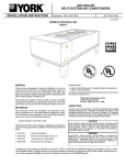
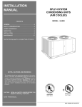
®
INSTALLATION MANUAL
SUNLINE 2000™ SPLIT-SYSTEM
CONDENSING UNITS
(AIR COOLED)
Supersedes: 035-15407-002-A-0304
035-15407-002-B-0404
MODELS H5CE090, H3CE120 & H1CE150
8.9 - 9.5 EER
GENERAL
These condensing units are designed for outdoor installation
on a roof or at ground level. Every unit is completely piped and
wired at the factory and is shipped ready for immediate installation. Only the liquid and suction lines to the evaporator coil, the
control wiring and the main power wiring are required to complete the installation. Each unit is dehydrated, evacuated, leak
tested and pressure tested at 450 psig before being pressurized with a holding charge of refrigerant-22 for shipment and/or
storage.
All controls are located in the front of the unit and are readily accessible for maintenance, adjustment and service. All wiring
(power and control) can be made through the front of the unit.
Refer to Table 7 for condenser cooling capacities and power requirements.
All forms may be ordered from:
Standard Register
Toll Free Telephone: 877-318-9675
Toll Free Fax: 877-379-7920
INSPECTION
As soon as a unit is received, it should be inspected for possible
damage during transit. If damage is evident, the extent of the
damage should be noted on the carrier's freight bill. A separate
request for inspection by the carrier's agent should be made in
writing. See Form 50.15-NM for more information.
REFERENCE
This instruction covers the installation and operation of the basic condensing unit. For information on the installation and operation of the evaporator blower units, please refer to the
matching air handler installation manual.
Additional information on the design, installation, operation and service of this equipment is available in the
following reference form.
• 550.23-N1.1V- Low Ambient Accessory
Replacement Parts:
• Refer to Parts Manual for complete listing of replacement
CAUTION
THIS PRODUCT MUST BE INSTALLED IN STRICT COMPLIANCE
WITH THE ENCLOSED INSTALLATION INSTRUCTIONS AND
ANY APPLICABLE LOCAL, STATE, AND NATIONAL CODES
INCLUDING, BUT NOT LIMITED TO, BUILDING, ELECTRICAL,
AND MECHANICAL CODES.
WARNING
INCORRECT INSTALLATION MAY CREATE A CONDITION
WHERE THE OPERATION OF THE PRODUCT COULD CAUSE
PERSONAL INJURY OR PROPERTY DAMAGE.
parts on this equipment.
Installer should pay particular attention to the words: NOTE, CAUTION and WARNING. Notes are intended to clarify or make the
installation easier. Cautions are given to prevent equipment damage. Warnings are given to alert installer that personal injury
and/or equipment damage may result if installation procedure is not handled properly.
035-15407-002-B-0404
TABLE OF CONTENTS
OPERATION
General................................................................................1
Reference ............................................................................1
Inspection ............................................................................1
Nomenclature ......................................................................2
Unit Operation - 7-1/2, 10 & 12-1/2 Ton ............................14
Safety Features .................................................................15
Maintenance ......................................................................15
Cleaning Condenser Surface .....................................15
Lubrication..................................................................15
Compressor Replacement .........................................15
INSTALLATION
Limitations ...........................................................................3
Location ...............................................................................3
Roof-Top Locations ......................................................3
Ground Level Locations ...............................................3
Rigging and Handling ..........................................................3
Clearances ..........................................................................4
Power and Control Wiring ...................................................4
Power Wiring ................................................................4
Control Wiring ..............................................................4
Compressor .........................................................................4
Compressor Crankcase Heater ...........................................4
Refrigerant Piping................................................................7
General Guidelines ......................................................7
Line Sizing....................................................................7
Service Valves..............................................................7
Extending The Service Ports ...............................................9
Installation ...........................................................................9
Evacuation and Charging ..................................................10
TABLES
No.
Description
Page
1
Unit Application Data..................................
3
2
Physical Data .............................................
4
3
Electrical Data ............................................
5
4
Suction Lines..............................................
8
5
Liquid Lines ................................................
8
6
Refrigerant Line Charge.............................
8
7
Cooling Cap's. & Power Requirements ......
9
FIGURES
No.
Description
Page
1
Center of Gravity ........................................
3
2
Typical Rigging...........................................
4
3
Typical Field Wiring with KES/KEU ............
5
4
Typical Field Wiring with PUC ....................
5
5
Unit Dimensions and Clearances...............
6
6
Four Point Loads........................................
7
7
Extending the Service Ports.......................
11
8
Charging Curve HCE090 ...........................
12
9
Charging Curve HCE120 ...........................
12
10
Charging Curve HCE150 ...........................
13
START-UP
Crankcase Heater .............................................................14
Pre-Start Check .................................................................14
Initial Start-Up....................................................................14
Secure Owner’s Approval..................................................14
PRODUCT NOMENCLATURE
H
4
C
E
0
9
0
A
2
5
PRODUCT CATEGORY
VOLTAGE CODE
H = Split-System Condensing Unit
PRODUCT GENERATION
1 = 1st Generation
2 = 2nd Generation
3 = 3rd Generation
4 = 4th Generation
2
25 = 208/230-3-60
46 = 460-3-60
58 = 575-3-60
NOMINAL COOLING
CAPACITY
PRODUCT IDENTIFIER
CE = Condensing Section
090 = 7-1/2 Tons
120 = 10 Tons
150 = 12-1/2 Tons
FACTORY INSTALLED HEAT
A = Not Applicable
Unitary Products Group
035-15407-002-B-0404
INSTALLATION
LIMITATIONS
These units must be installed in accordance with all national
and local safety codes. If no local codes apply, installation must
conform with the appropriate national codes. See Table 1 for
Unit Application Data. Units are designed to meet National
Safety Code Standards. If components are to be added to a
unit to meet local codes, they are to be installed at the dealer's
and/or the customer's expense.
LOCATION
TABLE 1 - UNIT APPLICATION DATA
MODEL
208/230-3-60
460-3-60
575-3-60
380/415-3-50
Ambient Air on Condenser Coil
Min. / Max.
Suction Pressure at Compressor and
Corresponding Temp. at Saturation
Min. / Max.
Voltage Variation1
Min. / Max.
1
HCE090,120 & 150
187 / 252
432 / 504
540 / 630
342 / 456
45°F / 115°F2
57.5 psig / 90.0 psig
32.0°F / 53.5°F
Rated in accordance with ARI Standard 110, utilization range “A”.
These units can operate at an ambient temperature of 120°F providing the wet bulb
temperature of the air entering the evaporator coil does not exceed 67°F.
NOTE: Refer to page 7 for refrigerant piping limitations.
2
Use the following guidelines to select a suitable location for these units.
Footers under the slab that extend below the frost line is recommended. Any strain on the refrigerant lines may cause a refrigerant leak. The slab should not be tied to the building
foundation because noise and vibration will telegraph into your
structure.
A unit can also be supported by concrete piers. These piers
should (1) extend below the frost line, (2) be located under the
unit's four corners, and (3) be sized to carry the entire unit
weight. Refer to Figure 1 and Table 2 for the center of gravity
and unit weight.
CAUTION: Care should be taken to protect the unit from tampering and unauthorized persons from injury.
Screws on access panels will prevent casual tampering. Additional safety precautions such as
fences around the unit or locking devices on the
panels may be advisable. Check local authorities
for safety regulations.
RIGGING AND HANDLING
Exercise care when moving the unit. Do not remove any packaging until the unit is near the place of installation.
Unit
7 Ton
10 Ton
Ton
A
42! "
70 &
% &
Dim. (in.)
B
C
31! "
19! "
32
30! "
32
' #&
D
11 15 &
$ 1. The condensing unit is designed for outdoor installation
only. The condenser fans are the propeller type and are not
suitable for use with duct work.
2. The condensing unit and the evaporator blower should be in-
stalled as close together as possible and with a minimum
number of bends in the refrigerant piping. Refer to “REFRIGERANT PIPING” for additional information.
3. The condensing unit should not be installed where normal
operating sounds may be objectionable. On either rooftop
or ground level installations, rubber padding can be applied
between the base rails and their supports to lessen any
transmission of vibration.
ROOF-TOP LOCATIONS
Be careful not to damage the roof. Consult the building contractor or architect if the roof is bonded. Choose a location with adequate structural strength to support the unit.
The condensing unit must be mounted on solid level supports.
The supports can be channel iron beams or wooden beams
treated to reduce deterioration.
A minimum of two (2) beams are required to support each unit.
The beams should: (1) Be positioned perpendicular to the roof
joists. (2) Extend beyond the dimensions of the unit to distribute
the load on the roof. (3) Be capable of adequately supporting the
entire unit weight. Refer to Center of Gravity and Point Load Figures and Physical Data Table for load distribution and weights.
These beams can usually be set directly on the roof. Flashing is
not required.
NOTE: On bonded roofs, check for special installation requirements.
GROUND LEVEL LOCATIONS
The units must be installed on a one-piece level concrete slab
with a minimum thickness of 4 inches. The length and width
should be at least 6 inches greater than the units overall base
dimensions. Refer to Figure 4.
Unitary Products Group
FIG. 1 - CENTER OF GRAVITY
Rig the unit by attaching nylon straps with hooks to the lifting
holes provided in the base rails. Spreaders, whose length exceeds the largest dimension across the unit, MUST be used
across the top of the unit if the rigging height above the top of
the unit is less than 5 feet. See Figure 2.
WARNING: Do not use straps under the unit or through the fork
lift slots for lifting purposes. Sharp metal edges can
damage the straps and could result in personal injury or equipment damage.
BEFORE LIFTING A UNIT, MAKE SURE THAT ITS WEIGHT
IS DISTRIBUTED EQUALLY ON THE STRAPS SO THAT IT
WILL LIFT EVENLY.
Units may also be moved or lifted with a fork-lift. Slotted openings in the base rails are provided for this purpose. The 7-1/2
ton unit may be lifted from either the LH or RH side - under the
unit.
LENGTH OF FORKS MUST BE A MINIMUM OF 42" for 7-1/2 ton
units or a MINIMUM OF 54" for 10 ton units when lifting across
the long dimension.
Remove the nesting brackets from the four corners on top of
the unit. All screws that are removed to take these brackets off
must be replaced on the unit.
3
035-15407-002-B-0404
Refer to Figure 4 for the location of the power wire access
opening through the front of the unit. This opening will require a
field-supplied conduit fitting.
The field-supplied disconnect switch must be suitable for an
outdoor location. Although it should be installed near the unit,
do NOT secure it to the unit cabinet.
5 F T . M IN .
Refer to Figure 3 for typical field wiring.
CONTROL WIRING
Refer to Figure 4 for the location of the control wire access
opening through the front of the unit.
Route the necessary low voltage control wires (18 AWG min.)
from the TB1 terminal block inside of the unit control box
through this access opening to the room thermostat and to the
evaporator blower motor controller.
FIG. 2 - TYPICAL RIGGING (7-1/2 Ton Shown)
The room thermostat should be located on an inside wall approximately 56" above the floor where it will not be subject to
drafts, sun exposure or heat from electrical fixtures or appliances. Follow manufacturer's instructions enclosed with thermostat for general installation procedure.
CLEARANCES
Refer to Figure 3 for typical field wiring.
All units require certain minimum clearances for proper operation and service. Refer to Figure 4 for these clearances.
COMPRESSOR
WARNING: Do not permit overhanging structures or shrubs to
obstruct condenser air discharge.
Additional height may be required for snow clearance if winter
operation is expected.
POWER AND CONTROL WIRING
Install electrical wiring in accordance with the latest National
Electrical Code (NFPA Standard No. 70) and/or local regulations. The unit should be grounded in accordance with these
codes.
POWER WIRING
Check the voltage of the power supply against the data on the
unit nameplate. Check the size of the power wire, the disconnect switch and the fuses against the data on Table 3.
NOTE: Copper conductors must be installed between the disconnect switch and the unit.
TABLE 2 - PHYSICAL DATA
Model
HCE
1
090
120
150
CAUTION: Do Not loosen compressor mounting bolts.
COMPRESSOR CRANKCASE HEATER (7-1/2 & 10
ton units only)
The compressor is equipped with a crankcase heater
to prevent refrigerant from mixing with crankcase oil
during the “OFF” cycle. The heaters will be energized
when the compressor is not running providing the unit
disconnect switch is closed.
CAUTION: Do not attempt to start the compressor without at
least eight hours of crankcase heat or compressor
damage will occur.
If a unit has just been installed or the unit disconnect switch has
been open for a long period of time, move the system switch on
the room thermostat to the “OFF” position before closing the
unit disconnect switch. Eight hours of crankcase heat are required to drive the liquid refrigerant out of the compressor before the compressor can be started.
Condenser
Compressor
(Tandem on
150 only)
Fan (Propeller)
Rating
Cap.
Dia.
Qty.
(Tons) (Stages)
(in.)
Nom.
CFM
7-1/2
10
12-1/2
4677
8034
7950
1
1
1
Units are shipped with compressor mountings factoryadjusted and ready for operation.
1
2
2
24
24
24
Fan Motor1
Blades
2
Pitch Qty. HP RPM Rotation
(Deg.)
3
29
1 3/4 1120
CW
3
27
2 1/2 1110 CCW
3
27
2 1/2 1110 CCW
Qty.
Coil3
Face
Area
(Ft.2)
18.7
23.8
23.8
Unit
Weight
(Lbs.)
Charge,
Lbs.-Oz.
(Refrigerant-22)
Finned
Rows
Length
Ship. Oper. Holding
High
(in.)
90
30 365 360 1 - 12
96
36 435 430
2-4
96
36 515 510
2-4
Oper.4
12 - 05
18 - 6
19 - 5
These PSC motors are directly connected to the condenser fans and have inherent protection, ball bearings and a 48 frame.
When viewing the shaft end of the motor.
3
These condenser coils have 2 rows of 3/8” OD copper tubes and 16 aluminum fins per inch.
4
Includes matched indoor blower unit but no piping. Refer to Table 6 for refrigerant line charge.
5
Add an additional 1 lb. charge when used with KEU120 (10 ton) indoor units.
2
4
Unitary Products Group
035-15407-002-B-0404
SIZE POWER WIRING,
NOTE: USE COPPER
CONDUCTORS ONLY
DISCONNECT SWITCH, AND
FUSING PER ELECTIRICAL
DATA TABLE
31 3
1 11 12 3
WIRE IN ACCORDANCE WITH
ALL LOCAL AND NATIONAL
ELECTRICAL CODES
!" # $ %& '(%%')" )( )*
"+,,- )$, %.!* (% '.% /
$(+)" " $')!- $(, ) '(%"%* %&
+% ) )( ) )$,(*).) "* $"0
FIG. 3 - TYPICAL FIELD WIRING WITH KES/KEU AIR HANDLER
TERMINAL STRIP
TERMINAL STRIP
ON FURNACE
TB1 ON
PMUB30N19031
HEHB090
R
R
Y
Y1
G
B
W
THERMOSTAT*
TERMINALS
R
Y
G
W
C
COIL
24-VOLT
ISOLATION RELAY
(FIELD SUPPLIED)
*24-volt thermostat
2TH13700424 with Subbase 2TB17700424.
FIG. 4 - TYPICAL WIRING WITH PUC FURNACE
TABLE 3 - ELECTRICAL DATA
Model
HCE
090
120
150
1
2
Voltage
Code
25
46
58
25
46
58
25
46
58
Compressor
Power
Supply
RLA
208/230-3-60
460-3-60
575-3-60
208/230-3-60
460-3-60
575-3-60
208/230-3-60
460-3-60
575-3-60
25.6
12.8
10.2
42.0
19.2
13.8
41.4
20.0
16.4
Condenser Fan Motor
LRA
Power
Supply
HP
Qty.
FLA
Unit
Ampacity
(Amps)
190
95
75
239
125
80
312
150
108
208/230-1-60
460-1-60
575-1-60
208/230-1-60
460-1-60
460-1-602
208/230-1-60
460-1-60
460-1-602
3/4
3/4
3/4
1/2
1/2
1/2
1/2
1/2
1/2
1
1
1
2
2
2
2
2
2
3.03
1.6
1.8
2.7
1.6
1.3
3.0
1.8
1.8
35.1
17.6
14.6
51.8
24.7
18.0
52.6
26.1
21.3
Max.
Fuse
Size1
(Amps)
60
30
20
70
35
25
70
35
30
Dual element.
Unit includes a 575 to 460-volt transformer.
Unitary Products Group
5
035-15407-002-B-0404
C O N T R O L B O X
A C C E S S
4 2 -3 /4
(1 0 8 6 )
3 1 -3 /4
(8 0 7 )
A IR
O U T
A IR
IN
3 2 -1 /2
(8 2 6 )
HCE090
(7-1/2 TON)
7 /8 " D IA .
C O N T R O L W IR IN G
E N T R Y
5
(1 2 7 )
4 -1 /8
(1 0 5 )
2 (5 1 )
5 (1 2 7 )
G U A G E
L IN E
A C C E S S
4 -5 /8 (1 1 8 )
2 5 -3 /4
(6 5 5 )
1 -3 /8 " (3 4 .9 ) D IA .
P O W E R W IR IN G
E N T R Y
7 /8 " (2 2 .2 ) K N O C K O U T
A C C E S S O R Y W IR IN G
E N T R Y
CLEARANCES
Overhead (Top)1
Front
(Piping and Access Panels)
Left Side
Right Side
Rear
Bottom2
120"
1 -1 /8 " (2 8 .6 ) O D
S U C T IO N L IN E
C O M P R E S S O R A N D
C O N D E N S E R F A N M O T O R
A C C E S S
2 -1 /2
(6 .4 )
1 0 -1 /8
(2 5 8 )
4 -1 /2
(1 1 5 )
1 /2 " (1 2 .7 ) O D
L IQ U ID L IN E
30"
All dimensions are in inches. They are
subject to change without notice.
Certified dimensions will be provided
upon request.
24"
24"
24"
0"
1
Units must be installed outdoors. Overhanging structures or
shrubs should not obstruct condenser air discharge.
2
Adequate snow clearance must be provided if winter operation is expected.
HCE120
(10 TON)
H1CE150
(12-1/2 Ton)
& ''
! !
# "
!
$
!
%
" # "
FIG. 5 - UNIT DIMENSIONS AND CLEARANCES
6
Unitary Products Group
035-15407-002-B-0404
*
)
)
HCE090
+
,
*
HCE120 & 150
,
+
UNIT
4- POINT LOAD (LBS)
TOTAL
A
B
C
D
120
430
90
114
127
99
150
510
111
152
143
104
FIG. 6 - FOUR POINT LOADS
REFRIGERANT PIPING
GENERAL GUIDELINES
Many service problems can be avoided by taking adequate
precautions to provide an internally clean and dry system and
by using procedures and materials that conform with established standards.
Use hard drawn copper tubing where no appreciable amount of
bending around pipes or other obstructions is necessary. Use
long radius ells wherever possible with one exception—short
radius ells for the traps in all suction risers. If soft copper is
used, care should be taken to avoid sharp bends which may
cause a restriction.
Pack fiber glass insulation and a sealing material such as permagum around refrigerant lines where they penetrate a wall to
reduce vibrations and to retain some flexibility.
Support all refrigerant lines at minimum intervals with suitable
hangers, brackets or clamps.
Braze all copper to copper joints with Silfos-5 or equivalent
brazing material. Do not use soft solder.
Insulate all suction lines with a minimum of 1/2" ARMAFLEX or
equal. Liquid lines exposed to direct sunlight and/or high temperatures must also be insulated.
Never solder suction and liquid lines together. They can be
taped together for convenience and support purposes, but they
must be completely insulated from each other.
A filter-drier MUST be installed in the liquid line of every system
to prevent dirt and moisture from damaging the system. A
properly-sized filter-drier is shipped with each condensing unit
for field installation near the evaporator coil. The filter-drier and
is taped to the top of the compressor.
NOTE: Installing a filter-drier does not eliminate the need for
the proper evacuation of a system before it is
charged.
A moisture indicating sight-glass may be field installed in the
liquid line(s) between the filter-drier and the evaporator coil.
The moisture indicating sight-glass can be used to check for
excess moisture in the system or used as a visual means to
verify refrigerant charge.
LINE SIZING
When sizing refrigerant lines for a split-system air conditioner,
check the following:
Unitary Products Group
1. Suction line pressure drop due to friction
2. Liquid line pressure drop due to friction
3. Suction line velocity for oil return, and
4. Liquid line pressure drop due to static head.
NOTE: Never base refrigerant line sizes on the O.D. of the
suction and liquid connections on the unit.
Tables 4 and 5 list friction losses for both the suction and liquid
lines on the system. Table 6 shows the amount of refrigerant
charge required per foot of refrigerant line.
When the evaporator coil is below the condensing unit, the suction line must be sized for both pressure drop and for oil return.
For certain piping arrangements, different suction line sizes
may have to be used. The velocity of the suction gas must always be great enough to carry oil back to the compressor.
When the condensing unit is below the evaporator coil, the liquid line must be designed for the pressure drop due to both friction loss and vertical rise. If the total pressure drop exceeds 40
psi, some refrigerant may flash before it reaches the thermal
expansion valve. This flashing will not only cause erratic valve
operation and poor system performance, but could also damage the expansion valve.
SERVICE VALVES
These condensing units have service valves on both the compressor suction connection and the liquid line leaving the condenser coil.
The liquid and suction line service valves are shipped from the
factory front-seated and closed with the valve stem in the maximum clockwise position.
Both of the service valves have a 1/4" male flare access port for
evacuating, charging and pressure checking the system.
NOTE: Never remove a cap from an access port unless the
valve is fully back-seated with its valve stem in the
maximum counter-clockwise position because the refrigerant charge will be lost. ALWAYS USE A REFRIGERATION VALVE WRENCH TO OPEN AND
CLOSE THESE SERVICE VALVES.
7
035-15407-002-B-0404
TABLE 4 - SUCTION LINES
1,2
Model
Designation
Nominal
Capacity
(Tons)
Refrigerant
Flow Rate3
(Lbs./Min.)
HCE090
7-1/2
22
HCE120
10
30
HCE150
12-1/2
37
Type L
Copper Tubing
(Inches O.D.)
1-1/8
1-3/8
1-5/8
1-1/8
1-3/8
1-5/8
1-3/8
1-5/8
Refrigerant
Gas
Velocity
(FT./Min.)
2050
1680
1140
3500
2280
1560
2510
1800
Friction
Loss4,5
(PSI/100 Ft.)
4.3
1.6
0.7
8.0
2.8
1.2
3.9
1.5
1All horizontal suction lines should be pitched at least 1 inch every 20 feet in the direction of the refrigerant flow to aid the return of oil to the compressor.
2
Every vertical suction riser greater than 3 feet in height should have a “P” trap at the bottom to facilitate the return of oil to the compressor. Use short radius fittings for these traps.
3
Based on Refrigerant-22 at the nominal capacity of the condensing unit, a suction temperature of 40°F and a liquid temperature of 105°F.
4
Although suction lines should be sized for a friction loss equivalent to a 2°F change in saturation temperature (or approximately 3 psi), sizing the lines for the proper return of oil
is more important.
5
These friction losses do not include any allowances for valves or fittings.
TABLE 5 - LIQUID LINES
1
2
3
Model
Designation
Nominal
Capacity
(Tons)
Refrigerant
Flow Rate1
(Lbs./Min.)
HCE090
7-1/2
22.0
HCE120
10
30
HCE150
12-1/2
37
Pressure Drop3
Type L
Copper Tubing
(Inches O.D.)
Friction2
(PSI/100 Ft.)
1/2
5/8
5/8
3/4
5/8
3/4
11.0
3.5
5.8
2.3
8.0
3.0
Vertical
Rise
(PSI/Ft.)
0.5
0.5
0.5
0.5
Based on Refrigerant-22 at the nominal capacity of the condensing unit, a liquid temperature of 105°F and a suction temperature of 40°F.
These friction losses do not include any allowances for a strainer, filter-drier, solenoid valve, isolation valve or fittings.
The total pressure drop of the liquid line for both friction and vertical rise must not exceed 40 PSI. If the pressure drop exceeds 40 PSI, the liquid refrigerant could flash before it reaches the
expansion valve. This flashing will not only cause erratic valve operation and poor system performance, but could also damage the expansion valve.
NOTE: Maximum line length for HCE150 is 150 feet.
TABLE 6 - REFRIGERANT-22 LINE CHARGE1
Liquid Line2
Inches, O.D.
Suction Line2
Inches, O.D.
8
1/2
5/8
3/4
1-1/8
1-3/8
1-5/8
0.070 lb./ft.
0.113 lb./ft.
0.167 lb./ft.
0.009 lb./ft.
0.013 lb./ft.
0.019 lb./ft.
NOTE: Add the operating charge of the condensing unit, the evaporator coil and
the refrigerant lines to determine the total refrigerant charge of the system.
1
2
Charges are based on 40°F suction temperature and a 105°F liquid temperature.
Type “L” copper tubing.
Unitary Products Group
035-15407-002-B-0404
TABLE 7 - COOLING CAPACITIES AND POWER REQUIREMENTS
Model
HCE
090
120
150
Suction Press. & Corresponding
Temp. @ Saturation
65
PSIG
MBH
KW*
°F
61.6
35
90
6.1
68.5
40
101
6.3
76.0
45
110
6.5
84.0
50
120
6.6
61.6
35
123
7.7
68.5
40
134
8.0
76.0
45
145
8.2
84.0
50
156
8.4
61.6
35
140
9.4
68.5
40
151
9.6
76.0
45
165
9.9
84.0
50
178
10.2
75
MBH
88
96
109
115
117
128
139
150
133
144
156
169
Temperature of Air on Condenser Coil, °F
85
95
105
KW*
MBH
KW*
MBH
KW*
MBH
KW*
6.7
81
7.2
77
7.9
74
8.6
6.8
91
7.4
87
8.1
82
8.9
7.0
101
7.6
95
8.4
90
9.1
7.2
109
7.8
104
8.6
99
9.4
8.4
112
9.1
106
9.9
100
10.8
8.6
122
9.3
116
10.1
110
11.0
8.8
132
9.5
126
10.4
120
11.3
9.1
143
9.8
136
10.6
129
11.5
10.4
127
11.3
119
12.6
112
13.8
10.6
137
11.5
129
12.8
122
14.1
10.9
148
11.8
140
13.1
132
14.4
11.2
159
12.1
151
13.4
142
14.8
115
MBH
KW*
68
9.5
77
9.7
85
10.0
93
10.3
95
11.8
104
12.1
113
12.3
123
12.5
105
15.1
114
15.4
124
15.8
134
16.1
* Includes compressor and condenser fan motor(s).
EXTENDING THE SERVICE PORTS
(Refer to Fig 7.)
1. Loosen the screws securing the service ports in shipping
position.
2. Push the service ports through the corner post.
3. Tighten the screws to secure the service ports for installation.
INSTALLATION
Since the condensing units are shipped with a holding charge
of refrigerant-22, they can be checked for a refrigerant leak by
depressing the stem on either of the service ports that extend
through the cabinet. As soon as some internal pressure is relieved release the stem. DO NOT release the entire holding
charge.
If the unit has already lost its holding charge, it should be leak
tested and the necessary repairs should be made. If the unit
has maintained its holding charge, you can assume that it has
no leaks and proceed with the installation.
CAUTION: Dry nitrogen should always be supplied through a
connection while it is being brazed or unbrazed because the temperature required to make or break a
brazed joint is sufficiently high to cause oxidation
of the copper unless an inert atmosphere is provided. The flow of nitrogen should be continued until the joint has cooled.
When making a braze connection, wrap a wet rag
around all tubing inside the unit to help prevent
damage to other components.
WARNING: The dry nitrogen should always be supplied
through a pressure regulating valve.
On HCE090 models only, remove the 4-1/2" x 4-1/2" patch
plates from the piping access panel on the front of the unit to expose the refrigerant connections.
Before installing the liquid line between the condensing unit
and the evaporator coil, prepare as follows:
1. Burnish the external surfaces of the liquid connection on
the condensing unit and the end of the field-supplied piping
for the liquid line.
NOTE: Clean surfaces are essential for a well-brazed connection.
2. Carefully clean the internal surfaces of the above. Any particles left on these surfaces may lead to a future system
malfunction.
Unitary Products Group
NOTE: Use only copper tubing that has been especially
cleaned and dehydrated for refrigerant use. If the
tubing has been open for an extended period of
time, it should be cleaned before being used.
The liquid line connections can now be brazed while maintaining a minimum flow of dry nitrogen through the piping as follows:
1. Remove the cap from the 1/4" access port on the liquid line
service valve.
2. Connect a supply of dry nitrogen to this access port.
NOTE: The filter-drier should be installed in the liquid line as
close to the evaporator coil as possible.
Do not allow the filter-drier to be exposed to the atmosphere for an extended period of time. Once it absorbs
moisture from the atmosphere, it loses its
effectiveness.
3. The matched air handlers are shipped with a small R-22
charge and they should be checked for leaks before installation. Drill a small hole through the sealing cap or disc in
both the liquid and suction connection. If there is a pressure release, the evaporator has no leaks and you can proceed with installation. If the charge has been lost, the coils
should be leak tested and the necessary repairs made.
4. Move the dry nitrogen supply from the access port on the
liquid line service valve of the condensing unit to the hole
through the suction disc on the evaporator coil.
5. Unbraze the coil's liquid line disc while maintaining a flow of
dry nitrogen across the connection and through the hole in
the liquid line disc.
NOTE: If the liquid line has a solenoid valve, the valve
should be opened manually to permit the nitrogen
to flow freely.
6. After the disc has been removed, burnish the external surfaces and clean the internal surfaces as outlined above.
7. Move the dry nitrogen supply back to the access port on the
liquid line service valve.
8. Braze the liquid line to the liquid connection on the evaporator coil while maintaining a minimum flow of dry nitrogen
through the liquid line, the evaporator coil and the hole in
the suction disc.
9. Unbraze the disc on the suction connection of the evaporator coil while maintaining the flow of dry nitrogen.
9
035-15407-002-B-0404
10. After the disc has been removed, burnish the external surfaces and clean the internal surfaces as outlined above.
The suction piping can now be brazed to the suction
connection on the evaporator coil while maintaining a
minimum flow of dry nitrogen.
Before brazing the suction line to the condensing unit;
1. Move the dry nitrogen supply to the access port on the suction service valve of the condensing unit.
2. Burnish the external surfaces and clean the internal surfaces of both the suction connection and the suction piping.
The suction line can now be brazed to the suction connection on the condensing unit while maintaining the
flow of dry nitrogen.
After the liquid and suction lines have been installed,
the system should be evacuated and charged.
EVACUATION AND CHARGING
To continue charging refrigerant, open the liquid and the suction line service valves fully. Turn the stem of the liquid service
valve clockwise 1/4 turn to open its access port for reading
pressure.
Start the compressor (after 8 hours of crankcase heat), turn the
stem of the suction line service valve clockwise 1/4 turn to open
its service port and continue to charge refrigerant gas through
this suction access port until you meet the conditions shown on
the charging curve, Fig. 8-10.
Open the liquid and vapor line service valves fully to close their
access ports after the system has been charged.
Alternate Charging Methods
If you are starting a unit when the ambient temperature is
higher or lower than those shown in Fig. 8-10, either of the following methods may be used.
Method 1: Determine the total weight of the refrigerant for the
total system by adding the required charge for the
outdoor unit, the indoor unit and the refrigerant
lines using information in Tables 2 (Physical Data)
and 6 (Refrigerant Line Charge).
Using the charging procedures outlined above,
weigh the required amount of refrigerant charge
into the unit.
With the liquid and suction line service valves closed, connect a
vacuum pump through a charging manifold to the access ports
on both the liquid and suction line service valves.
Note:
The vacuum pump connection should be short and
no smaller than 3/8" O.D.
Method 2: Install a field supplied moisture indicating sight
glass in the liquid line between the filter-drier and
the evaporator coil.
The refrigerant lines and the evaporator coil can now be evacuated to 500 Microns without disturbing the charge in the condenser coil or the compressor.
After proper evacuation and dehydration, charge refrigerant
through the access port on the liquid line service valve allowing
the vacuum to draw in as much refrigerant as possible.
Using the charging procedure outlined above,
charge refrigerant until the moisture indicating
sight glass is clear. Add approximately 1 extra
pound of refrigerant for the 090 and 120 or 3 extra
pounds for the 150 to assure a liquid refrigerant
seal at the expansion valve under all operating
conditions. Block the flow of the condenser air, if
necessary, to assure a head pressure of 280 psig
during the charging procedure.
CAUTION: Do not charge liquid refrigerant through the compressor suction connection.
CAUTION: Do not attempt to start the compressor without at
least 8 hours of crankcase heat or compressor
damage will occur.
10
Note:
The installer should return to the job to verify the
operating charge when the ambient temperature is
within the conditions shown in Fig. 8-10.
Unitary Products Group
035-15407-002-B-0404
FIG. 7 - EXTENDING THE SERVICE PORTS
Unitary Products Group
11
035-15407-002-B-0404
FIG. 8 - CHARGING CURVE HCE090
FIG. 9 - CHARGING CURVE HCE120
12
Unitary Products Group
035-15407-002-B-0404
FIG. 10 - CHARGING CURVE HCE150
Unitary Products Group
13
035-15407-002-B-0404
CRANKCASE HEATER
START-UP
The crankcase heaters must be energized at least 8 hours before starting the compressor. To energize the crankcase heaters, the main disconnect switch must be closed. During this 8
hour period, the system switch on the room thermostat must be
“OFF” to prevent the compressor from starting.
CAUTION: DO NOT ATTEMPT TO START THE COMPRESSOR WITHOUT AT LEAST 8 HOURS OF CRANKCASE HEAT OR COMPRESSOR DAMAGE WILL
OCCUR.
Make sure that the bottom of the compressor is warm to the
touch to prove crankcase heater operation.
PRE-START CHECK
Before starting the unit, complete the following check list:
1. Have sufficient clearances been provided?
2. Has all foreign matter been removed from the interior of the
unit (tools, construction or shipping materials, etc.)?
3. Have the condenser fans been rotated manually to check
for free rotation?
4. Are all wiring connections tight?
5. Does the available power supply agree with the nameplate
data on the unit?
6. Is the control circuit transformer set for the proper voltage?
7. Have the fuses, disconnect switch and power wire been
sized properly?
8. Are all compressor hold-down nuts properly secured?
9. Are any refrigerant lines touching each other or any sheet
metal surface? Rubbing due to vibration could cause a refrigerant leak.
10. Are there any visible signs of a refrigerant leak, such as oil
residue?
11. Is any electrical wire laying against a hot refrigerant line?
INITIAL START-UP
1. Supply power to the unit through the disconnect switch at
least 8 hours prior to starting the compressor.
2. Move the system switch on the thermostat to the AUTO or
COOL position.
3. Reduce the setting of the room thermostat to energize the
compressor.
4. Check the operation of the evaporator unit per the manufacturer's recommendations.
5. With an ammeter, check the compressor amps against the
unit data plate.
6. Check for refrigerant leaks.
7. Check for any abnormal noises and/or vibrations, and make
the necessary adjustments to correct (e.g. fan blade(s)
touching shroud, refrigerant lines hitting on sheet metal, etc.)
8. After the unit has been operating for several minutes, shut off
the main power supply at the disconnect switch and inspect
all factory wiring connections and bolted surfaces for tightness.
CAUTION: DO NOT ATTEMPT TO START THE COMPRESSOR WITHOUT AT LEAST 8 HOURS OF CRANKCASE HEAT OR COMPRESSOR DAMAGE WILL
OCCUR.
SECURE OWNER'S APPROVAL: When the system is functioning properly, secure the owner's approval. Show him
the location of all disconnect switches and the thermostat. Teach him how to start and stop the unit and how to adjust
temperature settings within the limitations of the system.
OPERATION
UNIT OPERATION - 7-1/2, 10 & 12-1/2 TON
When the external control calls for cooling at terminal Y1:
1. The system controller (SC) is energized. The system controller starts the compressors and enables the condenser
fans by energizing contactor 1M (and 2M on the 12-1/2 ton,
208/230 volt models).
The single condenser fan is energized with the compressor
on the 7-1/2 ton models.
Condenser fan motor #1 is energized with the compressors
on the 10 and 12-1/2 ton models while fan #2 is enabled
with compressor operation. Fan motor #2 operation is controlled through the Ambient Temperature Switch (ATS)
which will de-energize the motor when the ambient temperature falls below 70°F.
2. Safety Lockout: The system controller (SC) has a lockout
circuit to prevent compressor short-cycling on a safety control with automatic reset. If the high or low refrigerant pressure switches (HP or LP) open, the SC will enter lockout
mode.
14
SC provides a 90 second bypass of the low pressure switch
LP to prevent nuisance lockouts during unit start-up.
A malfunction light (24V, 2 A max. resistive load) can be energized through SC, by connecting the light between terminals X and B on TB1. Terminal X will energize when SC
locks out.
3. Unit is equipped with an anti-short cycle timer to prevent
two successive compressor starts within 5 minutes. If the
compressor fails to start with a call for cooling and SC is not
locked out, wail at least 6 minutes for the anti-cycle timer to
reset.
NOTE: To reset the unit after a lockout:
A. Turn the system switch on the thermostat to the “OFF”
position and back to the “COOL” position.
OR
B. Increase the set point of the room thermostat above the
temperature in the conditioned space and return it to its
original setting.
Unitary Products Group
035-15407-002-B-0404
If the unit continues to be shut down by one of its safety controls, service should be called to determine the cause of the
problem. Repeatedly resetting the lockout circuit may
damage the unit.
The following accessories are available to provide low ambient operation to 0°F.
SAFETY FEATURES
1. All condenser fan motors have inherent protection with
automatic reset.
2. Every compressor is internally protected against over current,
excessive temperature and primary single phasing.
This protection is provided by a line break motor protector that
is mounted inside the compressor housing and is connected
between each winding and the common terminal.
3. Every compressor (except HCE150 scrolls) is protected by
crankcase heaters to prevent refrigerant from accumulating in the crankcases of the compressor during an “OFF”
cycle.
Unitary Products Group
4. All condenser fan motors and the secondary of every transformer is grounded.
5. Every unit is protected by both a high and a low pressure
control, and these controls are self-contained. Since they
are mounted directly on the access connections and wired
back to the control panel, there are no capillary lines to be
damaged.
MAINTENANCE
CLEANING CONDENSER SURFACE
Dirt should not be allowed to accumulate on the condenser
coils or other parts in the condenser air circuit. Clean as often as necessary with a brush, vacuum cleaner attachment
or other suitable means.
LUBRICATION
The fan motors for these condensing units are equipped
with factory lubricated and sealed ball bearings. They do
not require any maintenance.
COMPRESSOR REPLACEMENT
Contact the local UPG Distribution Center for compressor
or parts.
15
Unitary Products Group
5005 York Drive, Norman, Oklahoma 73069
Subject to change without notice. Printed in U.S.A
Copyright © 2004 by York International Corporation. All Rights Reserved.
035-15407-002-B-0404
Supersedes: 035-15407-002-A-0304