1
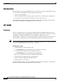
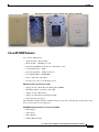
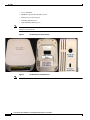
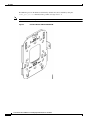
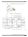
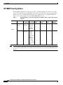
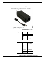
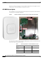
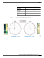
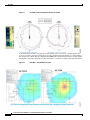
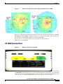
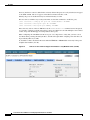
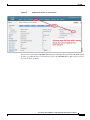
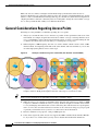
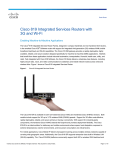
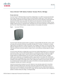
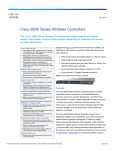
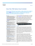
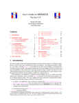
Cisco Aironet Series 702W Access Point Deployment Guide, Release 7.6.100.120 Last Updated: May, 2014 Cisco Systems, Inc. www.cisco.com Introduction Introduction This document covers the Cisco 702W Series Access Points theory of operation and installation as part of a Cisco Wireless LAN (WLAN) solution. Subjects related include: • Overview of the AP-702W. • Physicals / Hardware details, mounting options, bracket choices, and installation considerations. • Powering options, antenna patterns, switched ports, AP placement, and so on. This document is intended for trained and experienced technical personnel familiar with the existing Cisco Wireless Networking Group (WNG) product line and features. AP-702W Overview The Cisco AP-702W Series Access Point targets Multi-Dwelling-Unit (MDU) deployments, such as customers requiring support for Higher Education, Hospitality, college dorm-rooms, K-12 classrooms, and healthcare, seeking a high-performance in-room Wireless + Wired Access Device. The AP-702W is a wall plate Access Point (AP) designed to combine the features of an AP and a four port switch into a single unit with a small footprint targeting education and hospitality markets. Note Do not confuse AP-702W with AP-702i, which is a conventional AP designed for ceiling mounting and does not have additional Ethernet ports for device connectivity. AP-702w features include: • Combined hardware switch and wireless AP. • 4 x 10/100/1000BASE-T local Ethernet ports for wired device connectivity. • 1 local Ethernet port includes Power-Over-Ethernet (PoE) out. • 1 x 10/100/1000BASE-T Power-Over-Ethernet (PoE) uplink port. • 802.11n 2x2:2 simultaneous dual band 2.4 GHz and 5 GHz support. • Compact form factor designed for in-room installations. • Integrated 2.4 GHz 2 dBi and 5 GHz 4 dBi antennas. • Small footprint 6 x 4 x 1.6 inches. The AP-702W, while similar to the Cisco AP-700 series with regards to performance, is different and embodies a wall mount design and should not be ceiling mounted. Cisco Aironet Series 702W Access Point Deployment Guide, Release 7.6.100.120 2 AP-702W Figure 1 Unit can be installed in less than a minute with a simple screwdriver. Cisco AP-702W Features Cisco Aironet 702W Series: • Wi-Fi Standards - 802.11a/b/g/n • Max Data Rate - 300 Mbps per radio • Radio Design MIMO: Spatial Stream - Dual-Radio, 2x2:2 • Local Ethernet Ports - 4xGE • Powering Capability - 1xGE port PoE out • Data Uplink (Mbps) - 10/100/1000 • Power - 802.3af/at, AC Adapter • Security lock - Torx screw, Kensington lock Additional technical specifications include: • Support for Cisco Radio Resource Management (RRM) • Maximum number of clients per AP = 200 • Support for Cisco Band Select • Support for VideoStream and Adaptive wIPS • Rogue AP detection support The AP-702W is similar in features and functionality to other Cisco APs with the exception that at first release a few features are not supported. AP-702W Non-Supported features as of version 7.6.100.120: • Mesh Support • Autonomous • Office Extend • Explicit Beam-forming Cisco Aironet Series 702W Access Point Deployment Guide, Release 7.6.100.120 3 AP-702W Note Note • Cisco ClientLink • IGMP Snooping for IP TV multicast Join • Managed local-switched ports • Tunneling Ethernet Ports • Split-Tunneling Ethernet ports Many of these features are targeted for later releases. Please check the release notes of the current software for more details. Figure 2 AP-702 Physicals Characteristics Figure 3 AP-702 Ethernet Switched Ports LAN4 can provide PoE out. Cisco Aironet Series 702W Access Point Deployment Guide, Release 7.6.100.120 4 AP-702W Figure 4 The AP may be secured into the bracket with a hidden tamper resistant screw A sticker covers the screw to prevent detection. Also, a Kensington lock may be used as well. AP-702W Installation As mentioned in Figure 1, the AP-702W is designed to be mounted on an existing electrical box or network outlet box. Because of the vent holes on the device, it is not designed for ceiling mounting but may be mounted on the wall close to the ceiling so long as there is at least a 3-inch gap between the top of the unit and the ceiling for heat dissipation. The default wall bracket is designed to allow the four switched ports to be accessible for downstream devices. It is not recommended (or supported) to use the downstream switched ports to connect additional APs or other heavy upstream traffic devices such as additional switches and so on. Cisco Aironet Series 702W Access Point Deployment Guide, Release 7.6.100.120 5 AP-702W The Ethernet ports in AP-702W are disabled by default and can be enabled by using the enable_port port id command, where port ID can range from 1 - 4. Note By default, the 4 switched ports on the AP are disabled. Figure 5 Standard Bracket AIR-AP-BRACKET-W Cisco Aironet Series 702W Access Point Deployment Guide, Release 7.6.100.120 6 AP-702W Figure 6 Optional AIR-AP-BRACKET-WP can be used to secure the four switched ports Figure 7 Physical Dimensions for the AP-702W Bracket in Millimeter Cisco Aironet Series 702W Access Point Deployment Guide, Release 7.6.100.120 7 AP-702W AP-702W Powering Options The AP-702W is designed to accept power via Power over Ethernet (PoE) or by using a local “brick” style power supply. Because the AP-702W has the ability to provide PoE out on port #4, the unit does draw in an excess of 15.4 Watts (802.3af) specification, and therefore it is recommended that PoE+, 802.3at or local power supply Cisco part number AIR-PWR-C be used. Table 1 702W Note PoE Requirements – if you are using PoE out on PORT 4, PoE+ or local power supply is required AP PoE Budget Description Functionality (Watts) 802.3af No PoE+ 702W - Out 2x2:2 (both 16.1 802.3at of the box bands) all ports on including PoE OUT Yes PoE 802.3af 702W - Out PoE OUT on 15.4 of the box Port 4 is disabled (port is enabled, but without PoE). This is the green port on AP 2x2:2 in both bands. 802.3at PoE+ PWRINJ4 Yes N/A N/A If the unit is powered by 802.3at (PoE+) then the device draws 16.1 Watts and can deliver PoE out of port 4 at 7 Watts output. If 802.3af (15.4 Watts) is desired, then the local power supply AIR-PWR-C must be used. Cisco Aironet Series 702W Access Point Deployment Guide, Release 7.6.100.120 8 E-PoE Yes AP-702W Figure 8 AIR-PWR-C is the Local Power Supply (Do not use AIR-PWR-A or AIR-PWR-B) Table 2 Output Input Cisco Part # AIR-PWR-C=, higher current than AIR-PWR-B=, needed for POE out port on 702W DC Voltage 48V Rated Current 0.84A Current Range 0.1 ~ 0.84A Rated Power (max.) 40W Ripple and Noise (max.) 240mVp-p Voltage Range 80 ~ 264VAC 113 ~ 370VDC Frequency Range 47 ~ 63HZ Efficiency (Typ.) 91% AC Current (Typ.) 1 A / 115VAC 0.5A / 230VAC INRUSH Current (Typ.) 65A / 230VAC Cisco Aironet Series 702W Access Point Deployment Guide, Release 7.6.100.120 9 AP-702W Earlier Cisco-Aironet power supplies are rated at 48 VDC @ 380 mA. These earlier supplies do not have enough current to allow the AP-702W to provide PoE out on port 4. AP-702W Antenna System The AP-702W has two integrated dual band antennas designed for best performance when mounted to an electrical box in a wall mount configuration. Figure 9 Antenna 1 and Antenna 2 mounted on the Top and Left Side of the AP-702W Avoid mounting the AP in locations where metal objects would be near the antennas. The antenna gain is 2 dBi @ 2.4 GHz and 4 dBi @ 5 GHz designed to radiate in a front Omni-directional pattern with 25 dB of isolation between bands. Table 3 Technical Specifications of the AP-702W Antenna System Operating Frequency Ranges 2.4 - 2.5 GHz 5.15 - 5.85 GHz Nominal Input Impedance 50 Ohms 50 Ohms VSWR 2:1 Max 2:1 Max Peak Gain 2 dBi 4 dBi Cisco Aironet Series 702W Access Point Deployment Guide, Release 7.6.100.120 10 AP-702W Table 3 Figure 10 Technical Specifications of the AP-702W Antenna System Azimuth Plane 3 dB Beamwidth 130 degree 80 degree Elevation Plane 3 dB Beamwidth 180 degree 100 degree Antenna to Antenna Isolation > 30 dB > 33 dB Typical Front-to-Back Ratio 8 dB 10 dB AP-702W - Antenna Radiation Patterns for 2.4 GHz Cisco Aironet Series 702W Access Point Deployment Guide, Release 7.6.100.120 11 AP-702W Figure 11 AP-702W - Antenna Radiation Patterns for 5 GHz As mentioned, the AP-702 is designed for wall mounting and so it may have a slightly smaller cell coverage area than a conventional AP that is typically mounted physically higher on a ceiling. This is fine, because Cisco Radio Resource Management (RRM) will learn and properly balance out the channel assignments, and clients will roam smoothly when there is a mixture of ceiling and wall mounted APs. Figure 12 Heat Map - AP-702W and AP-3700 Cisco Aironet Series 702W Access Point Deployment Guide, Release 7.6.100.120 12 AP-702W Figure 13 Channel Assignments and Power Settings Determined by Cisco RRM Roaming, channel assignments, and RF power all function well with the AP-702W. Its antenna technology comprising two transmit radios and two receive radios in each band called 2x2 in a Multiple Input Multiple Output (MIMO) configuration support two spatial streams (2SS) together referenced as 2x2:2. For more on the benefits of 802.11n, see the following URL: http://www.cisco.com/c/en/us/solutions/collateral/enterprise-networks/802-11n/ white_paper_c11-513840.html AP-702W Switched Ports Figure 14 Ethernet Switched Ports AP-702W The 4 x 10/100/1000BASE-T local Ethernet ports support half and full duplex mode, auto-negotiation, and MDI/MDIX Auto-Sensing. Devices you connect must support auto negotiation if you connect with another mode, say hard configured speed and so on. The port may not be enabled and depending on the version of code, for example 7.6.100.120 the initial release, the ports are not managed. Cisco Aironet Series 702W Access Point Deployment Guide, Release 7.6.100.120 13 AP-702W For now, (until more control is added in the software) all the LAN ports are locally switched, are mapped to the 702W VLAN, and do not appear on the Wireless LAN Controller or AP. Initially, the ports are disabled and may be enabled manually via CLI. This was done to minimize any security risks. Here are the CLI commands to enable the ports. (Cisco Controller)> config ap lan <port id> <enable/disable> <AP-NAME> (Cisco Controller)> show ap lan <port id> <AP-NAME> (Cisco Controller)> show ap lan port-summary <AP-NAME> Due to the early release of the 7.6.100.120 code, the enable/disable all command was not integrated, so you need to configure each AP and each port, one by one. With later code 8.0 and higher, more refined control along with VLAN support is being added to these ports. When configuring the AP-702W for PoE out on port 4, it is important to verify that you have at least 16.1 Watts when powering the unit by PoE. So, the AP will require PoE+ or higher power than what can be provided by 802.3af (15.4W). To troubleshoot PoE, check the PoE status under the Wireless > Advanced tab and verify if the power is higher than medium (15.4 W). Figure 15 PoE out on Port 4 will not happen if PoE Status is only Medium Power (15.4 W) Cisco Aironet Series 702W Access Point Deployment Guide, Release 7.6.100.120 14 AP-702W Figure 16 Verifying FULL Power on the Controller The PoE needs to be at full power. You can use PoE+, 802.3at, local power supply, or Cisco Power Injector 4 Cisco part number AIR-PWR-INJ4 which provides higher PoE power. The AP-702W will not be able to provide PoE out if a 15.4 W injector, such as the AIR-PWR-INJ5 or 802.3af power, is used. For more on PoE, see Table 1. Cisco Aironet Series 702W Access Point Deployment Guide, Release 7.6.100.120 15 AP-702W AP-702W LED Status Lights Figure 17 LED Status Lights in AP-702W LED is disabled after AP joins and can be enable via the controller GUI. Complete the steps: Step 1 On the controller GUI, go to Wireless > Global Configuration to enable LED. Cisco Aironet Series 702W Access Point Deployment Guide, Release 7.6.100.120 16 AP-702W Step 2 To configure an AP – go to Wireless > AP > Advanced You can also enable LED via Controller CLI: (Cisco Controller) >config ap led-state ? disable Disables the LED-State for an AP Cisco Aironet Series 702W Access Point Deployment Guide, Release 7.6.100.120 17 AP-702W enable Enables the LED-State for an AP flash Configure the LED-flash for an AP (Cisco Controller) >config ap led-state enable ? Note all Applies the configuration to all connected APs. <Cisco AP> Enter the name of the Cisco AP For more on LEDs and mounting options please refer to the AP-702W quick start guide and AP specifications at this URL: http://www.cisco.com/c/en/us/products/collateral/wireless/aironet-700-series/ data_sheet_c78-728968.html Some thoughts when doing wireless installations… 1. It is all about placing the AP as reasonably close to the actual users as possible. 2. Make sure that you have coverage, (to a known requirement) and compensate for nulls or dead spots regardless of what product you choose to deploy. This is called a site survey. 3. Installations should be done based on lessons learned from the site survey, the better the survey the less likely connectivity problems will occur. 4. Cisco has an advanced services team that can perform WLAN surveys or help with the wireless design if a partner is not available or able to do the same. 5. Do not mount antennas against metal objects. Similar to a light bulb, antennas work best when there are no obstructions in the path. AP-702W Access Point Spacing Recommendations If you have a Wi-Fi device such as an AP and you are going to use another AP in the vicinity on a different channel, it is recommended that you space each AP apart by approximately 6 feet (2 meters). Avoid clustering the APs or the antennas from different APs together because this could cause degradation in performance. The recommended distance is based on the assumption that both devices operate in the unlicensed band and do not transmit RF energy more than 23 dB, that is, 200 mW. If higher power is used, space the devices farther apart. Should you have other devices that transmit, especially if they operate in the same frequency ranges, for example, frequency hopping legacy APs or other devices that operate with close frequency to those of the APs (think below or above the 2.4 and 5 GHz band), you should consider moving or separating the devices as far apart as can reasonably be done. After you have done this, check for interference by testing both devices at the same time under heavy utilization (load) and then characterize each system independently to see how much, if any, degradation exists. Warning In order to comply with FCC, EU, and EFTA RF exposure limits, antennas should be located at a minimum of 7.9 inches (20 cm) or more from the body of all persons. See the installation guide under declaration of conformity for more on this. Cisco Aironet Series 702W Access Point Deployment Guide, Release 7.6.100.120 18 Site Survey Considerations Installations in IDF Closets (Telecommunications or other Electrical Equipment) When installing APs near other electrical or telecommunications equipment, keep all wiring and metal away from the antennas and avoid placing the antennas near electrical lines. Do not route wiring electrical or Ethernet in the near field (6-15 inches) of the antenna. Try to refrain from installing the AP in the electrical closet because the best place for the AP is as close to the users as possible/practical. If you have remote antenna cables from in a closet, you may be required to use Plenum rated cable (see local fire/safety regulations for more on this). Below are a few URLs for understanding interference: http://www.cisco.com/en/US/prod/collateral/wireless/ps9391/ps9393/ps9394/ prod_white_paper0900aecd807395a9_ns736_Networking_Solutions_White_Paper.html http://www.cisco.com/warp/public/cc/pd/witc/ao1200ap/prodlit/wrlan_wp.pdf http://www.cisco.com/en/US/prod/collateral/wireless/ps5678/ps10981/white_paper_c11-609300.html Site Survey Considerations It is considered a good practice to conduct a site survey to assess cell coverage and look for problem areas such as poor RF coverage or high retries. Always try to install the AP as close to the actual users as possible or practical to do so. If you have done a site survey with a previous product, chances are that the survey is still valid and you only need to perform simple checks to verify that coverage holes or problem areas do not exist. Figure 18 Heat Maps and coverage areas are fairly uniform between different Access Points Cisco Aironet Series 702W Access Point Deployment Guide, Release 7.6.100.120 19 General Considerations Regarding Access Points While cell sizes are similar, each higher end AP model employs methods that allow the user to experience higher data rate connectivity with less retries. For example, using higher MCS rates, Spatial streams, or Cisco’s ClientLink beam-forming technology. So, the take away is that the client experiences a higher performance and faster connectivity, but it is not designed to change the actual cellular coverage area so surveys maintain their validity across different AP models. General Considerations Regarding Access Points Following are some guidelines to remember regarding all access points. 1. Always try to mount the AP as close to the users as possible for best performance. Be aware of the environment; for example, hospitals have metal doors and the coverage can change when the doors close or old buildings can have metal grid work in the plaster or asbestos. Avoid mounting the AP or antennas near metal objects because doing so can change the coverage area. 2. When using the 2.4 GHz frequency, the same 1, 6, and 11 channel scheme is used as is the 5 GHz channel scheme. Avoid putting all the APs on the same channel, and reuse channels as you can. See our other deployment guides for more on this topic. Figure 19 3. Tip Example of Channel Usage in 2.4 and 5 GHz (Two channels used if 40 MHz) Try to determine which clients are going to be used and check the coverage using those clients. For example, a PDA or Wi-Fi phone might not have the same range as a notebook or tablet. Verify coverage using the worst performing clients that you intend to deploy. 4. While site surveys are generally recommended, if the design is done at half power and Cisco RRM is in place, sometimes a limited site survey (coverage check) is adequate for smaller venues. If this is a very challenging environment such as train connectivity, Gas and Oil verticals, large hospitals, and so on, Cisco has an Advanced Services team that can be contracted to help you get up to speed or perform your installation. See your Cisco account team for more information. 5. The rule of thumb coverage plan is: 1 AP per 2500 square feet. 6. Some clients (especially older ones) do not support the UNII-2 extended client channels 100-140. So, if you have a lot of older clients you may want to disable them in the DCA channel list. Cisco Aironet Series 702W Access Point Deployment Guide, Release 7.6.100.120 20 Misc. Q & A Note More and more clients support these channels all the time, as will the newer 802.11ac clients. Misc. Q & A Q. Which AP is best for Hospitality, dorm rooms, and smaller venues? A. The AP-702W. Q. Which AP is best for manufacturing and warehouse areas? A. Generally speaking the AP 3700e, 3600e, or 2700e would be the first choices because these external antenna models have the highest operating temperature range, -20 to 55C. The AP-1600 can also be used but it has a slightly lower operating temperature, -20 to 50C. If temperature is not a concern then the internal antenna “I” series 1600, 2600, and 3600 may be used. Q. What if I am in a country where the regulatory agency may not approve the AP to be used outdoors because of UNII-1 band restrictions? Or I wish to use higher gain antennas? A. Consider deploying the Cisco Mesh products (1550 and 1530 series) or look for APs ending in “P” for professional install, such as the 3702P series or our outdoor bridging products. Q. Which AP is best for high density deployments? A. Both the 3700 and 2700 have virtually identical AP density for coverage based design. Capacity-based designed (smaller-cells). Q. Cisco has a newer Power Injector (AIR-PWR-INJ5). How is this different from the AIR-PWR-INJ4? A. The newer AIR-PWR-INJ5 is a low-cost injector for use with 702i, 1600 and 2600 Series Access Points products. It is a 802.3af (15.4 W) injector. The AIR-PWR-INJ4 is a more powerful injector designed to work with the AP-702W, AP-3700, and AP-2700. The AIR-PWR-INJ5 can be used with the AP-702W but not if the PoE output port #4 is required. Q. Can industrial wireless motion or smoke detectors cause WLAN interference? A. Yes, some products such as United Technologies DD475 and Optex MX-50 operate in the 2.4 GHz band as do other wireless “chimes”, cameras, and other industrial equipment from other manufacturers. URL Links and Other Resources 1. AP-702W datasheet: http://www.cisco.com/c/en/us/products/collateral/wireless/aironet-700-series/ data_sheet_c78-728968.html 2. AP and controller datasheets: http://www.cisco.com/en/US/products/hw/wireless/index.html 3. Cisco Aironet Series 2700/3700 Access Points Deployment Guide: http://www.cisco.com/c/en/us/td/docs/wireless/technology/apdeploy/7-6/ Cisco_Aironet_3700AP.html 4. Cisco antenna reference guide: www.cisco.com/go/antenna-ref Cisco Aironet Series 702W Access Point Deployment Guide, Release 7.6.100.120 21 URL Links and Other Resources 5. Why buy Cisco brand antennas: http://www.cisco.com/en/US/prod/collateral/wireless/ps5678/ps10981/ white_paper_c11-671769.pdf 6. Understanding antenna patterns and their meanings: http://www.cisco.com/en/US/prod/collateral/wireless/ps7183/ps469/ prod_white_paper0900aecd806a1a3e.html 7. Cisco Guest Access Deployment Guide: http://www.cisco.com/en/US/docs/wireless/technology/guest_access/technical/reference/4.1/ GAccess_41.html 8. Cisco Schools WLAN Deployment Guide: http://www.cisco.com/en/US/docs/solutions/Verticals/Education/SRA_Schools/ schoolSRA_wlan_sba.pdf 9. The Apple Bonjour / Apple TV Deployment Guide: http://www.cisco.com/en/US/partner/products/hw/wireless/ps4570/ products_tech_note09186a0080bb1d7c.shtml 10. Optimizing Enterprise Video Over Wireless LAN: http://www.cisco.com/en/US/prod/collateral/wireless/ps6302/ps8322/ps10315/ps10325/ white_paper_c11-577721.html 11. Cisco 7925 IP Phone deployment guide: http://www.cisco.com/en/US/docs/voice_ip_comm/cuipph/7925g/7_0/english/deployment/guide/ 7925dply.pdf 12. Cisco Mobility Services Engine – WLAN location deployment guide: http://www.cisco.com/en/US/products/ps9742/products_tech_note09186a00809d1529.shtml 13. WLAN Design Guide for High Density Client Environments in Higher Education: http://www.cisco.com/en/US/prod/collateral/wireless/ps5678/ps10981/ design_guide_c07-693245.pdf 14. Mobility Design Guides: http://www.cisco.com/en/US/netsol/ns820/networking_solutions_program_home.html 15. Software support and downloads: http://www.cisco.com/tac 16. New Generation of Cisco Aironet Access Points: http://www.cisco.com/en/US/prod/collateral/wireless/ps5678/ps10981/ at_a_glance_c45-636090.pdf 17. 802.11ac Customer Use Cases: http://www.cisco.com/en/US/prod/collateral/wireless/ps5678/ps13367/ at_a_glance_c45-729588.pdf 18. Adaptive Radio Modules: http://www.cisco.com/en/US/prod/collateral/wireless/ps5678/ps11983/ at_a_glance_c45-727334.pdf 19. Cisco Aironet Access Point Module for 802.11ac Data Sheet: http://www.cisco.com/c/en/us/products/collateral/interfaces-modules/ aironet-access-point-module-802-11ac/data_sheet_c78-727794.html 20. 802.11ac – The Fifth Generation Wi-Fi Technical Whitepaper: http://www.cisco.com/c/en/us/products/collateral/wireless/aironet-3600-series/ white_paper_c11-713103.html Cisco Aironet Series 702W Access Point Deployment Guide, Release 7.6.100.120 22