1
CDMA 1xEV-D0
AT Commands
Reference Guide
Copyright and Technical Support
CDMA 1xEV-D0 AT Commands Reference Guide for the following products:
SocketModem® (MTSMC-EV2)
MultiModem® Cell (MTCBA-EV2)
MultiModem® iCell (MTCMR-EV2)
MultiModem® rCell (MTCBA-EV2-EN2)
PN S000482B, Version B
Copyright
This publication may not be reproduced, in whole or in part, without prior expressed written permission from MultiTech Systems, Inc. All rights reserved.
Copyright © 2010 by Multi-Tech Systems, Inc.
Multi-Tech Systems, Inc. makes no representations or warranties with respect to the contents hereof and
specifically disclaim any implied warranties of merchantability or fitness for any particular purpose. Furthermore,
Multi-Tech Systems, Inc. reserves the right to revise this publication and to make changes from time to time in the
content hereof without obligation of Multi-Tech Systems, Inc. to notify any person or organization of such revisions
or changes.
Revisions
Revision Level
A
B
Date
08/10/10
08/24/10
Description
Initial release.
Add MultiModems to the list of products that this AT command set supports.
Trademarks
Multi-Tech Systems, Inc. registered trademarks include: SocketModem, MultiModem and the Multi-Tech logo.
World Headquarters
Multi-Tech Systems, Inc.
2205 Woodale Drive
Mounds View, Minnesota 55112
Phone: 763-785-3500 or 800-328-9717
Fax: 763-785-9874
Internet Address: http://www.multitech.com
Technical Support
Please refer to the Copyright/Technical Support page in the product User Guide or Developer Guide.
CDMA 1xEV-D0 AT Commands Reference Guide (Document S000482B)
2
Table of Contents
Contents
Chapter 1 – Introduction ...............................................................................................................................7
Document Structure ...................................................................................................................................7
Conventions ...............................................................................................................................................7
Modem Basics............................................................................................................................................8
Host Connection Basics .............................................................................................................................9
State Transitions ......................................................................................................................................11
Modem Buffers .........................................................................................................................................11
Command Handling .................................................................................................................................12
Responses and Result Codes .................................................................................................................13
Chapter 2 – Overview of Commands.........................................................................................................15
Introduction ..............................................................................................................................................15
AT Commands Summary by Function .....................................................................................................15
Basic Operation Action Commands .....................................................................................................15
Basic Modem Configuration Commands ..............................................................................................15
Advanced Modem Configuration Commands.......................................................................................16
Account Activation Commands ............................................................................................................17
Device and Service Interrogation Commands ......................................................................................17
SMS Messages Commands .................................................................................................................17
Chapter 3 – ! Prefix Commands .................................................................................................................18
!APPSUBTYPES Negotiated Subtypes .................................................................................................18
!CNTSMS Count SMS............................................................................................................................18
!DASMS Delete All SMS ........................................................................................................................18
!DSMS= Delete SMS (Selective) ...........................................................................................................19
!ECIO? Ec/Io ..........................................................................................................................................19
!GMODE Mode of the Modem ...............................................................................................................19
!GSMS? Get SMS ..................................................................................................................................19
!MDMVER? Version of the Modem Firmware ........................................................................................19
!MUFWDRESET Reset Data in !MUFWDSTATS ..................................................................................20
!MUFWDSTATS Current Traffic Channel Statistics ...............................................................................20
!PERSONALITY? Displays Current Personality ....................................................................................20
!PREV? Protocol Revision .....................................................................................................................21
!PRLVER? PRL Version ........................................................................................................................21
!PROTSUBTYPES? Negotiated Subtypes ............................................................................................21
!RSSI? Received Signal Strength Indication .........................................................................................22
!SCPCUSTCONFIG? Current Session Configuration Protocol Customer Configuration ......................22
!SESSIONSTATUS Current Session Status ..........................................................................................23
!SIPID= User ID Information for Simple IP Setup ..................................................................................23
!SIPPWD= Password Information for Simple IP Setup ..........................................................................23
!SLEEPPARMS Sleep Parameters ........................................................................................................24
!SSMS= Send SMS ................................................................................................................................24
!STATUS Status of the Modem..............................................................................................................25
!SUFWDCCSTATS Current Single User Forward Channel Statistics on DRCs ...................................25
!SUFWDCRCS Current Single User Forward Channel Statistics on CRCs ..........................................26
!SUFWDRESET Resets Data ................................................................................................................26
!SUFWDTCSTATS Current Single User Forward Channel Statistics ...................................................27
!SYSTIME? CDMA Time ........................................................................................................................27
CDMA 1xEV-D0 AT Commands Reference Guide (Document S000482B)
3
Table of Contents
Chapter 4 – $ Prefix Commands ................................................................................................................28
$QCCAV Answer Voice .........................................................................................................................28
$QCMIP Mobile IP (MIP) Behavior .......................................................................................................28
$QCMIPEP Enables/Disables the Currently Active Mobile IP User Profile ...........................................28
$QCMIPGETP Query a User Profile ......................................................................................................29
$QCMIPNAI Set the Network Access ID (NAI) for the Currently Active Profile .....................................29
$QCMIPP Select One of the Mobile IP User Profiles to Be the Current Active Profile .........................29
$QCVAD= Sets or Reads the Mode for Answering Data Calls .............................................................30
Chapter 5 – & Prefix Commands ...............................................................................................................31
&C Data Carrier Detect Control .............................................................................................................31
&D Data Terminal Ready Options ..........................................................................................................31
&F Factory Settings Restore ..................................................................................................................31
&V View Configuration ...........................................................................................................................31
Chapter 6 – +C Prefix Commands .............................................................................................................32
+CAD? Analog or Digital Service ...........................................................................................................32
+CBIP? Base Station IP Address (Read-only).......................................................................................32
+CDV Dial Voice ....................................................................................................................................32
+CFG= Configuration String ..................................................................................................................33
+CHV Hang-up Voice.............................................................................................................................33
+CMIP? Mobile Station IP Address .......................................................................................................33
+CMUX= Multiplex Option .....................................................................................................................33
+CQD= Command State Inactivity Timer...............................................................................................34
+CRC= Cellular Result Codes ...............................................................................................................34
+CRM= Local (Rm) Interface Protocol ...................................................................................................34
+CSQ? Signal Quality ............................................................................................................................35
+CSS? Serving System .........................................................................................................................35
+CTA= Packet Data Inactivity Timer ......................................................................................................36
+CXT= Cellular Extension ......................................................................................................................36
Chapter 7 – +F Prefix Command ................................................................................................................37
+FCLASS= Modem Operating State.....................................................................................................37
Chapter 8 – +G Prefix Commands .............................................................................................................38
+GCAP Get Capabilities ........................................................................................................................38
+GMR Get Revision ...............................................................................................................................38
+GMI Get Manufacturer .........................................................................................................................39
+GMM Get Model Number .....................................................................................................................39
+GOI Get ISO ID ....................................................................................................................................40
+GSN Get ESN ......................................................................................................................................40
Chapter 9 – +I Prefix Commands ...............................................................................................................41
+ICF= Character Framing ......................................................................................................................41
+ILRR Local Rate Reporting ..................................................................................................................41
+IPR – Set Serial Speed ..........................................................................................................................41
Chapter 10 – +M Prefix Commands ...........................................................................................................42
+MA= Modulation Auto Mode ................................................................................................................42
+MR= Modulation Reporting ...................................................................................................................42
+MS= Modulation Selection ...................................................................................................................42
+MV18R= V.18 Reporting ......................................................................................................................43
+MV18S= V.18 Selection .......................................................................................................................43
CDMA 1xEV-D0 AT Commands Reference Guide (Document S000482B)
4
Table of Contents
Chapter 11 – +W Prefix Commands...........................................................................................................44
+WGETWK Request Wake-Up Reason ................................................................................................44
+WWKUP= Wake-Up Events Mask .......................................................................................................44
Chapter 12 – No Prefix Commands ...........................................................................................................45
+++ Escape ............................................................................................................................................45
A Answer (Manual).................................................................................................................................45
D Dial 46
E Echo ....................................................................................................................................................47
H Hook Control .......................................................................................................................................47
I Product Identification Information ........................................................................................................47
L Loudness (Speaker Volume) ..............................................................................................................47
M Mute (Speaker Control) ......................................................................................................................48
O Online (Remote) .................................................................................................................................48
P Pulse Dialing .......................................................................................................................................48
Q Quiet (Result Code Display Option) ...................................................................................................48
S<n>= S-Register Set/Query .................................................................................................................49
T Tone (Set DTMF Dialing) ....................................................................................................................49
V Verbose (Result Code Form) ..............................................................................................................49
X Result Code Select/Call Progress Control .........................................................................................50
Z Profile Restore ....................................................................................................................................50
Chapter 13 – -Prefix Commands ...............................................................................................................51
-DTMFB= DTMF Burst ...........................................................................................................................51
-DTMFK= DTMF Key .............................................................................................................................51
-ECHO= Echo Cancellation Level ..........................................................................................................51
-HDSET= Headset Detection Option .....................................................................................................52
-MICMUT= Microphone Mute.................................................................................................................52
-NAMLCK= NAM Lock ...........................................................................................................................52
-NAMVAL= NAM Values ........................................................................................................................53
-RESET Soft Reset ................................................................................................................................53
-SHTDWN Shutdown .............................................................................................................................53
-SPKMUT= Speaker (Headset) Mute ....................................................................................................54
-SPKVOL= Speaker (Headset) Volume .................................................................................................54
-STGLVL= Side Tone Gain Level ..........................................................................................................54
-TONDUR= Tone Duration.....................................................................................................................55
-TONMUT= Tone Mute ..........................................................................................................................55
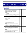
Chapter 14 – Status Registers ...................................................................................................................56
Table of S-Registers .............................................................................................................................56
Chapter 15 – Result Codes .........................................................................................................................58
Basic Result Codes ..............................................................................................................................58
Extended Cellular Result Codes ..........................................................................................................58
Extended Cellular Call Progress Result Codes ....................................................................................59
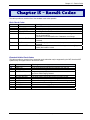
Chapter 16 – Stored Profile Settings .........................................................................................................60
Appendix A – Working With the IWF .........................................................................................................61
Introduction ..............................................................................................................................................61
Local and Remote Commands ................................................................................................................61
Local Only .............................................................................................................................................61
Shared ..................................................................................................................................................61
Remote-only .........................................................................................................................................62
Airlink Control ...........................................................................................................................................62
CDMA 1xEV-D0 AT Commands Reference Guide (Document S000482B)
5
Table of Contents
Establishing the Airlink .........................................................................................................................62
Initializing the Airlink .............................................................................................................................62
Pass through and Reflection ................................................................................................................63
Closing the Airlink .................................................................................................................................63
Modem Defaults and Configurations........................................................................................................63
Appendix B – ASCII Table ..........................................................................................................................64
Appendix C – Acronyms and Definitions..................................................................................................65
Index .............................................................................................................................................................66
CDMA 1xEV-D0 AT Commands Reference Guide (Document S000482B)
6
Chapter 1 – Introduction
Chapter 1 – Introduction
Document Structure
Following this introduction is a section on basic elements important to understanding and communicating with the
modem. This includes discussions of the QNC (Quick Net Connect) call setup process and interaction with the
CDMA Interworking Function (IWF), as well as notes on the connection between the host (DTE) and the Wireless
modem (DCE).
The document then presents the commands, registers, result codes, and defaults provided in the command state
of the modem.
Commands are often termed AT commands since this character sequence (originated by Hayes™) is used to
prefix each specific command.
In addition to the commands, the definitions and use of status registers are also described.
Commands are referenced in strict alphabetical order. This facilitates searches for the syntax, parameters, and
operation of specific commands. To help locate whether or not a command exists to perform a desired function,
tables organize the commands into these groups:
•
Basic modem operation actions – commands that make the modem execute an immediate action,
such as dialing, or restoring settings.
• Basic modem configuration – settings governing the modem’s behavior when executing basic
operations.
• Advanced modem configuration – settings governing the modem’s behavior related to advanced
operations (for example, Mobile IP).
• Account activation and management commands.
• Device and service interrogation commands – commands to determine the services available,
information about and the status of the modem.
• Voice operation – related to configuring, making, and controlling voice calls.
• SMS operations – commands to check, receive, and delete, incoming messages, and to originate
outgoing messages.
• GPS – commands (See Universal IP AT Commands Guide).
In addition to the commands, the definitions and use of status registers are also described. The factory / reset
defaults are listed in a separate table.
Result codes, both numeric and verbose, are provided in a separate table.
Extended Cellular Result Codes are also listed separately.
Conventions
The following format conventions are used in this reference.
Character codes or keystrokes that are described with words or standard abbreviations are shown within angle
brackets using a different font: such as <CR> for Carriage Return and <space> for a blank space character.
Numeric values are decimal unless prefixed as noted below.
Hexadecimal values are shown with a prefix of 0x, i.e. in the form 0x3D.
Binary values are shown with a prefix of 0b, i.e. in the form 0b00111101.
Command and register syntax is noted using an alternate font: !DSMS=<i>[,m].
The "AT" characters are not shown, but must be included before all commands except as noted in the reference
tables.
Characters that are required are shown in uppercase; parameters are noted in lowercase. Required parameters
are enclosed in angle brackets (<i>) while optional parameters are enclosed within square brackets ([m]). The
brackets are not to be included in the command string.
CDMA 1xEV-D0 AT Commands Reference Guide (Document S000482B)
7
Chapter 1 – Introduction
The default settings are noted in the command tables. Note that these are the factory default settings and not the
default parameter value assumed if no parameter is specified. The factory defaults are also noted in a section at
the end of each operational mode reference.
Result Code – This is a numeric or text code that is returned after all commands (except resets). Only one result
code is returned for a command line regardless of the number of individual commands contained on the line.
Response – This term indicates a response from the modem that is issued prior to a result code. Reading
registers or issuing commands that report information will provide a response followed by a result code unless
the command generates an error.
For a discussion of how the modem frames these two elements, see “Framing”.
Responses and result codes from the modem, or host system software prompts, are shown in this font:
CONNECT 14400
Modem Basics
CDMA Basics
To help understand the call connection process in CDMA modems, a basic knowledge of the CDMA network
helps. Two primary services are available using a CDMA 1xEVDO modem:
•
•
IS-95B, a circuit switched type of connection; and
1x/1xEVDO, a packet switched connection.
Traditional Wire Line
Before looking at the call setup process in CDMA, let's take a moment to review the traditional wire line
modem. A call is established by the local modem placing the call over the Public-Switched Telephone
Network (PSTN). The local and remote modems are connected and handshake the data protocol to use. The
local modem can monitor the call progress by picking up the dial tone, busy, ring, and answer from the PSTN
wire line connection.
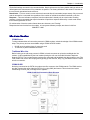
CDMA IS-95B
Not being connected to the PSTN, the modem must first connect to the CDMA network. The CDMA service
provider connects the call to either the PSTN or (by using QNC) the Internet. This environment uses an
Interworking Function (IWF) to bridge the two systems.
CDMA IS-95B Call Connection Block Diagram
CDMA 1xEV-D0 AT Commands Reference Guide (Document S000482B)
8
Chapter 1 – Introduction
When using IS 95, there is special handling of AT commands. For a detailed explanation, consult Appendix A
Where traditional wire line has only the local host and modem on one side, the CDMA IS-95 model requires
two modems on the local side: the IWF and the Wireless radio modem. These two modems must work as a
team to make a data connection.
For Internet connections, the interworking function can use a special feature called QNC (Quick Net
Connect). The IWF provides a link to the Internet without going through the PSTN.
Establishing a standard point-to-point call requires the cellular modem to configure a modem at the IWF. It is
the IWF modem that actually connects to the PSTN and dials the number. Call progress is not directly
available to the local modem, although some information can be exchanged. When the IWF has completed
the handshake with the remote modem, the local modem is advised and the connection is complete.
CDMA 1X
In areas where this service is provided, the modem can connect much like a local area network card. The
connection can be “always on” and only actively used when there is packet data to send or receive.
CDMA 1X offers higher speed data operations than are available with IS-95 service. IS 95 is limited to 14.4
kbps. The packet services of CDMA 1X use a fundamental channel at 9600 bps and can add supplemental
channels when needed to boost speed to as high as 153.6 kbps.
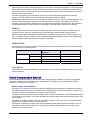
CDMA 1xEV-DO
In areas where this service is provided, the modem can provide packet data services at a much higher data
rate, as shown in the following table.
Data Service
1xEV-DO rev. 0
1xEV-DO rev. A
Upload
Download
Upload
Download
Theoretical Maximum
Data Rate
153 kbps
2.4 Mbps
1.8 Mbps
3.1 Mbps
Typical Data Rate
40–80 kbps
400–700 kbps
300–400 kbps
600–1300 kbps
Voice Service
Also added to the modem is the ability to make and receive voice calls. This allows the modem to serve as a
cellular telephone.
Host Connection Basics
The embedded modem provides a USB interface and optional serial port interfaces. To support the high data
rate of the 1xEVDO service the USB is highly recommended. The “Modem Port” presented is the interface
available for performing AT commands.
Modes, States, and Conditions
Discussion of the operation of the modem requires understanding the settings of the modem and just how it
is handling the data being sent to it. Describing the modem as being in a particular “mode” is not sufficient to
capture the various characteristics of the modem in any given case.
To improve clarity, this document uses the words “mode”, “state”, and “condition” to reflect different elements
of the modem’s configuration. This section describes the various modes, states, and conditions that are used
in the reference.
The CDMA 1X modems operate very much like a landline modem. There are, however, some differences in
that the modem supports multiple connection options.
One method of operation is to place a call just like a landline modem would (asynchronous serial). We call
this a CSC (Circuit Switched Cellular) call. This type of connection supports data communication, and is
available in IS-95 service areas.
CDMA 1xEV-D0 AT Commands Reference Guide (Document S000482B)
9
Chapter 1 – Introduction
An alternate (and more common) method is to place a QNC call by dialing a special number provided by
your carrier. QNC provides a mechanism to connect to the Internet using PPP, without using an intermediate
modem. This is functionally identical to using Dial-Up Networking for a PPP connection to an Internet Service
Provider (TCP/IP) on a standard landline modem. QNC offers a faster call connection time than standard
CSC calls. This is also available in IS-95 coverage.
EV-DO products introduce a third data connection type, using 1X service. This is a packet data connection
that does not tie up a circuit (or channel), but rather operates like a packet switched network, in which
multiple users share the resources and only use them when there is data to send or receive.
These three calling options are simply different methods of placing what amounts to a data call. As such they
are not included in the classification of modes, states, and conditions.
The commands and registers used depend on the modem’s operating mode. The state of the modem and its
condition also determine how the modem will behave in any given situation.
Modes
For the purposes of this document, the following are the modes of operation: Data and Voice.
Data (CSC, QNC, or Packet)
Connections to a PCS or cellular network for data transfers. This includes asynchronous (CSC) calls,
PPP packet connections to the network (QNC), and 1X packet service connections.
Voice
The product is being used for voice communication. In addition to the basic modes (data and voice),
there are states and conditions to consider.
States
The modem’s state, in conjunction with its condition, governs how the modem handles traffic to and from the
host (DTE), and to and from a remote modem. Data mode can support up to three states: Command, Pass
through, and Data.
Command
The modem exchanges data with the host (DTE) as AT commands and replies. This state handles
commands at the modem without the use of the airlink to the IWF modem. Voice modes are always
in command state.
Passthrough
The modem has an active airlink with the IWF but is otherwise in the Command state. Data from the
local host is passed through the modem to the IWF where it is executed as an AT command and
then reflected back for execution by the local modem. This state only applies to IS-95 calls, not 1X
packet connections.
Data
Communication is passed between the host and a remote terminal or network as computer data.
Note: Voice modes do not support the data state. Even while off hook with a voice call active,
the modem still communicates over the serial connection in command state. Commands can be
issued and executed while a voice call is in progress.
Conditions
In addition to mode and state the modem can be in one of two conditions: online and offline.
Online
Actively connected to a remote terminal or network (off-hook).
Offline
Disconnected from any remote terminal or network (on-hook).
While in offline condition the modem can only be:
• In command state (without an airlink), or
• In pass through state with an airlink to the IWF modem but without an active call.
CDMA 1xEV-D0 AT Commands Reference Guide (Document S000482B)
10
Chapter 1 – Introduction
In the online condition, the modem can be:
•
•
In data state, which passes data through the modem between the host (DTE) and the
remote terminal or network.
In pass through state (IS-95B), which exchanges commands and replies between the host
(DTE) and the IWF modem (DCE). The data is not sent all the way through the active
connection to the remote terminal. The remote connection is still active (carrier is
maintained) but data is not forwarded to the remote end.
State Transitions
On power up the modem is in command state.
Command to Data State
The modem changes to data state when a session is opened either by dialing a connection (or
answering a data or fax call). When a session opens, the modem issues the CONNECT message and
asserts the DCD control signal.
Note: Due to multi-processing in the modem, the DCD signal may be asserted slightly before the
modem has completed the transition to data state. The host device should allow a delay of 100
ms after receiving the complete CONNECT message and DCD signal before beginning
transmission; otherwise some data may be lost.
Data to Command State
When the modem changes to command state, an OK result is issued. This may be preceded by another
result (such as NO CARRIER) to indicate that the session was closed by an event outside the modem. A
closed session requires the modem to return to command state.
Several events can cause the modem to transition from data to command state based on mode.
SLIP mode transitions:
•
•
DTR is deasserted, with a configuration to use DTR (&D1 or &D2)
The modem receives the escape sequence as a SLIP frame:
(0xC0 +++ 0xC0)
• The modem is reset or power-cycled
PPP mode transitions:
•
•
•
DTR is deasserted, with a configuration to use DTR (&D1 or &D2)
PPP negotiates command state
The modem is reset or power-cycled
Modem Buffers
Communication with the modem is buffered to allow the modem to provide a variety of features and speed
configurations. This section provides an introduction to the types of buffering performed by the modem.
Command Buffer
When in command state, the modem buffers the input from the host until a <CR> is entered. The
buffered data can be edited using the backspace <BS>. The modem (with Echo enabled) may echo the
sequence <BS><space><BS> for human readability.
There is a limit of 518 characters to one command line, excluding the AT prefix and the <CR>
termination. If the command buffer length is exceeded, the modem continues to echo input (which is not
buffered) until the <CR> is received. When the <CR> is entered, the modem returns the ERROR result
code without executing any commands in the line. Once over the limit, the <BS> does not bring you back
under the limit; the ERROR code is still returned.
The command buffer is distinct from the data receive and transmit buffers. The command buffer retains
the contents of the last issued command until the AT command prefix is received for the next command.
CDMA 1xEV-D0 AT Commands Reference Guide (Document S000482B)
11
Chapter 1 – Introduction
Data Buffers
Data being transmitted or received is buffered in several ways depending on the mode and nature of the
connection. Some caution must be taken when disconnecting to ensure that any buffered data in the
modem has been properly processed prior to breaking the connection.
Specific settings for buffer controls are described in the relevant commands and registers. Normal
configuration of the modem does not require you to adjust these settings.
Speed Buffering
The simplest form of buffering allows for line speed differences and busy conditions between the host
(DTE) and modem and between the modem and the remote terminal or network. The network side of the
connection can have rates up 153.6 kbps, while the local host connection can be at one of many different
speeds from 300 bps to 230.4 kbps.
Where large amounts of data are being exchanged, local hardware flow control must be used to prevent
buffer overflows. To reduce packet loss, the CDMA protocol incorporates flow control on the network
connection.
Command Handling
AT can be issued as a command without parameters. It acts like a “ping” to the modem and always gives a result
code of “OK”. If there is no response from the modem, try issuing ATQ0 (Quiet mode off). If this fails, try the
“+++” escape sequence or resetting the modem.
Commands may be entered in upper or lower case.
Concatenation
More than one command can be included in a single line, although some commands or their parameters
must be placed at the end of the line. When concatenating commands, a space between basic
commands is optional. Where extended commands (those beginning with a non-alphabetic character)
are concatenated, they must be separated by a semi-colon.
Commands are executed in the order entered. If a command results in the ERROR result code, the
balance of the command line is ignored. Only one result code is returned for the entire command line.
Parameters
Most AT commands support one or more parameters, usually a number. Parameter ranges are specified
in the reference.
Commands that normally accept a single numeric option switch ([n]) and are issued without that
parameter assume a value of zero (0).
Defaults shown in the command tables are those for the factory settings of the modem and are not the
defaults assumed for a command issued without parameters.
Registers
Some registers are read only. If an attempt is made to write to a read only register, the ERROR result
code is returned.
Some registers store the setting of commands. Changing the register is equivalent to changing the
command setting. See the Table of S-Registers for the standard default values.
See the Table of Stored Profile Settings for the factory defaults.
CDMA 1xEV-D0 AT Commands Reference Guide (Document S000482B)
12
Chapter 1 – Introduction
Responses and Result Codes
Most commands return only a result code however some commands request information, which is provided by
the modem as a response prior to the result code.
Possible Result Codes
Result codes are not shown in the command tables unless special conditions apply. Generally the result
code OK is returned when the command has been executed. ERROR may be returned if parameters are
out of range, and is returned if the command is not recognized, or the command is not permitted in the
current mode, state, or condition of the modem.
See the Table of Result Codes, giving both the numeric and verbose results.
Human vs. Machine Interface
The AT command interface was designed for human interaction. When an intelligent host is managing a
modem, the interface may need to be altered; result code words replaced with numbers, for example.
Framing characters (line feeds and carriage returns) must be properly understood to ensure the host
system properly parses the responses and result codes.
As shipped the modem is configured with these settings:
•
Echo enabled (E1): which causes the modem to echo characters received from the host back to
it while in command state. The backspace is echoed as <BS>.
• Quiet result codes disabled (Q0): which enables the modem to issue result codes following
commands. Quiet on (Q1) suppresses result codes entirely; responses remain unaffected.
• Verbose result codes (V1): which provides results in English text appended with <CR><LF>.
Verbose off (V0) returns the results as ASCII numeral codes. Numeric codes are much easier to
process.
With Echo on (E1 - the default), data received from the local host while in command state is echoed back
to the host. This can present problems to machine control, which is not interested in an echo of its own
commands to the modem. In some configurations the echo should be turned off (E0).
The configuration for most machine-controlled hosts is more likely to be set to Echo Off, and Verbose Off
or possibly Quiet On.
Framing
The framing of the response and result elements by <CR><LF> depends heavily on the settings of the
modem. In particular the settings of Verbose (V) and Quiet (Q) modes alter the framing of both
responses and result codes.
These elements are normally formatted for human reading with a terminal program, however users
wishing to have software read and adjust to these responses and result codes must understand how
they are framed.
Framing Characters
The modem will frame replies with carriage return and line feed characters as they are defined in
registers S3 and S4 respectively. These are normally the ASCII values 13 <CR> and 10 <LF>.
For the purposes of the discussion here, they are referred to as <CR> and <LF>.
If there are any problems determining the exact framing of the response and result codes, use a
protocol analyzer to monitor the exchanges.
Response Framing
Regardless of command settings, responses are in ASCII text with a trailing <CR><LF>. Where a
response has more than one line, each line is terminated with a <CR><LF>. The programmer must know
the number of lines expected in the response.
The setting of Verbose (V) on (=1) triggers a leading <CR><LF> prior to the first line of the response. If
Verbose is off (=0), there are no leading characters prior to the first line of response.
The setting of Quiet (Q) has no impact on responses.
CDMA 1xEV-D0 AT Commands Reference Guide (Document S000482B)
13
Chapter 1 – Introduction
Result Code Framing
Every command returns a result code unless the Quiet command is enabled. If Quiet (Q) is on (=1), then
there are no framing characters nor any result code returned; the modem is truly silent with respect to
result codes.
A leading <CR><LF> is inserted ahead of the result code if Verbose (V) is on (=1), otherwise there are
no leading characters prior to the ASCII numeral result.
The result code is always followed by a <CR>. There is a trailing <LF> only if Verbose is on. Samples:
V=1 <CR><LF>OK<CR><LF>
V=0 0<CR>
CDMA 1xEV-D0 AT Commands Reference Guide (Document S000482B)
14
Chapter 2 – Overview of Commands
Chapter 2 – Overview of
Commands
Introduction
The modem supports commands for:
• IS 95B data service
• 1X packet service
• SMS
• GPS (See Universal IP AT Commands Guide)
AT Commands Summary by Function
The reference tables are presented in strict ASCII alphabetical order (including prefixes). This format allows
quick look-up of each command to verify syntax, parameters, and behaviors. It does not lend itself to finding
whether or not the modem has a command to perform a particular service or setting.
The summary in this section organizes the commands into functional groups to allow you to more quickly locate a
desired command when the operation is known but the command is not.
Basic Operation Action Commands
Command
&F
&V
+++
A
D
H
O
Z
-DTMFB
-DTMFK
-RESET
-SHTDWN
-TONMUT
Description
Factory Settings Restore
View Configuration
Escape from Data State to Command State
Answer – Manual
Dial
Hook Control
Online (Remote)
Profile Restore
DTMF Burst
DTMF Key
Reset
Shutdown
Tone Mute
Basic Modem Configuration Commands
Command
&C
&D
+CFG
+CMUX
+CQD
+CRC
+CRM
+CTA
+CXT
+FCLASS
Description
Data Carrier Detect Control
Data Terminal Ready Options
Configuration String
Multiplex Option
Command State Inactivity Timer
Cellular Result Codes
Local (Rm) Interface Protocol
Packet Data Inactivity Timer
Cellular Extension
Modem Operating State
CDMA 1xEV-D0 AT Commands Reference Guide (Document S000482B)
15
Chapter 2 – Overview of Commands
Command
+ICF
+ILRR
+IPR
+MA
+MR
+MS
+MV18R
+MV18S
+WWKUP
E
L
M
P
Q
S
T
V
X
-HDSET
-TONDUR
Description
Character Framing
Local Rate Reporting
Fixed Port (Rm) Rate
Modulation Auto mode
Modulation Reporting
Modulation Selection
V.18 Reporting
V.18 Selection
Wake-up Events Mask
Echo (Command State)
Loudness (Speaker Volume)
Mute (Speaker Control)
Pulse Dialing
Quiet – Result Code Display Option
S-Register Read and Write
Tone Dialing
Verbose – Result Code Form
Result Code/Call Progress Control
Headset Detection Option
Tone Duration
Advanced Modem Configuration Commands
Command
!APPSUBTYPES
!MUFWDRESET
!MUFWDSTATS
!PERSONALITY
!PROTSUBTYPES
!SCPCUSTCONFIG
!SESSIONSTATUS
!SIPID
!SIPPWD
!SLEEPPARMS
!SUFWDCCSTATS
!SUFWDCRCS
!SUFWDRESET
!SUFWDTCSTATS
$QCMIP
$QCMIPEP
$QCMIPGETP
$QCMIPNAI
$QCMIPP
Description
Application subtypes negotiated for the four streams
Resets all the data reported by !MUFWDSTATS.
Current Multi-User Forward Traffic Channel Statistics
Current personality and its negotiated protocol subtypes
Negotiated subtypes for all protocols in all stored personalities
Current Session Configuration Protocol Customer configuration
Current HDR session status
Simple IP setup (user ID)
Simple IP setup (password)
1xEV-DO Rev. A sleep parameters (slot cycle indexes and sleep periods)
Current Single User Forward Channel Statistics (Single User packet early
slot termination count for all supported DRCs on Forward Control Channel)
Current Single User Forward Channel Statistics (Single User packet CRCs
and Packet Error Rate).
Resets the data reported by !SUFWDCCSTATS, !SUFWDCRCS, and
!SUFWDTCSTATS.
Current Single User Forward Channel Statistics (Single User packet early
slot termination count for all supported DRCs on Forward Traffic Channel)
Mobile IP behavior
Enables/disables the currently active Mobile IP user profile.
Query a user profile
Set the Network Access ID (NAI) for the currently active profile
Select one of the Mobile IP user profiles to be the current active profile
CDMA 1xEV-D0 AT Commands Reference Guide (Document S000482B)
16
Chapter 2 – Overview of Commands
Account Activation Commands
The modem supports modem account activation via the AT command interface.
Command
Description
-NAMLCK
NAM Lock—enter the subsidy lock or SPC required to write account data
-NAMVAL
NAM Values—query or set the account data
Device and Service Interrogation Commands
Command
I
!ECIO
!GMODE
!MDMVER
!PREV
!PRLVER
!RSSI
!STATUS
!SYSTIME
+CAD?
+CBIP?
+CMIP
+CSQ
+CSS?
+GCAP
+GMI
+GMM
+GMR
+GOI
+GSN
+WGETWK
Description
Product identification information
Ec/Io
Mode of the modem
Version of the modem firmware
Protocol Revision
PRL version
Received Signal Strength Indication
Modem status report
CDMA time
Analog or Digital Service (Read-only) (local only)
Base Station IP Address (Read-only)
Mobile Station IP Address (Read-only)
Signal Quality (Read-only)
Serving System (Read-only)
Get Capabilities
Get Manufacturer
Get Model Number
Get Revision
Get ISO ID
Get ESN
Request Wake-up Reason
SMS Messages Commands
The modem supports sending and receiving SMS (Short Message Service) messages.
Command
Description
!CNTSMS
Count of SMS messages in the modem
!DASMS
Delete All SMS messages
!DSMS
Delete SMS message (selective)
!GSMS
Get SMS message from the modem
!SSMS
Send SMS message, or query the send status
CDMA 1xEV-D0 AT Commands Reference Guide (Document S000482B)
17
Chapter 3 – ! Prefix Commands
Chapter 3 – ! Prefix Commands
Result codes are not shown in the following commands unless special conditions apply. Generally, the result
code OK is returned when the command has been executed. ERROR may be returned if parameters are out of
range and is returned if the command is not recognized or is not permitted in the current state or condition of the
modem. A full list of result codes (verbose and numeric) is provided in the Result Code Table later in this manual.
!APPSUBTYPES Negotiated Subtypes
Syntax:
AT!APPSUBTYPES
Description: Application subtypes negotiated for the four streams.
Example:
AT!APPSUBTYPES
Stream0: Default Signaling Application
Stream1: Default Packet Application for SN
Stream2: Default Packet Application for AN
Stream3: Default Test Application
OK
!CNTSMS Count SMS
Syntax:
AT!CNTSMS
Description: Reports the number of messages stored in the modem as follows:
New Urgent Msg
{Index = 1}: <n>
New Regular Msg {Index = 2}: <r>
Old Messages
{Index = 3}: <o>
Voice Messages
{Index = 4}: <v>
The Index number corresponds to the SMS list index used to retrieve and delete
messages. The counters n, r, o, and v indicate the number of messages in each list.
When retrieving (!GSMS) or deleting (!DSMS), the message number is base 1, so the
highest message number in any list is the same as the reported count.
!DASMS Delete All SMS
Syntax:
AT!DASMS
Description: Deletes all SMS messages from all four SMS lists. Use this command with care, as
confirmation is not required.
CDMA 1xEV-D0 AT Commands Reference Guide (Document S000482B)
18
Chapter 3 – ! Prefix Commands
!DSMS= Delete SMS (Selective)
Syntax:
!DSMS=<i>[,m]
Description: Deletes one or all messages from one of the index lists (for the definitions of the SMS
index lists, see !CNTSMS).
Parm
Meaning
i
Message list (index 1, 2, 3, or 4)
m
Message number
Message number 1 is the oldest message, and the number reported by !CNTSMS, is the
most recent message.
If the message number parameter is omitted, then all messages in the specified index list
are deleted.
Normally messages are only deleted from list 3 (old).
!ECIO? Ec/Io
Syntax:
AT!ECIO?
Description: If there is an active pilot, returns the current Ec/Io in units of 1dB. See also !RSSI.
!GMODE Mode of the Modem
Syntax:
AT!GMODE
Description: Asks for the mode of the modem. Returns either “ONLINE” or “OFFLINE”
!GSMS? Get SMS
Syntax:
AT!GSMS?<i,m>
Description: Read an SMS message from the modem. The message read is determined by the
parameters:
Parm
Meaning
i
message list (index 1, 2, or 3)
m
message number
Message number 1 is the oldest message, and the number reported by !CNTSMS, is the
most recent message.
After a new message is read, it is placed in message list index 3 (old messages).
The following information may be displayed:
• Message center timestamp (optional)
• Originating address
• Priority (optional)
• User data
!MDMVER? Version of the Modem Firmware
Syntax:
AT!MDMVER?
Description: Returns the firmware version being run on the modem.
See also +GMR (Get Revision).
CDMA 1xEV-D0 AT Commands Reference Guide (Document S000482B)
19
Chapter 3 – ! Prefix Commands
!MUFWDRESET Reset Data in !MUFWDSTATS
Syntax:
AT!MUFWDRESET
Description: Resets all the data reported by !MUFWDSTATS.
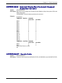
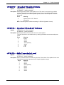
!MUFWDSTATS Current Traffic Channel Statistics
Syntax:
AT!MUFWDSTATS
Description: Current Multi-User Forward Traffic Channel Statistics.
!MUFWDRESET resets the data reported by this command.
Example:
at!mufwdstats
FORWARD TRAFFIC CHANNEL
CRC Count
--------Good CRCs----Bad CRCs
DRC3_128 0
DRC3_256 0
DRC3_512 0
DRC3_1024 0
0
DRC5_2048 0
0
DRC8_3072 0
0
DRC10_4096 0
0
DRC13_5120 0
0
Packet Error Rate (%): 0.000
OK
Termination Slot Count
1 2 3 4
0 0 0 0
0 0 0 0
0 0 0 0
0 0 0 0
0 0 0 0
0 0
0 0
0 0
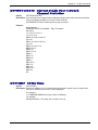
!PERSONALITY? Displays Current Personality
Syntax:
AT!PERSONALITY?
Description: Displays the Current Personality and its negotiated protocol subtypes.
Example:
at!personality?
Current Personality: 0
Physical Layer Protocol Subtype: 0
Control Channel MAC Protocol Subtype: 0
Access Channel MAC Protocol Subtype: 0
Fwd Traffic Channel MAC Protocol Subtype: 0
Rev Traffic Channel MAC Protocol Subtype: 0
Key Exchange Protocol Subtype: 0
Authentication Protocol Subtype: 0
Encryption Protocol Subtype: 0
Security Protocol Subtype: 0
Idle State Protocol Subtype: 0
Generic MM Cap Disc Protocol Subtype: 0
Generic Virtual Stream Protocol Subtype: 0
OK
CDMA 1xEV-D0 AT Commands Reference Guide (Document S000482B)
20
Chapter 3 – ! Prefix Commands
!PREV? Protocol Revision
Syntax:
AT!PREV?
Description: Queries the modem for the current protocol revision reported by the current base station
the modem is communicating with. The response is a decimal digit as noted below.
Value
Meaning
1
JSTD-008 (PCS)
2
IS-95
3
IS-95A (cellular)
4
Minimum requirements for IS-95B
5
Full requirements for IS-95B
6
CDMA 1X Rev. 0
7
CDMA 1X Rev. 1
!PRLVER? PRL Version
Syntax:
AT!PRLVER?
Description: Returns the version of the PRL stored in the modem.
!PROTSUBTYPES? Negotiated Subtypes
Syntax:
AT!PROTSUBTYPES?
Description: Displays Negotiated Subtypes for all protocols in all stored personalities.
Example:
at!protsubtypes
Number of Stored Personalities: 1
Current Personality: 0
Personality: 0
Physical Layer Protocol Subtype: 0
Control Channel MAC Protocol Subtype: 0
Access Channel MAC Protocol Subtype: 0
Fwd Traffic Channel MAC Protocol Subtype: 0
Rev Traffic Channel MAC Protocol Subtype: 0
Key Exchange Protocol Subtype: 0
Authentication Protocol Subtype: 0
Encryption Protocol Subtype: 0
Security Protocol Subtype: 0
Idle State Protocol Subtype: 0
Generic MM Cap Disc Protocol Subtype: 0
Generic Virtual Stream Protocol Subtype: 0
OK
CDMA 1xEV-D0 AT Commands Reference Guide (Document S000482B)
21
Chapter 3 – ! Prefix Commands
!RSSI? Received Signal Strength Indication
Syntax:
AT!RSSI?
Description: Reports the current RSSI (P(AGC)+Ec/Io) in dBm using a (N-1)/N IIR filter for smoother
display. When no signal is present it reports -125. Reported values can be interpreted as
follows:
< -90 = very poor
-90 to -86 = poor
-85 to -81 = fair
-80 to -76 = good
> -76 = excellent
This command is supported in the online command state and in the command state.
!SCPCUSTCONFIG? Current Session Configuration
Protocol Customer Configuration
Syntax:
AT!SCPCUSTCONFIG?
Description: Sets or reads the current Session Configuration Protocol Customer configuration.
Example:
at!scpcustconfig?
1 - Custom Configuration is Active
Protocol Subtypes:
1 - Subtype 2 Physical Layer
0 - Enhanced CCMAC
1 - Enhanced ACMAC
1 - Enhanced FTCMAC
0 - Enhanced 3 RTCMAC
0 - Enhanced 1 RTCMAC
0 - Enhanced Idle
Broadcast Subtypes:
0 - Generic Broadcast Enabled
Applications Subtypes:
1 - SN Multiflow Packet App
OK
To set this item, enter 13 hex bytes. Example:
at!scpcustconfig=01,0D,00,00,00,00,00,00,00,01,00,00,00
OK
CDMA 1xEV-D0 AT Commands Reference Guide (Document S000482B)
22
Chapter 3 – ! Prefix Commands
!SESSIONSTATUS Current Session Status
Syntax:
AT!SESSIONSTATUS=<lower_byte>,<upper_byte>
Description: !SESSIONSTATUS (Sets the current Session Status)
!SESSIONSTATUS? (Reads the current Session Status)
Value
Meaning
0
Inactive—there is no session
1
Default—there is a session, but no negotiation has been completed
2
Active—there is a session, and all parameters have had at least one chance
to be negotiated
In testing and debugging procedures, it is useful to force the session status to Inactive, so
that Session negotiation and configuration occur upon the next power up. For the change
to occur, the modem must be reset.
When the HDR session is negotiated, the session status is stored in NV RAM. Upon next
power up, if the session status is Active, the session parameters are not renegotiated,
unless a new network is acquired.
Example:
at!sessionstatus
HDR Session Status: 2
OK
at!sessionstatus=00,00
OK
at!sessionstatus?
HDR Session Status: 0
OK
!SIPID= User ID Information for Simple IP Setup
Syntax:
AT!SIPID=<user id>
Description: Sets the User ID information for a simple IP setup.
!SIPPWD= Password Information for Simple IP Setup
Syntax:
AT!SIPPWD=<passwrd>
Description: Sets the password information for a simple IP setup.
CDMA 1xEV-D0 AT Commands Reference Guide (Document S000482B)
23
Chapter 3 – ! Prefix Commands
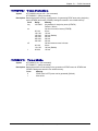
!SLEEPPARMS Sleep Parameters
Syntax:
AT!SLEEPPARMS
Description: Returns 1xEV-DO Rev. A sleep parameters (slot cycle indexes and sleep periods). Slot
cycle timeouts are listed in Julian time format (year month day day-of-week
hour:minutes:seconds).
Example 1:
at!sleepparms
Slot Cycle1:3
Slot Cycle2:0
Slot Cycle3:0
Slot Cycle1 Timeout:1980 01 06 6 00:00:00
Slot Cycle2 Timeout:1980 01 06 6 00:00:00
OK
Example 2:
at!sleepparms
HDR Rev. A not currently available
OK
!SSMS= Send SMS
Syntax:
AT!SSMS=<p>,<dest>,[cb],”<text>”
AT!SSMS? Reports the progress of the last message sent
Description: !SSMS= sends an SMS message using these parameters:
Parm
Meaning
Range
p
priority
0 = normal
1 = interactive
2 = urgent
3 = emergency
(Actual priority transmitted depends on the carrier.)
dest
destination #
Phone number of destination, maximum of 32 characters; only
0–9, #, and * permitted.
cb
callback #
(this is optional) Phone number for reply, same 32 character
limit
text
message body
Up to 227 bytes of data (not including the compulsory quote
marks).
The text is enclosed in quotations. The quote character cannot appear in the body text.
Body text over the carrier-defined limit is truncated and sent anyway. Messages of length
228 or greater result in an ERROR.
The query form (!SSMS?) reports the progress of the last message sent.
Possible responses are:
none
No SMS messages being sent.
pending Message has not left the modem (an attempt to use !SSMS= again yields
an ERROR result code.)
sent
Successfully sent to the network.
failed
Sending failed and should be retried.
If you send a second message after receiving the "sent" response for the first message,
subsequent queries will report the status of the second message.
CDMA 1xEV-D0 AT Commands Reference Guide (Document S000482B)
24
Chapter 3 – ! Prefix Commands
!STATUS Status of the Modem
Syntax:
AT!STATUS
Description: Reports the modem’s status as follows:
Current band: <band>
Current channel: <chan>
SID: <sid> NID: <nid> 1xRoam: <n>
HDRRoam: <n>
Temp: <temp> State: <state> Sys Mode:<mode>
Pilot [NOT] acquired
Modem has [NOT] registered
HDR revision: <HRD_rev>
<band> is either OFFLINE, PCS CDMA, Cellular CDMA, PCS Sleep, Cellular Sleep, HDR
PCS, or HDR Cellular
<n> for the roaming indicator. Values larger than 2 indicate ERI usage; to obtain the ERI
banner, icon state, and icon image, parse the carrier’s ERI file.
<temp> is the radio temperature in degrees C.
<mode> is either NO SRV, CDMA or HDR
NOT appears if the pilot has not been found or the modem has not registered.
<HRD_rev> is displayed only if the modem has 1xEV-DO service.
The value is either 0 or A. See also +CSS? (Serving System).
!SUFWDCCSTATS Current Single User Forward
Channel Statistics on DRCs
Syntax:
AT!SUFWDCCSTATS
Description: Reports the current Single User Forward Channel Statistics (Single User packet early slot
termination count for all supported DRCs on Forward Control Channel; (columns are tab
separated).
!SUFWDRESET resets the data reported by this command.
Example:
at!sufwdccstats
FORWARD CONTROL CHANNEL - Early Termination
Slot Count
1 2 3 4 5 6 7 8 9 10 11 12
13 14 15 16
DRC0 0 0 0 0 0 0 0 0 0 0 0 0
0000
DRC1 0 0 0 0 0 0 0 0
OK
CDMA 1xEV-D0 AT Commands Reference Guide (Document S000482B)
25
Chapter 3 – ! Prefix Commands
!SUFWDCRCS Current Single User Forward Channel
Statistics on CRCs
Syntax:
AT!SUFWDCRCS
Description: Reports the current Single User Forward Channel Statistics (Single User packet CRCs and
Packet Error Rate).
!SUFWDRESET resets the data reported by this command.
Example:
at!sufwdcrcs
FORWARD TRAFFIC CHANNEL
Good CRCs
Bad CRCs
DRC0
0
0
DRC1
0
0
DRC2
0
0
DRC3
0
0
DRC4
0
0
DRC5
0
0
DRC6
0
0
DRC7
0
0
DRC8
0
0
DRC9
0
0
DRC10
0
0
DRC11
0
0
DRC12
0
0
DRC13
0
0
DRC14
0
0
FORWARD CONTROL CHANNEL
Good CRCs
Bad CRCs
DRC0
0
0
DRC1
0
0
Packet Error Rate (%): 0.000
OK
!SUFWDRESET Resets Data
Syntax:
AT!SUFWDRESET
Description: Resets the data reported by !SUFWDCCSTATS, !SUFWDCRCS, and !SUFWDTCSTATS.
CDMA 1xEV-D0 AT Commands Reference Guide (Document S000482B)
26
Chapter 3 – ! Prefix Commands
!SUFWDTCSTATS Current Single User Forward
Channel Statistics
Syntax:
AT!SUFWDTCSTATS
Description: Current Single User Forward Channel Statistics (Single User packet early slot termination
count for all supported DRCs on Forward Traffic Channel).
!SUFWDRESET resets the data reported by this command.
Example:
at!sufwdtcstats
FORWARD TRAFFIC CHANNEL - Early Termination
Slot Count
1 2 3 4 5 6 7 8 9 10 11
12 13 14 15 16
DRC0 0 0 0 0 0 0 0 0 0 0 0
00000
DRC1 0 0 0 0 0 0 0 0 0 0 0
00000
DRC2 0 0 0 0 0 0 0 0
DRC3 0 0 0 0
DRC4 0 0
DRC5 0 0 0 0
DRC6 0
DRC7 0 0
DRC8 0 0
DRC9 0
DRC10 0 0
DRC11 0
DRC12 0
DRC13 0 0
DRC14 0
OK
!SYSTIME? CDMA Time
Syntax:
AT!SYSTIME?
Description: Queries the CDMA time. If the modem has not acquired a system, then the system time
may not be available; some time in 1980 is displayed.
The format is:
YYYYMMDDWHHMMSS (W is day of week, 0=Monday)
For example:
200309183180142 = Thursday, Sep 18, 2003, 18:01:42
CDMA 1xEV-D0 AT Commands Reference Guide (Document S000482B)
27
Chapter 4 – $ Prefix Commands
Chapter 4 – $ Prefix
Commands
$QCCAV Answer Voice
Syntax:
AT$QCCAV
Description: (Voice builds only). Answers an incoming call as a voice call. Use –SPKMUT (Speaker
Mute) to manually turn off mute on the audio path before answering the call.
Contrast with A (Answer).
See also +CDV (Dial Voice) and +CHV (Hang-up Voice).
$QCMIP
Mobile IP (MIP) Behavior
Syntax:
AT$QCMIP
Description: Sets the Mobile IP (MIP) behavior.
Value
Meaning
0
Mobile IP disabled. Simple IP only.
Mobile IP preferred.
1
In the initial MIP registration, if the network does not support Mobile IP, then the
mobile automatically reverts to Simple IP. However, if a Mobile IP session is
registered and then the mobile enters a network that does not support Mobile IP,
the mobile will drop the session and inform the upper layers of the failure.
2
Mobile IP only.
The mobile will make data calls only when Mobile IP is supported in the network.
During a MIP session, if the mobile hands off to a network that does not support
MIP, then the mobile will drop the session and inform the upper layers of the
failure.
If a connected data device wants to use its own Mobile IP implementation, the mobile’s IP
implementation should be disabled by setting AT$QCMIP to 0.
$QCMIPEP Enables/Disables the Currently Active
Mobile IP User Profile
Syntax:
AT$QCMIPEP
Description: Enables/Disables the currently active Mobile IP user profile.
Value
Meaning
0
To disable the currently active profile, use AT$QCMIPEP = 0.
1
To enable the currently active profile, use AT$QCMIPEP = 1.
See also $QCMIPP.
CDMA 1xEV-D0 AT Commands Reference Guide (Document S000482B)
28
Chapter 4 – $ Prefix Commands
$QCMIPGETP Query a User Profile
Syntax:
AT$QCDMIPGETP
Description: $QCDMIPGETP = 1-5 (profile number).The command returns the following parameters for
the selected profile:
• NAI
• Home Addr
• Primary HA
• Secondary HA
• MN-AAA SPI
• MN-HA SPI
• Rev Tun (Reverse Tunneling)
• MN-AAA SS
• MN-HA SS
If a profile number is not entered, then the AT command returns all the information
corresponding to the currently active profile.
$QCMIPNAI Set the Network Access ID (NAI) for the
Currently Active Profile
Syntax:
AT$QCMIPNAI
Description: Sets the Network Access ID (NAI) for the Currently Active Profile:
AT$QCMIPNAI= "user@domain", 0 or 1
Value
Meaning
0
Do not store in NOVRAM
1
Store in NOVRAM
The double quotes (“ ”) are required only if the string contains a comma.
$QCMIPP Select One of the Mobile IP User Profiles to
Be the Current Active Profile
Syntax:
AT$QCMIPP
Description: AT$QCMIPP can be used to configure specific dial-up for various user profiles.
AT$QCMIPP = 1-5 (profile number)
To enable/disable a currently active profile, see $QCMIPEP.
CDMA 1xEV-D0 AT Commands Reference Guide (Document S000482B)
29
Chapter 4 – $ Prefix Commands
$QCVAD= Sets or Reads the Mode for Answering Data
Calls
Syntax:
AT$QCVAD=<n> (Set Command)
AT$QCVAD? (Read Command)
Description: $QCVAD= sets the mode for answering data calls with A (Answer) or auto answer via
S0=1.
$QCVAD? reads the mode for answering data calls with A (Answer) or auto answer via
S0=1.
Value
Setting
0
OFF (answer as voice). Default.
1
Fax (Fax not supported) for next call, then revert to OFF (voice)*
2
Fax (Fax not supported )for all calls
3
Async data for next call, then revert to OFF (voice)*
4
Async data for all calls
*Reverting to voice happens at the first of these events:
• An incoming call arrives (answered or not)
• Ten minutes elapse without receiving a call
• The modem is reset (or power-cycled)
• The setting is changed by command
The CDMA network requires the call type to be negotiated before the call is answered.
This command sets the call negotiation the modem makes prior to answering.
CDMA 1xEV-D0 AT Commands Reference Guide (Document S000482B)
30
Chapter 5 – & Prefix Commands
Chapter 5 – & Prefix
Commands
&C Data Carrier Detect Control
Syntax:
AT&C<value>
Description: The modem controls the RLSD output in accordance with the parameter supplied. This
command sets the DCD On or Off.
Value
Setting
0
Sets DCD to remain On at all times.
1
Sets DCD to follow the physical connection. Default
2
DCD follows the state of the TCP/UDP connection.
Response:
OK
Otherwise ERROR
&D Data Terminal Ready Options
Syntax:
AT&D[n]>
Description: Determines what actions the modem takes in response to the Data Terminal Ready (DTR)
signal from the host (DTE). For action to be taken, DTR must be off for a period of 2–10
milliseconds.
Note:
Value
0
1
2
This command has no impact on the use of DTR to terminate a voice call on the
modem, nor does it affect the use of DTR to control modem shutdown.
Setting
Ignore DTR
Enter command state for an on-to-off DTR transition.
The modem condition (on or offline) is not affected.
(Currently not supported.)
Hang up and enter command state for an on-to-off DTR transition. Autoanswer is disabled if DTR is off. Default.
&F Factory Settings Restore
Syntax:
AT&F
Description: Reloads the factory-stored default configurations into active memory. For information on
factory settings, see the Stored Profile Settings Table later in this manual.
This command is functionally the same as Z (Reset). If there is an active call, the
command executes and the call is dropped.
&V View Configuration
Syntax:
AT&V[n]
Description: Displays the active profile (commands and S-register contents).
Any numeric parameter is ignored.
CDMA 1xEV-D0 AT Commands Reference Guide (Document S000482B)
31
Chapter 6 – +C Prefix Commands
Chapter 6 – +C Prefix
Commands
+CAD? Analog or Digital Service
Syntax:
AT+CAD? (Read-only) (local only)
Description: Reports the current service mode of the modem in the form +CAD: n.
Value
Meaning
0
No service available
1
CDMA Digital service is available
2
TDMA Digital service is available
3
Analog service is available
+CBIP? Base Station IP Address (Read-only)
Syntax:
AT+CBIP? (Read-only) (local only)
Description: Reports the IP address (in dotted-decimal format) of the Base Station if there is a currently
active call. If there is no active call, the following response is returned:
0.0.0.0
OK
See also +CMIP (Mobile IP Address).
+CDV Dial Voice
Syntax:
AT+CDV [options]
Description: Initiates a voice call. Because of the options available in this command, another AT
command cannot follow it on the same line. All characters following the +CDV command
are taken as parameter options. For a list of dialing option parameters and restrictions, see
the D (Dial) command. The options available are the same as those described for async
data dialing.
Voice dialing leaves the modem in command state. This allows use of commands to
control microphone and speaker options, and to generate DTMF tones if needed.
See also +CHV (Hang-up Voice).
Note: This command is needed for Verizon
CDMA 1xEV-D0 AT Commands Reference Guide (Document S000482B)
32
Chapter 6 – +C Prefix Commands
+CFG= Configuration String
Syntax:
AT+CFG=”<str>” (Sets a configuration)
AT+CFG? (Reads a configuration)
Description: This command sets a configuration string of up to 248 characters. The string parameter
must be enclosed within quotation marks (0x22). You cannot append any other commands
after it in the same command line.
This string is transmitted to the Base Station as the last step of establishing the transport
layer of the airlink. The default setting is null. Any setting replaces the previous value.
+CHV Hang-up Voice
Syntax:
AT+CHV [0]
Description: Terminates a voice connection previously established with +CDV (Dial Voice) or $QCCAV
(Answer Voice). The only valid parameter is zero, which is optional.
See also H (Hook Control).
+CMIP? Mobile Station IP Address
Syntax:
AT+CMIP? (Read only)
Description: Returns the IP address assigned to the modem for this connection. This address is
temporary only. The network assigns an IP address on an as-needed basis.
If there is no current network connection, hence no local IP address, the modem issues no
response, only the OK result code.
See also +CBIP (Base Station IP Address).
+CMUX= Multiplex Option
Syntax:
AT+CMUX=<f[,r]> (Sets the Multiplex Option)
AT+CMUX? (Reads the Multiplex Option)
Description: Selects the maximum number of multiplex options for the forward and reverse links valid
within the context of the data service selected by the +CRM (Local Interface Protocol)
command. The first parameter is for the forward link (from the Base Station to the modem)
and the second is for the reverse link (from the modem to the Base Station).
Parm
Value
Meaning
f
1-F
Hexadecimal value for Multiplex Option for the forward link.
r
1-2
Multiplex Option for the reverse link.
If parameter r is omitted, it is assumed to have the same value as f, provided f is 1 or 2;
otherwise, the ERROR result is returned.
Values for the two parameters must be either both odd or both even. If odd values are
used, the modem originates data calls using Rate Set 1. If both are even, originated calls
use Rate Set 2.
Note: This command is included for compatibility.
CDMA 1xEV-D0 AT Commands Reference Guide (Document S000482B)
33
Chapter 6 – +C Prefix Commands
+CQD= Command State Inactivity Timer
Syntax:
AT+CQD=<n> (Sets the Command State Inactivity Timer)
AT+ CQD? (Reads the Command State Inactivity Timer)
Description: This timer determines when (or if) the modem will release a call if there is no activity on the
connection between the modem and the IWF, for the specified period. The entry
represents a multiple of five seconds. That is, each unit represents 5 seconds.
Value
Meaning
0
Disables the timer
1–255
Indicates timer value in steps of five seconds.
The default value is 10 – meaning a timer setting of 50 seconds.
See also +CTA (Packet mode Inactivity Timer).
Note: This command is included for compatibility.
+CRC= Cellular Result Codes
Syntax:
AT+CRC=<n> (Enables or disables cellular result codes)
AT+CRC? (Reads the cellular result code value)
Description: Enables or disables cellular result codes for call progress.
Value
Meaning
0
Disables cellular result codes. Default.
1
Enables cellular result codes
The extended cellular result codes are in Extended Cellular Result Codes Table.
Extended cellular call progress codes are in the Extended Cellular Call Progress Codes
Table later in this manual.
+CRM= Local (Rm) Interface Protocol
Syntax:
AT+CRM=<n> (Sets the Local Interface Protocol)
AT+CRM? (Reports the protocol for local (DCE - DTE) interface.
Description: Reports (or sets) the protocol for the local (DCE - DTE) interface. This value is set
automatically by the modem, based on the data received.
Value
Meaning
0
Asynchronous Data or Fax
1
Packet data service, Relay Layer interface
2
Packet data service, Network Model (Default)
CDMA 1xEV-D0 AT Commands Reference Guide (Document S000482B)
34
Chapter 6 – +C Prefix Commands
+CSQ? Signal Quality
Syntax:
AT+CSQ? (Read-only)
Description: Reports the received Signal Quality Measure (SQM) and Frame Error Rate (FER). The
response is in the form +CSQ: <SQM>, <FER>. If no cellular service is available, the
values reported are both 99. If the modem has acquired service but is not in an active call,
the SQM value is valid but the FER is still undetectable.
SQM
Meaning
0-31
00 is lowest quality signal, 31 is the highest. This is based on received
signal strength.
99
Value not known or is not detectable.
FER
0
1
2
3
4
5
6
7
99
Meaning
<0.01%
0.01% >= FER < 0.1%
0.1% >= FER < 0.5%
0.5% >= FER < 1.0%
1.0% >= FER < 2.0%
2.0% >= FER < 4.0%
4.0% >= FER < 8.0%
FER >= 8.0%
Value is not known or is not detectable.
See also !RSSI for received signal strength in dBm.
+CSS? Serving System
Syntax:
AT+CSS? (Read-only)
Description: Reports the cellular band and system on which the modem is registered. The response is
in the form +CSS: <class>, <band>, <system>.
<class>
0
1
3
Meaning
Current band class is unsupported by this command.
800 MHz Cellular
1900 MHz PCS
<band>
A-F
Z
0–32767
99999
Meaning
Registered on a band system indicated.
Not registered system Meaning
System ID of the network that the modem is currently registered with.
Modem is not registered.
See also !STATUS (Status).
CDMA 1xEV-D0 AT Commands Reference Guide (Document S000482B)
35
Chapter 6 – +C Prefix Commands
+CTA= Packet Data Inactivity Timer
Syntax:
AT+CTA=<n> (Sets the Packet Data Inactivity Timer)
AT+CTA? (Reads the value)
Description: This timer determines when (or if) the modem will use dormant mode on the network. If a
timer value is set, the modem releases the radio resource if there is no activity (RLP data
frames) on the connection between the modem and the network for the specified period.
The modem maintains the PPP session with the local host, and the network retains the
PPP session at its end, only the intervening “physical link” layer is dropped. The modem
restores the link when traffic resumes.
Each unit represents 1 second.
Value
0
1–255
Meaning
Disables the timer (default)
Indicates timer value in seconds.
Note: When set to 0, the network governs the dormant mode timing.
See also +CQD (Command State Inactivity Timer).
+CXT= Cellular Extension
Syntax:
AT+CXT=<n> (Enables/disables the passing of unrecognized AT commands)
AT+ CXT? (Reads the value)
Description: Enables and disables the passing of unrecognized AT commands to the IWF. If disabled,
the modem replies with ERROR to unrecognized commands. If enabled, the modem
opens the transport layer airlink and enters pass through state.
Use H0 (on-hook) to close the airlink.
Value
0
1–255
Meaning
Do not pass unrecognized commands. (Default)
Open a transport layer connection and pass the unrecognized command to
the IWF.
CDMA 1xEV-D0 AT Commands Reference Guide (Document S000482B)
36
Chapter 7 – +F Prefix Command
Chapter 7 – +F Prefix
Command
+FCLASS=
Modem Operating State
Syntax:
AT+FCLASS=[n]
Description: Sets the modem's data state.
Value
Setting
0
Data. Default
Note: Fax is not supported.
CDMA 1xEV-D0 AT Commands Reference Guide (Document S000482B)
37
Chapter 8 – +G Prefix Commands
Chapter 8 – +G Prefix
Commands
+GCAP Get Capabilities
Syntax:
AT+GCAP
Description: Reports the modem’s additional capabilities in one or more lines of text containing AT+
commands. This is used to determine if services the user needs can be performed by the
modem. The services and commands reported can be any or all of:
Response Description (related commands)
+FCLASS
Fax support (Fax not supported)
+MS
Modulation control (+MS, +MR)
+MV18S
V.18 modulation control (+MV18S, +MV18R)
+ES
Error control (+ES, +EB, +ER, +EFCS, +ETBM)
+CIS707-A IS-707-A (High Speed Packet Data Services)
CIS-856
IS-856 (High Rate Packet Data Air Interface)
+DS
Data compression (+DS, +DR)
See also +CGCAP (Get IWF Capabilities).
+GMR Get Revision
Syntax:
AT+GMR
Description: Reports the modem firmware version: revision level (see the following paragraphs) and
date, followed by the version for the Preferred Roaming List (PRL) in use. It also reports
the hardware revision.
Example of interpreting the firmware revision level: p2006001:
P: Production release
The next two digits indicate the product ID:
Value
Product
28
MC5728V
The next three digits indicate the firmware build version: for example, 060 corresponds to
firmware build version 0.60.
The next two digits (in some cases, four) indicate the point release within the above build
version. In our example, 06001 means point release .01 in firmware build 0.60.
The command also returns version information on some or all of the following:
Description
QCOM
Boot images
BOOT
SWI Boot Loader: Product/product family description (for example, SWI6800
or SWI6800V2), followed by:
• “FP” (Full Production), “FD” (Full Development), or “PP” (Point
Production)
• Major revision number (2 digits)
• Minor revision number (2 digits)
• Point release number (optional)
Note: Depending on the modem model, the above information may not
apply.
APPL
Application code
CDMA 1xEV-D0 AT Commands Reference Guide (Document S000482B)
38
Chapter 8 – +G Prefix Commands
SWOC
USBD
USB VID
Software on Card image: “CDPC”, followed by the 5-digit decimal CDPC
(CD Product Code), followed by the CD version:
• Major revision number (2 digits)
• Minor revision number (2 digits)
• Point release number (2 digits)
USB descriptor table
USB Vendor ID
Examples with Interpretation of Each Line of the Modem’s Response:
AT+GMR
p2110100,5077 [Aug 07 2007 14:29:37]
Production Release (p). Firmware version 1.01. Point release 00.
QCOM: SWI6800V2_FD.00.32
Boot Image: SWI6800V2 family. Major revision 00. Minor
revision 32.
BOOT: SWI6800V2_FP.01.01 2007/08/09 10:37:43
SWI Boot Loader: SWI6800V2 family. Major revision 01. Minor revision 01. Build
date Aug 9, 2007.
APPL: SWI6800V2_FP.01.01 2007/08/09 10:37:43
Application Code: SWI6800V2 family. Major revision 01. Minor revision 01. Build
date Aug 9, 2007.
USBD: SWI6800V2_GENERIC.00.00
USB Descriptor Table: SWI6800V2 family. Generic build. Major revision 00. Minor
revision 00.
SWOC: CDPC_00004_01.01.02
Software on Card image, CDPC (CD Product Code) = 00004. CD version: major
revision 01, minor revision 01, point release 02.
USB VID: 0x1199 PID: 0x0028
USB Vendor ID 0x1199; product: 28.
See also +CGMR (Get IWF Revision) and I (Product Identification Information).
+GMI Get Manufacturer
Syntax:
AT+GMI
Description: Reports the modem’s manufacturer.
See also +CGMI (Get IWF Manufacturer).
+GMM Get Model Number
Syntax:
AT+GMM
Description: Reports the modem model.
See also +CGMM (Get IWF Model).
CDMA 1xEV-D0 AT Commands Reference Guide (Document S000482B)
39
Chapter 8 – +G Prefix Commands
+GOI Get ISO ID
Syntax:
AT+GOI
Description: Reports the modem’s ISO system registration code (if any). The code provides a method
of uniquely defining an object. The cellular modems have no ID string (null).
See also +CGOI (Get IWF ISO ID).
+GSN Get ESN
Syntax:
AT+GSN
Description: Reports the modem’s electronic serial number. The modem reports an eight character
ASCII string of hexdigits (no spaces).
See also +CGSN (Get IWF ESN).
CDMA 1xEV-D0 AT Commands Reference Guide (Document S000482B)
40
Chapter 9 – +I Prefix Commands
Chapter 9 – +I Prefix
Commands
+ICF= Character Framing
Syntax:
AT+ICF=<[f],[p]>
AT+ICF? (Queries the settings)
Description: Settings with this command are ignored. Normally, this command sets the local serial port
(DTE - DCE) connection character framing.
The modem uses a true serial interface, but the modem’s support is limited to:
8-bit data
1 stop bit
no parity (the parity setting is ignored)
Note: These are the default values.
Parm
Value
Meaning
f (format) 3
8 data bits, 1 stop bit (no other values are permitted)
p (parity) 0–3
value is ignored
See also +IPR (Fixed Port Rate).
+ILRR Local Rate Reporting
Syntax:
AT+ILRR[=0]
AT+ILLR? (Queries the settings)
Description: Enables and disables the reporting of the local rate to the host (DTE).
Note: The modems do not support local rate reporting. This command is provided for
compatibility only and only accepts a setting of 0 (off).
+IPR – Set Serial Speed
Description:
Syntax:
Values:
Display:
Default:
Sets the serial speed.
AT+IPR=<serial speed value>
300 to 921600
AT+IPR? Displays the current serial speed.
AT+IPR=? Displays a list of all possible values (serial speeds).
115200
CDMA 1xEV-D0 AT Commands Reference Guide (Document S000482B)
41
Chapter 10 – +M Prefix Commands
Chapter 10 – +M Prefix
Commands
+MA= Modulation Auto Mode
Syntax:
AT+MA=<str>
AT+MA? (Queries the settings)
Description: Sets the additional modulations that the Base Station may use to connect with the
destination modem in Auto Mode operation. This is used for originating and answering
operations on data calls and is additional to the modulation setting using the +MS
(Modulation Selection) command.
The default setting is null.
For details on parameters and use, see IS-131.
+MR= Modulation Reporting
Syntax:
AT+MR=<n>
AT+MR? (Queries the settings)
Description: Enables or disables the extended intermediate result codes for +MCR:<carrier> and
+MRR:<rate>[,rx_rate] from the IWF to the modem. For details on the intermediate result
codes possible, see IS-131.
To query the IWF for confirmation that the command is supported, use +GCAP (Get
Capabilities). The +MS result must be in that response.
If reporting is enabled, the intermediate result is sent when modulation has been
determined and before error control or data compression are negotiated. This is before the
final result code (e.g. CONNECT) is sent.
Value
Meaning
0
Disables reporting of modulation connection. Default.
1
Enables reporting.
+MS= Modulation Selection
Syntax:
AT+MS=<parms>
AT+MS? (Queries the settings)
Description: Controls the manner and operation of the modulation capabilities in the IWF. To query the
IWF for confirmation that the command is supported, use +GCAP (Get Capabilities). The
+MS result must be in that response.
The default setting is null.
For details on parameters and use, see IS-131.
CDMA 1xEV-D0 AT Commands Reference Guide (Document S000482B)
42
Chapter 10 – +M Prefix Commands
+MV18R= V.18 Reporting
Syntax:
AT+MV18R=<n>
AT+MV18R? (Queries the settings)
Description: Enables or disables the extended result codes for +MV18R: from the IWF to the modem.
To query the IWF for confirmation that the command is supported, use +GCAP (Get
Capabilities). The +MV18S result must be in that response.
Value
Meaning
0
Disables reporting of V.18 result codes. Default.
1
Enables reporting.
The possible intermediate result codes are:
+MV18: 5BIT
Indicates connection with 5-bit (Baudot) mode
+MV18: EDT
Indicates connection with EDT
+MV18: DTMF
Indicates connection with DTMF
+MV18: V21
Indicates connection with V.21
+MV18: V23
Indicates connection with V.23
+MV18: B103
Indicates connection with Bell 103-type modulation
+MV18: V18
Indicates connection with V.18
+MV18S= V.18 Selection
Syntax:
AT+MV18S=[m],[ans],[fb]
AT+MV18S? (Queries the settings)
Description: Controls the manner and operation of the V.18 capabilities in the IWF (if present in the
IWF).
To query the IWF for confirmation that the command is supported, use +GCAP (Get
Capabilities). The +MV18S result must be in that response.
Parm
Value Meaning
m
0
Disable V.18 operation. Default.
1
V.18 operation, auto detect mode
2
V.18, connect in 5-bit (Baudot) mode
3
V.18, connect in DTMF mode
4
V.18, connect in EDT mode
5
V.18, connect in V.21 mode
6
V.18, connect in V.23 mode
7
V.18, connect in Bell 103-type mode
s
0
Disable V.18 answer operation. Default.
1
No default specified (auto-detect)
2
V.18 operation, connect in 5-bit (Baudot) mode
3
V.18, connect in DTMF mode
4
V.18, connect in EDT mode
fb
0
Disable fallback. Default.
1
Enable fallback to re-acquisition after 2 seconds of no transmission.
The default setting is +MV18S=0,0,0 – meaning V.18 operation is disabled.
CDMA 1xEV-D0 AT Commands Reference Guide (Document S000482B)
43
Chapter 11 – +W Prefix Commands
Chapter 11 – +W Prefix
Commands
+WGETWK Request Wake-Up Reason
Syntax:
AT+ WGETWK
Description: Responds with the reason of the last wake-up event. The response is a decimal digit
representing the bit-mask below.
If no events have triggered, the response is a zero.
Value
Meaning If Set to This Value
0
No event
1
Ring received
2
Radio coverage restored
2
SMS message received
+WWKUP= Wake-Up Events Mask
Syntax:
AT+WWKUP=<n>
AT+WWKUP? (Reports the settings)
Description: Sets or reports the bit-mask used to identify events that generate a wake-up from the
modem to the host device. A setting of zero disables all wake-up signals. The default
setting is 5; wake on ring and SMS received.
When this command is issued, the last wake-up event reason (see +WGETWK on page
76) is reset to 0.
Bit
Meaning when set 0 Wake-up on ring received (Default is set)
1
Wake-up on radio coverage restored (Default is clear)
2
Wake on SMS received (Default is set)
3–7
Reserved
CDMA 1xEV-D0 AT Commands Reference Guide (Document S000482B)
44
Chapter 12 – No Prefix Commands
Chapter 12 – No Prefix
Commands
+++ Escape
Syntax:
+++
Description: The +++ Escape Sequence is not preceded by AT. Applies only to asynchronous calls.
Used to exit data state and enter command state; this is not preceded by AT and does not
require <CR>.
The escape character is fixed as the plus sign “+” (0x2B). The guard time between normal
transmission data and the escape sequence is specified as 1 second and cannot be
changed. Therefore, the modem requires a minimum of 1 second of inactivity on the serial
input, three plus sign characters, followed by 1 second of inactivity.
If a PPP session is active, then use PPP to escape data state.
A Answer (Manual)
Syntax:
ATA
Description: Instructs the modem to immediately go off-hook and attempt to establish a connection
without waiting for a ring. This is used to answer an incoming call if auto answer (S0) is
disabled.
The command presumes a RING has been received. If the command is issued without a
RING, behavior depends on the state. If the modem is in command state, it replies with
OK and remains in command state. Should the modem be in pass through state without a
call pending, the Answer command is sent to the IWF modem. This typically goes offhook and looks for the carrier. When none is detected, the NO ANSWER or NO CARRIER
result is returned. This is, however, dependent on the IWF modem.
The modem looks for the carrier to negotiate the connection and issues either:
• CONNECT and enters data state; or,
• NO CARRIER and remains in command state.
CDMA 1xEV-D0 AT Commands Reference Guide (Document S000482B)
45
Chapter 12 – No Prefix Commands
D Dial
Syntax:
ATD
Description: Initiates a data call. To dial a voice call, use +CDV.
Because of the options available in this command, another AT command cannot follow it
on the same line. All characters following the D command are taken as parameter options.
Several types of data calls are possible, based on the option(s) entered.
Packet Data Calls
Traditional CDMA data call dialing uses the parameter “#777”. This triggers the modem to
try a connection using the detected service type: 1X or QNC (IS-95). It is possible that 1X
service may be detected in an area that offers 1x voice service, but only IS-95 data
service. The use of passwords can differ between a QNC and 1X call on some networks
as well. In these situations the call is likely to fail.
You should force the modem to attempt one service type or the other by using dedicated
dial strings dictated by the carrier. Typically (but not in all cases) the strings are:
• #762 “QNC” – Connect to QNC using IS-95 service
• #19788 “1XRTT” – Connect PPP using 1X service
Your connection software must manage use of the correct password for the type of service
used.
Async (CSC) Data
The type of call opened depends on the setting of +FCLASS. The modem does not
actually dial the number in the string. For an IS-95 call, the dial string is passed to the IWF
where a modem there issues the dial over the PSTN. Prior to passing the dial command,
the modem sends the IWF modem the string defined in +CFG (Configuration String) to
configure the IWF modem for the call.
For dialing an async data call, the parameter string options are included on one command
line with or without spaces. There is a limit of 35 characters in the dial options string. Upon
successful answer and connection, the modem goes into data state. There is a time limit
set in register S7
(Wait for Carrier) for the entire process.
The options listed below are commonly supported, but specific IWF modem capabilities
govern the list of supported parameters.
Opt.
Meaning
0-9
Any digit (0-9) (*, #, A, B, C, or D are also permitted). The phone number
may also include the formatting characters brackets ( and ), hyphen -, and
<space>. These characters are ignored.
T
Tone (DTMF) dialing - ignored by the modem.
P
Pulse dialing - ignored by the modem.
W
Wait for dial tone before processing the remaining characters in the dial
string. The duration of the wait is limited by register S7 (Wait for Carrier).
,
Pause before processing the remaining characters in the dial string. The
pause time is set by register S8 (Comma Pause Time).
$
Wait for billing (bong) tone before processing balance of string.
@
Wait for quiet answer; limited by register S7 (Wait for Carrier).
!
Hook flash. Causes the modem to go on-hook briefly and then returns to offhook. This is used to access certain calling features on the PSTN.
Result Codes:
The possible result codes are determined by the call monitoring set by X[n] (Result Code
Select). See the table of possible result codes later in this manual.
CDMA 1xEV-D0 AT Commands Reference Guide (Document S000482B)
46
Chapter 12 – No Prefix Commands
E Echo
Syntax:
ATE[n]
Description: Controls echoing of characters received from the host (DTE) back to the host when in
command state. This also affects framing of responses. For details, see “Framing”.
Value
Setting
0
Disable echo
1
Enable echo. Default.
H Hook Control
Syntax:
ATH[0]
Description: Go ON-Hook to disconnect a data/fax call. (To end a voice call, use +CHV)
If the modem was already on-hook, no change is made. The only parameter allowed is 0
(zero), which is optional. The modem goes from online condition to offline condition.
See also +CHV (Hang-up Voice).
I Product Identification Information
Syntax:
ATI
Description: Shows Product Identification Information.
Note: Depending on your modem model, the types of information may vary.
Example:
ATI
Manufacturer: Multi-Tech Systems, Inc.
Model: C597 Rev 1.0 (2)
Revision: p2314500,4012 [Mar 06 2008 17:19:08]
For information and examples on interpreting the (firmware) Revision, QCOM and other
return values, see +GMR.
QCOM:
SWI6800V2_FD.00.32
BOOT:
SWI6800V2_FP.01.45 2008/03/07 16:36:13
APPL:
SWI6800V2_FP.01.45 2008/03/07 16:36:13
USBD:
SWI6800V2_GENERIC.00.01
SWOC:
CDPC_00005_01.01.01
USB VID:
0x1199 PID: 0x0023
ESN:
0x60684203
+GCAP:
+CIS707-A, CIS-856, CIS-856-A, +MS, +ES, +DS, +FCLASS
See +GCAP.
SKU:
0x2BAF
L Loudness (Speaker Volume)
Syntax:
ATL[n]
Description: This command is provided for compatibility reasons; the modem takes no action.
Parameters are ignored.
For control of voice mode speaker levels, see -SPKVOL.
CDMA 1xEV-D0 AT Commands Reference Guide (Document S000482B)
47
Chapter 12 – No Prefix Commands
M Mute (Speaker Control)
Syntax:
ATM[n]
Description: This command is provided for compatibility reasons; the modem takes no action.
Parameters are ignored.
For control of voice mode microphone and speaker muting, see –MICMUT and -SPKMUT.
O Online (Remote)
Syntax:
ATO
Description: Currently not supported.
Causes the modem to go from command state (online condition) to data state. The
modem responds with the normal CONNECT response codes (if enabled) as if the
connection were new.
This command is executed by the IWF modem. If the CDMA modem was in an offline
condition and without an airlink, the NO CARRIER and OK result codes are returned. If the
modem was offline and the airlink was established (pass through state) but without a call
in place, the IWF modem attempts to process the command. The typical result is either
NO ANSWER or NO CARRIER. This is, however, dependent on the IWF modem.
P Pulse Dialing
Syntax:
ATP
Description: This command is provided for compatibility reasons; the modem takes no action.
Q Quiet (Result Code Display Option)
Syntax:
ATQ[n]
Description: Controls the return or suppression of result codes to the host (DTE).
Value
Setting
0
Disables Quiet mode (enables return of result codes.) Default.
1
Enables Quiet mode (disables return of result codes).
Result Codes:
OK
n=0
Otherwise the result code is suppressed (n=1).
CDMA 1xEV-D0 AT Commands Reference Guide (Document S000482B)
48
Chapter 12 – No Prefix Commands
S<n>= S-Register Set/Query
Syntax:
ATS<n>=<x> (Sets S-Register)
ATS<n>? (Queries S-Register)
Description: Sets or queries the contents of the specified S-register (n) to the new value (x). Where
parameter values are omitted, zeros are assumed.
Var.
Range
n
Valid S-register number (for values, see the Table of S-Registers later in this
manual.
x
as determined by the S-register (n).
Result Codes:
OK
S-register n set to x.
ERROR
Invalid S-register value (n) or setting (x) outside of permitted range.
T Tone (Set DTMF Dialing)
Syntax:
ATT
Description: This command is provided for compatibility reasons; the modem takes no action. For
information on DTMF tone generation on the modem. See –DTMFB, -DTMFK, -TONDUR,
and -TONMUT.
V Verbose (Result Code Form)
Syntax:
ATV[n]
Description: Specifies whether the modem displays the result codes in numeric format or as words
(verbose). For a numerical list of the Table of Result Codes later in this manual.
Note that numeric codes are returned as ASCII character numerals.
This command also affects framing of responses. For details, see “Response framing”.
Value
Setting
0
Numeric result codes
1
Verbose result codes. Default.
Result Codes:
OK
(0) n = 0, 1 (returned in the new setting)
ERROR (4) otherwise
CDMA 1xEV-D0 AT Commands Reference Guide (Document S000482B)
49
Chapter 12 – No Prefix Commands
X Result Code Select/Call Progress Control
Syntax:
ATX<n>
Description: Enables tone detection options used in the dialing and handshaking process. As options
are chosen, the result codes are also affected. The prime function is to control the modem
call response capabilities when the D (Dial) command is issued.
Dial Tone Detection
When disabled, the modem waits for the period set in register S6 (Wait for Blind Dial) and
blind dials. When enabled, the modem allows five seconds to receive at least 1 second of
dial tone. If none is detected, then the result code is NO DIAL TONE.
Busy Signal Detection
When disabled, the modem waits for the period set in register S7 (Wait for Carrier). If no
connection is made, then the result code is NO CARRIER. When enabled, the modem can
return the result code BUSY if detected.
Values enable (9or disable (8) tone detection and result codes as indicated in the chart
below:
Value
No Dial Tone
Busy Signal
1
8
8
2
9
8
3
8
9
4
9
9 Default
Z Profile Restore
Syntax:
ATZ
Description: The modem goes on-hook (drops any active call) and then resets the command and
register parameters to the defaults.
For information on factory settings, see the Table of Stored Profile Settings later in this
manual.
CDMA 1xEV-D0 AT Commands Reference Guide (Document S000482B)
50
Chapter 13 – - Prefix Commands
Chapter 13 – -Prefix
Commands
-DTMFB= DTMF Burst
Syntax:
AT-DTMFB=<key1> [<key2>,<key3>,…]
Description: Generates a string of DTMF tones under the timings defined by -TONDUR (Tone
Duration). This command can be overridden by -TONMUT (Tone Mute). The values of
<key> can be any of 0–9, *, and #, up to a total of 32 keys. Spaces, quotes, brackets,
dashes, and commas are not permitted in the string.
-DTMFK= DTMF Key
Syntax:
AT-DTMFK=<key>
Description: Generates a single key DTMF tone for the duration set by -TONDUR (Tone Duration). This
command can be overridden by -TONMUT (Tone Mute). The values of “key” can be any of
0–9, *, and #.
-ECHO= Echo Cancellation Level
Syntax:
AT-ECHO=<n> (Sets Echo Cancellation Level)
AT-ECHO? (Queries Echo Cancellation Level)
Description: Sets and queries the environment for the echo cancellation profile. The modem has five
environments available.
The setting is stored in non-volatile memory.
Parm
Meaning
0
Factory default (headset) (same as 3) (Default)
1
No echo cancellation
2
Handset
3
Headset
4
Acoustic (AEC)
5
Speaker-phone
CDMA 1xEV-D0 AT Commands Reference Guide (Document S000482B)
51
Chapter 13 – - Prefix Commands
-HDSET= Headset Detection Option
Syntax:
AT-HDSET=<n> (Sets Headset Detection Option)
AT-HDSET? (Queries Headset Detection Option)
Description: Sets and queries the detection option for the voice headset. The setting is stored in nonvolatile memory.
Parm
Meaning
0
Do not use headset detection. Always report “not inserted” via CnS
message.
1
Do not use headset detection. Always report “inserted” via CnS message.
Default.
2
Use headset detection. Report current headset detected state via CnS
message.
There is no AT command to report whether a headset is detected when setting 2 is used.
Headset detection is only reported via CnS messages.
-MICMUT= Microphone Mute
Syntax:
AT-MICMUT=<n> (Sets Microphone Mute)
AT-MICMUT? (Queries Headset Detection Option)
Description: Sets and queries the state of the microphone mute. This value is not stored in non-volatile
memory. The setting is considered temporary, and reverts to the default (OFF) at the
beginning of a new call, and when the modem is power-cycled, reset, or when the profile is
restored (&F and Z).
Parm
Meaning
0
Microphone mute is OFF. Default.
1
Mute is ON
-NAMLCK= NAM Lock
Syntax:
AT-NAMLCK=<n>
Description: Stores a pass code number for comparison to the modem’s 6-digit OTSL (One Time
Subsidy Lock), MSL (Master Subsidy Lock), or SPC (Service Provisioning Code). The
service provider provides this number to you at the time of service activation.
If the number is an acceptable format, the OK result code is returned. If the parameter’s
format is rejected (such as too many digits), the ERROR result is returned.
The actual comparison of the pass code entered with this command and the lock codes
encoded in the modem does not take place until an attempt is made to write a NAM profile
account using -NAMVAL.
CDMA 1xEV-D0 AT Commands Reference Guide (Document S000482B)
52
Chapter 13 – - Prefix Commands
-NAMVAL= NAM Values
Syntax:
AT-NAMVAL=<nam> [,<MDN>,<MIN>,<SID>,<NID>] (Set command)
AT-NAMVAL?<nam> (Reads the current account information)
Description: This command has three functions related to the account or NAM (Number Assignment
Module):
Set the Active Account Index
The modem supports one account. Using only the <nam> parameter (0) sets that account
as the active account used by the modem.
Read the Current Account Information
The query form of the command will report the details of the specified account (0):
MDN: 9999999999
(10 digit phone number)
MIN: 9999999999
10-digit MIN (encoded and stored into MIN1 and MIN2)
SID: 99999
(System ID)
NID: 99999
(Network ID)
Write Account Activation Data
This form requires the optional parameters. The modem will first compare the pass code
stored using –NAMLCK (page 84). If the pass code fails to match, the ERROR result is
returned. If the OK result is received, the NAM profile account was successfully activated.
The parameter values are as noted for the query form of the command. The service
provider will tell you what numbers to enter for NUM, MIN, SID, and NID.
NAM must be 0.
Following writing the values, the modem must be reset to have the values take effect.
-RESET Soft Reset
Syntax:
AT-RESET
Description: Resets the modem gracefully, shutting down any active connection. The modem issues
the OK result before completing the reset cycle. The reset is complete after approximately
5–15 seconds, after CTS has been deasserted and then reasserted.
-SHTDWN Shutdown
Syntax:
AT-SHTDWN
Description: Forces the modem into a shutdown state, gracefully closing any open connection. This
shutdown is deeper than the one achieved by using the control signals on the modem; it
includes closing the serial connections.
Following this command, the modem can be restarted only by power cycling or a hardware
reset.
The Shutdown Acknowledge control line is asserted when the shutdown is complete.
CDMA 1xEV-D0 AT Commands Reference Guide (Document S000482B)
53
Chapter 13 – - Prefix Commands
-SPKMUT= Speaker (Headset) Mute
Syntax:
AT-SPKMUT=<n> (Set command)
AT-SPKMUT? (Query command)
Description: Sets and queries the state of the speaker mute. This value is not stored in non-volatile
memory. The setting is considered temporary, and reverts to the default (OFF) when a
new call is started, or the modem is power cycled, reset, or when the profile is restored
(&F and Z).
Parm
Meaning
0
Speaker mute is OFF. Default.
1
Mute is ON
Note: This setting does not affect the setting of –SPKVOL (Speaker Volume).
-SPKVOL= Speaker (Headset) Volume
Syntax:
AT-SPKVOL=<n> (Set command)
AT-SPKVOL? (Query command)
Description: Sets and queries the volume level of the voice circuit speaker.
The value is stored in non-volatile memory, making it persistent across resets and powercycles.
Parm
Meaning
0
muted
1
-20 dB
2
-16 dB
3
-12 dB (Default)
4
-18 dB
5
-4 dB
6
0 dB
-STGLVL= Side Tone Gain Level
Syntax:
AT-STGLVL=<n> (Set command)
AT-STGLVL? (Query command)
Description: Sets or queries the amount of side tone gain; that is the volume of the speaker’s own voice
(microphone input) that is presented to the earpiece (speaker output).
Parm
Meaning
0
-84 dB
1
-36 dB
2
-32 dB (Default)
3
-28 dB
4
-24 dB
5
-20 dB
6
-16 dB
CDMA 1xEV-D0 AT Commands Reference Guide (Document S000482B)
54
Chapter 13 – - Prefix Commands
-TONDUR= Tone Duration
Syntax:
AT-TONDUR=<key,on,off> (Set command)
AT-TONDUR? (Query command)
Description: Sets and queries the timing, in milliseconds, for generating DTMF tones using single key
tones (-DTMFK) and bursts (-DTMFB). Settings are stored in non-volatile memory.
Parm
Range
Meaning
key
100–3000
Key duration for single key tones (-DTMFK)
Default = 300 ms
on
On time for tones in bursts (-DTMFB)
95–144
95 ms
145–194
150 ms
195–244
200 ms (Default)
245–294
250 ms
295–344
300 ms
345–350
350 ms
off
Off time between tones in bursts.
60–109
60 ms
110–159
100 ms (Default)
1
60–200
150 ms
-TONMUT= Tone Mute
Syntax:
AT-TONMUT=<n> (Set command)
AT-TONMUT? (Query command)
Description: Sets and queries the mute setting on the generation of DTMF tones via -DTMFK and
-DTMFB. Settings are stored in non-volatile memory.
Parm
Meaning
0
DTMF mute is OFF (tones can be generated) (Default)
1
Mute is ON
CDMA 1xEV-D0 AT Commands Reference Guide (Document S000482B)
55
Chapter 14 – Status Registers
Chapter 14 – Status Registers
Some of these registers relate to the call progress timing at the IWF with the PSTN connection. These are noted
below using the (Remote) tag.
Table of S-Registers
Reg. Description
0
Auto answer
The modem auto answers after a delay specified by S0.
If S0=0, then auto answer is turned off.
The delay is equivalent to [<value> - 1] x 6 seconds.
Examples:
1 = no delay
3 = 12 seconds
3
Carriage Return Character
The standard end of line character used to indicate the end of an AT
command. This character is also used as the carriage return
character for framing responses and result codes in command state.
4
Line Feed Character
The standard line feed character sent by the modem to the host at
the end of a response or return code in command state.
5
Backspace Character
This register sets the character recognized as a backspace during
command entry.
6
Wait for Blind Dial (Remote)
This register denotes the wait time, in seconds, before a blind dial (no
dial tone detection).
7
8
9
The value of S6 is used when the X (Result Code Select/Call
Progress Control) command is set to 1, or 3.
X settings of 2 and 4 enable dial tone detection and disable blind
dialing.
Therefore, when X is set to 2 or 4, the value of S6 is irrelevant.
Wait For Carrier (Remote)
If no carrier from the remote modem is detected within the specified
time, the modem goes on-hook.
Comma Pause Time (Dial Modifier)
(Remote)
Whenever a dial command contains the comma character, the
contents of this register specify the pause time for each comma.
Carrier Detect Response Time
(Remote)
Specifies the time that the received carrier must be present for the
modem to recognize it and turn on Data Carrier Detect (DCD) if
applicable.
The implementation is entirely at the IWF modem.
CDMA 1xEV-D0 AT Commands Reference Guide (Document S000482B)
Range Default
0–255 000
Units
(n-1)*6 s
0–127
013 (CR) ASCII
0–127
010 (LF)
0–127
008 (BS) ASCII
2–10
002
Seconds
1–255
060
Seconds
0–255
002
Seconds
0–255
006
0.1 s
ASCII
56
Chapter 14 – Status Registers
10
11
Lost Carrier Hang-up Delay (Remote)
Specifies the amount of time that the carrier from the remote modem
can be lost before the modem goes on-hook. This allows temporary
disruptions to carrier without disconnecting.
A setting of 255 causes the modem to disable Carrier Detect and
presume carrier is always present.
DTMF Dialing Speed (Remote)
This specifies the duration of tones in DTMF dialing.
This register is not used by the -DTMFB command.
See -TONDUR (Tone Duration).
CDMA 1xEV-D0 AT Commands Reference Guide (Document S000482B)
1–255
014
50–255 095
0.1 s
0.001 s
57
Chapter 15 – Result Codes
Chapter 15 – Result Codes
This table provides a numerical list of the standard result codes possible.
Basic Result Codes
Code
0
1
2
3
4
Verbose
OK
CONNECT
RING
NO CARRIER
ERROR
6
NO DIAL TONE
7
BUSY
8
NO ANSWER
Meaning
Command executed without errors
Connected at any of the supported speeds
Alerting Signal (Ring) signal received from the network
Carrier signal lost or not detected. Unable to activate the service.
Command not recognized or could not be executed. Illegal command.
Error in command line.
Command line exceeds buffer size. Parameters out of range.
Dial tone not detected within timeout and subsequent commands not
processed
Reorder (Busy) signal detected and subsequent commands not
processed
Five seconds of silence not detected after ring back when “@” (quiet
answer) dial modifier is used
Extended Cellular Result Codes
This table provides a numerical list of extended result codes that may be supported by the IWF. Note that IWF
systems may not support some or all of these codes.
Code
11
12
13
21
Verbose
RING ASYNC
RING FAX
RING PACKET
NO SERVICE
22
23
25
26
27
28
29
30
NO ASYNC SERVICE
NO FAX SERVICE
BAD REQUEST
PAGED
RETRY
PAGE FAIL
LINK FAIL
RELEASE
Meaning
Indicates an incoming CSC call
(Fax Not Supported) Indicates an incoming CSC Fax call
Indicates an incoming packet data mode call
Origination was attempted while the modem was not able to
acquire a CDMA Paging Channel
The base station rejected the async service option request
The base station rejected the fax service option request
An intercept was received after call origination
The modem attempted to originate a call after receiving a page
Reorder received after call origination
The modem received a page but not an alert
The modem has lost the Traffic Channel
The call has been released
CDMA 1xEV-D0 AT Commands Reference Guide (Document S000482B)
58
Chapter 15 – Result Codes
Extended Cellular Call Progress Result Codes
The following extended result codes may be enabled when the +CRC=1 setting is used. Support for these rests
with the IWF. These are primarily call progress indications. Note that if Verbose is off (V0), these codes are
suppressed; there are no numeric equivalents for call progress codes.
Code
Verbose
+CERROR: INIT FAILED
<failed command>
+CPROG: ANSWER
+CPROG: BONGTONE
+CPROG: DIALING<num>
+CPROG: DIALTONE
+CPROG: QUIET ANSWER
+CPROG: RINGING
+CPROG: VOICE
+RING <service mode>
Meaning
Initialization String failed during transport layer initialization. If
+CRC=0 then result code 4 ERROR is returned
Indicated remote DCE has answered
Billing tone was detected
Indicates PSTN dialing
Dial tone was detected
Indicates Quiet Answer
Indicates PSTN ringing
Voice detected on PSTN connection
*
Indicates an incoming call to the modem in the service mode
indicated: ASYNC or STU-III (not supported)
* See numbers 11–13 in Table of Extended Cellular Result Codes on previous page
CDMA 1xEV-D0 AT Commands Reference Guide (Document S000482B)
59
Chapter 16 – Stored Profile Settings
Chapter 16 – Stored Profile
Settings
The CDMA 1X modems do not support a user- defined profile. Both Z (Reset) or &F (Factory Settings Restore)
restore the following settings.
Stored Profile Settings for Commands
Command
Description
$QCMIP
Mobile IP behavior
$QCMIPNAI
Network Access ID (NAI) for the Mobile IP general
user profile
$QCMIPP
Active Mobile IP user profile
E
Echo (Command State)
L
Loudness - Speaker Control
M
Mute - Speaker Control
Q
Quiet - Result Code Display Option
V
Verbose - Result Code Form
X
Result Code Select/Call Progress Control
&C
Data Carrier Detect Control
&D
Data Terminal Ready Options
+CFG
Configuration String
+CMUX
Multiplex Option
+CQD
+CRC
+CRM
+CXT
+ICF
+ILRR
+IPR
+MA
+MR
+MS
+MV18R
+MV18S
Command State Inactivity Timer
Cellular Result Codes
Local (Rm) Interface Protocol
Cellular Extension
Character Framing
Local Rate Reporting
Fixed Port (Rm) Rate
Modulation Auto Mode
Modulation Reporting
Modulation Selection
V.18 Reporting
V.18 Selection
Factory Settings
Carrier dependent
Carrier dependent
1 (enabled)
0 (ignored)
0 (ignored)
0 (Codes returned)
1 (Words)
4 (all codes)
2 (UNIX wink)
2 (Hang up)
(null)
C (Forward link)
2 (Reverse link)
10 (50 seconds)
0 (disabled)
0 (async data)
0 (do not pass)
3, 3 (ignored)
0 (off)
115200 (ignored)
(null)
0
(null)
0 (disabled)
0, 0, 0
Stored Profile Setting for S-Registers
Command
S0
S3
S4
S5
S6
S7
S8
S9
S10
S11
Description
Auto-answer mode
Carriage Return Character
Line Feed Character
Backspace Character
Wait for Blind Dial (Remote)
Wait for Carrier (Remote)
Comma Pause Time (Remote)
Carrier Detect Response Time (Remote)
Lost Carrier Hang-up Delay (Remote)
DTMF Dialing Speed (Remote)
Factory Settings
0 (disabled)
013 (CR)
010 (LF)
008 (BS)
002 (2 seconds)
060 (60 seconds)
002 (2 seconds)
006 (0.6 seconds)
014 (1.4 seconds)
095 (0.095 s)
CDMA 1xEV-D0 AT Commands Reference Guide (Document S000482B)
60
Appendix A – Working With the IWF
Appendix A – Working With
the IWF
Introduction
Note:
The information in Appendix A applies to cellular accounts with Circuit-Switched Data service. Check
with your service provider to see which services are enabled for your account.
When operating a CDMA modem in IS 95B Circuit-Switched Cellular (CSC) service, the local modem and the
IWF modem must work as a team to perform the duties that a traditional wire line modem handles alone. To
support this teamwork, the modem has an extensive set of commands to query the PCS network and IWF for
information about the services and capabilities available. There are also commands to configure the IWF modem
as well as commands to configure the local modem.
The modem is designed to keep this dependency as transparent as possible. Commands that configure the IWF
modem are typically stored at the local modem until a connection request is made. At that time, the commands
are sent as a block to the IWF to set up the modem team for the call. Settings stored at the local modem will
report the user setting even though the command is intended for execution / implementation at the IWF.
The airlink radio connection between these two modems operates on two levels. There is the traditional link to
exchange user data between the local and remote terminal applications, and a second link to exchange
operational information between the local modem and the IWF modem. This second link is largely transparent to
the user.
The modem control information is exchanged using a transport layer of the airlink that is independent of an active
data call. The modem can open the airlink specifically to exchange command settings without having an
incoming or outgoing call on the usual data link. Normal call setup will trigger the local modem to open the airlink
for the transport of the dial command. The data aspect of the link is not opened until the IWF has established the
call through to the remote terminal.
The two modems use the transport layer of the airlink to stay synchronized. In simple operation, the user would
not be aware that there are actually two modems on the local side of the connection. The local modem and the
IWF modem co-ordinate their functions without specific user actions.
Local and Remote Commands
Some commands in this reference are noted as “(Remote)”. This indicates that the command is related to query
or configuration of the IWF modem.
There are essentially three classes of commands: Local Only, Shared, and Remote-only.
Local Only
These are commands that control or query the local modem only. There are only a very few commands like
this that are not shared. Local only commands return an ERROR result when the airlink to the IWF is active,
but return valid results when the modem is on-hook. I5 is an example.
Shared
These commands appear to execute on the local modem. In fact these commands only store settings that
are later used to configure the IWF, which must actively use the settings in establishing a call on the PSTN.
The local modem does not need to create an airlink to the IWF for these commands. When an airlink is
needed, the settings are sent to the IWF as part of the initialization of the link.
CDMA 1xEV-D0 AT Commands Reference Guide (Document S000482B)
61
Appendix A – Working With the IWF
Remote-only
Some commands require the IWF to provide the response. The local modem treats these as unrecognized
commands. If configured (using +CXT), the local modem will open the airlink and pass the command to the
IWF, then relay the response to the local host; otherwise the local modem returns ERROR for unrecognized
commands. These commands work on the transport layer in the airlink between the two modems. A
command such as +CGCAP is in this class.
Still other commands are only meaningful if there is an established call because the data involved is transient
and only exists in the presence of a call. +CMIP (page 61) is used to query for the current IP address of the
modem. The modem is assigned an IP address by the network only when there is an active IS 95B call.
This is an example of another type of remote-only command.
Remote-only commands are noted in the reference with the tag “(Remote)”. If the tag is not shown, the
command may be shared. Shared commands are “stored” at the local modem and are sent to configure the
IWF when the airlink is established.
Airlink Control
Most of the time, the modem is operating independently (idle)—without an airlink established to the IWF or
beyond. When AT commands are issued to query, configure, and set up a call, the modem may
automatically establish the airlink as needed. When the call is terminated, or the modem is not actively
configuring the IWF, the airlink is dropped to free the radio band for other users.
Knowing when the transport layer is active and when it is not is critical to proper interpretation of the result
codes. If the link is not in place, remote-only commands give the ERROR result code. The command is
unknown to the local modem or is related to a data object only available from the IWF. The same command
responds differently when the airlink is established.
Establishing the Airlink
For the local modem to communicate with the IWF, an airlink is opened between them. The local modem can
open this link without initiating a call through the PSTN or Quick Net Connect to a remote system. There are
two primary methods to establish the airlink:
• Initiate or answer a call. Using ATD to initiate a call or ATA to answer a call causes the local modem
to open the link.
• Issue a remote-only command (or any command unrecognized by the local modem) with the modem
set using +CXT=1 (Cellular Extension enabled).
If +CXT=0 (disabled), then the local modem gives the ERROR result code for unrecognized
commands. When the cellular extension is enabled, the modem will open the airlink and pass the
command to the IWF for processing.
If the modem can find a channel but is not permitted to register, it attempts to establish the airlink result in
the NO CARRIER result.
Initializing the Airlink
Note:
To control the configuration process, the local modem and the IWF have a
standard default setting. Unlike standard wire line modems that allow a user
configuration (profile) to be saved and restored on reset, CDMA modems
support only the factory defaults on reset. A nonstandard user configuration
must be sent to the local modem after any reset, ATZ, or power-cycle.
The local modem automatically initializes the airlink each time it is opened. The initialization process involves
first sending the IWF all needed AT commands to configure it to match the (non-default) settings of the local
modem itself. This ensures that both modems are synchronized. The second step to initializing the link is to
send the IWF the contents of the +CFG string (page 59). These are commands selected by the user to
configure the IWF for a particular operation.
Once the airlink is established, the local modem will pass the command that initiated the link (ATD, ATA, or
the unrecognized command line) to the IWF.
CDMA 1xEV-D0 AT Commands Reference Guide (Document S000482B)
62
Appendix A – Working With the IWF
Pass through and Reflection
In many respects, the local modem operates as a pass through modem providing the local host device with a
radio link to the IWF modem. In many cases commands are passed through the local modem for execution
at the IWF. The IWF then reflects the command back to the local modem on the transport layer of the airlink.
Both modems are kept synchronized with respect to their configuration.
When a command is entered into the local modem (with the airlink active) the command is passed through to
the IWF without any processing locally. The IWF controls the command line echo (if enabled). There is a
noticeable delay in the echo time when the airlink is active and when it is not.
The IWF processes the command line and reflects it back to the local modem. Only if the IWF is successful
at executing the command is the command reflected back to the local modem for processing locally. If the
command fails, the ERROR result is passed back and through to the local host. This ensures the two
modems are kept synchronized.
For further details on how the command line is processed, see “Command Handling”.
Closing the Airlink
The airlink is closed whenever a call terminates through:
• Normal disconnection (ATH)
• Loss of carrier (disconnection at the remote end or break in the PSTN connection)
• Loss of cellular coverage
If the modem has an airlink established but is not in an active call, the link can be closed by the IWF if there
is no traffic (commands or replies) for the duration set with +CQD. This timer defaults to 50 seconds. The link
can be closed before this time by issuing the H command.
When the airlink is closed, the local modem reports to the host (DTE) with the NO CARRIER result code.
Modem Defaults and Configurations
To summarize the discussion above:
• Both the local modem and the IWF share common defaults.
• The user cannot save a non-standard default configuration.
• Upon initialization of the airlink, the IWF is reset to default, and then any non-default values stored at the
local modem are sent to the IWF to configure both modems to the same settings.
• When the airlink is active, all commands are executed by the IWF first.
Settings are reflected back to the local modem to keep them synchronized.
When the airlink connection is closed, the local modem retains the settings last used, while the IWF modem is
reset to defaults. When the next airlink is opened, the local modem may connect to a different modem at the
IWF, so the local modem must repeat the initialization process. The user does not need to reconfigure the local
modem for each call, although reconfiguration will be needed if the local modem is reset or power-cycled.
CDMA 1xEV-D0 AT Commands Reference Guide (Document S000482B)
63
Appendix B – ASCII Table
Appendix B – ASCII Table
CDMA 1xEV-D0 AT Commands Reference Guide (Document S000482B)
64
Part 2 – Extended AT Commands
Appendix B – Acronyms and Definitions
Appendix C – Acronyms and
Definitions
Acronym or Term
AGC
Cellular
dB
dBm
FER
GPS
IS-95
MHz
PCS
PDE
response
result code
RF
Sensitivity (RF)
Definition
Automatic Gain Control
800MHz radio spectrum air interface
Decibel = 10 x log10 (P1/P2) (Power dB)
Decibel = 20 x log10 (V1/V2) (Voltage dB)
Decibels, relative to 1 mW - Decibel(mW) = 10 x log10
(Pwr (mW)/1mW)
Frame Error Rate – a measure of receive sensitivity
Global Positioning System—a system that uses a series of 24
geosynchronous satellites to provide navigational data
2G radio standards targeted for voice (cdmaONE)
MegaHertz = 1e6 Hertz (Hertz = 1/second)
Personal Communication System - PCS spans the 1.9GHz radio spectrum
Position Determination Entity—the device that the mobile communicates
with for assistance in acquiring a GPS location fix
A response from the modem that is issued prior to a result code
A numeric or text code that is returned after all commands (except resets)
Radio Frequency
Measure of lowest power signal that the receiver can measure
CDMA 1xEV-D0 AT Commands Reference Guide (Document S000482B)
65
Index
Index
!
!APPSUBTYPES Negotiated Subtypes ............... 18
!CNTSMS Count SMS ......................................... 18
!DASMS Delete All SMS ...................................... 18
!DSMS= Delete SMS (Selective) ......................... 19
!ECIO? Ec/Io ........................................................ 19
!GMODE Mode of the Modem ............................. 19
!GSMS? Get SMS ................................................ 19
!MDMVER? Version of the Modem Firmware ..... 19
!MUFWDRESET Reset Data in !MUFWDSTATS 20
!MUFWDSTATS Current Traffic Channel Statistics
............................................................................ 20
!PERSONALITY? Displays Current Personality .. 20
!PREV? Protocol Revision ................................... 21
!PRLVER? PRL Version ...................................... 21
!PROTSUBTYPES? Negotiated Subtypes .......... 21
!RSSI? Received Signal Strength Indication ....... 22
!SCPCUSTCONFIG? Current Session
Configuration Protocol Customer Configuration . 22
!SESSIONSTATUS Current Session Status ....... 23
!SIPID= User ID Information for Simple IP Setup 23
!SIPPWD= Password Information for Simple IP
Setup .................................................................. 23
!SLEEPPARMS Sleep Parameters ..................... 24
!SSMS= Send SMS ............................................. 24
!STATUS Status of the Modem ........................... 25
!SUFWDCCSTATS Current Single User Forward
Channel Statistics on DRCs ............................... 25
!SUFWDCRCS Current Single User Forward
Channel Statistics on CRCs ............................... 26
!SUFWDRESET Resets Data .............................. 26
!SUFWDTCSTATS Current Single User Forward
Channel Statistics ............................................... 27
!SYSTIME? CDMA Time ..................................... 27
$
$QCCAV Answer Voice ....................................... 28
$QCMIP Mobile IP (MIP) Behavior ...................... 28
$QCMIPEP Enables/Disables the Currently Active
Mobile IP User Profile ......................................... 28
$QCMIPGETP Query a User Profile ................... 29
$QCMIPNAI Set the Network Access ID (NAI) for
the Currently Active Profile ................................. 29
$QCMIPP Select One of the Mobile IP User
Profiles to be the Current Active Profile ............. 29
$QCVAD= Sets or Reads the Mode for Answering
Data Calls ........................................................... 30
&D Data Terminal Ready Options ....................... 31
&F Factory Settings Restore ............................... 31
&V View Configuration......................................... 31
+
+++ Escape ......................................................... 45
+CAD? Analog or Digital Service ........................ 32
+CBIP? Base Station IP Address (Read-only) .... 32
+CDV Dial Voice .................................................. 32
+CFG= Configuration String ................................ 33
+CHV Hang-up Voice .......................................... 33
+CMIP? Mobile Station IP Address ..................... 33
+CMUX= Multiplex Option ................................... 33
+CQD= Command State Inactivity Timer ............ 34
+CRC= Cellular Result Codes ............................. 34
+CRM= Local (Rm) Interface Protocol ................ 34
+CSQ? Signal Quality.......................................... 35
+CSS? Serving System ....................................... 35
+CTA= Packet Data Inactivity Timer ................... 36
+CXT= Cellular Extension ................................... 36
+FCLASS= Modem Operating State ................... 37
+GCAP Get Capabilities ...................................... 38
+GMI Get Manufacturer ....................................... 39
+GMM Get Model Number .................................. 39
+GMR Get Revision............................................. 38
+GOI Get ISO ID ................................................. 40
+GSN Get ESN.................................................... 40
+ICF= Character Framing.................................... 41
+ILRR Local Rate Reporting ............................... 41
+MA= Modulation Auto Mode .............................. 42
+MR= Modulation Reporting................................ 42
+MS= Modulation Selection................................. 42
+MV18R= V.18 Reporting ................................... 43
+MV18S= V.18 Selection .................................... 43
+WGETWK Request Wake-Up Reason .............. 44
+WWKUP= Wake-Up Events Mask .................... 44
A
A Answer (Manual) .............................................. 45
Account Activation Commands.............................. 17
Acronyms and Definitions ...................................... 65
Advanced Modem Configuration Commands........ 16
Airlink Control ........................................................ 62
ASCII Table ........................................................... 64
B
Basic Modem Configuration Commands ............... 15
Basic Operation Action Commands ...................... 15
&
&C Data Carrier Detect Control ........................... 31
CDMA 1xEV-D0 AT Commands Reference Guide (Document S000482B)
66
Index
C
N
CDMA 1X ................................................................. 9
CDMA 1xEV-DO ...................................................... 9
CDMA IS-95B .......................................................... 8
Closing the Airlink .................................................. 63
Command Buffer .................................................... 11
Command Handling ............................................... 12
Command to Data State ........................................ 11
Concatenation ........................................................ 12
Conditions .............................................................. 10
Conventions ............................................................. 7
-NAMLCK= NAM Lock ......................................... 52
-NAMVAL= NAM Values ..................................... 53
D
D Dial ................................................................... 46
Data Buffers ........................................................... 12
Data to Command State ........................................ 11
Defaults and Configurations .................................. 63
Device and Service Interrogation Commands ....... 17
Document Structure ................................................. 7
-DTMFB= DTMF Burst ......................................... 51
-DTMFK= DTMF Key ........................................... 51
E
E Echo ................................................................. 47
-ECHO= Echo Cancellation Level ....................... 51
Extended Cellular Call Progress Result Codes ..... 59
F
Framing .................................................................. 13
Framing Characters ............................................... 13
H
H Hook Control .................................................... 47
-HDSET= Headset Detection Option ................... 52
Host Connection Basics........................................... 9
Human vs. Machine Interface ................................ 13
I
I Product Identification Information ...................... 47
Initializing the Airlink .............................................. 62
L
L Loudness (Speaker Volume) ............................ 47
Local and Remote Commands .............................. 61
O
O Online (Remote) .............................................. 48
P
P Pulse Dialing .................................................... 48
Parameters ............................................................ 12
Possible Result Codes .......................................... 13
Q
Q Quiet (Result Code Display Option) ................ 48
R
Registers................................................................ 12
-RESET Soft Reset.............................................. 53
Response Framing ................................................ 13
Responses and Result Codes ............................... 13
Result Code Framing ............................................. 14
Result Codes ......................................................... 58
S
S<n>= S-Register Set/Query............................... 49
-SHTDWN Shutdown........................................... 53
SMS Messages Commands .................................. 17
Speed Buffering ..................................................... 12
-SPKMUT= Speaker (Headset) Mute .................. 54
-SPKVOL= Speaker (Headset) Volume .............. 54
State Transitions .................................................... 11
States..................................................................... 10
-STGLVL= Side Tone Gain Level ........................ 54
Stored Profile Settings ........................................... 60
T
T Tone (Set DTMF Dialing) ................................. 49
Table of S-Registers .............................................. 56
-TONDUR= Tone Duration .................................. 55
-TONMUT= Tone Mute ........................................ 55
V
V Verbose (Result Code Form) ........................... 49
M
X
M Mute (Speaker Control) ................................... 48
-MICMUT= Microphone Mute .............................. 52
Modem Basics ......................................................... 8
Modem Buffers ...................................................... 11
Modes .................................................................... 10
X Result Code Select/Call Progress Control ....... 50
Z
Z Profile Restore .................................................. 50
CDMA 1xEV-D0 AT Commands Reference Guide (Document S000482B)
67