1
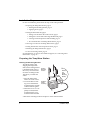
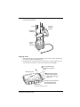
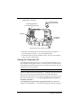
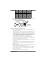
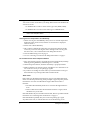
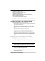
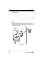
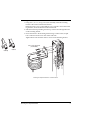
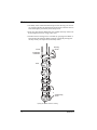
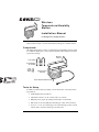
Wireless
Temp e r at u r e/H u mi di ty
Stat i o n
I n s tal l at i o n Ma n u al
For Vantage Pro® or Vantage Pro Plus™
The Wireless Temperature/Humidity Station, referred to as the Temp/Hum
Station in this manual, is for use with Wireless Vantage Pro® weather stations.
Components
The Temp/Hum Station consists of a temperature and humidity sensor located
in a radiation shield, plus a sensor interface module and transmitter located in
a protective housing.
Mounting
Bracket
1-1/2" U-Bolts
1/4" Flat Washers
1/4" Hex Nuts
3-Volt
Lithium
Battery
Radiation Shield
Assembly
Sensor Interface Module Housing
Tools for Setup
In addition to the hardware provided, you will need some or all of the following materials:
• Small Phillips-head screwdriver
• Adjustable wrench or 11/32" wrench and 7/16" wrench
• Ballpoint pen or paper clip (small pointed object of some kind)
• Drill and 3/16" (5 mm) drill bit (if mounting on a flat, vertical surface)
• Four 1/4" x 1-1/2" (6 x 38 mm) lag screws (if mounting on a flat, vertical
surface) and a wrench to fit the lag screw hex head.
Product # 6380
Installation Steps
For ease of installation, please follow the steps in the order presented.
• Preparing the Temp/Hum Station, page 2
• Rotating the Mounting Bracket, page 2
• Applying Power, page 3
• Setting the Transmitter ID, page 4
• Setting Console Station ID on the Console, page 5
• Setting the Console Station ID using WeatherLink, page 6
• Viewing Current Temperature and Humidity, page 6
• No Communication with Temp/Hum Station?, page 6
• Choosing a Location for the Temp/Hum Station, page 7
• Testing Transmission from Proposed Location, page 7
• Mounting the Temp/Hum Station, page 8
• A Note on Securing Cables, page 11
See “Maintenance” on page 10. For Technical Support, see “Contacting Davis
Instruments” on page 11.
Preparing the Temp/Hum Station
Rotating the Mounting Bracket
To facilitate packing and
shipping the Temp/Hum
Station, the mounting bracket
is installed upside down at
the factory. You will need to
rotate the mounting bracket
180° before you install the
station.
Remove
Mounting
Screws
Remove
and
Rotate
Mounting
Bracket
1. Place the Temp/Hum
Station on a level surface.
2. Loosen the three mounting screws that hold the
mounting bracket and the
radiation shield together.
Radiation
Shield
Assembly
3. When the screws are completely loosened, lift the
mounting bracket away
from the radiation shield.
4. Rotate the mounting bracket and replace it on the radiation shield.
2
Installation Steps
5. Fasten the mounting bracket in place using the three long screws as shown
in the illustration below.
4" Bolts
Re-install
Mounting
Bracket
Lock Washers
Flat Washers
Radiation
Shield
Assembly
Applying Power
1. Turn the main part of the ISS upside down. This is the part that includes the
rain collector and the radiation shield.
2. Push back on the two plastic latches to release the cover, then open the cover.
You should now be able to see the sensor interface module (SIM).
1 Use your thumbs to push
back on the two (2) plastic
latches.
SIM Housing Cover
2
With the latches pushed
back, use your fingers to
lift up on the corner edges
of the cover.
Optional Screw Fastening Holes.
Use self-threading screws:
#6 x 0.5" (3.5mm x 12 mm)
SIM Housing
Opening the SIM Housing Cover
Preparing the Temp/Hum Station
3
3. Verify that the temp/hum sensor cable is plugged into the receptacle labeled
“TEMP HUM” on the SIM.
Cable Routing Channels
(press cables fully into channel)
3-Volt Lithium Battery
(wireless models only)
Temp/Hum
Transmitter ID
DIP Switches
Temp/Hum Station Sensor Interface Module (SIM)
4. Insert the 3-volt lithium battery into the battery holder, matching the “+”
sign on the battery with the “+” sign on the battery holder.
5. Consult this drawing to locate the DIP switches. You will work with them
when you set the transmitter ID.
Setting the Transmitter ID
Your Temp/Hum Station must be set to one of eight transmitter IDs. You set
the transmitter ID using DIP switches #1, 2 and 3, located on the SIM near the
battery holder. The transmitter and receiver communicate with each other only
when both are set to the same ID.
Note: DIP switch #4 is used for transmission testing and does not affect the ID.
The factory default transmitter ID setting is ‘1’. Looking at the table on the next
page, you can see that means the DIP switches are in the OFF position.
Since the ISS is included with every Wireless Vantage Pro, the console is set at
the factory to find the ISS on ‘1’. Set your Temp/Hum Station to a different
transmitter ID number.
Use a ballpoint pen or paper clip to toggle DIP switches #1, 2, and 3. The
settings for transmitter IDs 1 – 8 are shown in the table on the following page:
4
Setting the Transmitter ID
ID CODE
#1 (default)
#2
#3
#4
#5
#6
#7
#8
SWITCH 1
off
off
off
off
ON
ON
ON
ON
SWITCH 2
off
off
ON
ON
off
off
ON
ON
SWITCH 3
off
ON
off
ON
off
ON
off
ON
Use this table to ensure that each wireless transmitting station in your system is
broadcasting on its own transmitter ID.
Battery Holder
ON
1
2
3
4
Transmitter ID
Switches
Test Indicator LED
DIP Switches in Top-right Corner of SIM (Illustration has been enlarged for clarity)
Setting Console Station ID on the Console
1. Put your console into Setup Mode — press and hold the DONE key and
press the DOWN arrow key.
The console will show you Screen 1: Transmitters. You should see the words:
“RECEIVING FROM...” and “STATION NO.” followed by the transmitter
IDs that your console detects. One of these should be the ID number you just
set on the Temp/Hum Station transmitter. If you don’t see it, make sure the
console is within 10' of the transmitter, and verify that you set the DIP
switches correctly. If you still don’t see it, go to “TEST mode”.
2. Press the DONE key to move on to Screen 2: Selecting Transmitters.
Setup Mode – Screen 2 is where you will set the console to recognize signals
on that ID as coming from a Temp/Hum Station.
3. Press the LEFT or RIGHT arrow key, or the STATION key, to scroll through
transmitter IDs.
When you see the ID you chose for the Temp/Hum Station, use the UP or
DOWN arrow keys to activate reception of that ID code. Make sure the
screen shows “ON”.
4. Press the GRAPH key to change the type of station assigned to that transmitter ID.
Press the GRAPH key until “TEMP HUM” appears.
5. If you don’t see a 4X next to the station type, press and hold the TEMP key
then press the HI/LOW key once. A 4X should appear next to “TEMP
HUM” on the console LCD.
6. To exit Setup Mode, press and hold the DONE key.
Setting the Transmitter ID
5
Setting the Console Station ID using WeatherLink
You can also set the console ID for your Temp/Hum Station from WeatherLink
version 5.2 or later.
• In WeatherLink 5.2 and 5.3 set the station type to ISS (TEMP/HUM).
• In WeatherLink 5.4 or later set the station type to TEMP HUM 4x.
Note: These settings are required because of changes made to the transmitter in this
version of the Temp/Hum Station.
Viewing Current Temperature and Humidity
1. On the console, press the TEMP key until you see an ‘outside’ temperature
displayed on the console screen, with the correct Station No. displayed
above or below it.
2. Do the same with the HUM key.
3. This confirms communication between your Temp/Hum Station and the
console. If you are not receiving the sensor readings on the console go the
the next section, “No Communication with Temp/Hum Station”.
4. Close the SIM housing cover. See page 3.
5. Go on to “Choosing a Location for the Temp/Hum Station” on page 7.
No Communication with Temp/Hum Station
1. First, verify that the console is powered and is not in Setup Mode (exit Setup
Mode by pressing DONE key and holding it for a moment).
2. On the Temp/Hum Station, check that the battery is properly installed.
3. Walk around the room with the console, standing for a few moments in various locations to see if you are picking up signals.
4. If you don’t see readings no matter where you stand with the console, put
the transmitter on your Temp/Hum Station in TEST mode.
TEST mode
DIP switch #4 on the SIM (see illustration on page 5) is the TEST DIP-switch.
Switch it to the ON position using a ball-point pen or paper clip. This puts the
transmitter in Test Mode. An LED indicator light will flash each time it
transmits:
• The LED will immediately flash once to show that the light itself functions.
• Then it will flash each time the transmitter broadcasts a signal, which
should be every 10 seconds.
If the LED flashes only once and then remains dark, there is a problem with the
transmitter. See “Contacting Davis Instruments” on page 11.
If the LED flashes repeatedly but your console isn’t picking up a signal
anywhere in the room, it could be related to one of the following causes:
6
Setting the Transmitter ID
1. The DIP switches were not correctly set on the Temp/Hum Station.
Review the procedure on page 4.
2. The ID was not correctly set on the console.
Review the procedure on page 5.
3. Reception is being disrupted by RF (radio frequency) interference.
4. There is a problem with the console.
See “Contacting Davis Instruments” on page 11.
Note: Remember to set the Test DIP switch OFF when you’re finished testing wireless
transmission. If it is left ON, the blinking LED will reduce battery life significantly.
Choosing a Location for the Temp/Hum Station
Consider the following factors as you choose a location:
• Do not mount the station near any source of cold or heat that might distort temperature measurements.
• The station’s radiation shield works best in a location with a steady
breeze. Mount it away from fences, buildings, trees, or other obstructions.
• Mount the station over vegetation or soil if possible.
• Do not install over or near sprinklers. The radiation shield is not
designed to protect sensors from water that is sprayed upwards.
• If mounting on a building, the preferred location is on the north side in
the Northern Hemisphere and on the south side in the Southern Hemisphere. Mount it on the side that receives the least sunlight throughout
the day.
Testing Transmission from Proposed Location
It is very important to test reception from the proposed location before
permanently mounting the Temp/Hum Station.
• Place the Temp/Hum Station at the intended mounting site, or have
someone hold it there, so you can walk around with the console for a few
minutes.
Note: Rotating the antenna on the station and on the console may help improve
reception. Generally, for best reception the two antennas should be oriented
parallel to each other.
• Test wireless reception anywhere you might want to use or mount your
console now or in the future. Take your time.
• If you aren’t picking up strong signals where you intend to place your
console, better to move the Temp/Hum Station now than after it has
been mounted. Experiment.
Choosing a Location for the Temp/Hum Station
7
Mounting the Temp/Hum Station
The Temp/Hum Station can be mounted on a pole or on a vertical surface such
as a wooden post or wall.
Mounting on a Pole
Use a pole having an outside diameter between 1" and 1-1/4" (25 – 31 mm).
1. Slide the stud ends protruding from the top of the station through the holes
on the mounting bracket.
2. Secure the station to the mounting bracket using a #8 flat washer, #8 split
lock washer and #8 hex nut one each of the stud ends.
Tighten the hex nuts until the station is secure on the mounting bracket.
3. Hold the mounting bracket against the pole. Put two U-bolts around the
pole and insert the ends through the holes in the back of the mounting
bracket.
4. Secure the mounting bracket using 1/4" flat washers and 1/4" hex nuts.
Tighten four set of the washers and hex nuts until the mounting bracket is
firmly mounted on the pole.
1-1/2" U-Bolts
1/4" Flat Washer
1/4" Hex Nut
Mounting on a Pole
8
Mounting the Temp/Hum Station
Mounting on a Vertical Surface
1. Using four 1/4" x 1-1/2" lag screws (not included), attach the mounting
bracket to the surface in the desired location.
Drill holes using a 3/16" (5 mm) drill bit. Use a carpenter’s level when marking the holes, to ensure that the bracket will be level.
2. Slide the stud ends protruding from the top of the station through the holes
on the mounting bracket.
3. Secure the station to the mounting bracket using a #8 flat washer, #8 split
lock washer and #8 hex nut on each of the stud ends.
Tighten the hex nuts until the station is secure on the mounting bracket.
1/4" x 1-1/2" Lag Screws
(not included)
Cable Tie
Cable Clip
Mounting the Temp/Hum Station to a Vertical Surface
Mounting the Temp/Hum Station
9
Maintenance
• The ability of the radiation shield to keep fresh air flowing over the sensors will be reduced if the shield plates become dirty. Clean the surfaces
of the shield plates periodically with a damp cloth.
• Keep areas between the shield plates free of debris that may obstruct air
flow. Examples are leaves, twigs, webs, nests.
• DO NOT remove nesting insects or animals by spraying insect killer of
any kind into the radiation shield. Chemicals could easily damage the
circuitry inside your temperature/humidity station.
4" Bolts
Mounting
Bracket
Lock Washers
Flat Washers
Plates
Temp/Humidity
Sensor
Opening the Radiation Shield for Cleaning
10
Maintenance
A Note on Securing Cables
To prevent fraying or cutting of cables, secure them so they will not whip about
in the wind. Secure a cable to a metal pole by wrapping electrical tape around
them both. Make sure cables are secure by placing clips or ties approximately
every 3 – 5' (1 – 1.6 m).
Cable Tie
Cable Clip
Note: Do not use metal staples or a staple gun to secure cables. Metal staples—
especially when installed with a staple gun—have a tendency to cut the cables.
Contacting Davis Instruments
If you have questions about your Temp/Hum station, or encounter problems
installing or operating the station, please contact Davis Technical Support.
Note: Please do not return items to the factory for repair without prior authorization.
(510) 732-7814 for Technical Support, Monday – Friday, 7:00 a.m. – 5:30 p.m.
Pacific Time.
(510) 670-0589 Fax to Customer Service or Tech Support.
[email protected] E-mail to Technical Support.
[email protected] General e-mail.
www.davisnet.com Copies of User Manuals are available on the “Support”
page. Watch for FAQs and other updates. Subscribe to the e-newsletter.
Specifications
• Temperature range: –40 to 140° Fahrenheit (–40 to 60° Celsius)
• Wireless transmission frequency: 916.5 MHz
868.35 MHz for overseas version – Product # includes “XA”
• Transmitter ID codes: 8 user-selectable
• License: low power (less than 1 mW), no license required
• Primary power input: CR-123A 3-volt lithium battery
• Secondary (backup) power: Optional Vantage Pro AC power adapter
A Note on Securing Cables
11
FCC Part 15 Class B Registration Warning
This equipment has been tested and found to comply with the limits for a class B digital device, pursuant to
Part 15 of the FCC Rules. These limits are designed to provide reasonable protection against harmful interference in a residential installation. This equipment generates, uses and can radiate radio frequency energy
and, if not installed and used in accordance with the instructions, may cause harmful interference to radio
communications. However, there is no guarantee that interference will not occur in a particular installation.
If this equipment does cause harmful interference to radio or television reception, which can be determined
by turning the equipment off and on, the user is encouraged to try to correct the interference by one or more
of the following measures:
•
Reorient or relocate the receiving antenna.
•
Increase the separation between the equipment and receiver.
•
Connect the equipment into an outlet on a circuit different from that to which the receiver is connected.
•
Consult the dealer or an experienced radio/TV technician for help.
Changes or modifications not expressly approved in writing by Davis Instruments may void the user's
authority to operate this equipment.
Product Numbers: 6380
Davis Instruments Part Number: 7395.142
Wireless Temperature/Humidity Station Installation Manual
Rev B (May 14, 2003)
This product complies with the essential protection requirements of the EC EMC Directive 89/336/EC.
Copyright © 2003 Davis Instruments Corp. All rights reserved.
3465 Diablo Avenue, Hayward, CA 94545-2778 U.S.A.
510-732-9229 • Fax: 510-732-9188
E-mail: [email protected] • www.davisnet.com