1
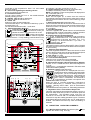
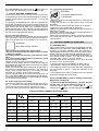
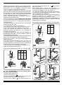
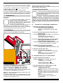
INSTRUCTION MANUAL FOR TIG WELDING MACHINE
IMPORTANT SAFETY INFORMATION!!!
READ THE FOLLOWING INSTRUCTIONS CAREFULLY
BEFORE INSTALLATION, USE, OR SERVICING OF THIS
UNIT. PAY CLOSE ATTENTION TO THE SAFETY RULES
AND CONTACT YOUR DISTRIBUTOR IF YOU DO NOT
UNDERSTAND SOME OR ALL OF THE POINTS COVERED
IN THESE INSTRUCTIONS.
1 SAFETY RULES CONCERNING THE USE OF THIS
WELDING MACHINE
1.1 INTRODUCTION
All people authorized to use this machine should read the
following instructions manual before using or servicing this
unit.
A REMINDER: YOUR SAFETY DEPENDS ON YOU!!!
Always follow all safety regulations and instructions when
using this machine. It is your responsibility to protect
yourself and others against the risks related to the operation
of this welding machine. The operator must be familiar with
and observe all the safety rules regarding the safe operation
and maintenance of this welding machine.
NOTHING REPLACES GOOD COMMON SENSE !!!
1.2 GENERAL PRECAUTIONS
1.2.1 Fire
• Avoid causing fires due to sparks, slag,
hot metal and spatter which are produced
during normal welding operations.
• Make sure that a suitable fireextinguisher is located near the welding sight.
• Remove all flammable material within 30 feet of the
welding area.
• Do not weld containers (tanks or drums) containing
flammable material, even when empty.
• Allow the welded metal to cool down before touching it or
putting it into contact with flammable material.
• Do not weld structures with hollow spaces containing
flammable substances.
• Do not work in conditions where there are high concentrations of combustible vapours, gases, or flammable dust.
• Always check the work area half an hour after welding so
as to make sure that no fire has started.
• Do not keep any flammable material such as lighters or
matches in your pockets while using this equipment.
1.2.2 Burns
• Protect your entire body by wearing fire-proof clothing
This will protect your skin against burns caused by: ultraviolet radiation given off by the arc, sparks and molten slag..
• The protective clothing should include: gloves, a hat, and
high shoes. Your shirt collar and pocket flaps should be
buttoned , and cuff-less trousers should be worn to prevent
contact with sparks and molten slag.
• Wear a helmet equipped with the appropriate lens shade
and a clear glass cover plate. This is imperative when
welding, cutting, and chipping to protect your eyes from
ultra-violet arc rays and molten spatter. Replace the glass
cover plate when cracked or covered with spatter etc.
• Do not wear clothing spotted with oil or grease as a spark
may set them on fire.
• Hot metal, electrode stubs and workpieces, should never
be handled without gloves.
• First-aid equipment and a qualified first-aid person should
10
always be available when welding, unless medical facilities
are in the immediate vicinity, to treat flash burns of the eyes
and skin burns.
• Ear plugs should be worn when working in the overhead
position or in confined spaces. A hard hat should be worn
when others are working overhead.
• Flammable hair sprays and gels should not be used by
those persons intending to weld.
1.2.3 Fumes
Welding operations produce harmful fumes and
metal dusts which may be hazardess to your
health, therefore:
• Work in well-ventilated areas.
• Keep your head out of the fumes.
• In closed areas, use a fume exhaust system, preferrably
placed under the welding area if possible.
• If ventilation is inadequate, use an approved respirator
set.
• Clean the metal to be welded of any solvents or halogen
degreasers which give rise to toxic gases. During some
welding operations clorine solvents may be decomposed
by arc radiation thus creating phosgene gas.
• Do not weld coated metals or those containing lead,
graphite, cadmium, zink, chrome, quicksilver, or mercury
unless you have an approved respirator set.
• The electric arc creates ozone. Long exposures to high
ozone concentrations may cause headaches; nasal, throat
and eye irritation; as well as congestion and chest pains.
WARNING: NEVER USE OXYGEN FOR VENTILATION.
• Gas leaks in confined spaces should be avoided. Leaked
gas in large quantities can dangerously alter oxygen levels
in the air surrounding the weld sight. Do not place gas
cylinders in confined spaces.
• DO NOT WELD where solvent vapors can be drawn into
the welding shield atmosphere or where arc rays can come
into contact with even minute quantities of trichloroethylene
or perchloroethylene.
1.2.4 Explosions
• Do not weld above or near containers under
pressure.
• Do not weld in environments containing
explosive dusts, gases or vapours.
This welding machine when used for TIG welding uses
ARGON gas to shield the arc. Special precautions must be
taken when transporting, handling, and connecting gas
cylinders.
A) GAS CYLINDERS
• NEVER DEFACE or alter the name, number, or other
markings on a cylinder. It is illegal and dangerous!
• Do not use cylinders whose contents are not clearly
identified.
• Do not directly connect cylinder to the unit without using
a pressure regulator.
• Handle and use pressure cylinders with care and in
conformity with existing safety standards.
• Do not use leaking or damaged cylinders.
• Do not use cylinders which are not well secured.
• Do not transport or move cylinders without the protection
of the installed valve and protective valve cap.
• Do not lift cylinders off the ground by: their valves or caps,
by chains, by slings, or by magnets.
• Never try to mix gases in a cylinder.
• Never refill a cylinder!
• Never lubricate the cylinder valve with oil or grease.
• Never allow an electrode to touch a cylinder!
• Do not expose cylinders to excessive heat, sparks, molten
slag or flames.
• Do not tamper with the cylinder valve.
• Do not try to loosen tight valves by means of a hammer,
a wrench, or any other object.
B) PRESSURE REGULATORS
• Keep pressure regulators in good condition. Damaged
regulators may cause damages or accidents. They should
be repaired by skilled personnel only.
• Do not use regulators for gases other than those for which
they were manufactured.
• Never use a leaking or damaged regulator.
• Never lubricate regulators with oil or grease.
C) HOSES
• Replace hoses which appear to be damaged.
• Keep hoses unwound in order to prevent kinks.
• Keep the excess hose neatly wound and out of the working
area in order to avoid damage.
• Cylinder fittings should never be modified or exchanged.
1.2.5 Radiation
Ultra-violet radiation emitted by arc rays may
damage your eyes and burn you skin. Therefore:
• Wear proper clothing and helmet.
• Do not use contact lenses!! The intense heat created
by the arc may cause them to stick to the cornea.
• Use a mask or helmet equipped with lens shades that have
a minimum DIN rating of 10
• Warn people in the area surrounding the welding sight that
you are going to be welding.
Remember: the arc may dazzle or damage the eyes. It is
considered dangerous up to a distance of 15 meters (50
feet). Never look at an arc with the naked eye.
• Prepare the welding area so as to reduce the reflection
and transmission of ultra-violet radiation: paint walls and
exposed surfaces in black to reduce reflection, install
shielding systems or curtains to reduce the transmission
of ultra-violet rays.
• Replace protective lenses whenever damaged or broken.
1.2.6 Electric shock
Electric shocks are hazardous and potentially fatall!!
• Do not touch live electrical parts.
• Insulate yourself from the workpiece and the
ground by wearing insulated gloves and clothing.
• Keep garments (gloves, shoes, hats, clothing) and body
dry.
• Do not work in humid or wet areas.
• If you are welding near a body of water take precautions
to ensure that the machine cannot fall into the water.
• Avoid touching or holding the workpiece by hand.
• Should you work in a dangerous area or close to one , use
all possible precautions.
• Stop welding immediately if you should feel even the
slightest sensation of electric shock. Do not use the
machine until the problem is identified and corrected.
• Often inspect the mains input cable.
• Disconnect the power input cable from the mains supply
before replacing cables or before removing the unit covers.
• Do not use the unit without protection covers.
•Always replace any damaged parts withGENUINECEBORA
SPARE PARTS.
• Never disconnect any of the unit's safety devices.
• Make sure that the mains power supply line is equipped
with a good electrical ground.
• Servicing of the machine must be done by qualified
personnel who aware of the risks involved with the high
voltage levels necessary to make the machine operate.
1.2.7 Pacemaker
Magnetic fields created by the high currents in the weld
circuit can affect pacemaker operation. Persons wearing
electronic life support equipment (pacemakers) should
consult their doctor before going near any arc welding,
gouging, cutting, or spot welding equipment in operation.
1.2.8 Noise
These power sources alone do not produce noise levels
exceeding 80 dB. The AC TIG welding procedure,
however, may produce noise levels in excess of 80
dB in which case the machine take operator must
take the necessary safety precations as prescribed
by the national take safety regulations.
2 GENERAL TECHNICAL DESCRIPTIONS
2.1 SPECIFICATIONS
These machine are constant current power sources, suitable
for both the TIG and Manual Metal Arc welding procedures.
These technologically advanced, high quality power sources
incorporate, single current adjustment range, square wave
technology and total central of the welding current.
Upon receiving and unpacking the machine, make a careful
inspection to ensure that there are no damaged parts. Should
there be a claim for losses or damages it must be made by the
purchaser directly to the shipper who handled the goods.
When requesting information about this welding machine
please state the machine’s part number and serial
number to ensure receiving accurate information relating
to your machine.
2.2 DESCRIPTION OF TECHNICAL SPECIFICATIONS
N˚
1
EN 60 974-1
U0
V
V
U0
U1
1~ 50/60 Hz
I. Cl.
H
IP 21
PROTEZIONE TERMICA
THERMAL PROTECTION
PROTECTION THERMIQUE
TERMISCH GESCHÜTZ
PROTECCION TERMICA
-
V
- / - - - / X
I2
U2
- / - - - / X
I2
U2
I1 A I1 A I1 A
I1
-
MADE IN ITALY
VENTILAZIONE FORZATA
FORCED VENTILATION
VENTILE
KUHLART F
VENTILACION
11
IEC 974.1This machine is manufactured according to the
EN 60947.1 IEC 974 international standard.
N°. .......... Machine Serial Number which must appear on
requests or inquiries concerning the machine.
1
Single-phase transformer-rectifier.
Drooping characteristic.
1
2
3
4
5
6
............... Shielded Metal Arc Welding. (Stick Welding)
1
2
3
4
5
6
1
2
3
4
5
6
............... TIG (Tungsten Inert Gas) welding.
1
U0. ........... Secondary no-load voltage
X. ............ Duty-Cycle Percentage
The duty-cycle is the number of minutes the
machine can operate (arc on) within a ten minute
period without overheating. The duty cycle varies
according to the output current.
I2. ............ Output welding current
U2. ........... Secondary voltage, welding current= I2
U1. ........... Nominal supply voltage
1~50/60Hz Single-phase input supply at 50 or 60 Hz
I1. ............ Input Amps absorbed corresponding to different
output levels (I2).
IP21. ....... Protection class of the machine's case
The 1 in the singles digit place means that this
unit is not fit to work outdoors in the rain.
S. ........... Fit to work in hazardous areas (ept. item 235).
NOTE: .... This machine has also been designed to work
in class 3 pollution areas (see IEC 664)
3 INSTALLATION
3.1 SET UP AND INSTALLATION
Upon receiving the machine, unpack it from its carton. Install
the handle and the wheels.
Place the machine in a ventilated area.
Dust, dirt, or any other foreign material that might enter the
machine may restrict the ventilation which could affect the
machine's performance. Keep the machine as clean as
possible.
3.2 INPUT POWER CONNECTIONS
WARNING!!
ELECTRIC SHOCK CAN KILL
• This machine must be installed by skilled personnel.
• Make sure that the input power plug has been disconnected
before inspecting, maintaining, or servicing.
• Connect the yellow-green lead of the machines power/
supply cable to a good electrical ground.
• After a final inspection, the machine should be connected
to the input supply voltage marked on the input power cord.
• If you wish to change the input supply voltage, remove the
upper cover of the case, locate the voltage-changing
terminal board and arrange the connections as shown in
figure 1.
3.3 PRECAUTIONS
The fan is activated by generator heat. Before opening
the machine for any reason, it is extremely important to
turn the machine off!
10 9
10 9
8 7
6
5
8 7
6
5
10
9
2
4
3
2
4
3
2
3
1
1
8
7
4
5
10 9
8 7
6
5
4
3
2
1
10 9
8 7
6
5
4
3
2
1
10 9
8 7
6
5
4
3
2
1
6
5
4
6
10 9
8 7
10 9
8 7
3
6
5
4
3
6
5
4
3
2
2
1
2
1
1
3.4 PROTECTION AGAINST HIGH FREQUENCY
INTERFERENCE
The circuit generating high frequency inside the machine
can be compared to a radiotransmitter.
Incorrect installation of the machine may cause radio and
TV disturbance.
There are 4 sources of High Frequency Interference:
1) Interferences irradiated by the welding machine
2) Interferences irradiated by the welding cables
3) Interferences irradiated on the supply line
4) Interferences intercepted and irradiated by ungrounded
metal objects.
TO REDUCE THE RISK OF HF INTERFERENCE, INSTALL
THE MACHINE ACCORDING TO THESE INSTRUCTIONS.
• Keep the line connections between the machine and the
power input source as short as you can, possibly housing
the input cable inside a metal tube which is connected to an
electrical ground, buried in the ground.
• Keep the welding cables as short as possible.
Their length should not exceed 7/8 meters (25 feet). If If
possible wind them together with tape.
• Make sure that there are no cuts, burns, or tears in the
rubber insulation of the welding cables. Wires with high
natural-rubber content can better withstand high-frequency
losses.
•Make sure that all the connections are snug and that the
welding torch is in good condition. These steps will help to
reduce High Frequency losses.
• Keep the machine case panels and covers closed during
operation.
• All wires within a 15 meter range must be enclosed in
metal tubes and these tubes have to be grounded.
Helicoidal-type hoses are not suitable.
• When the machine is used inside a metal structure,
several groundings are recommended.
NEVER USE WATER PIPES AS GROUND CONDUCTORS
4
DESCRIPTION OF THE MACHINE'S FEATURES
A -Receptacle for remote control plugs
Various accessories for regulating the welding current are
12
connected to this receptacle for both T.I.G. and coated
electrode welding.
B - Device for regulating the welding current
It gets connected to receptacle A
C - Procedure selector
You can select either the T.I.G. or the coated electrode
(SMAW) welding process.
D - ON/OFF light or Led for article 235
It remains lit while the machine is on.
E - Yellow led
It lights up when the thermostat trips.
The thermostat trips if the machine's rated duty cycle is
exceeded (see 2.2).
The machine shuts down until it cools down.
F - Manual/ Automatic Selector :
• Manual position : press the button and the
machine delivers current to the torch, when you
release the button, the current flow is cut off.
• Automatic position : push the torch button
once and release it and the machine supplies
current to the torch. To stop welding, press the button once
E
T
A
B
2
9
5
5
6
8
3
10
1
5
6
4
7
6
4
7
L
7
3
8
3
8
3
8
2
9
2
9
2
9
1
1
10
1
10
➞
F
P
➞
➞
C
10
GAS
➞
A
O
➞
7
➞
4
4
V
D
6
5
M
R
A
Q
~
~
and release it and the current flow is cut off.
G - Digital Amperometer (optional) (exept item 235)
It indicates the welding current in Amperes.
NOTE: The welding current can be preset and displayed on
this instrument (see 4.1).
H - Red Shut Down Led.
When this led lights up, it means that the machine
automatically shuts down because the safety device which
reduces the risk of electric shock is not functioning. (exept
item 235)
I - Green Protection Led (exept item 235)
This led indicates that the device which reduces the risk of
electric shock is functioning normally and it should remain lit
while the machine is in operation. If it is not lit, there might
be a problem.
L - Post-Gas Regulation
This knob regulates the period of time in seconds that the
shielding gas will continue to flow after a welding operation
is terminated.The range runs from 0.3 to 30 sec.
M - High Frequency Arc Start Selector
In the coated-electrode(SMAW) mode it is automatically excluded. When A.C. T.I.G. welding it must be
connected all of the time and when D.C. T.I.G.
welding it can be disconnected if you want to
"scratch start" the arc .
N - Main Power Switch
This switch turns the machine ON and OFF. (Note: The ON/
OF power switch on Article 235 is located on the back panel
of the machine.)
O - Up Slope Time Regulation
This knob regulates the time it takes the current to climb
from 0 to the amp value set by the amp potentiometer (Knob
B). The regulation range runs from 2.2 to 10 sec.
P - Gas Fitting (1/4 gas)
To connect the T.I.G. torch gas hose to the machine.
Q - Torch Control Receptacle
Insert the torch control plug in this receptacle.
It functions only when T.I.G. welding is selected.
R - Alternate Current (A.C.)-Direct Current (D.C.) Selector
• Select to A.C.: to weld aluminum, brass and magnesium
In T.I.G.
• Select to D.C.. to weld all other materials in TIG and to weld
coated electrdodes (SMAW).
S - Balance Control (exept item 235)
Using this knob, the semiperiods of the A.C.
square wave can be modified. This is especially
handy when you are TIG welding aluminium.
The point at which the two semi-waves are
balanced is the zero position. At the 0 position
less current is absorbed, the electrode is
consumed less, and there is an optimal ratio
between bead width and depth.
When you want to increase penetration, rotate knob S
clockwise towards the (+); viceversa, when you want to
increase cleaning action rotate knob S anticlockwise
towards (-).
This feature functions only when A.C. TIG welding is selected.
T - Regulation of the Current Down Slope Time
This knob regulates the time it takes the welding current to
pass from Amp value set by knob B to 0 at which point the
arc extinguishes. The regulation range runs from 0.2
seconds to 10 seconds and it is activated whenever the
command to stop the welding operation is given. The down
slope feature allows the crater at the end of weld seam to
be filled. This feature functions only when TIG welding is
selected.
1
0
1
2
2
3
3
4
4
U
B V
G
H
E
I
N
D
V
6
5
4
A
7
8
3
2
9
10
1
1
A
0
5
1
5
6
4
4
7
6
5
7
6
4
7
2
2
3
8
3
8
3
2
9
2
9
2
8
3
3
-
9
4
4
5
5
+
1
10
1
10
1
GAS
10
GAS
~
A S
O T C R
A.C.
M
F
D.C.
L
P
Q
~
5
5
4.1 PRESETTING OPERATING CURRENTS
4.1.1 Welding with electrode: Set selector (C)to
regulate the current using knob (V).
then
13
4.1.2 TIG welding: Set selector (C) to
then push the
torch button and regulate the current using knob (V).
5.3 Connecting the gas hose.
WARNING!!
5 OUTPUT WELDING CONNECTIONS
CYLINDERS CAN EXPLODE
IF DAMAGED
• The welding circuit should not deliberately be
in direct or
iindirect contact with the ground conductor if not in the
workpiece.
• If grounding is deliberately done with the workpiece by
means of a ground wire, the connection must be as direct as
possible and it must be made with a wire having a section at
least equal to the ground lead. The connection must be
made to the workpiece and it msut be in the same place as
the ground lead either by using the ground lead clamp or a
second ground clamp placed close by.
5.1 Connecting the TIG torch.
Based on your work requirements, always use the shortest
torch (the length of the torch cable is intended) possilbe in
order to reduce the risk of HF interference to a minimum.
• Keep the cylinders in an upright position by chaining them
to their support.
• Keep the cylinders in a place where they cannot be
damaged.
• Do not lift the machine with the cylinder on its support.
• Never touch the cylinder with an electrode.
• Keep the cylinder away from the welding area and uninsulated electric circuits.
• Cylinders containing inert gas have to be equipped with a
pressure reducer and a flowmeter.
• After having positioned the cylinder, connect the gas hose
that comes out from the rear of machine to the pressure
reducer output.
6
WELDING PERAMETER GUIDELINES
WARNING!!
ELECTRIC SHOCK CAN KILL
• Do not touch uninsulated live electric parts
• Do not touch the hot electrode either with your hands
or with your clothes.
• Insulate yourself both from the ground and the workpiece.
• To avoid receiving high-frequency discharges, keep
the torch in good condition.
• Before connecting the torch turn the machine off.
• Insert the male plug of the torch cable into the negative
terminal and turn to the right until the connector locks. Make
sure that the fit is tight.
Select the diameter and type of electrode on the basis of
the metal to be welded and its thickness . The number of
output Amps needed and DC or AC welding will also
condition the selection of the proper electrode.
Connect the gas hose which comes out from the torch to
the 1/4 gas fitting (letter P) on the machine's front panel.
Insert the torch control plug into receptacle (Q) also located
on the machine's front panel.
5.2 Connecting the ground clamp
• Connect the male plug of the work lead (ground cable) to
the + or - terminal in accordance with the procedure used.
Insert and turn clockwise until the connector is snug.
• Connect clamp end of the work lead to the workpiece.
6.1 SHIELDING GAS
• The most commonly used shieling gas is ARGON ,however,
ARGON mixtures with a max. of 2% HYDROGEN can also
be used for welding stainless steel, and HELIUM or
ARGON/HELIUM mixtures can be used for welding copper.
These mixtures increase the heat generated by the arc.
If you are using helium gas, increase the flow rate (l/min) so
as to obtain a ratio 10 times the size of the electrode
(example: diam. 1.6x10 = 16 l./min. helium).
• Use protection lenses with shades D.I.N. 10 for up to 75A
and D.I.N. 11 for 75A and above.
• Inert gas flow must be regulated to a value ( l/min.)
approximately 6 times the diameter of the electrode.
• If accessories such as gas lenses are used, the gas flow
can be reduced to approx. 3 times the diameter of the
electrode.
• The diameter of the ceramic nozzle must be 4 to 6 times
larger than diameter of the electrode.
6.2 AC TIG WELDING is used for welding: Aluminium,
Magnesium, and Bronze
• To achieve the best welding results, you must become
familiar with all of the machine's functions
• Position selector (R) on A.C., selector (M) on
and
selector (C) on
(TIG). All other settings depend on the
ELECTRODE AND CURRENT SELECTION GUIDE
Max. Penetration pos.
Zero balanced pos.
Max. Cleanness pos.
▲
Tungsten
2% Thorium
Tungsten
pure
Tungsten
0.8 % ZR
Tungsten
pure
Tungsten
0.8 % ZR
Tungsten
pure
tungsteno
0.8 % ZR
0.5mm - 0.02"
15A ÷ 40A
-
-
10A ÷ 20A
5A ÷ 20A
-
-
1mm - 0.04"
25A ÷ 85A
-
-
20A ÷ 30A
20A ÷ 60A
-
-
1.6mm - 1/16"
70A ÷ 150A
50A ÷ 100A
70A ÷ 150A
30A ÷ 60A
50A ÷ 80A
20A ÷ 40A
30A ÷ 60A
2.4mm - 3/32"
150A ÷ 250A
100A ÷ 160A
140A ÷ 235A
60A ÷ 120A
80A ÷ 140A
40A ÷ 100A
60A ÷ 120A
3.2mm - 1/8"
200A ÷ 350A
150A ÷ 210A
225A ÷ 325A
80A ÷ 160A
100A ÷ 180A
60A ÷ 140A
80A ÷ 160A
4mm - 5/32"
300A ÷ 400A
200A ÷ 275A
300A ÷ 400A
100A ÷ 240A
150A ÷ 280A
80A ÷ 200A
150A ÷ 250A
Electrode. Type
Ø
▲
14
without touching the workpiece and on
if you wish to
touch start the arct.
When scratch starting without High Frequency, it is
recommended that you use the max. up slope time 8 sec.
• To preset the welding current, see section 4.1.
• To select the welding program, see letter (S), section 4.
• The diameter of the filler material must be equal to or less
than the thickness of the workpiece.
• The ratio between the current to be used and the workpiece
thickness is: 20/30 Amp. per millimeter for carbon and
stainless steels; 80 Amp. per millimeter for copper.
ATTENTION! THIS RATIO MAY VARY ACCORDING TO
WORKPIECE SIZE AND IT IS ONLY MEANT TO BE AN
APPROXIMATE GUIDELINE.
ELECTRODE PREPARATION FOR D.C. TIG WELDING
D
↔
α
↔
diameter of the electrode fitted to the torch and the number
amps needed to perform a certain job.When welding aluminum,
pure tungsten ( D.I.N. color GREEN ) or zirconium tungsten
( D.I.N. color WHITE ) electrodes must be used.
• When welding, the electrode tip will tend to become
spherical. If the “ball” at the tip of the electrode is bigger than
the diameter of the electrode itself, it means that the current
you are using is too high for that electrode; the electrode
should be replaced with one of a larger diameter.
Proper electrode preparation is extremely important.
Carefully follow the steps shown.
• The post-gas time in seconds (REGULATED BY KNOB
L) must be sufficient enough for the electrode to cool down.
The electrode should have a bright, glowing tip during th
cool down period.
• To adjust the balance of the square wave ,see letter (S),
section 4. (exept item 235)
• To preset working currents, see section 4.1.
• The diameter of the filler material must be less than or
equal to the thickness of the workpiece to be welded.
• The ratio between the current to be used and the
workpiece thickness is 40 Amp/mm. E.g.: a thickness of
2 mmx40 = 80 Amperes.
ATTENTION: THIS RATIO MAY VARY ACCORDING TO
WORKPIECE SIZE AND IS ONLY MEANT TO BE AN
APPROXIMATE GUIDELINE.
• The alumina (aluminium oxide) must be removed from the
weld area to avoid aluminum oxide contamination
and the risk of pile up, both typical weld defects when
welding aluminum.
• The removal of the alumina layer can be done with
mechanical brushes. The brush disc should consist of
stainless steel wires. The alumina must be removed from
at least a 5 cm.area surrounding the weld area.
• Use protection lenses with shades of at least D.I.N. 11.
• Use pure ARGON to shield the arc.
D
L
1/16"
3/32"
1/8"
5/32"
0.12"
0.20"
0.28"
0.39"
a = 30° “ 60°
L
YES
NO
ELECTRODE PREPARATION FOR A.C. TIG WELDING
D
↔
D
d1
L
1/16"
3/32"
1/8"
5/32"
1/32"
3/64"
1/16"
0.08"
0.08"
0.12"
5/32"
0.20"
40˚
90˚
↔
d1
↔
30˚
a = 20° “ 25°
70˚÷8
70˚÷80˚
0˚
20˚
➠
L
➠
α
20˚
20˚
NO
YES
90˚
6.3 D.C. TIG WELDING is used for welding: Steel,
Stainless, Steel and Copper
• Position selector (R) on D.C.
➠
The TIG torch must be connected to the neg. terminal (-) and
the ground cable to the positive termianl (+).
10˚
➠
if you wish to start the arc
0˚
20˚
70˚÷8
0˚
➠
• Position selector (M) on
70˚÷8
➠
• Position selector (C) on
20˚
15
6.4 WELDING WITH COATED ELECTRODES (SMAW)
• This machine can weld any type of coated electrode.
• Position selector (C) on
• When led (N) lights up, you are ready to weld.
• Connect the electrode holder and the ground cable in
accordance with the polarity indicated by the electrode
manufacturer (normally the electrode goes to the + terminal).
7
MAINTENANCE
WARNING:
ALL SERVICING AND REPAIR MUST BE
DONE BY QUALIFIED PERSONNEL
• Before opening the machine case to service
or repair, turn off the machine and disconnect
the plug from the power source.
• As part of general maintenance keep the
TIG torch and the welding wires in good condition.
• Periodically clean the inside of the machine by blowing
dust and particles away with a light jet of dry air.
8 ACCESSORIES
PART N° 180 PULSED REMOTE CONTROL
PART N°182 FOOT CONTROL PEDAL
The foot pedal allows you to regulate the welding current
without having to stop welding.
9 TROUBLESHOOTING GUIDE
Turn the machine off and disconnect the power
input plug from the wall outlet before opening
the machine case to inspect or work on the
inside of the machine.,
Read the information in the following section
carefully. Problems are frequently caused by
improper positioning of the selectors on the front panel of
the machine. After having checked to be sure that all the
selectors are in the correct position, check: the line fuses
to make sure they are not blown, check that all the wires are
properly connected, and check that all the connections are
snug.
9.1
TROUBLE IN THE MACHINE CONNECTIONS
1- TROUBLE-The machine does not turn on
CAUSES-Input power cord not plugged in
-One power supply phase missing
-Machine not connected to the right supply
voltage
2- TROUBLE-The machine switches on but does not
supply current
CAUSES-Current regulating knob(B) is not inserted into
receptacle (A).
-Potentiometer (V) is damaged.
-Welding accessories not connected.
3-TROUBLE-The machine switches on but the yellow
warning light (E) remains lit and the
machine does not supply current.
CAUSES -The thermostat has tripped. Allow the machine
to cool down and then turn it on again.
4- TROUBLE-The red stop led (H) lights up
CAUSES- S.C.R. diode in short circuit.
-Damage to the control card. (exept item 235)
5- TROUBLE-The line fuses trip.
CAUSES -Installed power not sufficient
-Machine not connected to the right supply
voltage.
-Short circuit in the power transformer
-S.C.R. diodes in short circuit.
9.2 TROUBLE WITH THE T.I.G. PROCEDURE
1- TROUBLE-High-frequency failure.
CAUSES -Check that the welding cables are not
damaged.
- Shielding gas is inadequate
-Position selector (M) on
-Position selector (C) on electrode
Essential for TIG welding on thin sheet metal.
It is connected to receptacle (A) on the front panel.
PART N° 132 DIGITAL AMMETER (for article 239)
PART N° 134 DIGITAL AMMETER (for article 237)
This item indicates the welding current. The welding current
can be preset and displayed, see section 4.1.
PART N° 1326 5-meter EXTENSION CORD FOR THE
REMOTE CONTROL UNIT
The pulsed remote control unit ITEM 180 and the remote
current control devi ce (B), may be brought to welding sight
by means of this extension cord.
16
2- TROUBLE-Difficulties in starting the arc in TIG
CAUSES -Shielding gas is inadequate
- Welding current too low
-Tungsten electrode contaminated. Restore
the tip
-Electrode used was incorrect. A pure tungsten
electrode is used for AC TIG welding and a
Thoriated Tungsten electrode is for DC TIG
welding.
-Defect in the torch push button
-Torch connector not not connected to
receptacle (Q)
-Electrode diameter too large for the preselected
current level.
Note: If themachine is connected to an automatic system,
the ceramic nozzle should be connected to the work-piece
ground with a piece of flexible copper wire.
3- TROUBLE-The tungsten electrode wears rapidly or
contaminates the weld pool.
CAUSES -The current is too high for the electrode diameter.
-In A.C. welding, knob (U) is positioned to the
left i.e. max. cleaning action. (exept item 235)
- If you want to maintain the position selected
with knob (U), increase the electrode diameter.
(exept item 235)
4- TROUBLE-The arc deviates from the weld pool.
CAUSES -in A.C. the electrode is too large for the
the preset current.
-During the down slope phase, this happens
when the current is lower than the electrode
ampere capacity
-Ground clamp not correctly connected
-Using the pulse accessory, the base current is
lower than the electrode Ampere capacity
5- TROUBLE-The machine supplies the maximum output
current but the current cannot be adjusted.
CAUSES -A short circuit in the inductance.
6- TROUBLE-The fan does not work.
CAUSES -Faulty thermostat.
-Faulty fan motor.
9.3
TROUBLE WITH THE ELECTRODE PROCEDURE
1- TROUBLE-The machine does not supply current.
CAUSES -Position selector (C) on
-Device (B) not connected to receptacle (A).
-The thermostat has tripped, light (E) ON
-Welding cables not connected.
2- TROUBLE-The arc starts, then it to switches off.
CAUSES
Using basic electrodes:
-Position selector (R) on A.C.
-The electrode holder is connected to the wrong
polarity.
17