1
INADCO’s
IN
TE
R
N
ET
Densimeter
Installing and Adjusting
Translation from original user-manual
ET
R
N
TE
IN
Text printed Bold and in Italics, refer to functions on the Operator Panel.
Bold printed words refer to names used in drawings Appendix A and B.
Z:\Documenten\SG-bepaler\Handleiding\Docs\Docs actual\ENG\Installing and adjusting DENSIMETER v4_2.doc
Page 2 of 44
INADCO , Meerheide 18, 5521DZ Eersel (Netherlands)
Phone :++31 497 51 72 91 Fax :++31 497 51 74 69
E-mail : [email protected] Website : www.inadco.nl
Index
Index ......................................................................................................................................... 3
Warning .................................................................................................................................... 6
ET
Starting Up ............................................................................................................... 6
Welding .................................................................................................................... 6
Mechanical overload ................................................................................................ 6
Cable route ............................................................................................................... 6
Densimeter mounting configurations ........................................................................................ 8
Situation 1 ................................................................................................................ 8
Situation 2 ................................................................................................................ 8
Situation 3 ................................................................................................................ 9
Situation 4 ................................................................................................................ 9
Mounting of the Densimeter ................................................................................................... 10
R
N
Densimeter in Emptying position .......................................................................... 10
Distance to Conveyor Belt ..................................................................................... 11
Overflow in corner ............................................................................................. 11
Overflow in line ................................................................................................. 11
Mechanical Adjustments ......................................................................................................... 12
TE
Motor ..................................................................................................................... 12
Adjustment of the Shovel .................................................................................. 12
Adjustment of the Prescraper ............................................................................. 12
Adjustment of the Position Sensor..................................................................... 13
Adjustment of the Position Disk ........................................................................ 13
Cylinder ................................................................................................................. 14
Adjustment of the Axle Bottom ......................................................................... 14
Adjustment of the Bottom.................................................................................. 14
Adjustment of Switch Bottom-closed ................................................................ 15
Adjustment of the Arm Bottom ......................................................................... 15
Checking of the electrical connections after installation. ........................................................ 16
IN
Analogue input ....................................................................................................... 16
Movement Arm ...................................................................................................... 16
Detection Bottom open .......................................................................................... 17
Weighing Cylinder ................................................................................................. 17
Electrical Adjustments ............................................................................................................ 18
Settings of the Frequency Converter ..................................................................... 18
Settings Positions Arm........................................................................................... 19
Limit Unloading Position................................................................................... 20
Limit Loading Position ...................................................................................... 20
Loading Position ................................................................................................ 21
Reversal Position ............................................................................................... 21
CheckIncrease Position ...................................................................................... 22
CheckFull Position ............................................................................................. 22
Stop Unloading Position .................................................................................... 23
Text printed Bold and in Italics, refer to functions on the Operator Panel.
Bold printed words refer to names used in drawings Appendix A and B.
Z:\Documenten\SG-bepaler\Handleiding\Docs\Docs actual\ENG\Installing and adjusting DENSIMETER v4_2.doc
Page 3 of 44
INADCO , Meerheide 18, 5521DZ Eersel (Netherlands)
Phone :++31 497 51 72 91 Fax :++31 497 51 74 69
E-mail : [email protected] Website : www.inadco.nl
IN
TE
R
N
ET
Leakagedetection Position ................................................................................. 23
Start Unloading Position .................................................................................... 23
Settings Cylinder.................................................................................................... 25
Filling Minimal Increase .................................................................................... 25
Full Counter ....................................................................................................... 25
Material detection .............................................................................................. 25
Slip detection arm .............................................................................................. 25
Accretion detection ............................................................................................ 25
Retries ................................................................................................................ 25
Leakage detection .............................................................................................. 25
Volume Cyl ........................................................................................................ 25
Settings Delays ...................................................................................................... 26
Unloading Cylinder............................................................................................ 26
Closing Cylinder ................................................................................................ 26
Start-delay .......................................................................................................... 26
Stop-delay .......................................................................................................... 26
Pause-delay ........................................................................................................ 26
Restart-delay ...................................................................................................... 26
Running Delay ................................................................................................... 26
Refresh Comm. .................................................................................................. 26
Motion Cyl PLC................................................................................................. 27
Motion Cyl Siwarex ........................................................................................... 27
Settings Signals ...................................................................................................... 28
Input Vav Cyl..................................................................................................... 28
Input Spike Cyl .................................................................................................. 28
Filter AI-Cyl ...................................................................................................... 28
Input Vav arm .................................................................................................... 28
Input Spike arm .................................................................................................. 28
Motion range Cyl PLC ....................................................................................... 28
Settings Communication ........................................................................................ 28
Incoming (Cin) ................................................................................................... 28
Outgoing (Cout) ................................................................................................. 28
Calibrating the Densimeter .................................................................................... 29
Periodically Checking The Densimeter ................................................................. 29
Appendix A: Motor-parts ......................................................................................................... 30
Appendix B: Cylinder-parts ..................................................................................................... 31
Appendix C: Drawings ............................................................................................................ 32
Connection diagram ............................................................................................... 32
Standard v4.2.16 ................................................................................................ 32
Standard v4.2.25 ................................................................................................ 33
Option: External communication ........................................................................... 34
Option: Moisture-measurement ............................................................................. 35
Sensor Type I ..................................................................................................... 35
Text printed Bold and in Italics, refer to functions on the Operator Panel.
Bold printed words refer to names used in drawings Appendix A and B.
Z:\Documenten\SG-bepaler\Handleiding\Docs\Docs actual\ENG\Installing and adjusting DENSIMETER v4_2.doc
Page 4 of 44
INADCO , Meerheide 18, 5521DZ Eersel (Netherlands)
Phone :++31 497 51 72 91 Fax :++31 497 51 74 69
E-mail : [email protected] Website : www.inadco.nl
Sensor Type P .................................................................................................... 35
Appendix D: Parameters Frequency Converter ..................................................................... 36
Siemens Micromaster 410 without PTC temperature-sensor in motor.................. 36
Siemens Micromaster 410 with PTC temperature-sensor in motor ....................... 37
Siemens Micromaster 310 (vector, midimaster) .................................................... 38
Siemens Sinamics G110 ........................................................................................ 39
ET
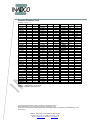
Appendix E: Parameters Densimeter ..................................................................................... 40
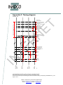
Appendix F: Timing diagram ................................................................................................... 41
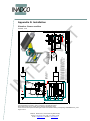
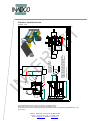
Appendix G: Installation .......................................................................................................... 42
Situation: Corner overflow .................................................................................... 42
Situation: Overflow In Line ................................................................................... 43
IN
TE
R
N
Appendix Z: Declaration of Incorporation ............................................................................... 44
Text printed Bold and in Italics, refer to functions on the Operator Panel.
Bold printed words refer to names used in drawings Appendix A and B.
Z:\Documenten\SG-bepaler\Handleiding\Docs\Docs actual\ENG\Installing and adjusting DENSIMETER v4_2.doc
Page 5 of 44
INADCO , Meerheide 18, 5521DZ Eersel (Netherlands)
Phone :++31 497 51 72 91 Fax :++31 497 51 74 69
E-mail : [email protected] Website : www.inadco.nl
Warning
Starting Up
ET
CAUTION: DANGER!!!!!!!!!!!
The Densimeter is a fully automated machine.
Because the machine is started remotely, it can be very dangerous for men and
machine to do checking on the machine
Always switch off the mains switch of the Mode Cabinet or the safety switch near the
motor, when working on, or checking the machine.
Welding
R
N
Whenever the mains voltage disappears, or a glitch in the voltage occurs, the
machine will always return in AUTO-mode.
It will start instantaneously, if the status of the start signal is high.
In most cases, data of already finished measurements will be lost. If a sticker has to
be printed, the printout will not show the correct data.
The weighing-signal and position-signal of the Densimeter are very sensitive. When
any welding is necessary nearby the Densimeter it is important to place the groundclamp nearby the place that needs to be welded.
It is not allowed to do any welding on the Densimeter.
When these precautions are not taken, the Densimeter can be damaged.
Mechanical overload
TE
When the weighing-section of the Densimeter is overloaded by a long time, or
severely overloaded a short time (impact) then the loadcell of the Densimeter will be
destroyed.
In normal use the Densimeter can be loaded until 40kg.
The weighing-section are the black cylinder, the bottom and the arm to open the
bottom.
Cable route
IN
When routing the cables, there must be taken some precautions with the sensitive
cables.
These cables need to be placed at least 20 cm away from “noise generating” power
cables or eventually placed in a steel housing.
Text printed Bold and in Italics, refer to functions on the Operator Panel.
Bold printed words refer to names used in drawings Appendix A and B.
Z:\Documenten\SG-bepaler\Handleiding\Docs\Docs actual\ENG\Installing and adjusting DENSIMETER v4_2.doc
Page 6 of 44
INADCO , Meerheide 18, 5521DZ Eersel (Netherlands)
Phone :++31 497 51 72 91 Fax :++31 497 51 74 69
E-mail : [email protected] Website : www.inadco.nl
ET
R
N
TE
IN
Empty page
Text printed Bold and in Italics, refer to functions on the Operator Panel.
Bold printed words refer to names used in drawings Appendix A and B.
Z:\Documenten\SG-bepaler\Handleiding\Docs\Docs actual\ENG\Installing and adjusting DENSIMETER v4_2.doc
Page 7 of 44
INADCO , Meerheide 18, 5521DZ Eersel (Netherlands)
Phone :++31 497 51 72 91 Fax :++31 497 51 74 69
E-mail : [email protected] Website : www.inadco.nl
Densimeter mounting configurations
De INADCO Densimeter is designed in such a way, that in can be mounted in almost every
situation that can occur.
ET
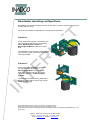
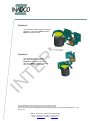
There are four possible configurations for mounting the Densimeter.
Situation 1
R
N
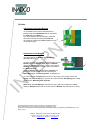
In this method the Cylinder is mounted on the
right hand side of the Motor, both mounting
bases, Mountingbase Cylinder en
Mountingbase Motor are placed on equal
level.
The backsides of both mounting-bases have to
be in the same plane, and the top of them at
exact equal height.
Situation 2
TE
In this method the Cylinder is mounted on
the right hand side of the Motor.
Mountingbase Motor is placed upside
down, with its lower side exactly 100mm
above the upper level of Mountingbase
Cylinder.
IN
The backsides of both mounting bases have
to be in the same plane, and the top of them
at exact equal height.
Text printed Bold and in Italics, refer to functions on the Operator Panel.
Bold printed words refer to names used in drawings Appendix A and B.
Z:\Documenten\SG-bepaler\Handleiding\Docs\Docs actual\ENG\Installing and adjusting DENSIMETER v4_2.doc
Page 8 of 44
INADCO , Meerheide 18, 5521DZ Eersel (Netherlands)
Phone :++31 497 51 72 91 Fax :++31 497 51 74 69
E-mail : [email protected] Website : www.inadco.nl
Situation 3
Situation 4
R
N
ET
This method is almost equal to Mounting
Situation 1. Only the Cylinder and the
Motor are both mirrored.
IN
TE
This method is almost equal to
Mounting Situation 2. Only the
Cylinder is now placed on the left
side of the Motor instead of the right
side, so they are both mirrored.
Text printed Bold and in Italics, refer to functions on the Operator Panel.
Bold printed words refer to names used in drawings Appendix A and B.
Z:\Documenten\SG-bepaler\Handleiding\Docs\Docs actual\ENG\Installing and adjusting DENSIMETER v4_2.doc
Page 9 of 44
INADCO , Meerheide 18, 5521DZ Eersel (Netherlands)
Phone :++31 497 51 72 91 Fax :++31 497 51 74 69
E-mail : [email protected] Website : www.inadco.nl
Mounting of the Densimeter
Densimeter in Emptying position
ET
As described above there are 4 ways of mounting the Densimeter.
But not only the relationship between the Mountingbase Cylinder and Mountingbase
Motor is important, there are some other relations to keep in mind. These relations will be
described down below.
One thing you must always keep in mind is that the Densimeter is mounted leveled.
R
N
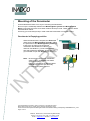
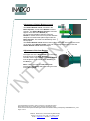
When the Densimeter is emptied, the Shovel will
rotate across the Mountingbase Cylinder. Hence
the space above this Mountingbase Cylinder has
to stay free. No parts of the supporting
construction are allowed to be there!! The
minimum free distance (c) has to be 180 mm.
Also space aside the Cylinder, at least 240 mm
(e) is needed to open the Bottom (see drawings).
c
e
IN
TE
Note: Be sure that when making shields for
safety or dust, the Bottom can still be
opened completely, so
that it can even touch the Mountingbase
Cylinder when (more than normally
necessary) completely opened.
Text printed Bold and in Italics, refer to functions on the Operator Panel.
Bold printed words refer to names used in drawings Appendix A and B.
Z:\Documenten\SG-bepaler\Handleiding\Docs\Docs actual\ENG\Installing and adjusting DENSIMETER v4_2.doc
Page 10 of 44
INADCO , Meerheide 18, 5521DZ Eersel (Netherlands)
Phone :++31 497 51 72 91 Fax :++31 497 51 74 69
E-mail : [email protected] Website : www.inadco.nl
Distance to Conveyor Belt
R
N
Overflow in corner
ET
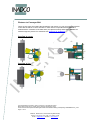
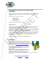
There are two ways of mounting the Densimeter near a belt. You can mount the Densimeter
in line with the belt or in corner overflow. In both cases it’s important that the Shovel is
leveled with the centerline of the belts drum (see pictures below) and that the Shovel can
rotate through the product. For measures see: appendix G: Installation
IN
TE
Overflow in line
Text printed Bold and in Italics, refer to functions on the Operator Panel.
Bold printed words refer to names used in drawings Appendix A and B.
Z:\Documenten\SG-bepaler\Handleiding\Docs\Docs actual\ENG\Installing and adjusting DENSIMETER v4_2.doc
Page 11 of 44
INADCO , Meerheide 18, 5521DZ Eersel (Netherlands)
Phone :++31 497 51 72 91 Fax :++31 497 51 74 69
E-mail : [email protected] Website : www.inadco.nl
Mechanical Adjustments
Now that the Densimeter is mounted on the right place and leveled we can adjust the
Densimeter.
Adjustment of the Shovel
ET
Motor
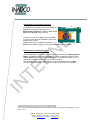
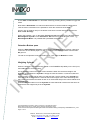
Place the Shovel in line with the motor by
using the Manual Motor-Axle.
Use the mounting-bolts of the motor for leveling
the Shovel in this situation.
g
f
R
N
When done use the Manual Motor-Axle to
place the Shovel square on the motor axle.
Now use again the mounting-bolts of the motor
for leveling the Shovel in this situation.
At last place the Shovel above the Cylinder and keep a gap of approx. 5mm (f)
between the Cylinder and the After scraper.
TE
Adjustment of the Prescraper
IN
When the Shovel is adjusted correctly we can
adjust the Prescraper.
Place the Prescraper so that there is a gap of
approx. 5mm (g) between the Shovel and the
Prescraper and that the Prescraper is leveled.
Text printed Bold and in Italics, refer to functions on the Operator Panel.
Bold printed words refer to names used in drawings Appendix A and B.
Z:\Documenten\SG-bepaler\Handleiding\Docs\Docs actual\ENG\Installing and adjusting DENSIMETER v4_2.doc
Page 12 of 44
INADCO , Meerheide 18, 5521DZ Eersel (Netherlands)
Phone :++31 497 51 72 91 Fax :++31 497 51 74 69
E-mail : [email protected] Website : www.inadco.nl
Adjustment of the Position Sensor
ET
The Disk must be placed so that when turning the
Shovel inner hexagonal the direction of
Mountingbase Cylinder the distance between the
Disk and the Sensor will be reduced.
R
N
Loosen the 2 bolts in the Disk and turn the Disk
so that the thickest site of the Disk is in the same
position as the picture.
Tighten the 2 bolts in the Disk and place the
Sensor so that there is a gap of 1mm between the Disk and the Sensor.
Adjustment of the Position Disk
IN
TE
When the Shovel is in the ultimate position (the bottom touches the Mounting base
Motor), the Disk must manually be rotated so that on the Operator Panel on Pic 10
at Actual Pos Arm shows a value close to 3500. This equals the voltage of 1.45 V
measured between terminal 2 and 3 in the control cabinet.
Now the Disk can be fixed in place with the 2 inner hexagonal bolts in the Disk.
The centerline of the Disk is on the same level as the centerline of the Sensor.
Text printed Bold and in Italics, refer to functions on the Operator Panel.
Bold printed words refer to names used in drawings Appendix A and B.
Z:\Documenten\SG-bepaler\Handleiding\Docs\Docs actual\ENG\Installing and adjusting DENSIMETER v4_2.doc
Page 13 of 44
INADCO , Meerheide 18, 5521DZ Eersel (Netherlands)
Phone :++31 497 51 72 91 Fax :++31 497 51 74 69
E-mail : [email protected] Website : www.inadco.nl
Cylinder
Adjustment of the Axle Bottom
ET
To get reliable and correct measurements it’s
important that the Axle Bottom will be centered in
the Chimney of the Roof (h).
You can accomplice this by using the oversized
9mm holes used for mounting the Load cell.
The holes for mounting the Roof (4xM8 mm) may
not be made larger.
R
N
h
Adjustment of the Bottom
The gap between the Bottom and Cylinder is
approximately 2mm (i).
TE
To make sure that the Cylinder is closed totally by the
Bottom adjust the Striking bolt, while the Bottom
closes the Cylinder completely, until the head off the
Striking bolt touches the rubber cushion mounted on
the Block Bearing.
When the Bottom isn’t equal with the Cylinder use
the 2 M12 mounting bolts, used for mounting the
Block Bearing on the Block Cylinder, for adjustment.
IN
To make sure that the Bottom will close nice and easy you must pre-tension the
Spring with the Arm Spring. In general this means that the Arm Spring will be fixed
parallel to the Mounting base Cylinder.
Note: When the Arm Spring is mounted too high it will bounce against the Roof
when the Bottom will be opened. In that case the Bottom can’t be opened correctly.
Text printed Bold and in Italics, refer to functions on the Operator Panel.
Bold printed words refer to names used in drawings Appendix A and B.
Z:\Documenten\SG-bepaler\Handleiding\Docs\Docs actual\ENG\Installing and adjusting DENSIMETER v4_2.doc
Page 14 of 44
INADCO , Meerheide 18, 5521DZ Eersel (Netherlands)
Phone :++31 497 51 72 91 Fax :++31 497 51 74 69
E-mail : [email protected] Website : www.inadco.nl
i
Adjustment of Switch Bottom-closed
R
N
ET
The Switch Bottom closed, mounted in the
Block Cylinder, checks if the Bottom is closed
properly. The Switch Bottom Closed is mounted
approx. 2mm above the Bottom (i2).
For a good and reliable measuring when the
Bottom is closed, there is an iron (so NO stainless
steel) M6 countersink bolt placed right under the
i2
Block Cylinder. The other hole definitively must
be kept open.
The Switch Bottom closed will be locked in place with a M6 inner hexagonal screw
on the back of the Block Cylinder. This bolt must be tightened lightly or else the
Switch Bottom closed will be damaged
j
Adjustment of the Arm Bottom
k
The upper side of the Arm Bottom is on the same
level as the top of the Axle Bottom (j)
The side close to the Cylinder of the Arm Bottom
must be placed in the middle of the Chimney on
the Roof (k).
IN
TE
Note: Take notice that the Take along bolt
touches the Springstrip without touching the bolts
on the Springstrip.
Text printed Bold and in Italics, refer to functions on the Operator Panel.
Bold printed words refer to names used in drawings Appendix A and B.
Z:\Documenten\SG-bepaler\Handleiding\Docs\Docs actual\ENG\Installing and adjusting DENSIMETER v4_2.doc
Page 15 of 44
INADCO , Meerheide 18, 5521DZ Eersel (Netherlands)
Phone :++31 497 51 72 91 Fax :++31 497 51 74 69
E-mail : [email protected] Website : www.inadco.nl
Checking of the electrical connections after
installation.
The Densimeter in general will be delivered completely adjusted. Therefore it is possible to
do a quick check on the connections after the Densimeter is put in place and al connections
are made.
-
Analogue input
Movement motor
Detection bottom open
Weighing Cylinder
ET
There are 4 signals that need to be checked.
R
N
All these checks can be done using the Operator Panel.
Analogue input
To determine if the analogue input is connected in the right way, switch the Operator Panel
to screen Pic10 (settings arm) by pressing the following buttons starting from the main
screen, F2/fill -> F3/set -> F1/arm.
Now press once on the button arrow down. On the top of the screen is now the text Actual
pos. Arm, with a value between 0 and 4095 at the end of the line. (For a full explanation of
the Operator Panel look at the manual OP panel DENSIMETER)
TE
By moving the Arm by using the Manual Control Motor Axle the value behind Actual pos.
arm will change. When the Arm moves in the direction to the Cylinder the value should
increase. Moving the Arm in the direction to the Loading Position the value should
decrease.
Is the value 4095 then there is no signal on the Analogue input.
IN
Movement Arm
Move the Arm in the position as shown in picture on the side by
using the Manual Control Motor Axle. (Or mirrored when used an
other mounting setup). The value behind Actual pos. arm will now
be 1600 which stands for 6,10 V dc measured on terminal 2 and 3
in the control cabinet (See appendix C: Connection diagram).
To determine the right electrical movements by the Arm you must
place the Densimeter in manual mode.
Press from the main screen on the OP the following buttons:
F2/fill -> F1/m/a.
On the end of the 3rd line is shown the actual mode of the
Densimeter. If shown Man the Densimeter is in manual mode, if
Text printed Bold and in Italics, refer to functions on the Operator Panel.
Bold printed words refer to names used in drawings Appendix A and B.
Z:\Documenten\SG-bepaler\Handleiding\Docs\Docs actual\ENG\Installing and adjusting DENSIMETER v4_2.doc
Page 16 of 44
INADCO , Meerheide 18, 5521DZ Eersel (Netherlands)
Phone :++31 497 51 72 91 Fax :++31 497 51 74 69
E-mail : [email protected] Website : www.inadco.nl
shown Auto the Densimeter is in automatic mode. By pressing F1 it is possible to toggle the
mode.
Now that the Densimeter is in manual mode and there is checked that the safety switch
near the motor is switched on it is possible to check the movement of the Arm.
ET
Press in Pic 10 (settings Arm) on the button arrow down until the last line shows the text:
Unlo Load Go Copy.
When now pressed 1 sec. on the button F1/Unlo the Arm must move in the direction of the
Mountingbase Cylinder. Press F2/Load the Arm must move in the direction of the
Mountingbase Motor. It is possible that a password will be asked.
Detection Bottom open
R
N
When the Switch Bottom closed is connected and the Bottom will be opened, a led lamp
on the PLC in the cabinet (input I1.4) will go out and on the Operator Panel a led at button
K2 goes on.
The led on the Operator Panel will remain on for 2 sec. after the Bottom is closed.
Weighing Cylinder
TE
When the loadcell is connected and a red led on the SIWAREX M (halfway on the PLC) is lit,
the Load cell isn’t connected well.
IN
On the Operator Panel in the main screen behind the letter C is the actual weight in the
Cylinder viewed. When the Cylinder is empty the value is between –0,500 and 0,500 and
doesn’t change.
When a known weight, heavier than 5 kg and less than 10 kg is placed in the Cylinder the
value behind C must increase the same as the known weight. Is the value decreasing then
the 2 wires connected to terminals 12 and 13 on the terminal strip in the control cabinet must
be exchanged.
When the weight is taken out of the Cylinder the value behind C must become the same as
it was before the weight was put in the Cylinder.
Text printed Bold and in Italics, refer to functions on the Operator Panel.
Bold printed words refer to names used in drawings Appendix A and B.
Z:\Documenten\SG-bepaler\Handleiding\Docs\Docs actual\ENG\Installing and adjusting DENSIMETER v4_2.doc
Page 17 of 44
INADCO , Meerheide 18, 5521DZ Eersel (Netherlands)
Phone :++31 497 51 72 91 Fax :++31 497 51 74 69
E-mail : [email protected] Website : www.inadco.nl
Electrical Adjustments
After the Mechanical adjustments of the Densimeter are finished and all connections are
checked, it’s time to do the Electrical adjustment.
Settings Frequency Converter
Settings Positions arm Shovel
Settings Cylinder
Settings Time
Settings Signals
Settings Communication
ET
There are 6 types of settings.
When all the parameters are filled in and the Densimeter works as desired, it’s possible to
save all parameters for back up.
R
N
From the main screen press the following buttons:
F3/data -> F4/ saved set.
TE
Now press F1/save for saving all parameters.
When you press F2/rest all parameters will be restored as the saved parameters.
Press F3/view para for viewing the saved parameters
Settings of the Frequency Converter
IN
Before we can adjust the Densimeter all cables must be connected and the frequency
converter must have the right parameters.
For the parameters of the frequency converter look at appendix D: Parameters Frequency
converter.
Text printed Bold and in Italics, refer to functions on the Operator Panel.
Bold printed words refer to names used in drawings Appendix A and B.
Z:\Documenten\SG-bepaler\Handleiding\Docs\Docs actual\ENG\Installing and adjusting DENSIMETER v4_2.doc
Page 18 of 44
INADCO , Meerheide 18, 5521DZ Eersel (Netherlands)
Phone :++31 497 51 72 91 Fax :++31 497 51 74 69
E-mail : [email protected] Website : www.inadco.nl
Settings Positions Arm
For a good and reliable working Densimeter there are some important positions
necessary.
These positions will be determined when the Densimeter is in the manual mode.
Changing the positions is possible in manual as well automatic mode.
ET
Press from the main screen the following buttons:
F2/fill -> F1/m/a.
On the end of the 3rd line you see the actual mode of the Densimeter. If shown Man
the Densimeter is in manual mode, if shown Auto the Densimeter is in automatic
mode. By pressing F1 it is possible for switching the operation mode.
When the Densimeter is put in the manual mode a led on button K1 will go flashing.
R
N
After all parameters are set press in the screen MAN/AUTO on the button F2/cycle.
The Densimeter will then make 1 full strike.
Now that the Densimeter is put in the manual mode we go back 1 screen by
pushing the ESC-Button. We go to the Pic 10 (settings Arm) by pressing the buttons
F3/set -> F1/arm.
Use the arrow keys up and down for scrolling between the parameters.
The value on which the cursor is blinking can be changed.
For moving the Arm in the direction of the Mountingbase Cylinder, press F1/Unlo.
For moving the Arm in the direction of the Mountingbase Motor, press F2/Load.
TE
With the button F3/go it’s possible to send the Arm to the position where the cursor
is blinking, unless the position is already reached or passed.
IN
Note:
- Take notice that the Arm is a fast moving object. Therefore it is important that
you don’t press the buttons to rotate too long. If you do there is a chance of
mechanical jamming.
If the Densimeter will be become jammed you can release it by using the
Manual Control Motor Axle. When you don’t have a Manual Control Motor
Axle un-tighten the Arm Bottom and use the button F2/Load for moving the
Arm back in position. When re-tighten the Arm Bottom make sure that this is
done the right way (see Adjustment Arm Bottom)
-
Some positions will react differently when the Arm is loaded with heavy soil. It is
therefore possible that the value for these positions must slightly be changed.
The positions Reversal Pos, Stop unloading Pos and Loading Pos are the
positions that react different and are allowed for changing while the Densimeter
is in automatic mode.
Text printed Bold and in Italics, refer to functions on the Operator Panel.
Bold printed words refer to names used in drawings Appendix A and B.
Z:\Documenten\SG-bepaler\Handleiding\Docs\Docs actual\ENG\Installing and adjusting DENSIMETER v4_2.doc
Page 19 of 44
INADCO , Meerheide 18, 5521DZ Eersel (Netherlands)
Phone :++31 497 51 72 91 Fax :++31 497 51 74 69
E-mail : [email protected] Website : www.inadco.nl
The * underneath each described parameter down below have the meaning:
*
**
***
Free to change
Not allowed to change
Only allowed to change with permission of INADCO
Limit Unloading Position
ET
**
Position Limit Unloading Position is the position
so that the Bottom cannot be opened further
(mechanical end, Bottom touches the
Mountingbase Cylinder.
When the value is too high the Densimeter can
become jammed.
R
N
Manually place the Densimeter in this position
and make sure that the cursor blinks behind the
text Limit Unloading.
Now press F4/copy or type over the value as shown behind Actual Pos. Arm and
confirm by pressing Enter.
Margin is the value 4095 minus the value of Limit Unloading. This value must be
typed in by hand and also confirmed by pressing the Enter-button.
Limit Loading Position
TE
**
Position Limit Loading Position is the position
just before the Arm in Loading Position is
mechanical jammed.
When the value is too low the Densimeter can
become jammed.
IN
Manually place the Densimeter in this position
and make sure that the cursor blinks behind the
text Limit Loading P.
Now press F4/copy or type over the value as
shown behind Actual Pos. Arm and confirm by pressing Enter.
Margin is the value at Limit Loading P + 50. Confirm by pressing Enter.
Text printed Bold and in Italics, refer to functions on the Operator Panel.
Bold printed words refer to names used in drawings Appendix A and B.
Z:\Documenten\SG-bepaler\Handleiding\Docs\Docs actual\ENG\Installing and adjusting DENSIMETER v4_2.doc
Page 20 of 44
INADCO , Meerheide 18, 5521DZ Eersel (Netherlands)
Phone :++31 497 51 72 91 Fax :++31 497 51 74 69
E-mail : [email protected] Website : www.inadco.nl
Loading Position
ET
*
The Loading Position is the position where the
Shovel will be filled with the product to measure.
It’s important that the Shovel rotates far enough
through the product flow when your product is
inhomogeneous.
Manually place the Shovel in the product flow
and make sure that the cursor blinks behind the
text Loading Pos.
Take the value as shown behind Actual Pos. Arm and add 200 to it. Type the new
value and confirm by pressing Enter.
R
N
When during production it turns out that the Shovel isn’t rotating enough through the
product flow decrease the value in steps of 50.
Margin is the value at Limit Pos + 100. Confirm by pressing Enter.
Reversal Position
TE
***
The Reversal Position is the position where the
Shovel starts to decelerate before switching the
moving direction.
To determine this position you must first set the
CheckIncrease Pos. (See next page)
When the Check Increase Pos is set decrease the value with 175 and type the
value at Reversal Pos. Confirm by pressing Enter.
IN
When it turns out that the Shovel touches the Arm Bottom decrease the value in
steps of 10 so that the point of reversal the Shovel the After scraper is between the
Cylinder and the Arm Bottom.
(When changing this position you must usually also change the Check Increase
Pos.)
Margin is always 1000.
Text printed Bold and in Italics, refer to functions on the Operator Panel.
Bold printed words refer to names used in drawings Appendix A and B.
Z:\Documenten\SG-bepaler\Handleiding\Docs\Docs actual\ENG\Installing and adjusting DENSIMETER v4_2.doc
Page 21 of 44
INADCO , Meerheide 18, 5521DZ Eersel (Netherlands)
Phone :++31 497 51 72 91 Fax :++31 497 51 74 69
E-mail : [email protected] Website : www.inadco.nl
CheckIncrease Position
***
The CheckIncrease Position is the position
where there will be checked how much the weight
in the Cylinder has increased when the Shovel
has put the product in the Cylinder.
R
N
Margin is always 1000.
ET
To determine this position place the Shovel so
that the After Scraper is just above the edge of
the Cylinder.
Make sure that the cursor blinks behind the text
CheckIncr Pos. Now press F4/copy or type over
the value as shown behind Actual Pos. Arm and confirm by pressing Enter.
CheckFull Position
***
The Check Full Position is the position where
there will be checked how much weight in the
Cylinder has increased after scraping of the
Cylinder.
TE
To determine this position place the Shovel in
place so that the After Scraper is just in front of
the Cylinder. (see Pic)
Make sure that the cursor blinks behind the text
Check Full Pos. Now press F4/copy or type over the value as shown behind Actual
Pos. Arm and confirm by pressing Enter.
IN
Margin is always 200.
Text printed Bold and in Italics, refer to functions on the Operator Panel.
Bold printed words refer to names used in drawings Appendix A and B.
Z:\Documenten\SG-bepaler\Handleiding\Docs\Docs actual\ENG\Installing and adjusting DENSIMETER v4_2.doc
Page 22 of 44
INADCO , Meerheide 18, 5521DZ Eersel (Netherlands)
Phone :++31 497 51 72 91 Fax :++31 497 51 74 69
E-mail : [email protected] Website : www.inadco.nl
Stop Unloading Position
***
The Stop Unloading Position is the position
where the Shovel starts to decelerate before
switching the direction of the motion after the
Bottom has been opened.
ET
To determine this position take the value of
CheckIncrease Position en increase this value
with 400.Type the new value in behind Stop
Unload Pos. Confirm by pressing Enter.
R
N
When it turns out that the Bottom will not be opened completely check for
mechanical errors. If there are no mechanical errors increase the value with steps of
50 until the Bottom will be opened completely.
If the Bottom bounces against the Mountingbase Cylinder decrease the value in
steps of 50.
Note: It’s possible that the value must be changed when the Cylinder is fully loaded
with heavy or sticky soil, because this has more friction.
Margin is the value 4095 minus the value of the Stop Unloading Position. Confirm
by pressing Enter.
Leakagedetection Position
TE
***
The Leakage detection Position is the position
where there will be checked how much weight is
leaking from the Cylinder after scraping of the
Cylinder, and if the Bottom is closed.
IN
Make sure that the cursor blinks behind the text
Leak detection.
Take the value as shown behind CheckFull Pos.
and decrease with 100. Type the new value and
confirm by pressing Enter.
Margin is always 200.
Start Unloading Position
***
The Start Unloading Position is the position
where the Cylinder starts to been opened.
The value that must be entered here can be read
in the field Position switch in the flow. Confirm
by pressing Enter.
Text printed Bold and in Italics, refer to functions on the Operator Panel.
Bold printed words refer to names used in drawings Appendix A and B.
Z:\Documenten\SG-bepaler\Handleiding\Docs\Docs actual\ENG\Installing and adjusting DENSIMETER v4_2.doc
Page 23 of 44
INADCO , Meerheide 18, 5521DZ Eersel (Netherlands)
Phone :++31 497 51 72 91 Fax :++31 497 51 74 69
E-mail : [email protected] Website : www.inadco.nl
ET
R
N
TE
IN
Text printed Bold and in Italics, refer to functions on the Operator Panel.
Bold printed words refer to names used in drawings Appendix A and B.
Z:\Documenten\SG-bepaler\Handleiding\Docs\Docs actual\ENG\Installing and adjusting DENSIMETER v4_2.doc
Page 24 of 44
INADCO , Meerheide 18, 5521DZ Eersel (Netherlands)
Phone :++31 497 51 72 91 Fax :++31 497 51 74 69
E-mail : [email protected] Website : www.inadco.nl
Settings Cylinder
Filling Minimal Increase
ET
For setting up the parameters for the Cylinder go to the Pic 11(settings Cylinder) by
Pressing the following buttons starting from the main screen.
F2/fill -> F3/set -> F2/cyl. Use the arrow keys up and down for scrolling between the
parameters.
***
Default value = 0,25 (setting)
Sets the minimum weight increment in the Cylinder for getting a valid measurement.
Used for getting a full detection.
Full Counter
R
N
**
Default value = 2 (fixed value)
Sets a value on how many times the Densimeter must have a full detection before
the Cylinder will be emptied.
Material detection
***
Default value = 0,35 kg (setting)
Sets the minimum weight increment in the Cylinder for getting a valid measurement.
Used for getting fill detection.
Slip detection arm
**
Default value = 10 (fixed value)
TE
Accretion detection
***
Default value Warning = 0,5 kg (setting)
Default value Blockage = 0,99 kg (setting)
Sets a weight when the Densimeter will generate an alarm if the Densimeter is not
completely empty when it should be. At Warning only a message will be generated,
but the Densimeter keeps on running. At Blockage the Densimeter will also stop
measuring, and switch to manual mode.
IN
Retries
**
Default value = 3 (fixed value)
Leakage detection
**
Default value = 0,5 kg (fixed value)
Volume Cyl
**
Default value = 20 L (read Only)
Empty page
Text printed Bold and in Italics, refer to functions on the Operator Panel.
Bold printed words refer to names used in drawings Appendix A and B.
Z:\Documenten\SG-bepaler\Handleiding\Docs\Docs actual\ENG\Installing and adjusting DENSIMETER v4_2.doc
Page 25 of 44
INADCO , Meerheide 18, 5521DZ Eersel (Netherlands)
Phone :++31 497 51 72 91 Fax :++31 497 51 74 69
E-mail : [email protected] Website : www.inadco.nl
Settings Delays
Unloading Cylinder
ET
For setting up the delay parameters for the Densimeter go to the Pic 17(settings
timers) by pressing the following buttons starting from the main screen.
F2/fill -> F3/set -> F3/time.
Use the arrow keys up and down for scrolling between the parameters.
***
Default value = 2 sec.
Sets the time necessary by the Densimeter for getting completely empty.
Closing Cylinder
***
Default value = 2 sec.
Sets the time necessary by the Densimeter for letting stay the Cylinder opened.
R
N
Start-delay
*
Default value = 2 sec.
Sets the time used for a delay of starting the Densimeter between getting the startsignal en actual starting measuring.
Stop-delay
*
Default value = 2 sec.
Sets the time used for letting the Densimeter measure even after the start-signal
was removed.
TE
Pause-delay
*
Default value = 0 sec.
Sets the time used for get a delay to place the Densimeter in pause. The sample
taking will stop. Only applied when terminal 8 (= I1.3) is connected in the cabinet.
(See appendix C: Connection Diagram)
Restart-delay
IN
*
Default value = 0 sec
Sets the time used for get a delay between removing Pause-signal and let the
Densimeter measure again. Only applied when terminal 8 (= I1.3) is connected in
the cabinet. (See appendix C: Connection Diagram)
Running Delay
*
Default value = not used
Refresh Comm.
**
Default value = 1 +0,5 sec
Sets the time used for refreshing data getting from a weighing belt or weighing
bridge.
Text printed Bold and in Italics, refer to functions on the Operator Panel.
Bold printed words refer to names used in drawings Appendix A and B.
Z:\Documenten\SG-bepaler\Handleiding\Docs\Docs actual\ENG\Installing and adjusting DENSIMETER v4_2.doc
Page 26 of 44
INADCO , Meerheide 18, 5521DZ Eersel (Netherlands)
Phone :++31 497 51 72 91 Fax :++31 497 51 74 69
E-mail : [email protected] Website : www.inadco.nl
Motion Cyl PLC
**
Default value = 0,6 (fixed value)
Motion Cyl Siwarex
Default value = (read only)
IN
TE
R
N
ET
**
Text printed Bold and in Italics, refer to functions on the Operator Panel.
Bold printed words refer to names used in drawings Appendix A and B.
Z:\Documenten\SG-bepaler\Handleiding\Docs\Docs actual\ENG\Installing and adjusting DENSIMETER v4_2.doc
Page 27 of 44
INADCO , Meerheide 18, 5521DZ Eersel (Netherlands)
Phone :++31 497 51 72 91 Fax :++31 497 51 74 69
E-mail : [email protected] Website : www.inadco.nl
Settings Signals
Input Vav Cyl
**
Default value = 1 (fixed value)
Input Spike Cyl
**
Default value = 1 (fixed value)
Filter AI-Cyl
Default value = 2 (fixed value)
R
N
**
ET
For setting up the signal parameters for the Densimeter go to the Pic 16(settings
Analogue input) by pressing the following buttons starting from the main screen.
F2/fill -> F3/set -> F4/sign.
Use the arrow keys up and down for scrolling between the parameters.
Input Vav arm
**
Default value = 1 (fixed value)
Input Spike arm
**
Default value = 1 (fixed value)
Motion range Cyl PLC
Default value = 0,4 (fixed value)
TE
**
Settings Communication
IN
For setting up the communication for the Densimeter go to the Pic
22(Communication) by pressing the following buttons starting from the main screen.
F3/data -> F1/com.
Use F1/com in for setting in incoming communication.
Use F2/com out for setting in outgoing communication.
Incoming (Cin)
**
Default value = Off
The state of this parameter depends on if there is communication necessary
between a weighing belt or a weighing bridge. Use F3/com on for putting the
communication ON and use F4/com off for putting the communication OFF.
Outgoing (Cout)
**
Default value = Off
The state of this parameter depends on if there is outgoing communication
necessary between for e.g. a computer or a printer. Use F3/com on for putting the
communication ON and use F4/com off for putting the communication OFF.
Text printed Bold and in Italics, refer to functions on the Operator Panel.
Bold printed words refer to names used in drawings Appendix A and B.
Z:\Documenten\SG-bepaler\Handleiding\Docs\Docs actual\ENG\Installing and adjusting DENSIMETER v4_2.doc
Page 28 of 44
INADCO , Meerheide 18, 5521DZ Eersel (Netherlands)
Phone :++31 497 51 72 91 Fax :++31 497 51 74 69
E-mail : [email protected] Website : www.inadco.nl
Calibrating the Densimeter
ET
When using the Densimeter for the first time it needs to be calibrated.
Go to the screen Calibrating (Pic 19) by pressing in the main screen on F1/cal.
Behind the text Cylinder stands the actual weight in the Cylinder at that moment.
When this value isn’t 0,000 kg press F1/zero for tare the Cylinder after you made
sure that the Cylinder is empty and clean.
Next press on the button F2/cal to go to the calibration screen.
R
N
On the first line you see the actual weight of the Densimeter.
On the second line you type the weight which you are using for the calibration. This
weight must be between 5kg and 10 kg.
When the Cylinder is empty and clean and the actual weight is 0,000 kg press on
the button F1/empty.
Wait for 20 seconds and put the calibration weight in the Cylinder.
Now press on the button F2/cal. The Operator Panel will go to the main screen
where you can see behind C the weight of your calibration weight. When you take
the calibration weight out of the Cylinder the value weight will become approx. zero.
Place and take out the calibration weight a few times from the Cylinder for checking
consistency of weighing.
TE
When there is a different weight every time you place and take out the calibration
weight from the Cylinder there is somewhere mechanical jamming between the
weighing parts of the Densimeter and the fixed parts of the Densimeter.
IN
After the calibration en zeroing the actual weight of an empty Densimeter is
between –0,005 kg and 0,005 kg.
Periodically Checking The Densimeter
Although the Densimeter doesn’t need much attention it’s still recommended to do a
once per week checking to keep good en reliable measurements and results.
To do this make the Densimeter clean and check if the weighing works correct by
Putting an object for which you know the weight into the Cylinder and check if the
actual weight of the Cylinder is increased as much as the weight you used. When
you remove the object the actual weight must be the same as before.
It’s possible that the actual weight is slightly changed.
Text printed Bold and in Italics, refer to functions on the Operator Panel.
Bold printed words refer to names used in drawings Appendix A and B.
Z:\Documenten\SG-bepaler\Handleiding\Docs\Docs actual\ENG\Installing and adjusting DENSIMETER v4_2.doc
Page 29 of 44
INADCO , Meerheide 18, 5521DZ Eersel (Netherlands)
Phone :++31 497 51 72 91 Fax :++31 497 51 74 69
E-mail : [email protected] Website : www.inadco.nl
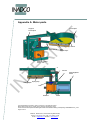
Appendix A: Motor-parts
Prescraper
ET
Support
Prescraper
Shovel
Strip
Afterscraper
R
N
Arm Shovel
IN
TE
Manual Control
Motor Axle
Afterscraper
A
Sensor
Mountingbase
Motor
Springstrip
Disk
Gearbox
Motor
Text printed Bold and in Italics, refer to functions on the Operator Panel.
Bold printed words refer to names used in drawings Appendix A and B.
Z:\Documenten\SG-bepaler\Handleiding\Docs\Docs actual\ENG\Installing and adjusting DENSIMETER v4_2.doc
Page 30 of 44
INADCO , Meerheide 18, 5521DZ Eersel (Netherlands)
Phone :++31 497 51 72 91 Fax :++31 497 51 74 69
E-mail : [email protected] Website : www.inadco.nl
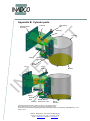
Appendix B: Cylinder-parts
Take Along
bolt
Loadcell
Mountingbase
Cylinder
ET
Chimney
R
N
Cylinder
Spring
Axle
Bottom
Arm
Bottom
IN
TE
Roof
Block
Bearing
s
Bottom
Arm
Spring
Striking
Bolt
Switch Bottom
Bearing closed (not visible)
Block
Cylinder
Text printed Bold and in Italics, refer to functions on the Operator Panel.
Bold printed words refer to names used in drawings Appendix A and B.
Z:\Documenten\SG-bepaler\Handleiding\Docs\Docs actual\ENG\Installing and adjusting DENSIMETER v4_2.doc
Page 31 of 44
INADCO , Meerheide 18, 5521DZ Eersel (Netherlands)
Phone :++31 497 51 72 91 Fax :++31 497 51 74 69
E-mail : [email protected] Website : www.inadco.nl
bk
2
2x0,5
1
Nr. 10005
yg
yg
bn
gy
EMC-cable
bk
Nr. 10003
bn
bn
yg
gy
bn
bk
additional Earth-wire Ø6 mm²
INADCO , Meerheide 18, 5521DZ Eersel (Netherlands)
Phone :++31 497 51 72 91 Fax :++31 497 51 74 69
E-mail : [email protected] Website : www.inadco.nl
Position
Arm
3 4
bk
bu
wh
bn
2
bk
bu
bn
Bottom
Closed
Warning
Alarm
R
N
bk
rd
wh
gn
bn or gy
bu
2
1
Loadcell
Cylinder
1 3
10 11 12 13 14 15 16 1
6 10 11 12 13 14 15 16
gn
1
3
Release
(optional)
Control Cabinet
1 4
2
4
Safetyfe
(optional)
3
1 2
2
3
Term
10
11
12
13
14
15
16
Term
1
2
3
4
1
2
5
6
Nr.
10
11
12
13
14
15
16
Nr.
1a
2a
3
4
1c
2c
5
6
Color
brown
brown/white
blue
blue/white
green
green/white
inner shielding
Wires inner ring
Color
brown
white
green
blue
red
black
orange
yellow
shielding outside on
earth terminal in the cabinet
Wires outer ring
Connection with supplied white
cable with 16 wires nr. 00610
1 2 3 4
ET
4
Existing
control cabinet
3 4
1
9 10 11 12 13 14 15 16 17 18 19 20 21 22 23 24 25 26 27 28 29 30 31
6 10 11 12 13 14 15 16
bn or gy
PTC
(optioneel)
5
4
3
2
2
bu
1
bu
service
(optional)
5
4
bk
bk
wh
bu
1
4
7
rd
Connection diagram Densimeter
be
bk
bn - W1
bk - V1
gy - U1
L
Nr. 00610
wh
bn - U1
bk - V1
gy - W1
N
Nr. 30210
Connect on
M8-bolt of
the loadcell
24Vdc
Nr. 02207
Connection motor
24Vdc
junctionbox
KLK1
24Vdc
6
8
start NO
Nr. 31209
motor connected in
0Vdc
5
pause
1a 1c 2a 2c 3
4
Position Arm
2c 3
6
Operator Panel
external
5
sense +
240Vac
min 6A / max 16A
nutral line grounded
4
0Vdc
bottom closed
3
sign+
2
sense-
1c 2a
2
exc+
1 1a
0Vdc
2
sign-
1
exc-
1
S11
PE 1
X3
shield
2
S12
PE 1
Safety circuit
pilz
S21
2
Loadcell
S22
1
X1
Power supply
TE
Programmable Logic Controller
SIEMENS
Data
V W PE
X2
24Vdc
circuit
breaker
GND
U
SIEMENS
Freq.-convertor
Freq.
converter
circuit
breaker
communication.
(optional)
safety switch
near motor
mounting
plate
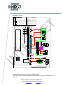
V4.2.16
IN
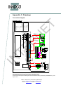
Appendix C: Drawings
Connection diagram
Standard v4.2.16
sh
Text printed Bold and in Italics, refer to functions on the Operator Panel.
Bold printed words refer to names used in drawings Appendix A and B.
Z:\Documenten\SG-bepaler\Handleiding\Docs\Docs actual\ENG\Installing and adjusting DENSIMETER v4_2.doc
Page 32 of 44
2x0,5
1
Nr. 10005
pe
bn
gy
EMC-cable
bk
Nr. 10003
1
1
bk
bu
wh
bn
pe
gy
bn
bk
additional Earth-wire Ø6 mm²
INADCO , Meerheide 18, 5521DZ Eersel (Netherlands)
Phone :++31 497 51 72 91 Fax :++31 497 51 74 69
E-mail : [email protected] Website : www.inadco.nl
Position
Arm
3 4
bk
bu
bn
Bottom
Closed
4
2
5
service
(optional)
1
Release
(optional)
Warning
Alarm
Control Cabinet
bk
rd
wh
gn
bn or gy
bu
2
1
Loadcell
Cylinder
1 3
1a 1b 2a 2b 3a 3b 16 1
(optional)
1 4
2
4
Safetyfe
2
1 2
3
4
1 2 3 4
Existing
control cabinet
3 4
1
1
2
5
6
32
33
34
35
36
37
38
39 11a
40 13a
9a
9b
8a
8b
12a
12b
10a
10b
11a
11b
green/white
green/brown
white/black
white/grey
brown/grey
white/yellow
brown/yellow
white/red
brown/red
white/pink
brown/pink
white/blue
brown/blue
shieling on earth-terminal
in the cabinet
pairs outer ring
7a
pairs inner ring
Term Nr. Color
1 5a black
2 4a blue
3 4b red
1 5b purple
2 6a grey/pink
4 6b red/blue
10 1a white
11 1b brown
12 2a green
13 2b yellow
14 3a grey
15 3b pink
16 16 shield inner pairs
Connection with grey double shielded
supplied cable according to DIN4700
cablenumber 00610
ET
(optional)
3
9 10 11 12 13 14 15 16 17 18 19 20 21 22 23 24 25 26 27 28 29 30 31
6 10 11 12 13 14 15 16
bu
2
3
2
2
gn
PTC
(optioneel)
6
bn or gy
1
R
N
5
rd
Connection diagram Densimeter
2
wh
bn - W1
bk - V1
gy - U1
pe
bk
bn - U1
bk - V1
gy - W1
2
1
Nr. 30210
Connect on
M8-bolt of
the loadcell
L
Nr. 02207
Connection motor
N
Nr. 00610
5a 5b 4a 6a 4b 6b 9a 9b 8a 8b 1a 1b 2a 2b 3a 3b 16
24Vdc
Nr. 31209
motor connected in
2
0Vdc
240Vac
min 6A / max 16A
nutral line grounded
0Vdc
2
sign+
2
4
24Vdc
1 5a 9a 5b 4a 9b 6a 4b 6b 8a 8b 3
24Vdc
1
sense-
safety switch
near motor
mounting
plate
0Vdc
8
4
Position Arm
start NO
7
bottom closed
3
Operator Panel
external
pause
1
sense +
PE 1
X3
exc+
2
sign-
PE 1
X1
exc-
2
Safety circuit
pilz
S11
1
X2
Loadcell
S12
V W PE
Power supply
Programmable Logic Controller
SIEMENS
TE
24Vdc
circuit
breaker
shield
U
SIEMENS
Freq.-convertor
Freq.
converter
circuit
breaker
S21
bn
S22
bn
Data
bu
GND
bk
communication.
(optional)
bu
wh
bk
V4.2.25
IN
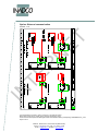
Standard v4.2.25
sh
junctionbox
KLK1
Text printed Bold and in Italics, refer to functions on the Operator Panel.
Bold printed words refer to names used in drawings Appendix A and B.
Z:\Documenten\SG-bepaler\Handleiding\Docs\Docs actual\ENG\Installing and adjusting DENSIMETER v4_2.doc
Page 33 of 44
Option: External communication
IN
TE
R
N
ET
Version: v1.0
Text printed Bold and in Italics, refer to functions on the Operator Panel.
Bold printed words refer to names used in drawings Appendix A and B.
Z:\Documenten\SG-bepaler\Handleiding\Docs\Docs actual\ENG\Installing and adjusting DENSIMETER v4_2.doc
Page 34 of 44
INADCO , Meerheide 18, 5521DZ Eersel (Netherlands)
Phone :++31 497 51 72 91 Fax :++31 497 51 74 69
E-mail : [email protected] Website : www.inadco.nl
Moisture
IR-sensor
32 33 34 35 36 37 38 39 40
X3
10a
12b
12a
Nr. 00610
13a
13a
7b
7b
7a
7a
11b
11b
11a
11a
10b
10b
10a
12b
12a
gn
we
bn
yw
rd
INADCO , Meerheide 18, 5521DZ Eersel (Netherlands)
Phone :++31 497 51 72 91 Fax :++31 497 51 74 69
E-mail : [email protected] Website : www.inadco.nl
IR t/c sensor
K-80F/27C
gy
HFconvertor
RS232
yw
probe
Type P
39 11a
40 13a
green/brown
white/black
white/grey
brown/grey
white/yellow
brown/yellow
white/red
brown/red
white/pink
brown/pink
white/blue
brown/blue
shieling on earth-terminal
in the cabinet
pairs outer ring
12a
9a
9b
8a
8b
12a
12b
10a
10b
11a
11b
12b
1
2
5
6
32
33
34
35
36
37
10a
green/white
12a
10b
7a
12b
Nr. 00610
IR t/c sensor
K-80F/27C
yl rd
pairs inner ring
Term Nr. Color
1 5a black
2 4a blue
3 4b red
1 5b purple
2 6a grey/pink
4 6b red/blue
10 1a white
11 1b brown
12 2a green
13 2b yellow
14 3a grey
15 3b pink
16 16 shield inner pairs
Connection with grey double shielded
supplied cable according to DIN4700
cablenumber 00610
probe
HFconvertor
RS232
green/white
9a
9b
8a
8b
12a
12b
10a
10b
11a
11b
green/brown
white/black
white/grey
brown/grey
white/yellow
brown/yellow
white/red
brown/red
white/pink
brown/pink
white/blue
brown/blue
shieling on earth-terminal
in the cabinet
pairs outer ring
7a
39 11a
40 13a
1
2
5
6
32
33
34
35
36
37
38
ET
serie 423
7p female
32 33 34 35 36 37
11a
38
10b
Term
1
2
3
1
2
4
10
11
12
13
14
15
16
Sensor Type P
R
N
10a
Control cabinet
Densimeter
11b
11a
pairs inner ring
Nr. Color
5a black
4a blue
4b red
5b purple
6a grey/pink
6b red/blue
1a white
1b brown
2a green
2b yellow
3a grey
3b pink
16 shield inner pairs
Version: v1.0
11b
32 33 34 35 36 37 38 39 40
Connection with grey double shielded
supplied cable according to DIN4700
cablenumber 00610
IR-sensor
32 33 34 35 36 37
X3
Miosturemeter
Control Cabinet
Densimeter
TE
IN
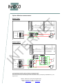
Option: Moisture-measurement
Sensor Type I
Version: v1.0
junctionbox
KLK1
pk
Junction-box
KLK1
Text printed Bold and in Italics, refer to functions on the Operator Panel.
Bold printed words refer to names used in drawings Appendix A and B.
Z:\Documenten\SG-bepaler\Handleiding\Docs\Docs actual\ENG\Installing and adjusting DENSIMETER v4_2.doc
Page 35 of 44
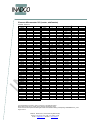
Appendix D: Parameters Frequency Converter
These parameters may not be changed.
Siemens Micromaster 410 without PTC temperature-sensor in motor
Default Parameter Value
1
0
21
0
0
0
230
2
1
230
3.25
0.75
0
0
50
0
0
0
4
2
100
100
150
2
1
12
9
0
P0758
P0759
P0760
P0761
P0810
P0927
P0970
P0971
P1000
P1001
P1002
P1003
P1031
P1032
P1040
P1058
P1059
P1060
P1061
P1070
P1075
P1080
P1082
P1091
P1120
P1121
P1130
P1131
P1132
P1133
P1134
P1135
P1200
P1202
P1203
IN
P0719(2)
P0724
P0731
P0748
P0753
P0757
Default Parameter Value
0
10
100
0
0
15
0
0
2
0
5
10
0
1
5
5
5
10
10
755:0
0
0
50
0
10
10
0
0
0
0
0
5
0
100
100
P1210
P1215
P1216
P1217
P1232
P1233
P1236
P1240
P1300
P1310
P1311
P1312
P1316
P1320
P1321
P1322
P1323
P1324
P1325
P1333
P1335
P1340
P1800
P2000
P2009[2]
P2010[2]
P2011[2]
P2012[2]
P2013[2]
P2014[2]
P2016[2]
P2019[4]
P2167
P3900
1
R
N
3
15
147
2
1
12
9
TE
P0003
P0004
P0005
P0010
P0100
P0201
P0210
P0290
P0300
P0304
P0305
P0307
P0308
P0309
P0310
P0311
P0335
P0340
P0350
P0610
P0611
P0614
P0640
P0700
P0701
P0702
P0703
P0704
0
52:3
0
3
0
4
Default
1
0
1
1
100
0
0
1
0
50
0
0
20
0
0
0
0
0
0
10
0
0
4
50
0
6
0
2
127
0
52:0
52:0
1
0
ET
Version: V410.1.1
Parameter Value
30
0
50
0.5
0.3
0.3
0.3
0.3
0.3
100
16
Text printed Bold and in Italics, refer to functions on the Operator Panel.
Bold printed words refer to names used in drawings Appendix A and B.
Z:\Documenten\SG-bepaler\Handleiding\Docs\Docs actual\ENG\Installing and adjusting DENSIMETER v4_2.doc
Page 36 of 44
INADCO , Meerheide 18, 5521DZ Eersel (Netherlands)
Phone :++31 497 51 72 91 Fax :++31 497 51 74 69
E-mail : [email protected] Website : www.inadco.nl
Siemens Micromaster 410 with PTC temperature-sensor in motor
Default Parameter Value
1
0
21
0
0
0
230
2
1
230
3.25
0.75
0
0
50
0
0
0
4
2
100
100
150
2
1
12
9
0
P0758
P0759
P0760
P0761
P0810
P0927
P0970
P0971
P1000
P1001
P1002
P1003
P1031
P1032
P1040
P1058
P1059
P1060
P1061
P1070
P1075
P1080
P1082
P1091
P1120
P1121
P1130
P1131
P1132
P1133
P1134
P1135
P1200
P1202
P1203
0
10
100
0
0
15
0
0
2
0
5
10
0
1
5
5
5
10
10
755:0
0
0
50
0
10
10
0
0
0
0
0
5
0
100
100
P1210
P1215
P1216
P1217
P1232
P1233
P1236
P1240
P1300
P1310
P1311
P1312
P1316
P1320
P1321
P1322
P1323
P1324
P1325
P1333
P1335
P1340
P1800
P2000
P2009[2]
P2010[2]
P2011[2]
P2012[2]
P2013[2]
P2014[2]
P2016[2]
P2019[4]
P2167
P3900
15
147
2
1
12
29
9
0
52:3
0
3
0
4
Default
1
0
1
1
100
0
0
1
0
50
0
0
20
0
0
0
0
0
0
10
0
0
4
50
0
6
0
2
127
0
52:0
52:0
1
0
1
30
0
50
0.5
0.3
0.3
0.3
0.3
0.3
100
16
IN
P0719(2)
P0724
P0731
P0748
P0753
P0757
Default Parameter Value
R
N
3
TE
P0003
P0004
P0005
P0010
P0100
P0201
P0210
P0290
P0300
P0304
P0305
P0307
P0308
P0309
P0310
P0311
P0335
P0340
P0350
P0610
P0611
P0614
P0640
P0700
P0701
P0702
P0703
P0704
ET
Version: V410.1.1
Parameter Value
Text printed Bold and in Italics, refer to functions on the Operator Panel.
Bold printed words refer to names used in drawings Appendix A and B.
Z:\Documenten\SG-bepaler\Handleiding\Docs\Docs actual\ENG\Installing and adjusting DENSIMETER v4_2.doc
Page 37 of 44
INADCO , Meerheide 18, 5521DZ Eersel (Netherlands)
Phone :++31 497 51 72 91 Fax :++31 497 51 74 69
E-mail : [email protected] Website : www.inadco.nl
Siemens Micromaster 310 (vector, midimaster)
Version: V310.1.1
0,5
0,3
0,3
30
Parameter
P062
P063
P064
P065
P066
P069
P070
P071
P072
P073
P074
P075
P076
P077
P078
P079
P080
P081
P082
P083
P084
P085
P086
P087
P088
P089
P091
P092
P093
P094
P095
P099
P101
P111
P112
P113
P121
P122
P123
P124
P125
P128
P131
P132
P133
P134
P135
P137
P138
P139
IN
Value
0
1
Default
8
1
1
1
0
1
0
0
250
0
3
0
0/4
1
100
0
***
50
***
***
***
***
150
0
0
***
0
6
0
50
0
0
0
***
***
***
1
1
1
1
1
120
-
1
nvt
2
R
N
0
3
Default
0
10
10
0
5
0
1
0
1
0
0
50
0
0
0
1
0
2
0
50
0
0
0
0
0
0
0
5
5
10
10
0
5
10
15
20
0
25
30
35
40
0
1
2
6
6
6
0
1
6
10
Parameter
P140
P141
P142
P143
P186
P201
P202
P203
P204
P205
P206
P207
P208
P210
P211
P212
P220
P321
P322
P323
P356
P386
P387
P700
P701
P702
P720
P721
P722
P723
P724
P725
P726
P880
P910
P918
P922
P923
P927
P928
P930
P931
P944
P947
P958
P963
P967
P968
P970
P971
Value
nvt
ET
Value
TE
Parameter
P000
P001
P002
P003
P004
P005
P006
P007
P009
P010
P011
P012
P013
P014
P015
P016
P017
P018
P019
P021
P022
P023
P024
P025
P026
P027
P028
P029
P031
P032
P033
P034
P040
P041
P042
P043
P044
P045
P046
P047
P048
P049
P050
P051
P052
P053
P054
P055
P056
P057
P061
50
1375
2
230
0,37
147
15
0,37
5
2
Text printed Bold and in Italics, refer to functions on the Operator Panel.
Bold printed words refer to names used in drawings Appendix A and B.
Z:\Documenten\SG-bepaler\Handleiding\Docs\Docs actual\ENG\Installing and adjusting DENSIMETER v4_2.doc
Page 38 of 44
INADCO , Meerheide 18, 5521DZ Eersel (Netherlands)
Phone :++31 497 51 72 91 Fax :++31 497 51 74 69
E-mail : [email protected] Website : www.inadco.nl
Default
200
0
1
0
0
1
0
100
0
0
100
0
0
50
0
6
1
1
0
0
0
0
0
0
0
1
Siemens Sinamics G110
3
1
0
21
0
0
0
0
0
0
230
3.25
0.12
0
0
50
0
0
0
1
1
4
2
100
110
150
2
1
12
9
0
0
0
3
5
0
3
0
P0758
P0759
P0760
P0761
P0802
P0803
P0810
P0927
P0970
P0971
P1000
P1001
P1002
P1003
P1031
P1032
P1040
P1058
P1060
P1080
P1082
P1091
P1110
P1120
P1121
P1130
P1134
P1135
P1200
P1202
P1203
P1210
P1215
P1216
P1217
P1232
P1233
IN
Default Parameter Value
0
10
100
0
0
0
0
15
0
0
2
0
5
10
0
1
5
5
10
0
50
0
0
10
10
0
0
5
0
100
100
1
0
1
1
100
0
1
R
N
0.75
Default Parameter Value
15
147
2
1
12
9
TE
P0003
P0004
P0005
P0010
P0014[3]
P0100
P0201
P0290
P0295
P0304
P0305
P0307
P0308
P0309
P0310
P0311
P0335
P0340
P0346
P0347
P0350
P0610
P0611
P0614
P0640
P0700
P0701
P0702
P0703
P0704*
P0704**
P0719(2)
P0724
P0731
P0748
P0753
P0757
29
5
P1240
P1300
P1310
P1311
P1312
P1316
P1320
P1321
P1322
P1323
P1324
P1325
P1335
P1340
P1800
P2000
P2010
P2011
P2012
P2013
P2014
P2016
P2167
P3900
Default
1
0
50
0
0
20
0
0
0
0
0
0
0
0
8
50
6
0
2
127
0
0
1
0
ET
Version : V110.1.1
Parameter Value
30
0
50
0.5
0.3
0.3
4
16
P0704* = without the use of a PTC
P0704** = with the use of a PTC
Text printed Bold and in Italics, refer to functions on the Operator Panel.
Bold printed words refer to names used in drawings Appendix A and B.
Z:\Documenten\SG-bepaler\Handleiding\Docs\Docs actual\ENG\Installing and adjusting DENSIMETER v4_2.doc
Page 39 of 44
INADCO , Meerheide 18, 5521DZ Eersel (Netherlands)
Phone :++31 497 51 72 91 Fax :++31 497 51 74 69
E-mail : [email protected] Website : www.inadco.nl
Appendix E: Parameters Densimeter
Version: V2.0
Green cells * :
Yellow cells ** :
Blue cells *** :
Free for changing
No changing allowed
May only be changed after consult with INADCO
Arm
Cylinder
Parameter
Cylinder full max Incr
Full counter
Material filling min Incr.
Skid-detection min
pulses
Parameter
Check Full Pos ***
Margin
StartUnlo Pos ***
Stop Unload Pos ***
Margin
Leak detection ***
Margin
Pos. Switch in the flow
Correction Cooling **
Correction Heating **
Value
Value
Value
IN
Parameter
Emptying cylinder
Closing cylinder
Stand-still
Start delay
Stop delay
Pause delay
Analogue
Parameter
Vav Analogue-input
Spike Analogue-input
Filter AI-cylinder
Value
Raw AI-cylinder
Default
0,250
2
0,350
10
Parameter
Accretion detection
Warning detection
Accretion
Blockage
Retries
Leak detection allowed
Value
Default
0,500
0,999
3
0,5
Default
2
2
2
2
2
0
Parameter
Restart delay
Stop delay Belt
Refresh communication
Motion time cylinder PLC
Motion time cylinder
Siwarex
Value
Default
0
1+0,5
0,5
Default
1
1
2
Parameter
Vav Analogue input Arm
Spike Analogue inp Arm
Motion range Cyl PLC
Motion range Cyl
Siwarex
Value
Parameter
Communication Out
Value
-
Communication
Parameter
Communication IN
Value
Default
2000
200
3043
3250
845
1900
200
1,01
0,99
ET
Default
3500
595
400
450
500
600
2675
1000
2850
1000
TE
Time
Value
3500
R
N
Parameter
Limit Unloading **
Margin
Limit Loading Pos **
Margin
Loading Pos *
Margin
Reversal Pos ***
Margin
CheckIncrease Pos ***
Margin
Default
off
-
Default
1
1
0,4
-
Default
off
Text printed Bold and in Italics, refer to functions on the Operator Panel.
Bold printed words refer to names used in drawings Appendix A and B.
Z:\Documenten\SG-bepaler\Handleiding\Docs\Docs actual\ENG\Installing and adjusting DENSIMETER v4_2.doc
Page 40 of 44
INADCO , Meerheide 18, 5521DZ Eersel (Netherlands)
Phone :++31 497 51 72 91 Fax :++31 497 51 74 69
E-mail : [email protected] Website : www.inadco.nl
Appendix F: Timing diagram
Version: V2
Printer prints
a label (if present)
the arm stops at checkfullpos.
stand-still time default 2 sec
ET
total time after ending start-signal 11-16 sec.
moving arm to
checkfullpos. default 2 sec
adjustable time
emptying cylinder
default 2 sec
unloading
cylinder
moving arm for
unloading cylinder
default 3 sec
R
N
ending strike
0-5 sec
adjustable
stop-delay
default 2 sec
flashing
fast (2 Hz)
continuous
operation
TE
continuous
adjustable restart-delay
before movement starts
again. default 0 sec
completes movement arm
stops in loadpos.
flashing
slow (1 Hz)
min 5 sec
after start
continuous
first strike
5 sec
Activate
Densimeter
PAUSE
PLC input 1.3
terminal 8
V2.0
adjustable
start-delay
default 2 sec
flashing
fast (2 Hz)
LED K3 on
Operator Panel
START-SIGNAL
PLC input 1.1
terminal 7
IN
continuous
operation
Text printed Bold and in Italics, refer to functions on the Operator Panel.
Bold printed words refer to names used in drawings Appendix A and B.
Z:\Documenten\SG-bepaler\Handleiding\Docs\Docs actual\ENG\Installing and adjusting DENSIMETER v4_2.doc
Page 41 of 44
INADCO , Meerheide 18, 5521DZ Eersel (Netherlands)
Phone :++31 497 51 72 91 Fax :++31 497 51 74 69
E-mail : [email protected] Website : www.inadco.nl
80
240
160
INADCO , Meerheide 18, 5521DZ Eersel (Netherlands)
Phone :++31 497 51 72 91 Fax :++31 497 51 74 69
E-mail : [email protected] Website : www.inadco.nl
F
134
E
240
1
2
850
500-900
3
File onderdeel: SG BEPALER 2 met rol in haaks.asm
File:
SG BEPALER 2 met rol in haaks.dft
4
All dimensions are in mm.
Project:
Benaming:
5
Materiaal:
MONTAGE NIEUWE SG-BEPALER haakse opstelling
6
Deb: INADCO
Top level shovel is equal or
just below center drum belt
Distance between belt and
shovel appr 3 cm.
6
nvt
A3
Naam:
Datum:
Datum Wijz.:
8
7
Scale:
Blad:
8
ADU
28-11-2009
19-1-2011
ET
Shield
7
copyright 2010 inadco
INADCO
Meerheide 18 5521 DZ Eersel
www.inadco.nl
Tel: +31 (0) 497-517291
[email protected]
Fax: +31 (0) 497-517469
R
N
5
The dimensions are valid for the next installations.
- Cylinder and motor are mounted like in this drawing.
- Cylinder and motor are mounted mirrored.
- Cylinder and motor are mounted on the same level.
Within this radius
NO obstacles
4
TE
3
Depends on Beltwidth
and materialflow
950
D
C
B
A
2
IN
°
20
1
F
E
D
C
B
A
Appendix G: Installation
Situation: Corner overflow
Version: v2.0
Ø18
Text printed Bold and in Italics, refer to functions on the Operator Panel.
Bold printed words refer to names used in drawings Appendix A and B.
Z:\Documenten\SG-bepaler\Handleiding\Docs\Docs actual\ENG\Installing and adjusting DENSIMETER v4_2.doc
Page 42 of 44
240
160
INADCO , Meerheide 18, 5521DZ Eersel (Netherlands)
Phone :++31 497 51 72 91 Fax :++31 497 51 74 69
E-mail : [email protected] Website : www.inadco.nl
F
80
E
134
1
850
2
Top level shovel is equal or
just below center drum belt
Distance between belt and
shovel appr 3 cm.
3
File onderdeel: nvt
File:
SG BEPALER 2 met rol in lijn.dft
4
All dimensions are in mm.
6
Project:
Benaming:
5
MONTAGE NIEUWE SG-BEPALER in lijn
Materiaal:
6
7
7
copyright 2010 inadco
INADCO
Meerheide 18 5521 DZ Eersel
www.inadco.nl
Tel: +31 (0) 497-517291
[email protected]
Fax +31 (0) 497-517469
Scale:
nvt
A3
Naam:
Datum:
Datum Wijz.:
Blad:
ET
Shield
Deb: INADCO
R
N
5
The dimensions are valid for the next installations.
- Cylinder and motor are mounted like in this drawing.
- Cylinder and motor are mounted mirrored.
- Cylinder and motor are mounted on the same level.
355
Within this radius
NO obstacles
4
TE
Depends on Beltwidth
and materialflow
3
250-750
D
C
B
A
2
IN
20°
Ø18
1
8
ADU
31-8-2010
31-8-2010
8
F
E
D
C
B
A
Situation: Overflow In Line
Version: v2.0
240
Text printed Bold and in Italics, refer to functions on the Operator Panel.
Bold printed words refer to names used in drawings Appendix A and B.
Z:\Documenten\SG-bepaler\Handleiding\Docs\Docs actual\ENG\Installing and adjusting DENSIMETER v4_2.doc
Page 43 of 44
Appendix Z: Declaration of Incorporation
IN
TE
R
N
ET
Version: V1.0
Text printed Bold and in Italics, refer to functions on the Operator Panel.
Bold printed words refer to names used in drawings Appendix A and B.
Z:\Documenten\SG-bepaler\Handleiding\Docs\Docs actual\ENG\Installing and adjusting DENSIMETER v4_2.doc
Page 44 of 44
INADCO , Meerheide 18, 5521DZ Eersel (Netherlands)
Phone :++31 497 51 72 91 Fax :++31 497 51 74 69
E-mail : [email protected] Website : www.inadco.nl