1
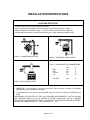
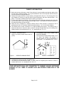
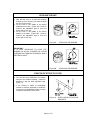
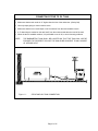
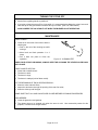
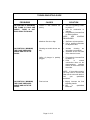
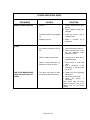
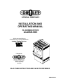
INSTALLATION AND
OPERATING MANUAL
OIL BURNING STOVE
ALASKA 2000
Vérified and tested following
CAN/CSA B140.3 et UL 896 standards by:
Intertek Testing Services
Fabricated by:
1700 Léon-Harmel
Québec, (Québec)
G1N 4R9
READ THESE INSTRUCTIONS AND SAVE FOR REFERENCE
990830/45004A
TABLE OF CONTENT
TECHNICAL DATA ......................................................................................................................................... 1
INSTALLATION INSTRUCTIONS .................................................................................................................. 2
Locating the stove ........................................................................................................................................2
Chimney informations...................................................................................................................................3
Connecting the stove to the chimney ...........................................................................................................4
Leveling the unit ...........................................................................................................................................5
Fixation of stove to floor ...............................................................................................................................5
Connecting stove to oil tank .........................................................................................................................6
Adjusting the draught ...................................................................................................................................7
Draught regulator .........................................................................................................................................7
OPERATION INSTRUCTIONS ....................................................................................................................... 8
Combustible .................................................................................................................................................8
Lighting.........................................................................................................................................................8
Changing intensity........................................................................................................................................9
Turning the stove off...................................................................................................................................10
Maintenance...............................................................................................................................................10
Troubleshooting guide................................................................................................................................11
SPARE PARTS ............................................................................................................................................. 13
W A R R A N T Y........................................................................................................................................... 15
TECHNICAL DATA
HIMALAYA OIL BURNING STOVE
COMBUSTIBLE :
HEAT INPUT :
Minimum :
Maximum :
FLOWRATE :
Minimum :
maximum :
MINIMUM DRAUGHT REQUIRED :
EFFICIENCY :
with fan :
without fan :
OIL NO 1
kW
BTU/h
4,8
16 600
10,7
36 800
cc/min
litres/h
9,9
0,59
17,3
1,04
0,05 INWC
%
81,5
76,5
CLEARANCES TO COMBUSTIBLES
Back
Side
Corners
Top
Mm
150
150
150
915
OIL NO 2
kW
BTU/h
3,7
12 800
10,3
35 550
cc/min
litres/h
8,5
0,35
16,1
0,97
0,05 INWC
%
76
73
DIMENSIONS
in
6
6
6
36
Height :
Width :
Depth :
Ø outlet flue pipe :
Ø burner :
A MINIMUM CLEARANCE OF 9’’ FROM
PIPE TO COMBUSTIBLES SHOULD BE
ALLOWED.
Glass ( 3 ) :
Weight :
Page 1 of 15
mm
800
635
485
130
255
in
31 ½
25
19 1/8
5
10
460 x 280
80kg
18 x 11
175 lbs
INSTALLATION INSTRUCTIONS
LOCATING THE STOVE
•
•
•
•
Install the stove as close to the chimney as possible.
Many configuration are possible, the most frequent are illustrated in figures 1,2 and 3.
Respect clearances indicated on page 1. They have been tested according to approvals.
Always respect clearances of stove pipe manufacturers. Larger clearances always prevail.
Figure 1 : CORNER INSTALLATION
Figure 2 : PARRALLÈL INSTALLATION
Table 1 : CLEARANCES TO COMBUSTIBLES
Back
Side
Corners
Top
mm
150
150
150
915
in
6
6
6
36
Flue Pipe
230
9
Figure 3 : WALL INSTALLATION
• IMPORTANT: It is essential to ensure that the room were the stove is located is sufficiently
ventilated to provide an adequate air supply.
• It is possible that if your home is well insulated, that you will have to install an outside fresh air
intake.
THE BURNING OF ONE LITRE OF FUEL (OIL) REQUIRES APPROXIMATELY 30 M3 OF AIR AND
WILL PRODUCE ABOUT 0.8 KG OF WATER OF WATER VAPOR AND 9 M3 OF CARBONE
DIOXIDE AND ATMOSPHERIC NITROGEN. A SOURCE OF AIR FROM THE OUTSIDE IS NEEDED
TO REPLACE COMBUSTION AIR. Ref : standard B-139 4.1.4
Page 2 of 15
CHIMNEY INFORMATIONS
• Before the hook up of the stove, check if the chimney is in good condition and that the quality of the
flue will allow a sufficient draught. For a good combustion, refer to the technical data of the stove
to know the minimum draught required.
• Factory built a type chimney or L type chimney are approved for this unit. The chimney has to be
well insulated, a chimney to cold can affect the gas temperature and lower draught effects. Low
gases To will tend to condense and freeze or leak in your chimney.
• 5" factory built chimney is required. Using a larger flue tend to expand combustion gas and cools
them off witch has for result of lowering the draught effects. Gas expansion reduces the speed of
the draught and have the same effects.
• When the unit is installed on a masonry chimney witch is often oversize, it’s required to use a
stainless steel liner of 5" diameter inside the existing chimney. ref : B-139 4.2.2.6 standard
• The chimney has to reach a minimum of 15' high (including stove pipes). The chimney has to
extend not less than 3' above the point it exits the roof and 2' higher than any roof, building other
obstacle within a horizontal distance of 10'. ref.: standard B-139 - 4.2.2.11.
• CHEMNEY MINMUM HEIGHT :
Height of chemney should inferior than 15’
(4.6 m).
• CLEARANCES WITH ROOF SUMMIT AND
BUILDING NEARBY :
The chimney flue shall extend at least 2’ (0,6
m) above the highest roof surface or
structure within 10’ (3,0 m) horizontally of
the chimney. ref.: standard B-139 - 4.2.2.11
Figure 4:
Figure 5:
CHEMNEY MINMUM HEIGHT
CHIMNEY CLEARANCES
• CLEARANCE FROM ROOFING INTERSECTION :
The chimney flue shall extend at least 3’ (1,0 m) above the highest point at which it comes in
contact with the roof. ref.: standard B-139 - 4.2.2.11.
YOUR APPLIANCE SHALL BE CONNECTED TO CHIMNEY HAVING SUFFICIENT
DRAUGHT AT ALL TIMES TO ASSURE SAFE AND PROPER OPERATION OF THE
BURNER
Page 3 of 15
CONNECTING THE STOVE TO THE CHIMNEY
• The gases are vented from he back of the unit. The female part of the black pipe connector has to
be installed toward the flue connector of the stove. Secure all connections with the (3) self taping
screws, with 120o distance between each of them.
• The connection between stove pipes and chimney has to be perfectly sealed.
• A maximum horizontal lent of 5' is allowed. Make sure to have a 1/4" slope per foot minimum.
• Do not use more than two 90o Elbows while connecting the stove to the chimney.
• It is strictly forbidden to pass through combustible materials walls, floors and ceilings with stove
pipe connectors. Ref : Standard B-139 4.2.5.5.
• DIRECT HORIZONTAL CONNECTION :
You may choose to connect your stove to
the chimney with an horizontal flue pipe.
• CEILING CONNECTION :
In the case where your chimney starts from
the ceiling, use one 90º elbow and the
necessary straight sections.
Figure 6:
Figure 7:
HORIZONTAL CONNECTION .
• DO NOT CONNECT MORE THAN ONE
STOVE TO YOUR CHIMNEY.
• FIX FLUE PIPES
METAL SCREWS.
TOGETHER
WITH
CEILING CONNECTION .
• VERTICAL CONNECTION :
IT is recommended to not use more than two
(2) 90º elbows and the necessary straight
sections to connect your stove to the
chimney.
• MAKE SURE YOU RESPECT A ¼’’ SLOPE
PER FOOT OF HORIZONTAL PIPE
LENGTH.
• RESPECT CAREFULLY CLEARANCES TO
COMBUSTIBLES PRESCRIBED BY FLUE
PIPES MANUFACTURERS.
• FLUE
PIPES
CLEARANCES
TO
COMBUSTIBLES DEPEND ON FLUE
PIPES TYPE AND MANUFACTURERS
Figure 8:
Page 4 of 15
VERTICAL CONNECTION .
LEVELING THE UNIT
• Now that the stove is in place and properly
hooked up to the chimney, you have to adjust
the level on the burner.
• Put the level in the middle of the burner
paralleled to the door. (Figure 9A). Screw or
unscrew the adjustable legs to level the
burner with a 7/16" key.
• Put the level in the middle of the burner
parallel to the sides. (Figure 9B). Screw or
unscrew the adjustable legs to level the
burner with a 7/16" key.
Figure 9A:
LEVELLING THE BURNER
Figure 9B:
LEVELLING THE BURNER
IMPORTANT :
IT IS VERY IMPORTANT TO LEVEL THE
BURNER TO ALLOW A PROPER OIL VAPOR
DISTRIBUTION THROUGH THE RINGS, AND A
BETTER OIL INLET.
FIXATION OF STOVE TO FLOOR
• The unit has to be stabilized in its location
using the two fixation brackets. Install the
brackets on the two back adjustable legs.
(figure 11)
• If the flooring is made of combustible
material it would be preferable to install the
unit on an non combustible surface covering
at least the dimensions of the stove.
Figure 10:
Page 5 of 15
INSTALLATION OF FIXATION
BRACKETS
CONNECTING STOVE TO OIL TANK
• Make sure that the tank outlet is 12" higher than the inlet of the carburetor. (Gravity fed)
• Use only caper piping to connect tank to stove.
• Make sure that there is a small slope on the connection from the tank toward the stove.
• A 3" down slope is needed on the tank itself, from the outlet towards the other end of the tank.
• When the tank is installed outdoors, it is preferable to use oil #1, to avoid viscosity problems.
NOTE :
THE BAROMETRIC TANK SHALL BE LOCATED SO THAT THE TANK WILL NOT BE
EXPOSED TO THE DIRECT RAYS OF THE SUN OR BE ADJACENT TO ANY SOURCE
OF INTENSE HEAT.
Figure 11 :
STOVE AND OIL TANK CONNECTION
Page 6 of 15
ADJUSTING THE DRAUGHT
• Your stove operated with natural draught, created by the ascension of combustion gases in the
chimney. This movement creates a siphon effect in the stove and forces ambient air to go in the
burner by the holes in its surround. These orifices let air in for combustion.
• For the unit to function properly, it is essential to check the quality of the draught using a draught
gauge. The draught is usually measured in inches of water column.
• Check the minimum draught required of the unit on page 1. The draught required of the unit on
page 1. The draught mentioned has to be reached rapidly at a minimum settling (position #1).
• Depending on the model, the draught can be taken by the orifice on the cooking surface. The
measure can also be taken by the orifice on the draught regulator usually plugged by a rubber cap.
The orifice on the cooking surface is still the best area.
IMPORTANT : ALWAYS MEASURE THE DRAUGHT WITH ALL VENTILATION EQUIPMENT
INSTALLED IN THE HOUSE (RANGE HOOD, BATHROOM FAN, AIR EXCHANGER, DRYER, ETC
IN OPERATION.)
ref. : standard CAN/CSA B-139 art. 4.1.5.
DRAUGHT REGULATOR
• An excessive draught is as bad as a draught
to low.
• The regulator controls the draught when it is
excessive (in high winds for exemple).
• If the draught exceeds 0.08 in of water
column, you will have to adjust the regulator.
• To adjust the draught you have to screw or
unscrew the counterweight on the regulator.
Regulator open lowers the draught regulator
closed increases the draught.
Figure 12:
DRAUGHT REGULATOR
THE ONLY RIGHT WAY OF MEASURING THE DRAUGHT IS TO USE A DRAUGHT GAUGE THAT
GIVES A READING IN INCHES OF WATER COLUMN. ALL OTHER METHOD (CANDLE,
MATCHES, ETC.) ARE UNRELIABLE.
INSTALLATION OF YOUR STOVE HAS TO BE IN ACCORDANCE WITH CAN/CSA B-139
INSTALLATION CODE FOR OIL-BURNING EQUIPMENT IN CANADA AND STANDARD NFPA 31
NATIONAL FIRE PROTECTION ASSOCIATION STANDARD FOR OIL-BURNING EQUIPMENT IN
THE U.S..
THE INSTALLATION SHALL BE MADE BY A QUALIFIED PERSON MEMBER OF THE
CORPORATION IN FORCE IN YOUR AREA.
Page 7 of 15
OPERATION INSTRUCTIONS
COMBUSTIBLE
• Your stove has been design to work with oil #1 or #2. DO NOT USE GASOLINE, CRANKCASE
OIL OR ANY OIL CONTAINING GASOLINE. Drolet Stoves & Fireplaces declines all responsibility
regarding damage cause by using other combustibles.
• Best results are obtained when using oil #1. Make sure to use oil without impurities wich may plug
filters and valve’s orifice. Impurities only give an improper combustion.
LIGHTING
BEFORE LIGHTING
• make sure that :
The tank is full;
The isolating valve is open;
• See that the (3) rings are in the right
position. Each of them are stamped A, B
and C (figure 13).
• Make sure that the flow regulating handle is
in the « 0 » position (figure 14b).
• If it’s not already done, arm down the valve’s
lever located behind the stove (figure 14A).
• Wait for the valve to fill up and let the level
stabilize.
• BEFORE ATTEMPTING TO LIGHT YOUR
STOVE, MAKE SURE THAT THE FLOW
REGULATING HANDLE IS IN THE 0
POSITION.
Figure 13:
Figure 14B:
Figure 14B: CONSTANT
LEVEL
CONTROL VALVE (CARBURATOR)
FLOW
Page 8 of 15
RINGS POSITION
ARMING / DEARMING FLOW
CONTROL VALVE (CARBURATOR).
LIGHTING (CONT’D)
• Place the flow regulating handle on the "1" position, as soon as the oil enters the burner
return to "0" position.
• Open the door and pore into the burner 2 to 3 once (75 ml) of lighting gel or wood
alcohol.
NOTE : USE OF LIGHTING GEL IS BETTER OF A SAFE IGNITION.
• With a long wood match or a BBQ lighter ignite carefully and close the door.
• After a couple of minutes (before alcohol goes out) the burner and the chimney are hot,
place the flow regulator handle on "1" position.
Note : Do not leave matches or other materials in the burner in order to keep it
clean. It allows a better combustion.
IF YOU MISS THE STOVE’S LIGHTING, ALWAYS WAIT FOR THE
BURNER TO COOL DOWN TO ROOM TEMPERATURE BEFORE
USING BURNING ALCOHOL AGAIN OR ELSE, USE COMMERCIAL
LIGHTING MATERIAL (SOLID) OR A PIECE OF COTTON DAMPED
IN OIL.
IF, FURTHER TO SOME MISOPERATION, THE BURNER IS FILLED
WITH IMPORTANT QUANTITIES OF OIL, ALL OF THE OIL MUST
FIRST BE REMOVED BEFORE LIGHTING THE STOVE AGAIN.
CHANGING INTENSITY
• Always wait 10 minutes minimum before increasing the flow (between each position). This allows
flames to stabilize and avoid suiting up. No waiting is needed to decrease the flow.
• Cette précaution n’est cependant pas nécessaire pour diminuer le débit de carburant.
Page 9 of 15
TURNING THE STOVE OFF
• Set the flow regulating handle to position 0.
• If you plan to keep the stove off for a long while, it is recommended to disarm the valve’s lever and
close the tap on the pipe between the stove and your oil tank. (See TOP VIEW above).
ALWAYS KEEP THE VALVE SHUT OFF WHEN THE BURNER IS NOT OPERATING
MAINTENANCE
ONCE A WEEK :
• Clean the oil inlet tube of the burner with the
cleaning tee :
Push in the rod of the cleaning tee while
turning it
Move back and forth operation 2 or 3
times;
Pull it back into place to finish the
operation.
Figure 15 : CLEANING TEE
WHEN YOUR STOVE IS RUNNING, ALWAYS KEEP THE CLEANING TEE LEVER PULLED BACK
INTO PLACE.
ONCE A MONTH OR TWO :
• Clean with a metallic brush :
• The burner’s shell;
• The burner’s rings;
• The burner’s catalyst (in blue flame model).
AT THE BEGINNING OF EACH HEATING SEASON :
• Clean the valve and tank filters;
• Inspect the smoke box through the opening of the rear flue outlet.;
• Clean the chimney and flue pipe.
MAKE SURE THAT ALL HAND VALVES ARE CLOSED BEFORE CLEANING PROCEDURES.
WHEN NEEDED :
• Clean the glass door and gaskets.
• The glasses have to be cleaned only when the stove is cold. Use commercial product for this
purpose, or a water and vinegar solution.
Page 10 of 15
TROUBLESHOOTING GUIDE
PROBLEMS
CAUSES
SOLUTION
ON POSITION 6 (MAXIMUM)
THE FLAME IS LONG AND
SMOKY, THERE IS SUIT
BUILD UPON THE GLASS
Position 6 was reached too
quickly.
1. Set flow regulating handle
to position 1.
2. wait for combustion to
stabilize.
3. Progressively increase flow
to desired position.
NOTE :
SEE
LIGHTING
PROCEDURES.
Maximum flow is too high
1. Set flow to a lower position
2. Call a qualified technician
to adjust the valve.
Cleaning tee and/or burner are
dirty
1. Activate
cleaning
tee
according to procedures
2. Schedule at the next shut
off to clean the burner.
Orifice of plunger is partially
plugged.
1. Progressively increase flow
to position 6.
2. Push
in
manual
consecutive times on the
thermostatique
regulator
bottom to remove dirt form
the orifice.
ON POSITION 1 (MINIMUM)
THE FLAME PRODUCES
SMOKE AND SUITS THE
GLASS
NOTE : If the problem persist,
you may have to remove and
clean out the valve with alcohol.
Call
your
specialized
technician.
ON POSITION 1 (MINIMUM)
THE FLAME PRODUCES
SMOKE AND SUITS THE
GLASS
Flow is to low
Page 11 of 15
1. Slightly increase the flow
regulating handle.
2. Call
a
specialized
technician.
TROUBLESHOOTING GUIDE
PROBLEMS
THE FLAME PRODUCES
SMOKE, IN ANY POSITION
FLAME GOES OUT TO
ITSELF
THE STOVE MAKES NOISE,
GOES OUT AND LIGHT UP
AGAIN
CAUSES
Door gasket
properly
is
not
SOLUTION
selling
1. Tighten door by turning
counter clockwise the door
handle.
2. Check if gasket needs to be
changed.
The burner orifices are plugged
up
1. Clean the burner with a
metallic brush.
Draught is too low
1. Make it checked
technician
Oil level in the tank is too low
1. Fill up the tank.
Air pocket is stocked in the oil
line
1. Call a technician to the line
2. Make sure that the oil line
has an adequate slope
towards the tank.
Oil #2 is used in exterior tank
1. Use only oil #1 when tank is
installed outside.
Partial or total obstruction by
impurities in oil line or filters
1. Check filters on tank and
valve.
2. Ask a technician if the
cleanness of the tank and
line is OK.
The stove has been lit while
excess of oil was in the burner
1. Position the flow regulating
handle to 0.
2. Let the stove cool down.
3. Clean
the
burner
if
necessary.
Note : Never light the stove
when the burner is full of oil.
Sponge the oil out before
lighting.
Page 12 of 15
by
a
SPARE PARTS
After years of use, if you need to replace some parts, please contact your SUPPLIER or one of our
Drolet approved DEALERS.
• Give him product data as displayed in your warranty voucher or on your appliance’s name plate at
the rear. Keep the warranty voucher even after its EXPIRY date.
• Our dealers are in possession of all spare parts nomenclatures and technical data about our
products, and will provide you with the spare parts you need and any maintenance intervention
within the scope of their professional competence.
NO
DESCRIPTION
CODE
1
Handle............................................................................................................................3-132
2
Door .............................................................................................................................2-9917
3
Asbestos sealing joint for window panes...................................................................3-40015
4
Pyrex slivers ..............................................................................................................3-60007
5
Door frame ..............................................................................................................2-9917-01
6
Asbestos sealing joint for door ..................................................................................3-40025
7
Lower front grill ............................................................................................................2-9352
8
Top front grill ................................................................................................................2-9965
9
Side panels (2).............................................................................................................2-9950
10
Cover support system.............................................................................................2-9901-02
11
Fan control .................................................................................................................3-44080
12
Thermo disc ...............................................................................................................3-44044
13
Draught regulator.......................................................................................................3-60003
14
Fan.............................................................................................................................3-44070
15
Fan.............................................................................................................................3-60000
16
Valve support...............................................................................................................2-9958
17
Valve heat shield .........................................................................................................2-9911
18
Valve side shield.....................................................................................................2-9911-02
19
Pot liner........................................................................................................................2-9953
20
Cleaning tee...............................................................................................................3-60002
21
Burner (pot)................................................................................................................3-60001
22
Burner rings (top, middle and bottom) .........................................................................2-9957
Page 13 of 15
Page 14 of 15
WARRANTY
The Drolet Stoves & Fireplaces warranty applies to the original buyer only. This warranty may not
be transferred to a second person and becomes effective on the date of purchase. Proof of
purchase is necessary to validate the warranty and to establish the warranty coverage period.
The warranty is conditional to normal residential use of the product. Any use other than that for
which the product was intended will invalidate the warranty. The warranty covers repairs and (or)
parts replacement under the terms established by Drolet Stoves & Fireplaces.
PRODUCT
Wood (except Hunter)
GAS
OIL
GODIN
EXTERIOR FIREPLACE
HUNTER
FIREBOX
5 years
PAINT
1 year
COMPONENT
1 year
5 years
5 years
5 years
1 year
N/A
1 year
1 year
1 year
N/A
N/A
1 year
1 year
1 year
N/A
N/A
FIREBOX AND PAINT
The warranty covers manufacturer defects and materials.
COMPONENTS
The following components are covered by the one-year warranty as follows:
• Woodstoves :
Ceramic glass, refractory bricks, gasket, blower, thermo disc and rheostat.
• Gas units :
Ceramic glass, valve, burner, piezo ignitor, pilot, blower and thermo disc.
• Drolet Oil Stoves :
Burner, valve , Burner rings, cleaning tee and electrical components.
EXCLUSIONS
This warranty will not cover labour costs or any costs related to damages caused by faulty installation,
repairs, abusive use or wrong usage of the product, either by a contractor, a service representative or the
buyer himself.
All defects or damages caused by the use of parts other than Drolet Stoves & Fireplaces original parts
automatically cancels the warranty.
Drolet Stoves & Fireplaces cannot be held responsible of any claims whatsoever, other than the
replacement of the parts themselves.
How can we resolve your claims ?
Drolet Stoves & Fireplaces will honour F.O.B. plant (collect) parts replacement for defective parts.
Before sending back products or components to our office, you must be given an authorization
number from our representative or your dealer.
Page 15 of 15