1
SECTION
l-l.
I. DESCRIPTION
COMPONENT
CHECKLIST
OF TYPICAL
SYSTEM.
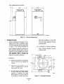
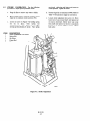
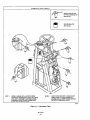
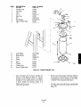
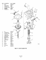
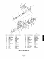
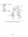
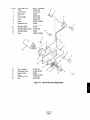
A typical Rosemount 8 x 14 Power
Positioner package should contain the items shown in
Figure l-l
1-3.
SYSTEM
OVERVIEW.
a. w.
This Instruction
Bulletin has been
designed to supply details needed to install,
operate, and service the Rosemount 8 x 14
Torque Type Power Positioner (Figure l-l). The
power positioner can be configured with optional
manual operator wheel, transfer valve, air lock,
bypass valve, supply air filter, clevis and dust
cover. Options for the power positioner include
electric position transmitter,
limit switches,
heater/thermostat and current to pneumatic (I/P)
converter.
b.
Power Positioner Features.
The fully featured
model 8 x 14 power positioner includes the
following features:
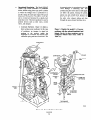
1. The manual operator wheel can be used by
the operator to manually change the position
of the device being controlled. In the event
of a power loss, continued operation of
power positioner is possible through manual
operator wheel.
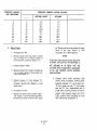
ITEM
1
2
3
DESCRIPTION
Model PP814T Power
Positioner
Air Filter
Instruction Bulletin
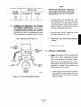
2. The transfer valve is a two position valve
that allows the operator to simultaneously
engage the air lock and manual operator, and
open the bypass valve. In the manual
position, air lock is engaged, manual
operator is engaged and bypass valve is
open. In automatic position, air lock is
disengaged, manual operator is disengaged
and bypass valve is closed.
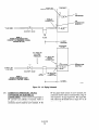
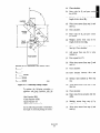
Figure 1-1. Typical System Package
l-2.
MODEL
NUMBER
MATRIX.
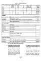
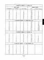
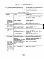
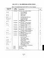
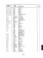
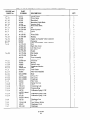
The PP814T has
a piston 8 inches in diameter and a maximum stroke
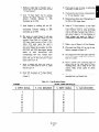
of 14 inches. Use model number matrix, Table l-l, to
verify your style number. The fust part of the matrix
defines the model. The last part defines the various
options and features of the power positioner. Copy
your model number from data plate located on back
of power positioner, compare this to Table l-l. Check
your code model number against the features and
options of the power positioner, making sure the
options specified by this number are on this unit. Use
this complete number for any correspondence with
Rosemount.
(a)
The air lock allows the operator to lock
the piston and output shaft assembly in
any position. This is done by moving
the transfer valve on top of the
positioner to the manual position.
When in the manual position, the
transfer valve C”ts off air pressure to
the air lock diaphragms, allowing the
fail-safe air lock to engage. When the
transfer valve is in the automatic
position, air pressure causes the air
lock diaphragms to disengage the air
lock.