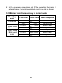
1
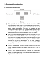
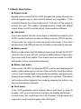
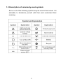
USER MANUAL
ONLINE UPS
PowerMust 1000E Online LCD (1K)
PowerMust 2000E Online LCD (2K)
PowerMust 3000E Online LCD (3K)
PowerMust 6000E Online LCD (6K)
PowerMust 10000E Online LCD (10K)
Thanks for your purchasing this product!
Safety instruction
Please read carefully the safety instructions
before you do anything to this product!
CONTENT
1. Product introduction......................................................................... 1
1.1 Functions description .................................................................... 1
1.2 Mode description ........................................................................... 2
1.3 Description of commonly used symbols........................................ 3
1.4 Front panel .................................................................................... 4
1.5 Rear panel ..................................................................................... 9
1.6 Product specification ................................................................... 12
1.7 Communication port .................................................................... 16
2. Installation........................................................................................ 17
2.1 Installation Safety Instructions .................................................... 17
2.2 Unpacking and Inspection ........................................................... 18
2.3 Installation steps for 1-3K standard model.................................. 19
2.4 Installation steps for 1-3K long back up time model ................... 19
2.5 Installation steps for 6-10K.......................................................... 20
2.6 Installation for communication software (optional)...................... 23
3.Operation........................................................................................... 24
3.1 Operation Safety Instructions...................................................... 24
3.2 Start the UPS with mains (AC source) ........................................ 25
3.3 Start the UPS with battery (DC source) only............................... 25
3.4 Connect loads to UPS ................................................................. 26
3.5 Charge the batteries.................................................................... 26
3.6 Discharge the batteries ............................................................... 27
3.7 Test the batteries ......................................................................... 27
3.8 Turn off the UPS with mains (AC source) ................................... 28
3.9 Turn off the UPS with battery (DC) only...................................... 28
3.10 Mute the buzzer......................................................................... 29
3.11 Operation in warning status....................................................... 29
3.12 Operation in fault mode............................................................. 29
3.13 Buzzer indication summary in normal mode............................. 30
4. Maintenance ..................................................................................... 31
4.1 Maintenance Safety Instructions ................................................. 31
4.2 Typical Trouble Shooting ............................................................. 33
4.3 Battery Maintenance ................................................................... 36
4.4 Contact the service center........................................................... 36
5.Transport and Storage ..................................................................... 37
1. Product introduction
1.1 Functions description
● This
product is a true online double-conversion UPS
(Uninterruptible Power Supply). It provides perfect protection for
critical load such as computer system. It can eliminate almost all
mains power disturbances. The input AC current can be
corrected to a wave following the mains voltage, so it is a high
power factor system. Through the PWM control technology, the
output voltage can be a pure & stable sine wave AC voltage.
● When the mains input become abnormal, the controller will stop
the AC/DC and start the DC/DC section immediately to make
sure the DC/AC (inverter) section can continue to work. After the
mains input comeback to normal range, the DC/DC will be
stopped and the AC/DC works again. So the load is always
power-supplied through inverter without any interrupt if the UPS
is turned on.
● The UPS also provides an internal bypass way to make the load
can be powered by mains input directly when the UPS is off or
failed.
● The UPS have an internal charger for batteries, the charger will
charge the batteries when the mains is in a reasonable range on
“bypass mode” or “line mode”.
1
1.2 Mode description
● Bypass mode
Bypass mode means that the UPS provides the power through the
internal bypass way to load directly without any regulation. If the
controller detects the mains is abnormal, it will shut off the output to
protect the load. The bypass voltage/frequency range and default
output status (on/off) could be set by communication software.
● Line mode
Line mode means that the mains input is rectified/converted by the
AC/DC section and then inverted to stable output by DC/AC section.
In line mode, the output is clean and good to the loads. If the mains
get abnormal, the UPS will transfer to battery mode without interrupt.
● Battery mode
Battery mode means that the battery power goes through the DC/DC
section to the inverter (DC/AC) and get a stable backup output when
the mains input is not usable. If the mains input recovered, the UPS
will transfer to line mode without interrupt.
● Battery test mode
In this mode, the UPS will stop the AC/DC section and discharge the
battery while mains input is normal. If the controller found the battery
is error, it will transfer back to line mode immediately, and warning by
display to see whether the battery needs to be replaced. The battery
test mode could be trigged in line mode by pressing the button or by
the communication command.
● Fault mode
If the UPS generates some internal failure and have to stop its
inverter, it will go into fault mode and alarm by display and buzzer.
In fault mode, the loads have the risk of power loss because the
output will come from the bypass after UPS fault.
2
1.3 Description of commonly used symbols
Some or all of the following symbols may be used in this manual. It is
advisable to familiarize yourself with them and understand their
meaning:
3
1.4 Front panel
1.4.1 Front view
1K/1KS
2K/2KS/3K/3KS
4
6KS/10KS
6K/10K
5
1.4.2 LCD display
(1) LCD icon description
Icon
Icon name
Description
Mains icon
It indicates the input is connected with mains, and
the input power is supplied from the mains.
Battery
It indicates the input is connected with battery,
and the input power is supplied from the battery.
Bypass
It indicates the UPS is in bypass mode, the load
current is directly from the utility power.
Inverter
It indicates that the load current is supplied from
utility power or battery via the inverter.
Fault
It indicates the UPS is in Fault mode.
Warning
It indicates the UPS has some warnings.
Data
Normally it indicates voltage/frequency value,
which are displayed alternately. If the UPS is in
fault, it indicates the fault code.
Battery level
It indicates the battery capacity. Every grid
represents the capacity of 25%. All the grids
turned on indicate the battery is full.
Load level
It indicates the load level. Every grid represents
the level of 25%. All the grids turned on indicate
the load is in 100% level.
6
(2) LCD display in different mode
LCD icon
Bypass mode (output disable)
●
●
Bypass mode (output enable)
●
●
Line mode
●
●
●
●
●
●
Battery mode
●
Battery test mode
●
★
Fault mode
◇
◇
◇
◇
Warning
□
□
□
□
●
●
●: Lightened constantly
★: Flashing
◇: Depended on the fault status
□: Depended on the original display
1.4.3 Button
There is only one button for ON/OFF/Mute function on this product. The
controller can distinguish the command according to the operation time
difference.
(1) Button action description
Button actions are distinguished with “short-press” and “long-press”.
Please refer to the following tables for the detail.
Button action type
Definition
Short-press
Press the button more than 0.04s and less than 0.5s
Long-press
Press the button more than 2s
Invalid press
Press the button more than 0.5s and less than 2s.
7
(2) UPS response to the button
Original
Button
mode
action
Long-press
Power off
UPS response
Turn on the UPS into battery mode.
The internal power supply is trigged for a short time
(cold status)
Other press
Bypass
Long-press
Turn on the UPS into line mode.
mode
Short-press
Mute the buzzer if there is a warning or alarming.
Long-press
Turn into bypass mode.
Short-press
Turn into battery test mode.
Battery
Long-press
Turn off the UPS.
mode
Short-press
Mute the buzzer.
Battery test
Long-press
Turn into bypass mode.
mode
Short-press
Turn into line mode.
Line mode
Long-press
Fault mode
Short-press
and then shutdown.
Turn into bypass mode or shutdown, dependent on
the fault type.
Change the beep status of buzzer.
8
1.5 Rear panel
1K
1KS
2K
2KS
9
3K
3KS
①/② Communication port (USB or RS232)
③ Mains input protection
④ Mains input power cord
⑤ Output socket
⑥ External battery terminal block
10
①/② Communication port (USB or RS232)
③ Mains input protection
④ AC input / output / External battery terminal block
⑤ Kickstand
11
1.6 Product specification
1.6.1 Model description
This manual is applicable to the following models:
Model
name
1K
1KS
2K
2KS
3K
3KS
6K
6KS
10K
10KS
Power
1000VA/700W 2000VA/1400W 3000VA/2100W 6000VA/4200W 10000VA/7000W
rating
Note: The model names without “S” represent standard model with
internal battery. The model names with “S” represent long backup time
model with external battery.
1.6.2 Environment specification
Model
1K
1KS
2K
2KS
3K
3KS
6K
6KS
10K
10KS
Operating
0-40°C
Temperature
Storage
0-40°C
Temperature
<1000m @ full load
<2000m @ 90%load
Altitude
<3000m @ 80%load
<4000m @ 70%load
Relative
<95%
Humidity
<50dB @ 1 meter from front
<55dB @ 1 meter from front
panel
panel
Noise Level
12
1.6.3 Mechanical Specification
1-3K
Model
1K
Dimension ((W×H×D) (mm)
Weight (Kg)
1KS
144x220x345
9.8
5.2
2K
2KS
190x318x369
20
10.8
3K
3KS
190x318x369
24.6
10.8
6-10K
Model
Dimension
6K
6KS
10K
10KS
200x735x 509 200x376x 509 200x735x 509 200x376x 509
(W×H×D) (mm)
Weight (Kg)
62
26
71
26
1.6.4 Electrical Specification
Model
1K
Power
1000VA/
700W
1KS
2K
2KS
2000VA/
1400W
3K
3KS
3000VA/
2100W
6K
6KS 10K 10KS
6000VA /
4200W
10000VA /
7000W
Input
Current (Max.)
5A
6A
10A
11A
15A
16A
30A
32A
47A
Voltage Range 176~276VAC @ full load (110~276VAC @ half load)
Frequency
Range
46 ~ 54Hz @ 50Hz system / 56 ~ 64Hz @ 60Hz system
Input Power
Factor
≧0.98 @ full load
Output
Voltage
208/220/230/240VAC (sine-wave)
Synchronizing mains input @ line mode
Frequency
50/60Hz ± 0.2 Hz @ battery mode
13
50A
THD
≦4% ( Linear load )
Voltage
Regulation
± 2%
Overload
Line mode: 60s @ 100%~130%; 1s @ > 130%
Capacity
Battery mode: 10s @ 100%~130%; 1s @ >130%
Efficiency
Line Mode
86%
Battery Mode
80%
89%
83%
83%
24
48
72
VDC
VDC
VDC
84% 89% 88% 89%
Battery & Charger @ 25℃
Total battery
rating voltage
144
240
192
240
VDC VDC VDC VDC
Backup Time
>9min
>9min
>9min
>9min
>8min
5
5
5
5
5
Hours
Hours
Hours
Hours
Hours
(Half Load)
Recharge Time
(to 90%)
Charging Current
1A
4A
1A
4A
1A
4A
1A
4A
1A
4A
(Max.)
Discharging
44A
42A
42A
Rated Charging
27.3
54.6
81.9
Voltage
Vdc
Vdc
Vdc
24A
39A
Current (Max.)
14
163.8 273 218.4 273
Vdc
Vdc
Vdc
Vdc
1.6.5 Standards
1-3K
* Safety
IEC/EN 62040-1-1
* EMI
Conducted Emission.......................................:IEC/EN 62040-2
Category C1
Radiated Emission......................................... :IEC/EN 62040-2
Category C1
Harmonic Current............................ :IEC/EN 61000-3-2 (Input Current≤16A)
Voltage Fluctuation and Flicker........ :IEC/EN 61000-3-3 (Input Current≤16A)
*EMS
ESD............................................................. :IEC/EN 61000-4-2
Level 4
RS............................................................... :IEC/EN 61000-4-3
Level 3
EFT.............................................................. :IEC/EN 61000-4-4
Level 4
SURGE....................................................... :IEC/EN 61000-4-5
Level 4
CS............................................................... :IEC/EN 61000-4-6
Level 3
Power-frequency Magnetic field.................. :IEC/EN 61000-4-8
Level 3
Low Frequency Signals............................. :IEC/EN 61000-2-2
6-10K
* Safety
IEC/EN 62040-1-1
* EMI
Conducted Emission....................................:IEC/EN 62040-2
Radiated Emission.......................................:IEC/EN 62040-2
Category C3
Category C3
*EMS
ESD......................................................... :IEC/EN 61000-4-2
RS............................................................ :IEC/EN 61000-4-3
EFT.......................................................... :IEC/EN 61000-4-4
Level 4
Level 3
Level 4
SURGE.................................................... :IEC/EN 61000-4-5
CS............................................................ :IEC/EN 61000-4-6
Power-frequency Magnetic field.............. :IEC/EN 61000-4-8
Low Frequency Signals.......................... :IEC/EN 61000-2-2
Level 4
Level 3
Level 3
Warning: This is a product for commercial and industrial application in the
second environment-installation restrictions or additional measures may be
needed to prevent disturbances.
15
1.7 Communication port
The communication port is for the monitoring software. There are 2
options: RS232 or USB. There is only one option can work in the same
time and same product.
1) RS232 (optional)
Pin assignment and description of DB-9 connector:
Pin#
Definition
2
TXD (output)
3
RXD (input)
5
GND
2) USB (optional)
The USB port is compliance with USB 1.1 protocol for its communication
software.
16
2. Installation
2.1 Installation Safety Instructions
You must read the following safety instructions before
installation!
● Installation Personnel
This product must be installed only by qualified or
professional personnel accord to safety
● Installation Environment
Do not install and operate the UPS when water
condensation happen which may occur if the UPS is moved directly
from a cold to a warm environment. The UPS must be absolutely dry
before being installed and operated. Please allow an acclimatization
time of at least 2 hours. Otherwise there is hazard of electric shock!
Do not install the UPS in the environment where it is damp
or would be exposed to direct sunlight or near heat. Ensure the UPS
is far away from water, inflammable gas and corrosive agents.
Do not block air vents in the housing of UPS. The UPS
must be installed in a location with good ventilation. Ensure enough
space on each side for ventilation.
17
● Wiring & Grounding
Installation and Wiring must be performed in accordance with
the local electrical laws and regulations.
The UPS must be securely grounded. If there are external
UPS battery cabinets, please make sure the battery cabinets have the
equipotential earth bonding to the UPS main cabinet.
An appropriate switch device as backup protection for
over-current or short-circuit should be provided in the input utility.
● Battery
Strictly follow the principle of “same voltage, same type” when
paralleling multi battery packs.
DC breaker or fuse must be used as a protection device
between the external battery pack and the UPS. The spec of
protection must be matched to the UPS specification.
2.2 Unpacking and Inspection
2.2.1 Unpack the package and check the contents. The shipped
package contains:
●
1 UPS
●
1 user manual
2.2.2 Inspect the appearance of the UPS to see if there is any damage
during transportation. Do not turn on the unit and notify the
dealer immediately if there is any damage or lack of some parts.
18
2.3 Installation steps for 1-3K standard model
1) Make sure the wire / circuit breaker / socket are enough for the current
rating of UPS to avoid the hazards of electric shock and fire.
2) Make sure the mains switch in the building is cut off.
3) Make sure the UPS is not be turned on before wiring operation.
4) Turn off all load switches first before connecting the load to the UPS.
5) Make sure the protective earth ground is correct.
6) Connect the loads to the UPS through the outlet sockets.
7) Connect the input power cord of UPS to mains.
2.4 Installation steps for 1-3K long back up time model
1) Make sure the wire / circuit breaker / socket are enough for the
power rating of UPS to avoid the hazards of electric shock and fire.
2) Make sure the mains switch in the building is cut off.
3) Turn off all load switches first before connecting the load to the UPS.
4) Make sure the protective earth ground is correct.
5) Install the external battery as following:
● Warning: Make sure the mains input have been cut off.
● Switch off the battery breaker if there is a battery breaker.
● Remove the cover of external battery terminal of UPS.
● Warning: Pay highly attention to the rating battery voltage
marked on the rear panel, the connection with wrong battery
voltage may cause permanent damage of the UPS.
● Warning: Pay highly attention to the polarity marking on external
battery terminal block, and make sure the correct battery polarity
is connected. Wrong connection may cause permanent damage
of the UPS.
19
● Prepare the external battery cable that should be able to carry
the current of >50A, the cross section area should be greater
than 5.26 mm 2. It is recommended to use 8 AWG wire or thicker
for safety and efficiency. And battery wire color is recommended
as following:
+
GND
-
Red wire
Yellow/Green wire
Black wire
● Connect the GND pole of external battery terminal block on the
rear panel of UPS to the earth point of battery pack.
Note: Always connect the earth wire first!
● Connect the Positive (+) pole of external battery terminal block
on the rear panel of UPS to the Positive polarity of battery pack;
● Connect the Negative (-) pole of external battery terminal block
on the rear panel of UPS to the Negative polarity of battery pack.
● Check the wiring and voltage of the battery pack. Make sure the
polarity and voltage is correct.
● Install the terminal block cover on the rear panel of the UPS.
6) Connect the loads to the UPS through the outlet sockets.
7) Connect the input power cord of UPS to mains.
2.5 Installation steps for 6-10K
1) Make sure the mains wire & breakers in the building are enough for
the rating of UPS to avoid the hazards of electric shock and fire.
Note: Do not use the wall receptacle as the input power source for
the UPS, as its rated current is less than the UPS’s maximum input
current. Otherwise the receptacle may be burned and destroyed.
2) Cut off the mains switch in the building before installation.
3) Turn off all the load switches before connect the load to the UPS.
20
4) Prepare wires according to the following table:
Wiring spec (AWG)
Model
Input
Output
6K
12
12
6KS
12
12
10K
9
9
10KS
9
9
Battery
Ground
12
12
12
9
9
9
Note 1: The cable for 6K/6KS should be able to carry the current of
>40A, the cross section area should be greater than 3.31 mm 2. It is
recommended to use 12 AWG wire or thicker for safety and
efficiency.
Note 2: The cable for 10K/10KS should be able to carry the current
of >60A, the cross section area should be greater than 6.63 mm 2. It
is recommended to use 9 AWG wire or thicker for safety and
efficiency.
Note 3: The color of wires should be selected according to the local
electrical laws and regulations.
5) Remove the terminal block cover on the rear panel of UPS. Then
connect the wires according to the following terminal block
diagram: (Always connect the earth wire first!)
Wiring connection on the 6K/10K rear panel
21
Wiring connection on the 6KS/10KS rear panel
Warning: (Only for standard model)
●
Make sure the UPS is not turned on before installation. The UPS
must not be turned on when doing wiring operation.
●
Do not try to modify the standard model to the long back up time
model. Especially do not try to connect the standard internal battery
to the external battery. The battery type and voltage may be different.
If you connect them together, it maybe causes the hazard of electric
shock or fire! The standard model and long back up time model are
differently designed according to different battery voltage and
thermal solution.
Warning: (Only for long back up time model)
●
Make sure a DC breaker or other protection device between UPS and
external battery pack is installed. If not, please install it carefully. Switch
off the battery breaker before installation.
●
Pay highly attention to the rating battery voltage marked on the rear
panel, the connection with wrong battery voltage may cause
permanent damage of the UPS. Make sure the voltage of the
battery pack is correct.
●
Pay highly attention to the polarity marking on external battery
terminal block, and make sure the correct battery polarity is
22
connected. Wrong connection may cause permanent damage of the
UPS.
●
Make sure the battery input wiring is correct before power on. The
wire current spec, color, position, connection and conductance
reliability should be checked carefully. Make sure the +/- polarity is
correct, not reverse, no short circuit.
●
Make sure the protective earth ground wiring is correct. The wire
current spec, color, position, connection and conductance reliability
should be checked carefully.
Make sure the mains input & output wiring is correct. The wire
current spec, color, position, connection and conductance reliability
should be checked carefully. Make sure the L/N site is correct, not
reverse, no short circuit.
● Install the terminal block cover on the rear panel of the UPS
●
2.6 Installation for communication software (optional)
1) Connect the communication cable between UPS and PC. If the port
is RS232, please lock the secure screw both on UPS and PC after
connection. If the port is USB, it has Plug and Play function.
2) Please refer to the guide manual of software or contact the service
center for installation and operation of management (monitoring)
software.
23
3.Operation
3.1 Operation Safety Instructions
You must read the following safety instructions before
operation!
● operation personnel
Laymen can operate this product.
● operation warning
Do not disconnect the earth conducting wire on the UPS or the
building wiring terminals in any time since this would cancel the
protective earth of the UPS system and all connected loads.
Do not try to disassemble the original part of the UPS before
turn off and disconnect it from the mains power & external battery.
The UPS output socket may be electrically lived even if the
UPS system is not connected to the mains power source.
Do not make any liquid and foreign objects enter the UPS.
Turn off the mains input switch and external battery switch
immediately at any accident of electric shock and fire related to the UPS.
24
3.2 Start the UPS with mains (AC source)
1) If the UPS is a long back up time model, with external battery banks,
please switch on the battery breaker first;
2) If the wiring is correct, turn on the mains breaker in your building.
Then the power supply inside the UPS will be started automatically,
the fans will run, and the panel will display with bypass mode.
Note 1: If the UPS have been set to enable the bypass output, the
output socket will have the voltage directly from mains after you turn
on the input breaker.
Note 2: In bypass mode, the load is not protected by UPS. You
should go on to the next step to turn on the UPS for protecting your
load.
3)
Press the button on the front panel of the UPS continuously for more
than 2 seconds. The buzzer will beep once. After a few seconds of
self-diagnoses, the UPS will be turned on to the normal mode (line
mode) and output the spec voltage.
4)
After the UPS is turned on to line mode normally, the panel will
display line mode, and there is no beep of buzzer.
Note: If the UPS is shutdown in battery mode automatically, and when
the mains power returned to the input, the UPS will start up and switch
to line mode automatically.
3.3 Start the UPS with battery (DC source) only
This UPS can be started with DC source (battery) without AC source.
1) If the UPS is a long back up time model with external battery banks,
please switch on the battery breaker first.
2) Press the button on the front panel of the UPS continuously for more
than 2 seconds. The buzzer will beep once. After a few seconds of
self-diagnoses, the UPS will be turned on to the battery mode and
output the spec voltage.
25
3) After the UPS is turned on to battery mode normally, the panel will
display battery mode, and the buzzer will beep according to the
battery level.
3.4 Connect loads to UPS
After the UPS is turned on, you can switch on the loads.
1) It is recommended to switch on the load one by one. The panel will
display the load level.
2) If it is necessary to connect the inductance load such as a printer to
the UPS, the start-up power should be considered for calculating the
capacity of the UPS, because the power consumption is too big
when this kind of load is started.
3) If the UPS is overloaded, all the load level grids indicator will flash
and the warning indicator will lighten constantly. The buzzer will
beep twice every second for alarming.
4) If the UPS is overloaded, some loads must be switched off or
decreased immediately. It is recommend that the total loads
connected to the UPS had better be less than 80% of its nominal
power capacity to prevent the overload happen at the transient time,
and it will make your system more safe.
5) If the overload time is over spec in line mode, the UPS will transfer to
bypass, after the overload disappears, it will return to line mode. If
the overload time is over spec in battery mode, the UPS will cut off
the output and then shutdown according to the battery level.
3.5 Charge the batteries
1) After the UPS is connected to normal mains, the charger will work and
charge the batteries automatically in bypass mode or line mode.
2) Suggest charging the batteries for 10 hours before use. Otherwise
the backup time may be less than the standard value.
26
3.6 Discharge the batteries
1)
When the UPS is in battery mode, the buzzer will beep according to
different battery level. If the battery level is normal, the buzzer will
beep once every 4 seconds; If the battery voltage drops to the
alarming level, the buzzer will beep hurry (once every sec) to
remind the user that the battery is low level and the UPS will be
shutdown automatically soon. The user could switch off some
non-critical loads to avoid the shutdown alarming and prolong the
backup time. If have no more load to be switched off at that time,
you have to shutdown all loads as soon as possible to protect the
loads or save data. Otherwise there is the risk of data loss or load
failure.
2) In battery mode if the user don’t like the buzzer noise, the beep
could be muted by short-press the button.
3) The backup time of the long backup time model is dependent on the
external battery capacity except the load capacity mainly.
4) The backup time may vary from different environment temperature
and load type.
3.7 Test the batteries
1) If you need to check the battery level or aging status when the UPS
is running on normal mode (line mode), you could short-press the
button to let the UPS transfer to battery test mode.
2) To make the system more reliable, the UPS will perform the battery
test automatically periodically. The default period is once per week.
3) The battery test could be performed by the command from monitoring
software through the communication port.
4) If the UPS enter the battery test mode, the display and buzzer
indication will be the same as the battery mode except that the
Battery icon is flashing and the mains icon lighten constantly. So you
can check the battery level at this mode.
27
3.8 Turn off the UPS with mains (AC source)
1)
Firstly turn off the UPS (inverter) to bypass mode, please press the
button continuously for more than 2 seconds.
2) After you press the button, the buzzer will beep once. Then the
panel will display bypass mode.
Note 1: If the UPS have been set to enable the bypass output, the
output socket will have voltage from mains directly after you turn off
the UPS (inverter) to bypass mode.
Note 2: Because there is risk of power loss for the loads if you turn
off the UPS to bypass mode, please make sure the loads are
prepared for your operation.
3) If you want to turn off the output of UPS and shut down the UPS
completely, you have to cut off the mains input of UPS.
Note: please make sure all the loads are prepared or turned off for
your operation before you shutdown the UPS system.
4) After you cut off the mains input of UPS to shut down, the
background lighting is still on but all the icons are turned off to
indicate that the UPS is saving data to the memory. After the saving
process, the UPS will be shutdown completely.
3.9 Turn off the UPS with battery (DC) only
1) To turn off the UPS in battery mode, please press the button
continuously for more than 2 seconds.
2) After you press the button, the buzzer will beep once, the
background lighting is still on but all the icons are turned off to
indicate that the UPS is saving data to the memory. After the saving
process, the UPS will be shutdown completely.
Note: please make sure all the loads are prepared or turned off for
your operation before you shutdown the UPS system.
28
3.10 Mute the buzzer
1) To mute the buzzer, please short-press the button. If you short-press
it again after the buzzer muted, the beep will be returned.
2) It is not anytime the buzzer can be muted. If it is in warning/batterylow/overload, the buzzer can’t be muted unless the trouble is solved.
3) If it is in fault mode, short-press the button could transfer the
continuous beep to once-every-second.
3.11 Operation in warning status
1) In case the LCD background lighting is flashing once every 4
seconds, and the buzzer is beeping once every second, it shows
that there are some troubles, please check the troubleshooting table
in chapter 4 to find out what happen to the UPS. At this time, the
warning indicator will be turned on constantly, the user can
short-press the button to stop the background lighting flashing and
turn on it for 1minute to see the warning status.
2) If the warning happens, the UPS will continue work in the original
mode, the operation will not be interrupted. If the error is corrected,
the warning alarm will stop.
3.12 Operation in fault mode
1) In case the LCD background lighting is flashing once every second
and the buzzer is beeping continuously, it shows that there must be
a fatal error in the UPS and it is operating in abnormal mode. At this
time, the Fault indicator will be turned on constantly with the fault
code displaying in the data section .The user can short-press the
button to stop the background lighting flashing and turn on it for
1minute to see the fault code.
2) If fault happens, please notes and record what the display shows,
the display information is very important for the trouble shooting.
Please refer to the trouble shooting table in chapter 4 for detail.
3) Please check your loads, wiring, ventilation, mains, battery and so
on after the fault happens. Don’t try to turn on the UPS again before
find out the reason. If the trouble can’t be shoot, please contact the
distributor or service people.
29
4) In the emergency case, please cut off the connection from mains /
external battery / output immediately to avoid more risk or danger.
3.13 Buzzer indication summary in normal mode
Operating
mode
Line mode
Bypass mode
Battery mode
/ Battery test
mode
Load level
Battery level
Buzzer beep once
0~100%
None
>100%
Every 0.5 sec
0~100%
Every 2 min
>100%
Every 0.5 sec
0~100%
0~25%
Every sec
0~100%
25%~100%
Every 4 sec
>100%
Every 0.5 sec
30
4. Maintenance
4.1 Maintenance Safety Instructions
You must read the following safety instructions before
maintenance!
● Maintenance Personnel
This product must be maintained only by qualified
professional personnel accord to safety instructions!
● Risk of electric shock
No matter the UPS is connected to the utility power or not, the
output may have electricity. The parts (battery, capacitor) inside the
unit may still have hazardous voltage after turning off the UPS.
Make sure to disconnect the batteries before carrying out any
kind of maintenance or repair. In this product, the battery is dangerous.
Verify that no voltage between the battery terminals and the
ground is present before maintenance or repair. In this product, the
battery circuit is not isolated from the input voltage. Hazardous
voltages may occur between the battery terminals and the ground.
Verify that no hazardous voltage exists in the energy storage
capacitor before maintenance or repair.
31