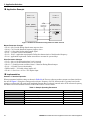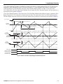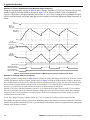
1
YASKAWA AC Drive-A1000 Traverse Application Custom Software Supplement Software Number: VSA91019□ Drive Models: AU□A□□□□□□□ To properly use the product, read this manual thoroughly and retain for easy reference, inspection, and maintenance. Ensure the end user receives this manual. MANUAL NO. TM.A1000SW.029 Table of Contents 1 2 3 PREFACE AND SAFETY . . . . . . . . . . . . . . . . . . . . . . . . . . . . . . . . . . . . . . . . . . . 5 PRODUCT OVERVIEW . . . . . . . . . . . . . . . . . . . . . . . . . . . . . . . . . . . . . . . . . . . . 6 APPLICATION SELECTION . . . . . . . . . . . . . . . . . . . . . . . . . . . . . . . . . . . . . . . . 7 Refer to the A1000 Technical Manual for content not described in this document. Copyright © 2013 YASKAWA ELECTRIC CORPORATION All rights reserved. No part of this publication may be reproduced, stored in a retrieval system, or transmitted, in any form or by any means, mechanical, electronic, photocopying, recording, or otherwise, without the prior written permission of Yaskawa. No patent liability is assumed with respect to the use of the information contained herein. Moreover, because Yaskawa is constantly striving to improve its high-quality products, the information contained in this manual is subject to change without notice. Every precaution has been taken in the preparation of this manual. Yaskawa assumes no responsibility for errors or omissions. Neither is any liability assumed for damages resulting from the use of the information contained in this publication. YASKAWA TM.A1000SW.029 Traverse Application A1000 Custom Software Supplement 3 This Page Intentionally Blank 4 YASKAWA TM.A1000SW.029 Traverse Application A1000 Custom Software Supplement 1 Preface and Safety 1 Preface and Safety Yaskawa manufactures products used as components in a wide variety of industrial systems and equipment. The selection and application of Yaskawa products remain the responsibility of the equipment manufacturer or end user. Yaskawa accepts no responsibility for the way its products are incorporated into the final system design. Under no circumstances should any Yaskawa product be incorporated into any product or design as the exclusive or sole safety control. Without exception, all controls should be designed to detect faults dynamically and fail safely under all circumstances. All systems or equipment designed to incorporate a product manufactured by Yaskawa must be supplied to the end user with appropriate warnings and instructions as to the safe use and operation of that part. Any warnings provided by Yaskawa must be promptly provided to the end user. Yaskawa offers an express warranty only as to the quality of its products in conforming to standards and specifications published in the Yaskawa manual. NO OTHER WARRANTY, EXPRESS OR IMPLIED, IS OFFERED. Yaskawa assumes no liability for any personal injury, property damage, losses, or claims arising from misapplication of its products Applicable Documentation The following manuals are available for the A1000 Drive: SUPPLEMENT Custom Software Supplement Yaskawa AC Drive - Traverse Application A1000 Custom Software Supplement Manual No: TM.A1000SW.029 Read this manual first. This supplement is an addendum to the A1000 Quick Start Guide and Technical Manual. It lists the effects of this custom software on the parameters in the drive and function descriptions in the manual. To obtain the supplement access this site: U.S: http://www.yaskawa.com Yaskawa Drive Yaskawa AC Drive A1000 Quick Start Guide Yaskawa AC Drive A1000 Technical Manual To obtain instruction manuals for Yaskawa products access these sites: U.S.: http://www.yaskawa.com Europe: http://www.yaskawa.eu.com Japan: http://www.e-mechatronics.com Other areas: contact a Yaskawa representative. For questions, contact the local Yaskawa sales office or the nearest Yaskawa representative. Supplemental Safety Information Read and understand this manual and the A1000 Quick Start Guide before installing, operating, or servicing this option unit. Install the drive according to the A1000 Quick Start Guide and local codes. Observe all cautions and warnings in this document and the standard drive technical manuals. Refer to the A1000 Quick Start Guide and Technical Manual for safety information and to install and start-up the drive. This document is a supplement to the standard drive technical manual. It describes the effects on the drive parameters and functions with the software installed. • Custom software is provided to add functionality to a standard drive to enhance or enable use in a specific application. • The software is loaded to the flash ROM area of the control board, and replaces the standard drive software. Obtaining Support When seeking support for a drive with custom software, it is imperative to provide the unique part number shown on the drive nameplate. The software is flashed to the control board memory and the operation of parameters, functions, and monitors are different than the standard drive software, as described herein. Refer to Yaskawa office locations listed on the back cover of this manual. YASKAWA TM.A1000SW.029 Traverse Application A1000 Custom Software Supplement 5 2 Product Overview 2 Product Overview About This Product This custom software is designed specifically for use in Traverse applications. Applicable Models This custom Traverse application software is available for the A1000 drive models listed in Table 1. Table 1 Applicable Models Voltage Class 200 V Three-Phase 400 V Three-Phase 600 V Three-Phase Models AU2A0004F to 2A0211F, AU2A0250A to 2A0415A AU4A0002F to 4A0165F, AU4A0208A to 4A0675A AU5A0003F to 5A0099F, AU5A0125A to 5A0242A Software Version <1> VSA91019 VSA91019 VSA91019 <1> See “PRG” on the drive nameplate for the software version number. 6 YASKAWA TM.A1000SW.029 Traverse Application A1000 Custom Software Supplement 3 Application Selection 3 Application Selection Traverse Anti-Phase Overview The Traverse Anti-Phase function controls the traverse arm of a winder in textile industry applications. This function generates a dithered disturbed waveform that is used as frequency reference for the traverse arm drive and also provides an anti-phase signal for output to a spindle slave drive for better winding. Basic Concept When the drive reaches the set frequency reference, the output frequency waveform is modulated in a triangle type pattern. This randomizes fiber overlap on the spindle, producing a tighter wrap and a higher quality wound package. P1 parameters are used to set the attributes of a disturbed waveform, which is essentially a triangle wave with instantaneous jumps at the peak and trough. This triangle wave rides on top of the base frequency reference for the traverse drive. The signal(s) output to control the slave spindle drive can be set to one of three new monitors: • U7-02 - Absolute Slave Frequency • U7-03 - Ripple Slave Frequency • U7-04 - Slave Base Frequency The Absolute and Ripple Slave Frequency monitors have an anti-phase component to them, outputting a disturbed waveform that is the inverse (anti-phase) of the master disturbed waveform. The anti-phase waveform ignores the jump portion of the master traverse disturbed waveform. Limitations • The following languages are supported: English, Japanese, Spanish, German, French, Italian, and Portuguese. • Parameter L4-02, Speed Agree Detection Width, should be set to a small, nonzero value to avoid unintended jumps in the disturbed waveforms. • When P1-04 and P1-05 are set to short slope times, set L4-02 to a value greater than 0.5 Hz to prevent inconsistent traverse operation. • Step changes in frequency reference will result in unintended jumps in the disturbed waveforms. Disable the Traverse function using the 80h (Disturbed WF Off) digital input to prevent damage to the motor or connected equipment. • The Traverse waveform can be configured to be smaller than the input resolution of the A1000 slave drive's frequency reference. Ensure that Master Frequency Reference × P1-02 is significantly larger than (Slave Max Output Freq/2048) for proper control of the slave drive. YASKAWA TM.A1000SW.029 Traverse Application A1000 Custom Software Supplement 7 3 Application Selection Control Modes, Symbols, and Terms The table below lists terms and symbols used in this section to indicate which parameters are available in which control modes. Description All Modes V/f V/f w PG 8 Parameter is available in all control modes. Parameter is available when operating the drive with V/f Control. Parameter is available when operating the drive with V/f with PG Control. OLV Parameter is available when operating the drive with Open Loop Vector. CLV OLV Parameter is available when operating the drive with Closed Loop Vector. V/f w PG OLV/PM Parameter is available when operating the drive with Open Loop Vector for PM monitors. V/f w PG AOLV/PM Parameter is available when operating the drive with Advanced Open Loop Vector for PM monitors. CLV/PM Parameter is available when operating the drive with Closed Loop Vector for PM monitors. YASKAWA TM.A1000SW.029 Traverse Application A1000 Custom Software Supplement 3 Application Selection Related Parameters and Functions The following parameters are used to set up the drive for operation with the software. Available parameter settings are listed based upon which drive control modes are active, as listed in the Control Mode Access Level column in the following tables. Confirm proper setting of the parameters beginning with Table 2. Table 2 Modified Parameters No. (Addr. Hex) Parameter Name Digital Operator Display A1-00 Language Selection (100h) Select Language Description Values 0: English 1: Japanese 2: German 3: French 4: Italian 5: Spanish 6: Portuguese Default: 0 Range: 0 to 6 Change during Run Control Mode Access Level No All Modes Table 3 Additional Parameters No. (Addr. Hex) P1-01 (600h) P1-02 (601h) P1-03 (602h) P1-04 (603h) P1-05 (604h) P1-06 (605h) Parameter Name Digital Operator Display Disturbed Waveform Selection Disturb WF Sel Disturbed Waveform Amplitude Disturb WF Amp Disturbed Waveform Jump Disturb WF Jmp Negative Slope Time Neg Slope Time Positive Slope Time Pos Slope Time Slave Scan Offset Slv Scan Offset Description Values Enables and disables the traverse disturbed waveform function. 0: Disabled 1: Enabled Sets the amplitude of the disturbed waveform as a percentage of the commanded frequency reference. Note: Setting this parameter to 0.0 disables the Transverse function. Adds a notch or jump below the peak amplitude of the disturbed waveform when set to a non-zero value. Set as a percentage of the Disturbed Waveform Amplitude (P1-02). Sets the time for the disturbed waveform to decelerate from the maximum value (reference + P1 02) to the minimum value (reference - P1-02). Note: Setting this parameter to 0.0 seconds disables the Transverse function. Sets the time for the disturbed waveform to accelerate from the minimum value (reference - P1 02) to the maximum value (reference + P1-02). Note: Setting this parameter to 0.0 seconds disables the Transverse function. Monitor shift (U7-02, U7-03, and U7-04) in ms to compensate for systematic delays. Default: 0 Range: 0 to 1 Change during Run Control Mode Access Level Yes OLV V/f OLV/PM Default: 0.0 Range: 0.0 to 20.0 % V/f Yes OLV OLV/PM Default: 0.0 Range: 0 to 50.0% V/f Yes OLV OLV/PM Default: 0.0 Range: 0.0 to 120.0 s V/f Yes OLV OLV/PM Default: 0.0 Range: 0.0 to 120.0 s V/f Yes OLV OLV/PM Default: 0 ms Range: -24 ~ 24 ms V/f Yes OLV OLV/PM Table 4 Group Text Group Name Digital Operator Display Function Group P Traverse Group Traverse YASKAWA TM.A1000SW.029 Traverse Application A1000 Custom Software Supplement 9 3 Application Selection Table 5 Function Text Function Name Digital Operator Display Function Group P1 Disturbed Waveform Adjustment Disturb WF Adj Table 6 Monitor Function Text Monitor Name Digital Operator Display Function Group U7 Traverse Monitors Traverse Table 7 Monitors No. (Addr. Hex) Monitor Name Digital Operator Display U7-02 Absolute Slave Frequency (661h) Slv Abs Freq U7-03 Ripple Slave Frequency (662h) Slv Ripple Freq U7-04 Base Slave Frequency (663h) Slv Base Freq Description Base frequency reference summed with the anti-phase dither. Analog Output Scaling 10V: Maximum Frequency (E1-04) 10V: Maximum Frequency (E1-04) Anti-phase dither alone. Base frequency reference (before disturbed waveform is applied). 10V: Maximum Frequency (E1-04) Unit Control Mode Access Level 0.01 Hz OLV V/f OLV/PM V/f 0.01 Hz OLV OLV/PM V/f 0.01 Hz OLV OLV/PM Table 8 Multi-function Input Settings (H1-) Setting 80h Description Disturbed WF Off Open: Disturbed waveform enabled Closed: Disturbed waveform disabled Control Mode Access Level V/f OLV OLV/PM Table 9 Multi-function Output Settings (H2-) Setting 40h 41h 10 Description Disturb UP Sts Open: The disturbed waveform frequency is decreasing Closed: The disturbed waveform frequency is increasing During Disturb Open: Disturbed waveform disabled Closed: Disturbed waveform being generated Control Mode Access Level V/f OLV OLV/PM V/f OLV OLV/PM YASKAWA TM.A1000SW.029 Traverse Application A1000 Custom Software Supplement 3 Application Selection Function Description Machine Parameter Selection The disturbed waveform begins once the drive reaches Speed Agree. The disturbed waveform rides on top of the base frequency reference for the traverse drive. The output will be the frequency reference waveform summed with the disturbed waveform if the frequency reference of the master drive is adjusted while the disturbed waveform is active. The dithering is a triangle waveform with amplitude and slope set by P1-02, P1-04, and P1-05 parameters. The traverse drive also has a jump in the dithering wave form which is set by parameter P1-03. The anti-phase output signal is the disturbed portion of the traverse frequency reference signal inverted. Only the triangle portion of the disturbed waveform is used for the anti-phase. The jump is ignored. The Traverse application software has three monitors: • Base Slave Frequency (U7-04) U7-04, Base Slave Frequency, outputs the frequency reference of the master (traverse) before the disturbed waveform is applied. • Ripple Slave Frequency (U7-03) U7-03, Ripple Slave Frequency, outputs the anti-phase of the disturbed portion of the waveform. • Absolute Slave Frequency (U7-02) U7-02, Absolute Slave Frequency, outputs the anti-phase of the disturbed portion of the waveform summed with U7-04. To compensate for system delays, U7-02, U7-03, and U7-04 monitors can be set to lead or lag the traverse control output by up to 24 scans (24 ms), set by P1-06. All three monitors can be set to analog outputs. U7-02 or U7-03 would generally be used as an analog output going to the slave (spindle) for its frequency reference. U7-02 provides the slave a complete reference signal. U7-03 is used as a dither reference if the slave is to use its own base frequency reference as shown in Figure 1. YASKAWA TM.A1000SW.029 Traverse Application A1000 Custom Software Supplement 11 3 Application Selection Application Example Figure 1 H2-01 = 41 H1-08 = 7 H4-01 = 703 H3-09 = 1 + A 1000 (Master) Traverse Software Slave Frequency Reference A1 A1000 (Slave) Standard Software - FM A2 DIP Switch S1 AC AC MA S8 MC SC V I Figure 1 Software and Hardware Configuration for A1000 Traverse Master Parameter Changes • • • • • • H2-01 = 41h: Provide during disturb status output to slave. H4-01 = 703: Provide disturbed frequency ripple to slave. H4-07 = 1: Provide a bipolar analog output signal. P1-01 = 1: Enable Traverse functionality. P1-02 ~ P1-05 = application requirements: Define the characteristics of the disturbed frequency. P1-06 = application requirement: Define scan offset to account for system delays. Slave Parameter Changes • • • • • • C1-03 = 0.0 sec: Set acceleration time 2 to 0.0 seconds. C1-04 = 0.0 sec: Set deceleration time 2 to 0.0 seconds. H1-08 = 7: Switch between accel/decel time 1/2 based on During Disturb output. P1-01 = 1: Enable Traverse functionality. DIP Switch S1 = V: Enable voltage input to A2. H3-09 = 1: Set A2 to a -10V to +10V bipolar input. Implementation Situation 1: Standard Operation When programmed with the settings as shown in Table 10, the Traverse software produces output waveforms similar to the ones in Figure 2. Using these settings and a reference frequency of 45 Hz, the master drive operates based on the triangle waveform with 9 Hz (peak-peak) amplitude. Because the waveform is centered on the 45 Hz reference frequency, the master waveform oscillates between 36 and 54 Hz while in Traverse mode. Table 10 Sample Operating Parameters Parameter P1-01 P1-02 P1-03 P1-04 P1-05 P1-06 12 Name Disturbed Waveform Selection Disturbed Waveform Amplitude Disturbed Waveform Jump Negative Slope Time Positive Slope Time Slave Scan Offset Setting 1 20.0% 50.0% 5.0 s 4.0 s 0 ms YASKAWA TM.A1000SW.029 Traverse Application A1000 Custom Software Supplement 3 Application Selection U7-02, Slave Absolute Frequency, (available as an output to the slave by setting parameter H4-01 to 702), has the same amplitude of 9 Hz (calculated by P1-02 × Reference Frequency). U7-02 is anti-phase to the master waveform and is centered around U7-04, the Slave Base Frequency. Since the Slave Base Frequency is 45 Hz, U7-02 varies from 36 to 54 Hz while in Traverse mode. Before entering Traverse mode, the Slave Absolute Frequency will rest at 48 Hz, as represented by the equation in Figure 2. U7-03, Slave Ripple Frequency, is the same as the U7-02 waveform without the Slave Base Frequency component. Slave Ripple Frequency U7-03 is a bipolar waveform centered at 0 Hz. The output varies from 21 to 39 Hz during operation. The Slave Ripple Frequency will rest at 3 Hz before entering Traverse mode as represented by the equation in Figure 2. Figure 2 Run Command P1-02 x Freq Ref P1-02 x Freq Ref x P1-03 Frequency Reference P1-02 x Freq Ref P1-04 P1-02 x Freq Ref x P1-03 P1-05 0 Hz U7-02 Slave Absolute Frequency P1-02 x Freq Ref x P1-03 2 - P1-03 U7-04 Slave Base Frequency P1-02 x Freq Ref P1-02 x Freq Ref x P1-03 2 - P1-03 U7-03 Slave Ripple Frequency P1-02 x Freq Ref P1-02 x Freq Ref 0 Hz P1- 02 x Freq Ref Speed Agree Disturb UP Status multi-function output During Disturbed multi-unction output Figure 2 Master and Slave Output Diagram: Standard Operation YASKAWA TM.A1000SW.029 Traverse Application A1000 Custom Software Supplement 13 3 Application Selection Situation 2: Traverse Operation Exceeds Maximum Output Frequency Using the same parameter settings in Table 10 and a reference frequency of 52 Hz, the Traverse software will produce output waveforms similar to the ones in Figure 3. The Traverse software, with an amplitude of 10.4 Hz, will produce a triangle output that varies from 41.6 to 62.4 Hz. Setting the drive parameter E1-04 to 60.0 Hz caps the triangle waveform when the traverse frequency exceeds the Maximum Output Frequency of 60 Hz. Figure 3 Run Command E1-04 Maximum Frequency Frequency Reference 0 Hz U7-02 Slave Absolute Frequency E1-04 U7-04 Slave Base Frequency U7-03 Slave Base Frequency 0 Hz Speed Agree Disturb UP Status Multi-function output During Disturbed Multi-function output Figure 3 Traverse Mode Operation Outside of Max Output Frequency Parameter E1-04 / E3-04 Situation 3: Changing Reference Frequency Using the parameter settings found in Table 10 and a reference frequency that changes from 20 Hz to 30 Hz, the Traverse software will produce output waveforms similar to those in Figure 4. Using the 20 Hz frequency reference, the master drive oscillates between 16 and 24 Hz. When the reference frequency increases to 30 Hz, the drive exits Traverse mode and accelerates using the default acceleration time set in parameter C1-01. When the drive reaches the new frequency reference, it re-enters Traverse mode and the master drive oscillates between 24 and 36 Hz. Initially, U7-02, Slave Absolute Frequency, rests at 21.33 Hz. When the drive enters Traverse mode, U7-02 oscillates between 16 and 24 Hz. When the reference frequency changes, the drive exits Traverse mode and the Slave Absolute Frequency rises to 32 Hz until the drive re-enters Traverse mode. Once resuming traverse mode, the new waveform oscillates between 24 and 36 Hz. U7-03, Slave Ripple Frequency, operates similar to U7-02, except that its waveform remains centered at 0 Hz. Step changes in frequency reference will result in unintended jumps in the disturbed waveforms. Disable the Transverse function using the 80h, (Disturbed WF Off), to prevent damage to the motor or connected equipment before making large changes in the frequency reference. 14 YASKAWA TM.A1000SW.029 Traverse Application A1000 Custom Software Supplement YASKAWA TM.A1000SW.029 Traverse Application A1000 Custom Software Supplement Speed Agree Disturb UP Status Multi-Function Output During Disturbed Multi-Function Output U7-03 Slave Ripple Frequency 0 Hz U7-04 Slave Base Frequency U7-02 Slave Absolute Frequency 0 Hz Frequency Reference 80h Disturbed WF OFF Run Command P1-02 x Freq Ref* P1-02 x Freq Ref x P1-03 2 - P1-03 P1-02 x Freq Ref P1-02 x Freq Ref x P1-03 2 - P1-03 Accel Time 1 (C1-01) P1-02 Freq Ref P1-02 x Freq Ref P1-04 P1-02 x Freq Ref P1-05 P1-02 x Freq Ref* x P1-03 2 - P1-03 Accel Time 1 (C1-01) P1-02 x Freq Ref x P1-03 2 - P1-03 P1-02 x Freq Ref x P1-03 2 - P1-03 P1-02 x Freq Ref* x P1-03 2 - P1-03 P1-02 x Freq Ref x P1-03 P1-02 x Freq Ref x P1-03 P1-02 x Freq Ref* P1-02 x Freq Ref* P1-02 x Freq Ref* P1-04 P1-02 x Freq Ref* P1-05 P1-02 x Freq Ref* x P1-03 P1-02 x Freq Ref* x P1-03 P1-02 x Freq Ref* P1-02 x Freq Ref* 3 Application Selection Figure 4 Figure 4 Traverse Mode Operation with Changing Frequency Reference 15 3 Application Selection Revision History The revision dates and the numbers of the revised manuals appear on the bottom of the back cover. MANUAL NO.ޓTM.A1000SW.029 Published in U.S.A. April 2013 10-4 0 Revision number Date of publication Date of Publication April 2013 16 Date of original publication Revision Number - Software Number VSA910190 Revised Content First release YASKAWA TM.A1000SW.029 Traverse Application A1000 Custom Software Supplement YASKAWA AC Drive-A1000 Traverse Application Custom Software Supplement YASKAWA AMERICA, INC. 2121 Norman Drive South, Waukegan, IL 60085, U.S.A. Phone: (800) YASKAWA (927-5292) or 1-847-887-7000 Fax: 1-847-887-7310 http://www.yaskawa.com DRIVE CENTER (INVERTER PLANT) 2-13-1, Nishimiyaichi, Yukuhashi, Fukuoka, 824-8511, Japan Phone: 81-930-25-3844 Fax: 81-930-25-4369 http://www.yaskawa.co.jp YASKAWA ELECTRIC CORPORATION New Pier Takeshiba South Tower, 1-16-1, Kaigan, Minatoku, Tokyo, 105-6891, Japan Phone: 81-3-5402-4502 Fax: 81-3-5402-4580 http://www.yaskawa.co.jp YASKAWA ELÉTRICO DO BRASIL LTDA. Avenda Fagundes Filho, 620 Bairro Saude, São Paulo, SP04304-000, Brasil Phone: 55-11-3585-1100 Fax: 55-11-5581-8795 http://www.yaskawa.com.br YASKAWA EUROPE GmbH Hauptstrasse 185, 65760 Eschborn, Germany Phone: 49-6196-569-300 Fax: 49-6196-569-398 http://www.yaskawa.eu.com YASKAWA ELECTRIC UK LTD. 1 Hunt Hill Orchardton Woods, Cumbernauld, G68 9LF, United Kingdom Phone: 44-1236-735000 Fax: 44-1236-458182 http://www.yaskawa.co.uk YASKAWA ELECTRIC KOREA CORPORATION 7F, Doore Bldg. 24, Yeoido-dong, Yeoungdungpo-gu, Seoul, 150-877, Korea Phone: 82-2-784-7844 Fax: 82-2-784-8495 http://www.yaskawa.co.kr YASKAWA ELECTRIC (SINGAPORE) PTE. LTD. 151 Lorong Chuan, #04-01, New Tech Park, 556741, Singapore Phone: 65-6282-3003 Fax: 65-6289-3003 http://www.yaskawa.com.sg YASKAWA ELECTRIC (SHANGHAI) CO., LTD. No. 18 Xizang Zhong Road, 17F, Harbour Ring Plaza, Shanghai, 200001, China Phone: 86-21-5385-2200 Fax: 86-21-5385-3299 http://www.yaskawa.com.cn YASKAWA ELECTRIC (SHANGHAI) CO., LTD. BEIJING OFFICE Room 1011, Tower W3 Oriental Plaza, No. 1 East Chang An Ave., Dong Cheng District, Beijing, 100738, China Phone: 86-10-8518-4086 Fax: 86-10-8518-4082 YASKAWA ELECTRIC TAIWAN CORPORATION 9F, 16, Nanking E. Rd., Sec. 3, Taipei, 104, Taiwan Phone: 886-2-2502-5003 Fax: 886-2-2505-1280 YASKAWA AMERICA, INC. In the event that the end user of this product is to be the military and said product is to be employed in any weapons systems or the manufacture thereof, the export will fall under the relevant regulations as stipulated in the Foreign Exchange and Foreign Trade Regulations. Therefore, be sure to follow all procedures and submit all relevant documentation according to any and all rules, regulations and laws that may apply. Specifications are subject to change without notice for ongoing product modifications and improvements. © 2013 YASKAWA AMERICA, INC. All rights reserved. MANUAL NO. TM.A1000SW.029 Published in U.S.A. April 2013 04-13 1