1
YASKAWA
Varispeed G5/F7/G7 OPTION CARD
PG SPEED CONTROL CARD PG-X2
INSTRUCTIONS
Upon receipt of the product and prior to initial operation, read these instructions
thoroughly and retain them for future reference.
YASKAWA
MANUAL NO. TOBP C730600 10B
Copyright © 2004 YASKAWA ELECTRIC CORPORATION
All rights reserved. No part of this publication may be reproduced, stored in a retrieval system,
or transmitted, in any form, or by any means, mechanical, electronic, photocopying, recording,
or otherwise, without the prior written permission of Yaskawa. No patent liability is assumed
with respect to the use of the information contained herein. Moreover, because Yaskawa is constantly striving to improve its high-quality products, the information contained in this manual is
subject to change without notice. Every precaution has been taken in the preparation of this
manual. Nevertheless, Yaskawa assumes no responsibility for errors or omissions. Neither is
any liability assumed for damages resulting from the use of the information contained in this
publication.
NOTES FOR SAFE OPERATION
Before installation, operation, maintenance or inspection of this option, a technically qualified individual who is familiar with this type of equipment and the hazards involved should
read this entire manual thoroughly. In this manual, the NOTES FOR SAFE OPERATION
are classified as “CAUTION”.
Indicates a potentially hazardous situation that, if not avoided, may result in minor
CAUTION
or moderate injury to personnel and damage equipment.
Failure to heed notices labeled with
equipment damage.
NOTE
CAUTION
may result in dangerous situations or
Steps to be taken to insure proper operation and to avoid malfunctions.
CAUTION
• The option card uses a CMOS IC chip. It may break if touched by bare fingers because of static
electricity. Be careful when handling.
• When removing the option card from the drive for transportation or storage, the card should be
placed in the anti-static package it was received in.
• DO NOT alter wiring or connect or disconnect connectors while equipment power is ON.
Failure to observe these cautions may result in injury or equipment damage!
NOTE
Before use,
1. Before installing the Encoder (PG) Feedback Card (the PG-X2 card), read this manual and the
manual for the installation of the drive.
2. Before connecting the PG-X2 card or external terminals, turn OFF the main power to the drive and
verify that the CHARGE indicator lamp of the Drive is OFF.
3. When ordering the PG-X2 card, specify the product type and code number.
3
WARRANTY INFORMATION
Free Warranty Period and Scope
Warranty Period
This product is warranted for twelve months after being delivered to Yaskawa’s customer or
if applicable eighteen months from the date of shipment from Yaskawa’s factory whichever
comes first.
Scope of Warranty
Inspections
Periodic inspections must be conducted by the customer. However, upon request, Yaskawa
or one of Yaskawa’s Service Centers can inspect the product for a fee. In this case, if after
conferring with the customer, a Yaskawa product is found to be defective due to Yaskawa
workmanship or materials and the defect occurs during the warranty period, then this fee
will be waived and the problem remedied free of charge.
Repairs
If a Yaskawa product is found to be defective due to Yaskawa workmanship or materials and
the defect occurs during the warranty period, Yaskawa will provide a replacement, repair the
defective product, and provide shipping to and from the site free of charge.
However, if the Yaskawa Authorized Service Center determines that the problem with a
Yaskawa product is not due to defects in Yaskawa’s workmanship or materials, then the customer will be responsible for the cost of any necessary repairs. Some problems that are outside the scope of this warranty are:
• Problems due to improper maintenance or handling, carelessness, or other reasons where
the customer is determined to be responsible.
• Problems due to additions or modifications made to a Yaskawa product without
Yaskawa’s understanding.
• Problems due to the use of a Yaskawa product under conditions that do not meet the recommended specifications.
• Problems caused by natural disaster or fire.
• Or other problems not due to defects in Yaskawa workmanship or materials.
Warranty service is only applicable within Japan.
However, after-sales service is available for customers outside of Japan for a reasonable fee.
Contact your local Yaskawa representative for more information.
Exceptions
Any inconvenience to the customer or damage to non-Yaskawa products due to Yaskawa's
defective products whether within or outside the warranty period are NOT covered by this
warranty.
4
Restrictions
• The PG-X2 card was not designed or manufactured for use in devices or systems that
may directly affect or threaten human lives or health.
• Customers who intend to use the product described in this manual for devices or systems
relating to transportation, health care, space aviation, atomic or electric power, or underwater use must contact their Yaskawa representatives or the nearest Yaskawa sales office
beforehand.
• This product has been manufactured under strict quality-control guidelines. However, if
this product is to be installed in any location where failure of this product could involve
or result in a life-and-death situation or loss of human life or in a facility where failure
may cause a serious accident or physical injury, safety devices must be installed to minimize the likelihood of any accident.
5
Contents
NOTES FOR SAFE OPERATION - - - - - - - - - - - - - - - - - - - - - - - - - - - 3
WARRANTY INFORMATION - - - - - - - - - - - - - - - - - - - - - - - - - - - - - - 4
1 Inspection after Delivery - - - - - - - - - - - - - - - - - - - - - - - - - - - 7
2 Introduction and Component Names - - - - - - - - - - - - - - - - - - 8
3 Installation Procedure - - - - - - - - - - - - - - - - - - - - - - - - - - - - - 9
3.1 Before Installation - - - - - - - - - - - - - - - - - - - - - - - - - - - - - - - -9
3.2 Drive Installation Procedure - - - - - - - - - - - - - - - - - - - - - - - - -9
4 Interconnection - - - - - - - - - - - - - - - - - - - - - - - - - - - - - - - - 11
5 Wiring - - - - - - - - - - - - - - - - - - - - - - - - - - - - - - - - - - - - - - - 12
5.1 Terminal Functions - - - - - - - - - - - - - - - - - - - - - - - - - - - - - - 12
5.2 Wiring Precautions - - - - - - - - - - - - - - - - - - - - - - - - - - - - - - 13
6 Application of Encoder (PG) - - - - - - - - - - - - - - - - - - - - - - - 15
7 PG-X2 Card Parameter List - - - - - - - - - - - - - - - - - - - - - - - 16
Revision History
6
1 Inspection after Delivery
1
Inspection after Delivery
CAUTION
• Verify that the products received are the products ordered.
Installation of incorrect product may lead to injury or damage.
Prior to shipment, all Yaskawa products undergo rigorous inspection procedures to ensure accuracy and reliability. We recommend checking the following items upon receipt.
• Check that the code number (73600-A015X) and product type (PG-X2) labeled on the
actual card correspond to product ordered.
• Check for damage or shortage caused during transportation.
Report any material or manufacturing defects on the card to your Yaskawa representative.
7
2
Introduction and Component Names
The Encoder (PG) Feedback Card (hereafter referred to the PG-X2 card) is mounted on the
drive’s control board to provide speed and direction feedback. The drive’s control logic can use
this information for purposes such as correcting for speed fluctuation caused by motor slip and
maintaining the velocity.
Using standard software, the PG-X2 card can be used for closed loop control (Flux Vector or
V/F with PG). Standard software does not utilize the marker (C or Z) pulse from the encoder.
The PG-X2 card is compatible with the G5, F7 and G7 Yaskawa drives.
Name
Code No.
PG speed controller card
PG-X2
Functions
73600-A015X
• Applicable to RS-422 output PG
• Phase A and phase B pulse (2-phase pulse)
inputs for vector control
• Maximum input PG frequency: 300 kHz
• Pulse monitor output: RS-422 output
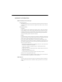
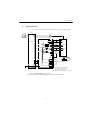
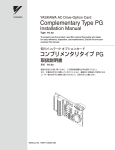
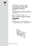
The external appearance and component names are shown in Fig. 1
Terminal TA3
(for connecting shielded sheath)
Terminal block TA1
Terminal block TA2
Connector to Inverter
control board (4CN)
Spacer mounting hole
(3.2 mm dia.)
Grounding lead wire
(connected to the grounding
terminal (G5: 12 (G),
G7 or F7: E (G)) of
Inverter control board)
Variable resistor for
adjusting +12 V power
Spacer mounting hole
(4.0 mm dia.)
Spacer mounting hole Variable resistor for
adjusting +5 V power
(3.2 mm dia.)
Fig. 1 Encoder (PG) Feedback Card (PG-X2)
8
3 Installation Procedure
3
Installation Procedure
3.1
Before Installation
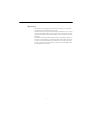
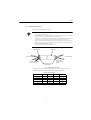
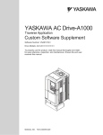
Remove contents from package and verify that a mounting spacer (code number
SRNT41028-9) is included with the PG-X2 card (see Fig. 2).
0.567 in. (14.4 mm)
Drive End
Option Card End
0.197 in. (5 mm)
1.32 in. (33.6 mm)
0.224 in. (5.7 mm)
Fig. 2 Spacer
3.2
Drive Installation Procedure
1. Turn OFF the main power and wait for the time specified on the cover of the Drive for
voltage to bleed off the DC bus capacitors. Remove the cover and verify that the
CHARGE indicator lamp is OFF.
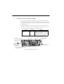
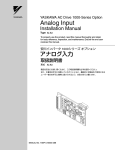
2. Insert the spacer (SRNT41028-9) into the spacer mounting hole in the mounting base of
the Drive (see Fig. 3). Drive models of 3.7 kW or smaller capacities have two closely
spaced mounting holes. Insert the spacer into the hole closest to the 7CN connector on
the control board. Insertion of the spacer into the incorrect hole will stack the spacer. Be
careful to insert in the proper hole in the proper inserting direction.
3. Align the two holes of the PG-X2 card and projections as shown in the detailed side
view, first at location (a) and then at (b), and precisely place the card on the option A
connector. Insert the spacer mounted at 2 above into the PG-X2 spacer mounting hole.
(See part A of the side view on the next page.)
4. Rotate the top edge of the card down into place, carefully aligning connector 4CN on
the back of the card with connector 4CN on the control board.
5. Gently press the card into place until 4CN and the spacer click into place.
6. Connect the grounding lead wire of the PG-X2 card to the grounding terminal (G5: 12
(G), G7 or F7: E (G)) on the control board.
9
Option A installation spacer
(SRNT41028-9, comes with PG-X2)
Spacer mounting hole
Option A
PG-X2
Top
4CN Option
A connector
Mounting base of Inverter
Option C
2CN Option
C connector
PG-X2
Control board
Mounting base of Inverter
Spacer mounting hole
Control board
Spacer
3CN Option
D connector
Option D
Mounting
base side
Option A side
Installation of spacer
(b)
Connector
terminal
(a)
Grounding terminal
(G5: 12 (G), G7 or F7: E (G))
Bottom
Details
Front View
Side view
Spacer mounting hole for option A
4CN
Option A connector
2CN
Option C connector
Option A installation spacer
(Comes with option A.)
Option C installaiton spacer
Option C
Option clip
(To secure option C or D)
Option D
3CN
Option D connector
Option D installation spacer
Option A
Option A installation spacer
Note: Be sure to remove the option clip before installing the PG-X2 card. If
the card is installed with the clip attached, the card cannot be correctly installed, and the card will perform poorly.
Fig. 3 Installation of the PG-X2 Card
10
4 Interconnection
4
Interconnection
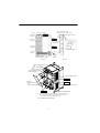
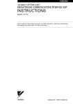
Fig. 4 shows interconnection between the Drive, the PG-X2 card, and peripheral equipment.
Inverter
MCCB
R
U
S
V
T
W
Motor
IM
PG
TA1 1 *
(+12 V)
2
IG
(0 V)
3
IP5
(+5 V)
+5 V
4 Output
F
1P12
Varispeed G7
PA
Pulse A
6
Pulse B
Pulse Z
12 V
0V
D
(Phase B)
A
P
7
PZ
G
C
P
5
PB
P
B
(Phase A)
8
GND
9
IG
10
TA3
(E)
TA2 1
4CN
4CN
2 Pulse A
3
(Forward rotation)
4 Pulse B Pulse monitor outputs
5
Pulse Z
6
7
E (G)
(E)
Grounding lead wire
Pulse A
Pulse B
PG speed controller card PG-X2
*Power supply for PG (From PG-X2)
TA1 1-2 (0 V): +12 V 200 mA max.
TA2 3-2 (0 V): +5 V 200 mA max.
DO NOT use the both supplies at the same time.
Note: The PG terminal symbols are the examples when using a Yaskawa’s motor.
PG type: LMA-BM- (line-driver output)
Fig. 4 Basic Interconnection Diagram (Example when Used with a G7-series Inverter)
11
5
Wiring
5.1
Terminal Functions
Table 1 Terminal Functions of PG-X2
Terminal Block
Symbol
Pin
No.
TA1
1
+12 V
2
0V
3
5V
4
+
5
−
TA2
Functions
6
+
7
−
Power supply for Encoder (PG)
(+12 V, +5 V must not be used at the same time.)
+12 V: 200 mA maximum
+5 V: 200 mA maximum
A Pulse
B Pulse
8
+
9
−
10
0V
Common
1
+
A Pulse
2
−
3
+
4
−
5
+
6
−
7
SG
Encoder (Pulse generator, PG) signal input.
RS-422 level input.
Z Pulse
Pulse monitor output.
RS-422 level input.
B Pulse
Z Pulse
Common
TA3
Shielded sheath connection terminal
PG Signal Output
The PG signal output (phases A and B) may vary according to installation location on the
motor. Refer to Fig. 4 for correct wiring.
In general, motor forward direction is counterclockwise (CCW) as viewed from the load
shaft. For YASKAWA’s motor, phase A of PG output leads phase B by a phase angle of 90°
in clockwise (CW) rotation. According to PG, phase A lags phase B by a phase angle of 90°
in clockwise (CW) rotation. In this case, when PG is installed at the opposite drive end, connect phases A and B output from PG to the option card as it is.
For YASKAWA’s Inverter motor with PG, PG is installed at the opposite drive end. Then,
phase A lags phase B by a phase angle of 90° at motor forward run. (Motor runs CCW as
viewed from PG.) Therefore, when using this motor or similar motors, connect phases A
and B to the option card after replacing phase output. The pulse monitor on this option
shows phase A leading phase B by a phase angle of 90°.
12
5 Wiring
5.2
Wiring Precautions
Make sure of the following when wiring.
NOTE
• Separate the control signal wires (terminal blocks TA1 and TA2) of the PG-X2 card from the main
circuit wires and other power cables.
• Use a shielded wire to connect the encoder (PG). Connect the wires as shown in Fig. 5 to prevent
noise interference. The wire distance must be 328 ft. (100 m) or less.
• To prevent noise, use shielded wire and separate from heavy current circuits (200 VAC or greater)
or relay drive circuits. (Wire length to the PG connector must be 328 ft. (100 m) or less.)
• If the PG signal is affected by noise, disconnect the grounding lead wire (E) from the grounding
terminal (G5: 12 (G), G7 or F7: E (G)) of the control board of the Inverter. Alternatively, change
the location of the shielded sheath connection.
• The recommended tightening torque is 0.22 to 0.25 Nxm.
Outer Jacket
Shielded Sheath
Encoder (PG) End
PG-X2 Connection
Do not connect
or ground sheild at
this end
Connect to terminal block
TA3 on PG-X2 card
Insulate these parts
with insulting tape
Fig. 5 Shielded Wire Termination
Applicable wire specifications for terminal blocks TA1 and TA2 are shown in Table 2.
Terminal: MKDS1 series manufactured by Phoenix Contact GmbH & Co.
Table 2 Wire Specifications
(mm2)
AWG
I (amps)
VAC
Thin Twisted Wire
1
16
12
125
Solid Wire
1.5
16
12
125
UL
−
22-16
10
300
CSA
−
28-16
10
300
CSA
−
28-16
10
150
13
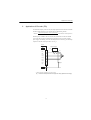
Strip back insulation for a distance of 0.22 inches (5.5 mm) on wire leads connected to the
PG-X2 card.
0.22 in. (5.5mm)
Fig. 6 Connecting Wire End for Terminal Blocks TA1 and TA2 Side
NOTE
Notes on selecting cables
• The thicker a cable is, the greater the pressure on the option card and the greater the possibility of
a failure occurring will be.
• The thinner a cable is, the poorer the electrical contact and the greater the possibility of the conductor breaking will be.
• The longer the cable is, the more likely a voltage drop in the PG power supply or PG signal will
occur.
14
6 Application of Encoder (PG)
6
Application of Encoder (PG)
The maximum frequency of the encoder (PG) output pulses that can be detected is 300 kHz.
To find the output frequency of your encoder (PG), use the following formula.
fPG (Hz) =
Motor rotation speed (min-1) at max. frequency output
60
× Encoder (PG) constant (pulses/rev)
Maximum power available to drive the encoder (PG) with the PG-X2 is 200 mA. Should
your encoder (PG) require more than 200 mA, it will be necessary to provide a separate
power supply. If momentary power loss ride-through function is necessary, provide backup
capacitor or take other necessary measures. See Fig. 7.
PG-X2
PG power supply
TA1
AC
IP12
1
IG
2
IP5
3
A (+)
A (−)
4
0V +12V
0V
*
+12 V
+
5
B (+)
6
B (−)
7
Z (+)
8
Z (−)
9
IG
10
+
−
PG
+
−
Signal
TA3
* Backup capacitor momentary power loss recovery
Fig. 7 Connection Example with Encoder (PG) when Using Separate Power Supply
15
7
PG-X2 Card Parameter List
If using the PG-B2 card with any Yaskawa drives other than the G5, F7, or G7, refer to the
instruction manual of the drive being used.
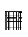
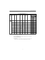
Table 3 PG-X2 Card Parameter List
PG-X2 Card Parameter List
Factory
Setting
Change
During
Operation *1
PG
Option
Setup
PG Pulses/
Rev
F1-01
PG constant
0 to 60000
600
×
PG Fdbk
Loss Sel
F1-02
Operation
selection at PG
open circuit
(PGO)
0 to 3
1
×
PG Overspeed Sel
F1-03
Operation
selection at
overspeed (OS)
0 to 3
1
PG Deviation Sel
F1-04
Operation
selection at
deviation
0 to 3
PG Rotation
Sel
F1-05
PG rotation
PG Output
Ratio
F1-06
PG Ramp PI/
I Sel
Data Selection
Control Method *2
G5, G7, F7
G7
Flux Vector*9
Setting
Range
Open loop Vector 2
Parameter
Name
Open loop Vector
Parameter
No.
V/f Control
Digital
Operator
Display
V/f w/PG Fdbk
Digital
Operator
Function
Group
×
{
×
{
×
×
{
×
{
×
×
×
{
×
{
{
3
×
×
{
×
{
{
0,1
0
×
0: Fwd=CCW
1: Fwd=CW
×
{
×
{
×
PG division rate
1 to 132
1
×
Effective with
PG-B
×
{
×
{
×
F1-07
Integral value
during accel/
decel enable/
disable
0,1
0
×
0: Disabled
1: Enable
×
{
×
×
×
PG Overspd
Level
F1-08
Overspeed
detection level
0 to 120 %
115 %
×
×
{
×
{
{
PG Overspd
Time
F1-09
Overspeed
detection delaytime
0 to 2.0 s
0.0 s *3
×
×
{
×
{
{
PG Deviate
Level
F1-10
Excessive speed 0 to 50 %
deviation detection level
10 %
×
×
{
×
{
{
PG Deviate
Time
F1-11
Excessive speed
deviation detection delay time
0 to 10 s
0.5 s
×
×
{
×
{
{
PG# Gear
Teeth 1
F1-12
Number of PG
gear teeth 1
0 to 1000
0
×
×
{
×
×
×
PG# Gear
Teeth 2
F1-13
Number of PG
gear teeth 2
0 to 1000
0
×
×
{
×
×
×
PGO Detect
Time *5
F1-14
PG open-circuit detection
time
0 to 10 s
2s
×
×
{
×
{
×
0: Ramp to Stop
1: Coast to Stop
2: Fast-Stop
3: Alarm Only
(1.0 s) *4
16
7 PG-X2 Card Parameter List
Table 3 PG-X2 Card Parameter List (cont’d)
Digital
Operator
Display
Parameter
No.
Parameter
Name
Setting
Range
Factory
Setting
Change
During
Operation *1
V/f Control
V/f w/PG Fdbk
Open loop Vector
Flux Vector*9
Open loop Vector 2
PG-X2 Card Parameter List
Digital
Operator
Function
Group
ASR
Tuning
ASR P Gain
1
C5-01
ASR proportional (P) gain 1
0 to
300.00
20.00 *3
{
×
{
×
{
{
ASR I Time
1
C5-02
ASR integral (I)
time 1
0 to
10.000 s
{
×
{
×
{
{
ASR P Gain
2
C5-03
ASR proportional (P) gain 2
0 to
300.00
{
×
{
×
{
{
ASR I Time
2
C5-04
ASR integral (I)
time 2
0 to
10.000 s
{
×
{
×
{
{
ASR Limit
C5-05
ASR limit
0.0 to 20
%
5.0 % *4
×
×
{
×
×
×
ASR Delay
Time 1 *8
C5-06
ASR primary
delay time 1
0.000 to
0.500 s
0.004 s *3
×
×
×
×
{
{
ASR Gain
SW Freq *8
C5-07
ASR switching
frequency
00 to
400.00 Hz
0.0 Hz
×
×
×
×
{
{
ASR Limit
C5-08
ASR integral (I) 0 to 400 %
limit
400 %
×
×
×
×
{
{
0.010 s
×
×
×
×
×
{
*6
*8
ASR Delay
Time 2 *7
* 1.
* 2.
* 3.
* 4.
* 5.
* 6.
* 7.
* 8.
C5-10
ASR primary
delay time 2
0.000 to
0.500 s
Data Selection
Control Method *2
G5, G7, F7
G7
(0.20) *4
0.500 s *3
(0.200 s) *4
20.00 *3
(0.02) *4
0.500 s *3
(0.050 s) *4
*3
{ = Enable, × = Disable
{ = Setting enable, × = Setting disable
For flux-vector control
For V/f with PG feedback control
For the F7, setting and reference are enabled for the software No. (U1-14) of 1030 or after.
ASR - Automatic Speed Regulator
For the G7 only
If using the flux-vector control with the F7, be sure to use an Inverter with a design revision
number of E or later. Versions C or earlier do not support the flux-vector control.
17
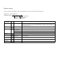
Revision History
The revision dates and numbers of the revised manuals are given on the bottom of the back cover.
MANUAL NO.ޓTOBP C730600 10A
Published in Japan
September 200504-12 1
Date of
publication
Date of
Publication
Rev.
No.
Revision number
Date of original
publication
Section
Revised Content
December 2004
−
−
New edition that was created by binding together the Japanese version (TO-C736-40.4) and the
English version (TOE-C736-40.4) of the VARISPEED-616G5 OPTION CARD PG SPEED CONTROLLER CARD PG-X2 INSTRUCTIONS and by adding information on the Varispeed F7 and
the Varispeed G7 Inverters.
September 2005
1
Back cover
Revision: Address
October 2006
2
WARRANTY
INFORMATION
Addition: Warranty Information
2
Revision: Fig. 1 Encoder (PG) Feedback Card (PG-X2)
5.2
Revision: NOTE on Wiring Precautions
May 2007
3
Back cover
Revision: Revision number
September 2007
4
Back cover
Revision: Address
January 2008
5
Back cover
Revision: Address
September 2008
6
Back cover
Revision: Address
June 2010
7
Back cover
Revision: Address
Varispeed G5/F7/G7 OPTION CARD
PG SPEED CONTROL CARD PG-X2
INSTRUCTIONS
IRUMA BUSINESS CENTER (SOLUTION CENTER)
480, Kamifujisawa, Iruma, Saitama, 358-8555, Japan
Phone: 81-4-2962-5696 Fax: 81-4-2962-6138
YASKAWA ELECTRIC CORPORATION
New Pier Takeshiba South Tower, 1-16-1, Kaigan, Minatoku, Tokyo, 105-6891, Japan
Phone: 81-3-5402-4511 Fax: 81-3-5402-4580
http://www.yaskawa.co.jp
YASKAWA ELECTRIC AMERICA, INC.
2121 Norman Drive South, Waukegan, IL 60085, U.S.A.
Phone: (800) YASKAWA (800-927-5292) or 1-847-887-7000 Fax: 1-847-887-7310
http://www.yaskawa.com
YASKAWA ELÉTRICO DO BRASIL COMÉRCIO LTDA.
Avenda Fagundes Filho, 620 Bairro Saude, São Paulo, SP04304-000, Brasil
Phone: 55-11-3585-1100 Fax: 55-11-5581-8795
http://www.yaskawa.com.br
YASKAWA ELECTRIC EUROPE GmbH
Hauptstraβe 185, 65760 Eschborn, Germany
Phone: 49-6196-569-300 Fax: 49-6196-569-398
YASKAWA ELECTRIC UK LTD.
1 Hunt Hill Orchardton Woods, Cumbernauld, G68 9LF, United Kingdom
Phone: 44-1236-735000 Fax: 44-1236-458182
YASKAWA ELECTRIC KOREA CORPORATION
7F, Doore Bldg. 24, Yeoido-dong, Youngdungpo-Ku, Seoul, 150-877, Korea
Phone: 82-2-784-7844 Fax: 82-2-784-8495
YASKAWA ELECTRIC (SINGAPORE) PTE. LTD.
151 Lorong Chuan, #04-02A, New Tech Park, 556741, Singapore
Phone: 65-6282-3003 Fax: 65-6289-3003
YASKAWA ELECTRIC (SHANGHAI) CO., LTD.
No. 18 Xizang Zhong Road, Room 1702-1707, Harbour Ring Plaza, Shanghai, 200001, China
Phone: 86-21-5385-2200 Fax: 86-21-5385-3299
YASKAWA ELECTRIC (SHANGHAI) CO., LTD. BEIJING OFFICE
Room 1011A, Tower W3 Oriental Plaza, No. 1 East Chang An Ave.,
Dong Cheng District, Beijing, 100738, China
Phone: 86-10-8518-4086 Fax: 86-10-8518-4082
YASKAWA ELECTRIC TAIWAN CORPORATION
9F, 16, Nanking E. Rd., Sec. 3, Taipei, Taiwan
Phone: 886-2-2502-5003 Fax: 886-2-2505-1280
YASKAWA ELECTRIC CORPORATION
YASKAWA
In the event that the end user of this product is to be the military and said product is to be
employed in any weapons systems or the manufacture thereof, the export will fall under
the relevant regulations as stipulated in the Foreign Exchange and Foreign Trade
Regulations. Therefore, be sure to follow all procedures and submit all relevant
documentation according to any and all rules, regulations and laws that may apply.
Specifications are subject to change without notice
for ongoing product modifications and improvements.
© 2004-2010 YASKAWA ELECTRIC CORPORATION. All rights reserved.
MANUAL NO. TOBP C730600 10B
Published in Japan June 2010 04-12 7 -0
10-3-3