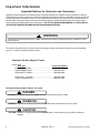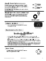
1
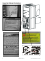
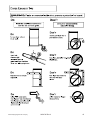
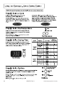
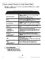
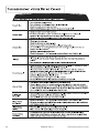
This manual is to be used by qualified appliance
technicians only. Maytag does not assume any
responsibility for property damage or personal
injury for improper service procedures done by
an unqualified person.
Neptune DC
This Base Manual covers general information
Refer to individual Technical Sheet
for information on specific models
This manual includes, but is
not limited to the following:
MCE8000AY
MCG8000AW
16022785
Revision 0
November 2003
Important Information
Important Notices for Servicers and Consumers
Maytag will not be responsible for personal injury or property damage from improper service procedures. Pride and
workmanship go into every product to provide our customers with quality products. It is possible, however, that during
its lifetime a product may require service. Products should be serviced only by a qualified service technician who is
familiar with the safety procedures required in the repair and who is equipped with the proper tools, parts, testing
instruments and the appropriate service information. IT IS THE TECHNICIANS RESPONSIBLITY TO REVIEW ALL
APPROPRIATE SERVICE INFORMATION BEFORE BEGINNING REPAIRS.
!
WARNING
To avoid risk of severe personal injury or death, disconnect power before working/servicing on appliance to avoid
electrical shock.
To locate an authorized servicer, please consult your telephone book or the dealer from whom you purchased this
product. For further assistance, please contact:
Customer Service Support Center
CAIR Center
Web Site
Telephone Number
WWW.AMANA.COM .................................................1-800-843-0304
WWW.JENNAIR.COM ...............................................1-800-536-6247
WWW.MAYTAG.COM ...............................................1-800-688-9900
CAIR Center in Canada ............................................1-800-688-2002
Amana Canada Product ............................................1-866-587-2002
Recognize Safety Symbols, Words, and Labels
! DANGER
DANGER—Immediate hazards which WILL result in severe personal injury or death.
!
WARNING
WARNING—Hazards or unsafe practices which COULD result in severe personal injury or death.
!
CAUTION
CAUTION—Hazards or unsafe practices which COULD result in minor personal injury, product or property
damage.
2
16022785 Rev. 0
©2003 Maytag Appliances Company
Table of Contents
Important Information ...................................................... 2
Important Safety Information ........................................... 4
General Information
Model Identification ..................................................... 8
Serial Label Location ................................................... 8
Model Nomenclature ................................................... 9
Model Specifications ................................................. 10
Troubleshooting Procedures
Trouble Shooting General Symptoms ....................... 11
Read Sensor Inputs ................................................... 12
Membrane Keypad Utility .......................................... 13
Upper/Lower Dryer Sub-System Check .................... 13
Accessing Diagnostic Codes .................................... 13
Diagnostic Codes ...................................................... 14
Reset to Factory Default Conditions ......................... 14
Sensor Bar Diagnostics ............................................ 15
Consumer Codes ...................................................... 15
View Cycle Statistics ................................................ 15
Membrane Pad Continuity Checks............................ 16
©2003 Maytag Appliances Company
Logic Board Connectors ............................................ 17
Relay Header Connections ........................................ 18
Power And Relay Board Connectors ......................... 18
Disassembly Procedures
Lower Door Reversal/Removal ................................... 19
Door Hook Removal ................................................... 19
Shaker Removal ........................................................ 19
Console Removal ...................................................... 20
Logic Board Removal ................................................ 21
Front Access Panel Removal .................................... 21
Tumbler Drum Removal ............................................. 23
Heater Assembly Removal ........................................ 23
Relay Board Removal ................................................ 24
Blower And Motor Removal ....................................... 24
Water Valve Removal ................................................ 25
Steamer Blower Removal .......................................... 25
Steamer Heater Removal ........................................... 26
Appendix A
Installation Instructions ............................................. 28
Appendix B
Use And Care ............................................................ 41
16022785 Rev. 0
3
Important Safety Information
! WARNING
To avoid risk of fire, electric shock, serious injury, or death when using your dryer, follow these basic precautions:
1. Read all instructions before
using dryer.
2. Install dryer according to
Installation Instructions. Refer to
the Grounding Instructions in the
Installation Instructions for
proper grounding of the dryer.
3. Do not dry articles that have
been cleaned in, washed in,
soaked in, or spotted with
gasoline, dry-cleaning solvents,
or other flammable or explosive
substances. Vapors could ignite
or explode.
4. Do not use dryer to dry clothes
which have traces of any
flammable substance, such as
vegetable oil, cooking oil,
machine oil, flammable
chemicals, thinner, etc., or
anything containing wax or
chemicals, such as mops and
cleaning cloths. Flammable
substances may cause fabric to
catch fire by itself.
5. Do not store or use gasoline or
other flammable vapors and
liquids near this or any other
appliance.
6. Do not allow children to play on
or in dryer. Close supervision of
children is necessary when
dryer is used near children, a
safety rule for all appliances.
7. Before dryer is removed from
service or discarded, remove
doors to drying compartment.
8. Do not reach into dryer if
cylinder is revolving.
9. Do not install or store dryer
where it will be exposed to water
and/or weather.
10. Do not tamper with dryer
controls.
11. Do not repair or replace any part
of dryer or attempt any service,
unless specifically recommended
in user-maintenance instructions
or in published user-repair
instructions that you understand
and have skills to carry out, if you
are a consumer.
12. To reduce risk of electric shock or
fire, do not use extension cords or
adapters to connect dryer to
electrical power source.
13. Use the dryer only for its intended
purpose, drying clothes.
14. Always disconnect dryer from
electrical supply before
attempting any service.
Disconnect power cord by
grasping the plug, not the cord.
15. Do not use heat to dry articles
containing foam rubber or
similarly textured rubberlike
materials.
16. Always clean the lint filter after
every load. A layer of lint in the
filter reduces drying efficiency and
prolongs drying time.
17. Use only fabric softeners or
products to eliminate static that
are appropriate for automatic
dryers.
18. Keep your dryer in good condition.
Bumping or dropping dryer can
damage safety features. If
damage occurs, have dryer
checked by qualified service
technician.
19. Replace worn power cords and/or
loose plugs.
20. Do not tumble fiberglass curtains
and draperies unless the label
says it can be done. If they are
dried, wipe out the cylinder with a
damp cloth to remove particles of
fiberglass.
21. Always read and follow
manufacturer’s instructions on
packages of laundry aids. Heed
all warnings or precautions. To
reduce risk of poisoning or
chemical burns, keep products
away from children at all times,
preferably, in a locked cabinet.
22. Never operate dryer with guards
and/or panels removed.
23. Do not operate dryer with
missing or broken parts.
24. Do not bypass safety devices.
25. Keep area around the exhaust
opening and adjacent
surrounding areas free from
accumulation of lint, dust, and
dirt.
26. Interior of dryer and exhaust duct
should be cleaned periodically
by qualified service personnel.
27. Dryer will not operate with
loading door open. DO NOT
bypass door safety switch by
permitting dryer to operate with
door open. Dryer will stop
tumbling when door is opened.
Do not use dryer if it does not
stop tumbling when door is
opened or starts tumbling
without pressing or turning the
START mechanism. Remove the
dryer from use and call
the service person.
28. Remove laundry immediately
after the dryer stops.
29. ALWAYS follow the fabric care
instructions supplied by the
garment manufacturer.
Save These Instructions
4
16022785 Rev. 0
©2003 Maytag Appliances Company
Important Safety Information
!
! WARNING
WARNING
The California Safe Drinking Water and Toxic
Enforcement Act of 1986 (Proposition 65) requires the
Governor of California to publish a list of substances
known to the State of California to cause cancer or
reproductive harm and requires business to
warn consumers of potential exposures to such
substances.
Users of this appliance are hereby warned that the
burning of gas can result in low-level exposure to some
of the listed substances, including benzene,
formaldehyde and soot, due primarily to the incomplete
combustion of natural gas or liquid petroleum (LP) fuels.
Exhaust ducts should be kept free of obstructions and
properly exhausted dryers will minimize exposure.
To avoid risk of personal injury or death due to
electrical shock:
•
•
•
•
•
•
•
•
Electrical Service Information
•
•
•
Electrical Dryers
• 240 VAC, 60 Hz, 30 Amps,
3–wire or 4–wire installations
Gas Dryers
• 120 VAC, 60 Hz, 20 Amps, 3–wire installations
Observe all local codes and ordinances.
Disconnect electrical power to unit before servicing.
Ground appliance properly.
Check with a qualified electrician if you are not sure
this appliance is properly grounded.
DO NOT ground to gas line.
DO NOT ground to cold water pipe if pipe is
interrupted by plastic, non-metallic gaskets, or other
insulating (non-conducting) materials.
DO NOT modify plug on power cord. If plug does not
fit electrical outlet, have proper outlet installed
by qualified electrician.
DO NOT have a fuse in the neutral or ground circuit.
A fuse in the neutral or ground circuit could result in
an electrical shock.
DO NOT use an extension cord with this appliance.
DO NOT use an adapter plug with this appliance.
DO NOT pinch power cord.
Gas Connection Information
! WARNING
About Ground Wires
In the event of an electrical short circuit, a ground wire
reduces the risk of electric shock by providing an escape
wire for the electric current.
Standard accepted color coding for ground wires is green
or green with a yellow stripe.
Grounding wires and wires colored like grounding wires
are NOT to be used as current carrying conductors.
! WARNING
To reduce the risk of fire, electric shock, serious injury
or death, all wiring and grounding must conform with
the latest edition of the National Electric Code, ANSI/
NFPA 70, or the Canadian Electrical Code, CSA C22.1,
and such local regulations as might apply. It is the
customer’s responsibility to have the wiring and fuses
checked by a qualified electrician to make sure your
home has adequate electrical power to operate the
dryer.
To avoid death, personal injury or property damage,
from fire or explosion, information in this manual must
be followed exactly.
Do not store or use gasoline or other flammable vapors
and liquids in the vicinity of this or any other appliance.
WHAT TO DO IF YOU SMELL GAS
• Do not try to light any appliance.
• Do not touch any electrical switch; do not use any
phone in your building.
• Immediately call your gas supplier from a neighbor’s
phone. Follow the gas supplier’s instructions.
• If you cannot reach your gas supplier, call the fire
department.
Installation and service must be performed by a
qualified installer, service agency or the gas supplier.
! WARNING
To reduce the risk of fire and exposure to combustion
gases, the dryer MUST be exhausted to the outdoors.
DO NOT exhaust dryer air into a window well, gas vent,
chimney or enclosed, unventilated area, such as an
attic, wall, ceiling, crawl space under a building or
concealed space of a building.
©2003 Maytag Appliances Company
16022785 Rev. 0
5
Important Safety Information
6
16022785 Rev. 0
©2003 Maytag Appliances Company
Important Safety Information
For proper operation at altitudes above
2,500 feet
The natural gas valve spud orifice size must be reduced to
ensure complete combustion. See table.
Altitude
Ft (M)
3000 (915)
6000 (1830)
8000 (2440)
9000 (2740)
10000(3050)
Orifice
Size #
43
44
45
46
47
Part
number
503778
58719
503779
503780
503781
Gas Connection
Connect gas supply to dryer using a new stainless steel
flexible connector or hard pipe (check local codes)
according to illustration. Test for leaks and check burner
flame after gas supply is connected.
• Dryer must be connected to type of gas as shown on
nameplate located in the door recess.
• Use pipe joint compound insoluble on LP (propane)
Gas, or Teflon tape, on all pipe threads.
• Purge air and sediment from gas supply line before
connecting it to the dryer. Before tightening the
connection, purge remaining air from gas line to dryer
until odor of gas is detected. This step is required to
prevent gas valve contamination.
Use a new stainless steel flexible connector only if
allowed by local codes (use A.G.A. certified connector).
3/8" NPT gas
connection
1/8" NPT pipe plug
(for checking inlet
gas pressure)
Install Equipment
shut-off valve
within 6' (1.8 m) of dryer.
Black iron piping:
• Shorter than 20’ (6.1 m) – use 3/8” piping
• Longer than 20’ (6.1) m) – use 1/2” piping
Testing for Gas Leaks
After final gas connection is made, turn on manual gas
valve and test all connections in gas supply piping for gas
leaks. Leak testing of the appliance shall be conducted
according to the manufacturer’s instructions.
1. Place soap suds on connections.
2. If bubbles appear, a leak is present. Shut off gas
supply valve.
3. Tighten joint if leak is at factory fitting.
• If leak is not at factory fitting, unscrew, apply more
joint compound, and tighten to correct leak.
©2003 Maytag Appliances Company
16022785 Rev. 0
7
4. Retest connection for leak after tightening or adding
joint compound.
• Retest any connections that were disturbed.
L.P./Propane
DO NOT connect dryer to L.P./Propane gas service
without converting the gas valve. A Sales Accessory L.P./
Propane Gas Conversion Kit 63-6766 must be installed.
General Information
Model Identification
Complete registration card and promptly return. If
registration card is missing:
• For Maytag product call 1-800-688-9900 or visit the
Web Site at www.maytag.com
• For product in Canada call 1-866-587-2002 or visit the
Web Sites at www.maytag.com or www.jennair.com
When contacting provide product information located on
rating plate. Record the following:
Model Number:
____________________
Manufacturing Number:
____________________
Serial or S/N Number:
____________________
Date of purchase:
____________________
Dealer’s name and address:
____________________
Service
Keep a copy of sales receipt for future reference or in
case warranty service is required. To locate an authorized
servicer:
• For Maytag/Jenn-Air product call 1-800-462-9824 or
visit the Web Site at www.maytag.com or
www.jennair.com
• For product in Canada call 1-866-587-2002 or visit the
Web Sites at www.maytag.com or www.jennair.com
Warranty service must be performed by an authorized
servicer. We also recommend contacting an authorized
servicer, if service is required after warranty expires.
Parts and Accessories
Purchase replacement parts and accessories over the
phone. To order accessories for your product call:
• For Maytag/Jenn-Air product call 1-800-462-9824 or
visit the Web Site at www.maytag.com or
www.jennair.com
• For product in Canada call 1-866-587-2002 or visit the
Web Sites at www.maytag.com or www.jennair.com
Extended Service Plan
We offer long-term service protection for this new oven.
• Dependability PlusSM Extended Service Plan is
specially designed to supplement Maytag’s strong
warranty. This plan covers parts, labor, and travel
charges.
Call 1-800-925-2020 for information.
Serial Label is located in the upper left hand corner of the
lower door opening.
8
16022785 Rev. 0
©2003 Maytag Appliances Company
General Information
Drying Center Nomenclature
Drying Center Nomenclature
M
C
E
8
0
0
0
A
Y
W
Color
W
Q
Brand
A
C
G
H
J
M
N
U
Y
Amana
Magic Chief
Graffer &
Sattler
Hardwick
Jenn-Air
Maytag
Norge
Universal
Crosley
White
Bisque
Listing
W
Y
Z
Y
Product Type
C
Drying Center
120V-60hz
240V-60hz
Canada 240V-60hz
220-240 V / 50-60 Hz
Marketing Code
Fuel
G
E
This identifies which
version of production the
unit is.
Gas
Electric
Feature Content
8000
©2003 Maytag Appliances Company
16022785 Rev. 0
Feature Package
9
General Information
UPPER DRYING CABINET
Capacity (cu. ft.)
Controls
Drying System
C.F. M.
17.3
LED
BreezeCare™
80
MODEL MCE/G8000
R
T
R
W
Low
Extra Low
Flat Dry Shelves
140º F
110º F
5
W
LOWER TUMBLE DRYER
Controls
Drying System
C.F.M.
Cycles
Wrinkle Release
LED
GentleBreeze™
170
4
•
DRYING CENTER SPECIFICATIONS
W
T
Uncrated Dimensions: 33 1 /2"w x 29"d x 74"h
Regular
Medium
Low
Extra Low
150º F
145º F
140º F
125º F
Crated Dimensions: 36.8"w x 31.3"d x 76.3"h
Uncrated Weight: 245 lbs.
Crated Weight: 260 lbs.
V
R
10
16022785 Rev. 0
©2003 Maytag Appliances Company
Troubleshooting Procedures
!
WARNING
To avoid risk of electrical shock, personal injury or death, disconnect power to unit before servicing, unless testing
requires power.
Troubleshooting Guide
Maytag Neptune™ Drying Center
• Due to possibility of personal injury or property damage, always contact an authorized technician for servicing or
repair of this unit.
• Faulty Heater Relays.
Will Not Run
• Drive motor centrifugal start switch not allowing
Will not start or run:
voltage to gas valve or heating element.
• All wires are hooked up to their corresponding
terminals.
Will Not Dry (Gas Models)
• Dryer is plugged in.
Poor Gas Ignition
• Blown fuse or circuit breaker.
• Door switch functional...door closed.
When the dryer is operated on a heat setting, the igniter
• Poor connection between membrane switch and logic should be energized and burner shall fire within 45
seconds at 120 VAC. The failure of a component in this
board, or faulty membrane switch. Use "Pd" utility to
system will usually be indicated by one of three
check function of membrane switch.
• Faulty motor relay, use diagnostic utilities to manually symptoms:
operate relay.
The igniter does not glow. If the igniter does not heat
• Drive motor functional.
• Blown thermal fuse.
up, remove power and using an ohmmeter, check the
Motor runs/ tumbler will not turn:
following:
• Open flame sensor
• Belt off or broken/damaged.
• Open igniter
• Idler tension spring too weak or stretched.
• Shorted booster coil
• Idler pulley jammed or stuck.
• Open wiring
Runs a few minutes and then stops:
Igniter
glows - No gas ignition. If the igniter heats up
• Lint buildup around drive motor.
but the main burner flame is not ignited, remove power
• Low voltage present.
and using an ohmmeter, check the following:
• Blower impeller blocked in blower
• Open secondary coil
housing.
• Open holding coil
• Drive motor - start switch contacts stuck closed.
• Open wire harness
Blows fuses or trips circuit breaker:
The gas is ignited but the flame goes out. If a normal
Electric Models
• The amperage readings are at 240 volts. One line with ignition takes place and after a short while the flame goes
24 amps, and the other line with 21 amps. The neutral out, check for the following:
• Radiant sensor contacts opening
line will be at 3 amps. If the above amperages are
prematurely.
present, then the house wiring, fuse box or circuit
• Weak gas valve coil may open when
breaker should be suspected.
stressed by higher temperatures.
• Shorted heating element to housing.
Improper drying/clothes wrinkled/ rough texture/long
• Incorrect wiring or a wire shorting to ground.
dry time:
• Drive motor winding shorting to ground.
• Lint filter is not clean.
Gas Models
• Restriction in exhaust.
• During ignition the dryer will draw 7 amps. With the
• Outside exhaust hood damper door stuck closed.
burner ON, the dryer will draw 3 amps. If the dryer is
drawing amperages above this, then the house wiring, • Exhaust too long, too many elbows, flex ductwork
installed.
fuse box or circuit breaker is suspected to be at fault.
• Poor makeup air available for the dryer.
• Igniter harness loose and shorted to base.
• Incorrect wiring or wire shorted to ground.
• Incorrect tumbler speed. Tumbler belt slipping.
• Open centrifugal switch in motor
• Blower impeller bound; check for foreign material in
• Drive motor winding shorting to ground.
blower area.
Will Not Dry
• Customer overloading dryer.
Will not heat (motor runs):
• Check clothing labels for fabric content and cycle
selected.
• Open heating element.
• Gas valve coil opens - weak point in coil opens when
• Hi-Limit trips easily or is open.
stressed under heated conditions.
• Faulty Thermistor.
©2003 Maytag Appliances Company
16022785 Rev. 0
11
Troubleshooting Procedures
!
WARNING
To avoid risk of electrical shock, personal injury or death, disconnect power to unit before servicing, unless testing
requires power.
• Clothes too wet due to insufficient spin out by washer. Note: Pressing the Off button exits the Diagnostic State
• Faulty Sensor Bar. See Sensor Bar diagnostic section. and places the control board in the Sleep State.
Troubleshooting the Sensor-Dry circuit:
• Check for incorrect wiring of the electrical connector at
the electronic control board.
Dryer runs for 2 minutes, jumps to a 1-minute cool
down and then stops. Open Sensor Dry circuit. Check
Sensor Bar. Refer to Sensor Bar Diagnostics section.
• Dryer does not shut off. Check sensor for continuity. If
found, replace sensor bar or clean with alcohol. Some
fabric softener sheets will coat the sensor bars.
Noisy and/Or Vibration
• Thumping. Check for loose tumbler baffle, rear
tumbler roller(s) worn or misaligned, out-of-round
tumbler or high weld seam on tumbler.
• Ticking. Check for loose wire harness or object
caught in blower wheel area.
• Scraping. Check for front or rear bulkhead felt seal
out of position or worn tumbler front bearings.
• Roaring - Check for blower wheel rubbing on blower
housing or bad motor bearings.
• Popping or squealing sound. Check for a sticky or
frayed belt.
System Check Mode
The Diagnostic State provides a set of utilities not
intended for use by the consumer. Diagnostic State
utilities provide specialized functions for performance
evaluation and service. Upon recovery from a power
failure, the Drying Cabinet always returns to the Normalprogram State. Any Diagnostic State utility active prior to
the power failure is effectively cancelled.
To enter the Diagnostic State from the Normal Program
State on the upper or lower dryer half of the keypad,
press the Signal (+) button and Time Adjust ^
simultaneously for five (5) seconds. Upon entry to the
Diagnostic State, the corresponding 7-segment display
shows “dd”. Attempts to enter the Diagnostic State while
a dryer cycle is active causes the invalid selection chime
to sound.
After 10 minutes of inactivity the diagnostic state will be
canceled, and the machine will return to normal
operation. To exit the Diagnostic State, press the Signal
(-) button.
Either half of the keypad may be used to request the
Diagnostic State. Once initiated, all key entries must be
made from the same half of the keypad. The LED
indicators and 7-segment displays on the remaining half
of the keypad are extinguished. Any key presses to the
unused portion of the keypad are ignored and sound the
invalid selection chime.
12
Diagnostic State Menu
Enter a menu item by using the Time Adjust ^or v
arrows to see the letter code desired and press Signal
(+).
NOTE: * indicates a submenu with further explanation
given below.
Menu
dd
Description
Beginning of Diagnostic State Menu
cc
Factory Use Only
cd
Clear Diagnostic Codes
ch
Clear Help Codes
******cS
View Cycle Counts
****dL
View Diagnostic Code List
FS
Factory Use Only
hL
View Help Code List
Lo
Logic Board Output Self-test (Display
will show “PASS” “PASS” or “FAIL”
“FAIL”
pc
Factory Use Only
*Pd
Membrane Key Pad Utility
**rd
Read Sensor Inputs
***Sc
Sub-system Check
SF
Software Version
rS
Reset to Factory Default Conditions
rd**Read Sensor Inputs
This utility allows the user to enable or disable the display
of sensor input values. Once enabled, the user exits the
Diagnostic State and the 7-segment display used to
make the selection alternates between the sensor value
and the time remaining. All other features operate as
normal. It is not necessary to start a cycle for the sensor
value to begin displaying. The user may display lower
dryer values on the upper dryer half of the keypad with
the converse also allowed.
After exiting the Diagnostic State with the sensor display
function enabled, the 7-segment display continuously
cycles through a 4-step sequence. Each step lasts 1.5
seconds. The sequence consists of the following:
“n=” appears to indicate that the next value is the time
remaining. The time remaining value appears on the
display.
“xx=” appears to indicate that the next value is from the
selected sensor. Where “xx.xx” is the item selected from
the sensor display menu. The sensor value appears on
16022785 Rev. 0
©2003 Maytag Appliances Company
Troubleshooting Procedures
!
WARNING
To avoid risk of electrical shock, personal injury or death, disconnect power to unit before servicing, unless testing
requires power.
Example:
1) To read measured temperature, scroll to “rd” on the
menu and press Signal (+).
2) Upon entry to the utility, “OFF” appears on the
display.
3) Using the Time Adjust v arrow button scroll to “Ld”
menu item from the Table.
Note: To exit the utility before running a test, press
Signal (-). The display will show “rd”. To exit diagnostics
press, Signal (-) again. The display will show “dd”.
4) Press Signal (-) twice to initiate the menu item.
5) Time and Temperature are displayed.
6) Press “OFF” to exit the test.
Sensor Display Menu
Menu
Description
OFF
Ld
Sensor display disabled
Lower Dryer Outlet
Temperature
Upper Dryer Outlet
Temperature
Upper Dryer Door
Switch
Lower Dryer Heater
Energized
Lower Dryer Door
Switch
Lower Dryer Sensor Bar
Spare Thermistor Input
Displayed Value
NA
Degrees Fahrenheit
Sub System Check Menu
Menu
Description
Su
Beginning of Menu
bo
Operate Upper Dryer Blower Motor
Fd
Operate Lower Dryer Motor
hr
Operate Upper Dryer Heater and Blower (Temp
displayed opposite side)
hh
Operate Lower Heater and Blower at High Wattage
(Temp displayed opposite side)
hL
Operate Lower Heater and Blower at Low Wattage
(Temp displayed opposite side)
So
Operate Upper Dryer Shaker Motor
ho
Operate Upper Dryer Blower, Heater and Water Valve
d1
Unused
d2
Operate Wax Motor for Upper Dryer Damper
Diagnostic Codes:
The diagnostic/help code information displayed provides
information about the machine. Any abnormalities
uS
On or OFF (On = door open)
monitored by the board will be identified as either a Help
or Diagnostic code. Diagnostic Codes will be logged and
LE
On or OFF (On = energized)
stored in permanent memory (maximum nine in the list).
LS
On or OFF (On = door closed)
A Diagnostic Code is logged when there is a problem
with the system. It may be recommended the machine be
*****db
On or OFF (On = hit detected)
serviced.
SP
Degrees Fahrenheit
Software checks for open or shorted thermistors and
door switch failures only during active cycles. Software
continuously checks for stuck button conditions.
*Membrane Keypad Utility
“Stuck Button” fault detection uses the lower dryer cycle
To select the Membrane Keypad utility, scroll to “Pd” on
count when logging a diagnostic code. Fault detection
the menu and press Signal (+).
Upon entry to the utility, all LED indicators and 7-segment logs a code once after initially detecting a fault. A fault
must clear before logging additional occurrences.
display LED elements illuminate. Pressing each key
extinguishes one or more of the keypad indicators or 7****Accessing Diagnostic Codes
segment display LED elements. All the keys must
To view the Diagnostic Codes List, scroll to “dL” on the
function properly to extinguish all the LED elements. The
menu and press Signal (+). Upon entry to the utility,
LED extinguished may not be adjacent to the keypad
“SOL” appears on the display indicating start of list.
pressed. Do not press Signal (-) or you will exit the utility.
Use the Time Adjust ^ (up arrow) and Time Adjust v
(down arrow) buttons to step through the list. The display
To exit the utility and return to the menu, press
shows “End” after the last entry in the list is reached.
Signal (-). Upon return to the Main Menu, “Pd”. To
Attempts to step past the beginning or end of the list
check Membrane Pad with ohm meter see chart.
cause the invalid selection chime to sound.
***Upper and Lower Dryer Sub-system Check
To select the Clear Diagnostic Codes utility, scroll to
Utilities
“cd” on the menu and press Signal (+).
To view the Sub-system Check Utility menu, scroll to “Sc”
Upon entry to the utility, “cL” appears on the display.
on the main menu and press Signal (+).
Press Signal (+) again to clear all Diagnostic Codes for
To exit the Sub-system Check Utility Menu and return to both the upper and lower dryer. The message “AC”
appears on the display to indicate All Clear after the clear
the Main Menu, press Signal (-) at any of the menu
function completes.
items. Upon return to the Main Menu, “Sc” appears on
To exit the utility and return to the menu, press
the display.
Signal (-). Upon return to the Main Menu, “cd” appears
Upon entry to the Sub-system Check Utility Menu, “SU”
on the display.
appears on the display.
Ud
Degrees Fahrenheit
Pd
dL
Sc
©2003 Maytag Appliances Company
cd
16022785 Rev. 0
13
Troubleshooting Procedures
!
WARNING
To avoid risk of electrical shock, personal injury or death, disconnect power to unit before servicing, unless testing
requires power.
Diagnostic Codes
rS Reset to Factory Default Conditions
Code
Description
SOL
1
Start of list
Lower Dryer
Thermistor
Short Sensed
2
Lower Dryer
Thermistor
Open Sensed
3
Lower Dryer
Door Circuit
Failure
4
Not Used
Not Used
5
6
Non Volatile
Memory
8
Stuck Button
9
Not Used
10
Not Used
11
Upper Dryer
Thermistor
Short Sensed
12
13
Upper Dryer
Thermistor
Open Sensed
Upper Dryer
Door Circuit
Failure
Trigger
Action Taken
If temperature > 200
Check for:
degrees for 2 minutes. - Clogged lint
screen.
- Restricted vent
system.
Failed thermistor
If the temperature is
Check for:
low with an increase of - Low ambient
temperature expected,
temperature in
and no increase
room (Below
occurring after 3
50°F/10°C).
minutes.
- Outside vent
damper is stuck
open in
wintertime.
Loose or open wire
terminals
Low for more than 1
Check for:
second.
- Loose or open
wire terminals in
Door Sense circuit.
Problem Detected with
integrity of parameters
stored in EEPROM
memory.
A button sensed as
pressed more than 75
seconds, is assumed
as stuck.
Step 1 From the Normal Program State, press the
Signal (+) button and Time Adjust • to enter
the Diagnostic State from the upper or lower
dryer keypad.
Step 2 Scroll to the “rS” display on the menu and press
Signal (+). The number “004” appears on the
display to indicate the number of remaining
steps needed to complete the reset sequence.
Step 3 Open and leave open the Lower Dryer Door.
The remaining step count decrements to “003”
on the display.
Step 4 Press the Time Adjust • and Time Adjust ‚
at the same time. The remaining step count
decrements to “002” on the display.
Step 5 Press the Temperature • and Time Adjust ‚
at the same time. The remaining step count
decrements to “001” on the display.
Step 6 Close the Lower Dryer Door. The remaining
step count decrements to “000” once the
Factory Default settings have been restored.
The "Power On Reset" sequence then
executes.
The remaining step count resets to four and the invalid
selection chime sounds when any of the following
conditions occur:
Disregard
Check for:
- Run membrane
pad check and
replace console
w/membrane pad if
necessary..
If temperature > 200
Check for:
degrees for 2 minutes. - Failed hi-limit
thermostat on
steamer.
- Failed thermal
fuse on heater.
Failed thermistor
If the temperature is
Check for:
low with an increase of - Low ambient
temperature expected,
temperature in
and no increase
room (Below
occurring after 3
50oF/10oC).
minutes.
- Check door vent
seals.
Loose or open wire
terminals on
steamer circuit.
Low for more than 1
Check for:
second.
- Loose or open
wire terminals
•
A reset step is performed out of sequence.
• An unexpected key combination is entered.
The time window expires.
Opening the door to complete the first step marks the
beginning of the time window.
This function does not clear either of the upper or lower
dryer cycle counters. All other parameters stored in nonvolatile memory are returned to the Factory Default
values.
The Reset Utility functions the same regardless of which
half of the keypad it is initiated from. Once the utility is
initiated, all key combinations must be made from the
same half of the keypad used to initiate the utility.
The Signal (-) key exits the Reset Utility and returns to
the “rS” display on the main menu. Pressing the Signal
(-) key any time prior to completion of the reset
sequence cancels the sequence and then returns to the
main menu.
To restore Factory Default settings for the dryer
controls, complete the following sequence within one (1)
minute.
14
16022785 Rev. 0
©2003 Maytag Appliances Company
Troubleshooting Procedures
!
WARNING
To avoid risk of electrical shock, personal injury or death, disconnect power to unit before servicing, unless testing
requires power.
2) “HP” The thermistor reading is out of range and the
db*****Sensor Bar Diagnostics
dryer cycle is interrupted. Consumer may push the
"Off" Key and attempt to run the cycle again. If the
Enter The Diagnostic Utilities Menu
condition persists, a service technician should check
1) The controls will not enter the Diagnostic State if a
for a thermistor malfunction or a wiring problem with
cycle is active or paused for either dryer. Push the
the thermistor circuit. Service Technician view the
Off key to cancel an active or paused dryer cycle.
Diagnostic Codes and look for code 1 or 2. See
Time
Up-arrow
Signal
(+)
Push
and
for 5 seconds.
Diagnostic Codes chart.
“dd” appears in the display.
“h1” A temperature increase has not been detected
3)
Time
Up-arrow
Time
Down-arrow
2) Use
and
to scroll
on the lower dryer and the dryer advances to Coolthrough the utility menu.
down. Consumer may check for a blocked vent.
3) Scroll to “rd” and push Signal (+) to enter the
Service Technician check for heater not functioning,
sensor display menu. “OFF” appears on the display
blocked vent, cool air leaking into drum, poor seal
to indicate an input sensor has not been selected yet
between drum and blower, bad connection on igniter
for the Read Sensor Display Function.
sense signal to control board, thermistor malfunction.
4) Use Time Up-arrow and Time Down-arrow to scroll
“h11” A shaker assembly neutral fault has been
4)
through the input sensor menu.
detected. Shaker relay is de-energized and the cycle
5) Scroll to “db” to select the Dryness Bar input for
continues as normal without the shaker. Service
display.
Technician check for a bad connection in neutral
6) With “db” shown on the display, exit the input sensor
circuit to the shaker assembly.
menu by pushing Signal (-). “rd” appears in the
display.
“Wrinkle Prevent” This is not a fault code but a
7) Push Signal (-) again to exit the diagnostic utility
normal
operation signal. During the Wrinkle Prevent
menu and view the sensor bar status.
phase
of
the cycle, the output animation shows 1
8) The Display cycles “n=x:xx”, then “db = On” with a
segment
moving
around the perimeter of the display.
short across the dryness bars or “db = OFF” with an
During
the
continuous
tumble portion of Wrinkle Prevent,
open circuit between the dryness bars.
the
animation
is
constant.
After 20 minutes of continuous
9) The dryer may be operated as normal with the Read
tumble,
the
Wrinkle
Prevent
intermittent phase begins
Sensor Display active. The “n=x:xx” portion of the
where
the
dryer
tumbles
for
10
seconds out of every 5alternating display is the normal time remaining value
minute
interval.
During
this
phase
the display shows the
for the dryer display.
segment
moving,
and
stopping
momentarily.
This pattern
“db
=
On”
10) The display shows
when damp clothing
continues
until
the
Wrinkle
Prevent
phase
ends.
makes contact with the sensor bars.
11) Either half of the membrane switch may be used to
cS******View Cycle Statistics
display any input with the Read Sensor Display
To view the Cycle Statistics scroll to “cS” the menu and
Function. The half of the membrane switch used to
press Signal (+).
enable the Read Sensor Display function also
determines where the sensor display appears.
Upon entry to the utility “cu” appears indicating beginning
Cancel the Read Sensor Display Function
of menu. Scroll to the menu item you want to view by
1) Push the Off key for the upper dryer to place the
pressing Time Adjust ^ or Time Adjust v. Enter a menu
upper dryer controls in the Sleep State. The Sleep
item buy pressing Signal (+).
State extinguishes all the LED indicators and
numerical displays.
Cycle Statistics Menu
2) Push the Off key for the lower dryer to place the
Menu
Description
lower dryer controls in the Sleep State.
cu
Beginning of Menu
3) Placing both upper and lower dryer controls in the
Lc
Lower Dryer Cycle Count
Sleep State cancels the Read Sensor Display
Lh
Lower Dryer Cycle Hours
Function.
Uc
Upper
Dryer Cycle Count
Codes Visible To The Consumer.
Uh
Upper
Dryer Cycle Hours
The following help codes could appear on the display and
may need further investigation.
1) “PF” A power failure occurred during an active or
paused cycle. Consumer may push the "Start/Pause"
key to resume the interrupted cycle or push the "Off"
key to cancel the interrupted cycle and start over with
a new cycle.
©2003 Maytag Appliances Company
16022785 Rev. 0
15
Troubleshooting Procedures
!
WARNING
To avoid risk of electrical shock, personal injury or death, disconnect power to unit before servicing, unless testing
requires power.
Membrane Pad Continuity Checks
Membrane shown with console tipped forward for service.
Pin
Number
J1A
12
12
1
12
1 12
1
1
J2A
J1B
J2B
Plug
Number
Manual Membrane Pad Check
NOTE: Unplug connector and touch probe of meter to the appropriate pin numbers. Meter will show infinity on open
keys and 500 ohms or less on closed keys.
Location
Upper Dryer Cycle Selection
Upper Dryer Cycle Selection
Upper Dryer Temp. Selection
Upper Dryer Adjust Drying Time
Upper Dryer Adjust Drying Time
Upper Dryer Options
Upper Dryer Options
Upper Dryer Options
Upper Dryer Commands
Upper Dryer Commands
Lower Dryer Cycle Selection
Lower Dryer Cycle Selection
Lower Dryer Cycle Selection
Lower Dryer Cycle Selection
Lower Dryer Temp. Selection
Lower Dryer Adjust Drying Time
Lower Dryer Adjust Drying Time
Lower Dryer Options
Lower Dryer Options
Lower Dryer Commands
Lower Dryer Commands
Audible Signal Volume
Audible Signal Volume
16
Description
Dry Wet Clothes
Refresh Dry Clothes
Up Arrow
Increase Time
Decrease Time
Wrinkle Release
Remove Odor
Add Fragrance
Start/Pause
Off
Sensor Dry
Time Dry
Wrinkle Release
Air Fluff
Up Arrow
Up Arrow
Down Arrow
Wrinkle Prevent
Damp Dry Signal
Start/Pause
Off
Decrease Volume
Increase Volume
Plug Number
J2B
J2B
J2B
J2B
J2B
J2B
J2B
J2B
J2B
J2B
J1B
J1B
J1B
J1B
J1B
J1B
J1B
J1B
J1B
J1B
J1B
J1B
J1B
16022785 Rev. 0
Pin Number
7,10
5,10
7,9
8,12
7,12
7,11
6,11
5,11
6,12
5,12
5,12
6,12
7,12
8,12
7,9
5,9
6,9
5,10
6,10
5,11
6,11
8,11
7,11
©2003 Maytag Appliances Company
Troubleshooting Procedures
!
WARNING
To avoid risk of electrical shock, personal injury or death, disconnect power to unit before servicing, unless testing
requires power.
Logic Board Connectors
Connector
Name
Pin
Number
J1A
J1B
J2A
J2B
J3
1-12
1-12
1-12
1-12
1
2
3
4
5
6
7
8
1
2
3
1
2
3
4
5
6
7
8
9
J4
J6A
10
11
J10
J10A
12
1
2
3
4
1
2
3
4
5
J11A
6
1
2
3
4
5
Description
Left Keypad connector A
Left Keypad connector B
Right Keypad connector A
Right Keypad connector B
Lower dryer thermistor
Lower dryer thermistor
Lower dryer moisture sensor
Lower dryer moisture sensor
Spare thermistor source
Spare thermistor return
Upper exhaust air thermistor
Upper exhaust air thermistor
L1 to upper door switch
Upper door switch to Lamp
Chassis ground to logic board
12 VDC power
Power Supply Common
24 VDC power
To shaker motor relay coil
To upper blower motor relay coil
To upper heater relay coil
To water valve relay coil
To spare relay coil
To upper exhaust damper relay
coil
To lower heater cycling relay coil
To lower heater center-tap relay
coil
To lower dryer motor relay coil
VCC from logic board
Serial transmit signal
Serial receive signal
Serial signal common
DC common
Reset Signal
Serial transmit signal for logic
board
VCC from logic board
Serial receive signal for logic
board
VPP from programmer box
L1 for use on logic board
Upper door switch power to lamp
Lower door switch signal
Gas igniter sense signal
Neutral for switched 120 VAC
signals
©2003 Maytag Appliances Company
Voltage
12 VDC
12 VDC
12 VDC
12 VDC
5 VDC
5 VDC
24 VDC
24 VDC
5 VDC
5 VDC
5 VDC
5 VDC
120 VAC
120 VAC
Ground
12 VDC
Common
24 VDC
12 VDC
12 VDC
12 VDC
12 VDC
12 VDC
12 VDC
Comment/
Connector Part Number
DC connections to Power &
Relay Board.
12 VDC
12 VDC
12 VDC
5 VDC
5 VDC
5 VDC
DC GND
DC GND
5 VDC
5 VDC
5 VDC
5 VDC
120
120
120
120
120
16022785 Rev. 0
VAC
VAC
VAC
VAC
VACN
120 VAC connections to power &
relay board.
17
Troubleshooting Procedures
!
WARNING
To avoid risk of electrical shock, personal injury or death, disconnect power to unit before servicing, unless testing
requires power.
Relay Header Connections
Relay
Name
K9
K8
K7
Connector
Name
Description
Voltage
NO
L1 to relay
120 VAC
COM
L1 to lower dryer motor
120 VAC
NO
L1 to relay
240 VAC
COM
L1 to lower dryer heater center tap
240 VAC
NO
L1 to relay
240 VAC
COM
L1 to lower dryer
240 VAC
Power and Relay Board Connectors
Connector
Name
Pin
Number
J5
1
2
3
4
1-12
J6B
J7
J9
1
2
3
4
5
1
2
3
4
5
Voltage
L1 to shaker motor
L1 to upper cabinet lamp
Neutral to shaker & lamp assembly
Unassigned
See J6A in Logic Board
Connectors Table
Neutral to Power & Relay Board
L2 to Power & Relay Board
Gas Igniter Sense
Lower Door Switch
L1 to Power & Relay Board
Relay to upper blower motor
Unassigned
Unassigned
Unassigned
120 VAC
120 VAC
120 VACN
5 & 12
VDC
120 VACN
120 VAC
120 VAC
120 VAC
120 VAC
120 VAC
Relay connects upper heater to L2
120 VAC
6
Relay to upper dryer damper
120 VAC
7
Spare relay output
120 VAC
8
Relay to water valve
120 VAC
9
Unassigned
10
J11B
Description
1-5
Relay connects upper heater to L2
See J11A in Logic Board
Connectors table (Pin #3 is not
used).
120 VAC
120 VAC
Note: VACN is the neutral wire of a 120V supply.
18
16022785 Rev. 0
©2003 Maytag Appliances Company
Disassembly Procedures
!
To avoid risk of electrical shock, personal injury or
death; disconnect power to unit before servicing.
WARNING
Lower Door Reversal/Removal
1. Disconnect power supply to unit.
2. Remove 4 door screws and 4 cover screws from side
opposite hinges.
3. Remove hinges from door and cabinet and install
them on desired side.
4. Install filler screws and covers.
5. Move door strike and catch to opposite side.
Shaker Removal
1. Disconnect power supply to unit.
2. Disconnect wiring harness.
Door Hook Removal
1. Rotate hooks 1/4 turn counterclockwise to remove
©2003 Maytag Appliances Company
16022785 Rev. 0
19
Disassembly Procedures
!
To avoid risk of electrical shock, personal injury or
death; disconnect power to unit before servicing.
WARNING
3. Unhook left and right side hanger from Shaker.
5. Slide Shaker Hangers through the top of the cabinet.
The angled edge faces the front of the unit.
Console Removal
1. Disconnect power supply to unit.
2. Remove the 4 screws located in the drying cabinet
securing the console from behind, one on each side
and two in the middle.
4. Remove center hanger, and remove assembly.
20
16022785 Rev. 0
©2003 Maytag Appliances Company
Disassembly Procedures
!
To avoid risk of electrical shock, personal injury or
death; disconnect power to unit before servicing.
WARNING
3. Roll console out and down.
Logic Board Removal
1. Disconnect power supply to unit.
2. Remove Console.
3. Unlatch and disconnect the three plug-in connectors
from logic control board, remove ground wire from
the chassis and carefully remove the four flex circuit
connectors.
4. Slide the entire Logic Board to the left, to allow the
white tabs to align with the elongated slots.
Front Access Panel Removal
1. Disconnect power supply to unit.
2. Remove Console.
3. Remove 5 screws securing panel.
©2003 Maytag Appliances Company
16022785 Rev. 0
21
Disassembly Procedures
!
To avoid risk of electrical shock, personal injury or
death; disconnect power to unit before servicing.
WARNING
4. Remove Spacer Support.
5. Disconnect wires to door switch.
6. Disconnect harness to Sensor and lift Front Panel off
tabs on left and right sides of Base Frame.
22
16022785 Rev. 0
©2003 Maytag Appliances Company
Disassembly Procedures
!
To avoid risk of electrical shock, personal injury or
death; disconnect power to unit before servicing.
WARNING
Heater Assembly Removal
Tumbler Drum Removal
1.
2.
3.
4.
5.
Disconnect power supply to unit.
Remove Console.
Remove the Front Panel.
Remove Belt From Idler Pulley.
Remove top left screw attaching the Water Dipenser
Housing.
1.
2.
3.
4.
5.
6.
Disconnect power supply to unit.
Remove Console.
Remove the Front Panel.
Remove Belt From Idler Pulley.
Remove Tumbler Drum.
Remove 2 screws attaching Heater Assembly.
6. Force the plastic flange of the housing to the right and
remove Drum
©2003 Maytag Appliances Company
16022785 Rev. 0
23
Disassembly Procedures
!
To avoid risk of electrical shock, personal injury or
death; disconnect power to unit before servicing.
WARNING
Relay Board Removal
1.
2.
3.
4.
Disconnect power supply to unit.
Remove Console.
Remove the Front Panel.
Remove screw, lift front of board up and pull toward
front of machine
8. Carefully work Blower Wheel off the Motor Shaft.
Blower and Motor Removal
1.
2.
3.
4.
5.
6.
Disconnect power supply to unit.
Remove Console.
Remove the Front Panel.
Remove Belt From Idler Pulley.
Remove Tumbler Drum.
Remove Snap-Ring and Clamp from Blower Hub.
9. Disconnect and remove Motor Harness.
10.Depress Spring Retainer and remove.
7. Remove Blower Inlet Cover.
24
16022785 Rev. 0
©2003 Maytag Appliances Company
Disassembly Procedures
!
To avoid risk of electrical shock, personal injury or
death; disconnect power to unit before servicing.
WARNING
11. Rotate motor counterclockwise approx. 45 degrees.
Lift up on the back of the Motor and pull out of the
Front Support.
Steamer Blower Removal
1.
2.
3.
4.
5.
6.
Disconnect power supply to unit.
Remove Console.
Remove the Front Panel.
Remove Hose on back of Water Valve.
Slide Water Valve Assembly toward front and remove.
Loosen screws securing Blower Assembly and
remove.
Water Valve Removal
1.
2.
3.
4.
5.
Disconnect power supply to unit.
Remove Console.
Remove the Front Panel.
Remove Hose on back of Water Valve.
Slide Water Valve Assembly toward front and remove.
7. Loosen screws on mounting plate and remove Blower
Assembly.
©2003 Maytag Appliances Company
16022785 Rev. 0
25
Disassembly Procedures
!
To avoid risk of electrical shock, personal injury or
death; disconnect power to unit before servicing.
WARNING
Steamer Heater Removal
1.
2.
3.
4.
5.
6.
Disconnect power supply to unit.
Remove Console.
Remove the Front Panel.
Remove Hose on back of Water Valve.
Slide Water Valve Assembly toward front and remove.
Loosen screws securing Blower Assembly and
remove.
7. Slide Heater Assembly out the front of unit.
26
16022785 Rev. 0
©2003 Maytag Appliances Company
Appendix A
©2003 Maytag Appliances Company
16022785 Rev. 0
27
28
16022785 Rev. 0
©2003 Maytag Appliances Company
©2003 Maytag Appliances Company
16022785 Rev. 0
29
30
16022785 Rev. 0
©2003 Maytag Appliances Company
©2003 Maytag Appliances Company
16022785 Rev. 0
31
32
16022785 Rev. 0
©2003 Maytag Appliances Company
©2003 Maytag Appliances Company
16022785 Rev. 0
33
34
16022785 Rev. 0
©2003 Maytag Appliances Company
©2003 Maytag Appliances Company
16022785 Rev. 0
35
36
16022785 Rev. 0
©2003 Maytag Appliances Company
©2003 Maytag Appliances Company
16022785 Rev. 0
37
38
16022785 Rev. 0
©2003 Maytag Appliances Company
©2003 Maytag Appliances Company
16022785 Rev. 0
39
40
16022785 Rev. 0
©2003 Maytag Appliances Company
Appendix B
40
16022785 Rev. 0
©2003 Maytag Appliances Company
©2003 Maytag Appliances Company
16022785 Rev. 0
41
42
16022785 Rev. 0
©2003 Maytag Appliances Company
©2003 Maytag Appliances Company
16022785 Rev. 0
43
44
16022785 Rev. 0
©2003 Maytag Appliances Company
©2003 Maytag Appliances Company
16022785 Rev. 0
45
46
16022785 Rev. 0
©2003 Maytag Appliances Company
©2003 Maytag Appliances Company
16022785 Rev. 0
47
48
16022785 Rev. 0
©2003 Maytag Appliances Company
©2003 Maytag Appliances Company
16022785 Rev. 0
49
50
16022785 Rev. 0
©2003 Maytag Appliances Company
©2003 Maytag Appliances Company
16022785 Rev. 0
51
52
16022785 Rev. 0
©2003 Maytag Appliances Company
©2003 Maytag Appliances Company
16022785 Rev. 0
53
54
16022785 Rev. 0
©2003 Maytag Appliances Company
©2003 Maytag Appliances Company
16022785 Rev. 0
55
56
16022785 Rev. 0
©2003 Maytag Appliances Company
©2003 Maytag Appliances Company
16022785 Rev. 0
57