1
Drying Center⎯Technical Information
MCE/MCG8000A*
• Due to possibility of personal injury or property damage, always contact an authorized technician for servicing or
repair of this unit.
• Refer to Service Manual 16022785 for detailed installation, operating, testing, troubleshooting, and disassembly
instructions.
!
CAUTION
All safety information must be followed as provided in Service Manual 16022785.
!
WARNING
To avoid risk of electrical shock, personal injury or death; disconnect power and or shut off gas supply before
servicing, unless testing requires power.
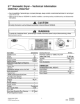
UPPER DRYING CABINET
R
R
MODEL MCE/MCG8000
R
W
T
Low
140º F
W
LOWER TUMBLE DRYER
W
W
T
Regular
Medium
V
150º F
145º F
DRYING CENTER SPECIFICATIONS
Uncrated Dimensions: 331 /2 "W x 29"d x 74"h
Crated Dimensions: 36.8"w x 31.3"d x 76.3"h
Uncrated Weight: 245 lbs.
Crated Weight: 260 lbs.
©2004 Maytag Services
1
16023137
Troubleshooting
!
WARNING
To avoid risk of electrical shock, personal injury or death; disconnect power and or shut off gas supply before
servicing, unless testing requires power.
Will Not Dry (Gas Models)
Poor Gas Ignition
When the dryer is operated on a heat setting, the igniter
should be energized and burner shall fire within 45
seconds at 120 VAC. The failure of a component in this
system will usually be indicated by one of three
symptoms:
Will Not Run
Will not start or run:
• All wires are hooked up to their corresponding
terminals.
• Dryer is plugged in.
• Blown fuse or circuit breaker.
• Door switch functional...door closed.
• Poor connection between membrane switch and
logic board, or faulty membrane switch. Use "Pd"
utility to check function of membrane switch.
• Faulty motor relay, use diagnostic utilities to
manually operate relay.
• Drive motor functional.
• Blown thermal fuse.
Motor runs/Tumbler will not turn:
• Belt off or broken/damaged.
• Idler tension spring too weak or stretched.
• Idler pulley jammed or stuck.
Runs a few minutes and then stops:
• Lint buildup around drive motor.
• Low voltage present.
• Blower impeller blocked in blower
housing.
• Drive motor - start switch contacts stuck closed.
Blows fuses or trips circuit breaker:
Electric Models
• The amperage readings are at 240 volts. One line
with 24 amps, and the other line with 21 amps. The
neutral line will be at 3 amps. If the above
amperages are present, then the house wiring, fuse
box or circuit breaker should be suspected.
• Shorted heating element to housing.
• Incorrect wiring or a wire shorting to ground.
• Drive motor winding shorting to ground.
Gas Models
• During ignition the dryer will draw 7 amps. With the
burner ON, the dryer will draw 3 amps. If the dryer is
drawing amperages above this, then the house
wiring, fuse box or circuit breaker is suspected to be
at fault.
• Igniter harness loose and shorted to base.
• Incorrect wiring or wire shorted to ground.
• Open centrifugal switch in motor.
• Drive motor winding shorting to ground.
Will Not Dry
Will not heat (motor runs):
• Open heating element.
• Hi-Limit trips easily or is open.
• Faulty Thermistor.
• Faulty Heater Relays.
• Drive motor centrifugal start switch not allowing
voltage to gas valve or heating element.
16023137
The igniter does not glow. If the igniter does not heat
up, remove power and using an ohmmeter, check the
following:
• Open flame sensor
• Open igniter
• Shorted booster coil
• Open wiring
Igniter glows - No gas ignition. If the igniter heats up
but the main burner flame is not ignited, remove power
and using an ohmmeter, check the following:
• Open secondary coil
• Open holding coil
• Open wire harness
The gas is ignited but the flame goes out. If a normal
ignition takes place and after a short while the flame
goes out, check for the following:
• Radiant sensor contacts opening
prematurely.
• Weak gas valve coil may open when
stressed by higher temperatures.
Improper drying/clothes wrinkled/ rough
texture/long dry time:
• Lint filter is not clean.
• Restriction in exhaust.
• Outside exhaust hood damper door stuck closed.
• Exhaust too long, too many elbows, flex ductwork
installed.
• Poor makeup air available for the dryer.
• Incorrect tumbler speed. Tumbler belt slipping.
• Blower impeller bound; check for foreign material in
blower area.
• Customer overloading dryer.
• Check clothing labels for fabric content and cycle
selected.
• Gas valve coil opens - weak point in coil opens when
stressed under heated conditions.
• Clothes too wet due to insufficient spin out by
washer.
• Faulty Sensor Bar. See Sensor Bar diagnostic
section.
2
©2004 Maytag Services
Component Testing Procedures
!
WARNING
To avoid risk of electrical shock, personal injury or death; disconnect power and or shut off gas supply before
servicing, unless testing requires power.
unused portion of the keypad are ignored and sound
the invalid selection chime.
Troubleshooting the Sensor-Dry circuit:
• Check for incorrect wiring of the electrical connector
at the electronic control board.
Dryer runs for 2 minutes, jumps to a 1-minute cool
down and then stops. Open Sensor Dry circuit.
Check Sensor Bar. Refer to Sensor Bar Diagnostics
section.
• Dryer does not shut off. Check sensor for continuity.
If found, replace sensor bar or clean with alcohol.
Some fabric softener sheets will coat the sensor
bars.
Note: Pressing the Off button exits the Diagnostic State
and places the control board in the Sleep State.
Diagnostic State Menu
Enter a menu item by using the Time Adjust cor d
arrows to see the letter code desired and press Signal
(+).
NOTE: * indicates a submenu with further explanation
given below.
Noisy and/Or Vibration
Menu
• Thumping. Check for loose tumbler baffle, rear
tumbler roller(s) worn or misaligned, out-of-round
tumbler or high weld seam on tumbler.
• Ticking. Check for loose wire harness or object
caught in blower wheel area.
• Scraping. Check for front or rear bulkhead felt seal
out of position or worn tumbler front bearings.
• Roaring. Check for blower wheel rubbing on blower
housing or bad motor bearings.
• Popping or squealing sound. Check for a sticky or
frayed belt.
cc
Factory Use Only
cd
Clear Diagnostic Codes
ch
Clear Help Codes
****dL
View Cycle Counts
View Diagnostic Code List
FS
Factory Use Only
hL
View Help Code List
Lo
Logic Board Output Self-test (Display will
show “PASS” “PASS” or “FAIL” “FAIL”
pc
Factory Use Only
*Pd
Membrane Key Pad Utility
**rd
Read Sensor Inputs
***Sc
Sub-system Check
SF
Software Version
rS
Reset to Factory Default Conditions
**rd Read Sensor Inputs
This utility allows the user to enable or disable the
display of sensor input values. Once enabled, the user
exits the Diagnostic State and the 7-segment display
used to make the selection alternates between the
sensor value and the time remaining. All other features
operate as normal. It is not necessary to start a cycle
for the sensor value to begin displaying. The user may
display lower dryer values on the upper dryer half of the
keypad with the converse also allowed.
To enter the Diagnostic State from the Normal Program
State on the upper or lower dryer half of the keypad,
press the Signal (+) button and Time Adjust ^
simultaneously for five (5) seconds. Upon entry to the
Diagnostic State, the corresponding 7-segment display
shows “dd”. Attempts to enter the Diagnostic State
while a dryer cycle is active causes the invalid selection
chime to sound.
After 10 minutes of inactivity the diagnostic state will be
canceled, and the machine will return to normal
operation. To exit the Diagnostic State, press the
Signal (-) button.
After exiting the Diagnostic State with the sensor
display function enabled, the 7-segment display
continuously cycles through a 4-step sequence. Each
step lasts 1.5 seconds. The sequence consists of the
following:
“n=” appears, to indicate that the next value is the time
remaining. The time remaining value appears on the
display.
Either half of the keypad may be used to request the
Diagnostic State. Once initiated, all key entries must be
made from the same half of the keypad. The LED
indicators and 7-segment displays on the remaining half
of the keypad are extinguished. Any key presses to the
©2004 Maytag Services
Beginning of Diagnostic State Menu
******cS
System Check Mode
The Diagnostic State provides a set of utilities not
intended for use by the consumer. Diagnostic State
utilities provide specialized functions for performance
evaluation and service. Upon recovery from a power
failure, the Drying Cabinet always returns to the
Normal-program State. Any Diagnostic State utility
active prior to the power failure is effectively cancelled.
Description
dd
3
16023137
Component Testing Procedures
!
WARNING
To avoid risk of electrical shock, personal injury or death; disconnect power and or shut off gas supply before
servicing, unless testing requires power.
“xx=” appears to indicate that the next value is from the
selected sensor. Where “xx.xx” is the item selected
from the sensor display menu. The sensor value
appears on the display.
***Sc Upper and Lower Dryer Sub-system Check
Utilities
To view the Sub-system Check Utility menu, scroll to
“Sc” on the main menu and press Signal (+).
Example:
1) To read measured temperature, scroll to “rd” on
the menu and press Signal (+).
2) Upon entry to the utility, “OFF” appears on the
display.
3) Using the Time Adjust d arrow button scroll to
“Ld” menu item from the Table.
Note: To exit the utility before running a test, press
Signal (-). The display will show “rd”. To exit
diagnostics press, Signal (-) again. The display will
show “dd”.
4) Press Signal (-) twice to initiate the menu item.
5) Time and Temperature are displayed.
6) Press “OFF” to exit the test.
To exit the Sub-system Check Utility Menu and return to
the Main Menu, press Signal (-) at any of the menu
items. Upon return to the Main Menu, “Sc” appears on
the display.
Upon entry to the Sub-system Check Utility Menu, “SU”
appears on the display.
Sub System Check Menu
Menu
Description
OFF
Ld
Sensor display disabled
Lower Dryer Outlet
Temperature
Upper Dryer Outlet
Temperature
Upper Dryer Door
Switch
Lower Dryer Heater
Energized
Lower Dryer Door
Switch
Lower Dryer Sensor Bar
Spare Thermistor Input
Ud
uS
LE
LS
*****db
SP
bo
Operate Upper Dryer Blower Motor
Operate Lower Dryer Motor
hr
Operate Upper Dryer Heater and Blower (Temp
displayed opposite side)
hh
NA
Degrees Fahrenheit
Operate Lower Heater and Blower at High Wattage
(Temp displayed opposite side)
hL
Operate Lower Heater and Blower at Low Wattage
(Temp displayed opposite side)
Degrees Fahrenheit
So
Operate Upper Dryer Shaker Motor
On or OFF (On = door open)
ho
Operate Upper Dryer Blower, Heater and Water Valve
d1
Unused
d2
Unused
Displayed Value
On or OFF (On = energized)
On or OFF (On = door closed)
Diagnostic Codes:
The diagnostic/help code information displayed
provides information about the machine. Any
abnormalities monitored by the board will be identified
as either a Help or Diagnostic code. Diagnostic Codes
will be logged and stored in permanent memory
(maximum nine in the list). A Diagnostic Code is logged
when there is a problem with the system. It may be
recommended the machine be serviced.
On or OFF (On = hit detected)
Degrees Fahrenheit
*Pd Membrane Keypad Utility
To select the Membrane Keypad utility, scroll to “Pd” on
the menu and press Signal (+).
Upon entry to the utility, all LED indicators and 7segment display LED elements illuminate. Pressing
each key extinguishes one or more of the keypad
indicators or 7-segment display LED elements. All the
keys must function properly to extinguish all the LED
elements. The LED extinguished may not be adjacent
to the keypad pressed. Do not press Signal (-) or you
will exit the utility.
Software checks for open or shorted thermistors and
door switch failures only during active cycles. Software
continuously checks for stuck button conditions.
“Stuck Button” fault detection uses the lower dryer cycle
count when logging a diagnostic code. Fault detection
logs a code once after initially detecting a fault. A fault
must clear before logging additional occurrences.
To exit the utility and return to the menu, press
Signal (-). Upon return to the Main Menu, display
shows “Pd”. To check Membrane Pad with ohm meter
see chart.
16023137
Beginning of Menu
Fd
Sensor Display Menu
Menu
Description
Su
****dL Accessing Diagnostic Codes
To view the Diagnostic Codes List, scroll to “dL” on the
menu and press Signal (+). Upon entry to the utility,
“SOL” appears on the display indicating start of list.
4
©2004 Maytag Services
Component Testing Procedures
!
WARNING
To avoid risk of electrical shock, personal injury or death; disconnect power and or shut off gas supply before
servicing, unless testing requires power.
Use the Time Adjust c (up arrow) and Time Adjust d
(down arrow) buttons to step through the list. The
display shows “End” after the last entry in the list is
reached. Attempts to step past the beginning or end of
the list will cause the invalid selection chime to sound.
Code
11
cd To select the Clear Diagnostic Codes utility, scroll
to “cd” on the menu and press Signal (+).
Upon entry to the utility, “cL” appears on the display.
Press Signal (+) again to clear all Diagnostic Codes for
both the upper and lower dryer. The message “AC”
appears on the display to indicate All Clear after the
clear function completes.
To exit the utility and return to the menu, press
Signal (-). Upon return to the Main Menu, “cd” appears
on the display.
Code
SOL
1
Description
Trigger
Start of list
Lower Dryer
Thermistor
Short Sensed
If temperature > 200
degrees for 2 minutes.
2
Lower Dryer
Thermistor
Open Sensed
3
Lower Dryer
Door Circuit
Failure
4
5
12
Upper Dryer
Thermistor
Open Sensed
If the temperature is
low with an increase
of temperature
expected, and no
increase occurring
after 3 minutes.
13
Upper Dryer
Door Circuit
Failure
Low for more than 1
second.
Non Volatile
Memory
8
Stuck Button
9
10
Check for:
- Clogged lint
screen.
- Restricted vent
system.
Failed thermistor
If the temperature is
Check for:
low with an increase of - Low ambient
temperature expected,
temperature in
and no increase
room (Below
occurring after 3
50°F/10°C).
minutes.
- Outside vent
damper is stuck
open in
wintertime.
Loose or open wire
terminals
Low for more than 1
Check for:
second.
- Loose or open
wire terminals in
Door Sense circuit.
Problem Detected with
integrity of parameters
stored in EEPROM
memory.
A button sensed as
pressed more than 75
seconds, is assumed
as stuck.
Step 1 From the Normal Program State, press the
Signal (+) button and Time Adjust c to enter
the Diagnostic State from the upper or lower
dryer keypad.
Step 2 Scroll to the “rS” display on the menu and press
Signal (+). The number “004” appears on the
display to indicate the number of remaining
steps needed to complete the reset sequence.
Step 3 Open and leave open the Lower Dryer Door.
The remaining step count decrements to “003”
on the display.
Step 4 Press the Time Adjust c and Time Adjust d
at the same time. The remaining step count
decrements to “002” on the display.
Step 5 Press the Temperature c and Time Adjust d
at the same time. The remaining step count
decrements to “001” on the display.
Step 6 Close the Lower Dryer Door. The remaining
step count decrements to “000” once the Factory
Default settings have been restored. The "Power On
Reset" sequence then executes.
Disregard
Check for:
- Run membrane
pad check and
replace console
w/membrane pad if
necessary.
The remaining step count resets to (4) and the invalid
selection chime sounds when any of the following
conditions occur:
Not Used
Not Used
©2004 Maytag Services
Action Taken
Check for:
- Failed hi-limit
thermostat on
steamer.
- Failed thermal fuse
on heater.
Failed thermistor
Check for:
- Low ambient
temperature in
room (Below
50°F/10°C).
- Check door vent
seals.
Loose or open wire
terminals on steamer
circuit.
Check for:
- Loose or open wire
terminals
To restore Factory Default settings for the dryer
controls, complete the following sequence within one
(1) minute.
Action Taken
Not Used
Not Used
6
Trigger
If temperature > 200
degrees for 2
minutes.
Diagnostic Codes
rS Reset to Factory Default Conditions
Description
Upper Dryer
Thermistor
Short Sensed
5
•
A reset step is performed out of sequence.
•
An unexpected key combination is entered.
•
The time window expires.
16023137
Component Testing Procedures
!
WARNING
To avoid risk of electrical shock, personal injury or death; disconnect power and or shut off gas supply before
servicing, unless testing requires power.
Opening the door to complete the first step marks the
beginning of the time window.
This function does not clear either of the upper or lower
dryer cycle counters. All other parameters stored in
non-volatile memory are returned to the Factory Default
values.
The Reset Utility functions the same regardless of
which half of the keypad it is initiated from. Once the
utility is initiated, all key combinations must be made
from the same half of the keypad used to initiate the
utility.
The Signal (-) key exits the Reset Utility and returns to
the “rS” display on the main menu. Pressing the Signal
(-) key any time prior to completion of the reset
sequence cancels the sequence and then returns to the
main menu.
*****db Sensor Bar Diagnostics
Enter The Diagnostic Utilities Menu
1) The controls will not enter the Diagnostic State if a
cycle is active or paused for either dryer. Push the
Off key to cancel an active or paused dryer cycle.
Push Time Adjust c and Signal (+) for 5 seconds.
“dd” appears in the display.
2) Use Time Adjust c and Time Adjust d to scroll
through the utility menu.
3) Scroll to “rd” and push Signal (+) to enter the
sensor display menu. “OFF” appears on the
display to indicate an input sensor has not been
selected yet for the Read Sensor Display Function.
4) Use Time Adjust c and Time Adjust d to scroll
through the input sensor menu.
5) Scroll to “db” to select the Dryness Bar input for
display.
6) With “db” shown on the display, exit the input
sensor menu by pushing Signal (-). “rd” appears in
the display.
7) Push Signal (-) again to exit the diagnostic utility
menu and view the sensor bar status.
8) The Display cycles “n=x:xx”, then “db = On” with
a short across the dryness bars or “db = OFF” with
an open circuit between the dryness bars.
9) The dryer may be operated as normal with the
Read Sensor Display active. The “n=x:xx” portion
of the alternating display is the normal time
remaining value for the dryer display.
10) The display shows “db = On” when damp clothing
makes contact with the sensor bars.
11) Either half of the membrane switch may be used to
display any input with the Read Sensor Display
Function. The half of the membrane switch used to
16023137
6
enable the Read Sensor Display function also
determines where the sensor display appears.
Cancel the Read Sensor Display Function
1) Push the Off key for the upper dryer to place the
upper dryer controls in the Sleep State. The Sleep
State extinguishes all the LED indicators and
numerical displays.
2) Push the Off key for the lower dryer to place the
lower dryer controls in the Sleep State.
3) Placing both upper and lower dryer controls in the
Sleep State cancels the Read Sensor Display
Function.
Codes Visible To The Consumer.
The following help codes could appear on the display
and may need further investigation.
1) “PF” A power failure occurred during an active or
paused cycle. Consumer may push the
"Start/Pause" key to resume the interrupted cycle or
push the "Off" key to cancel the interrupted cycle
and start over with a new cycle.
2) “HP” The thermistor reading is out of range and the
dryer cycle is interrupted. Consumer may push the
"Off" Key and attempt to run the cycle again. If the
condition persists, a service technician should
check for a thermistor malfunction or a wiring
problem with the thermistor circuit. Service
Technician view the Diagnostic Codes and look for
code 1 or 2. See Diagnostic Codes chart.
3) “h1” A temperature increase has not been
detected on the lower dryer and the dryer advances
to Cool-down. Consumer may check for a blocked
vent. Service Technician check for heater not
functioning, blocked vent, cool air leaking into drum,
poor seal between drum and blower, bad
connection on igniter sense signal to control board,
thermistor malfunction.
4) “h11” A shaker assembly neutral fault has been
detected. Shaker relay is de-energized and the
cycle continues as normal without the shaker.
Service Technician check for a bad connection in
neutral circuit to the shaker assembly.
“Wrinkle Prevent” This is not a fault code but a
normal operation signal. During the Wrinkle Prevent
phase of the cycle, the output animation shows 1
segment moving around the perimeter of the display.
During the continuous tumble portion of Wrinkle
Prevent, the animation is constant. After 20 minutes of
continuous tumble, the Wrinkle Prevent intermittent
phase begins where the dryer tumbles for 10 seconds
out of every 5-minute interval. During this phase the
display shows the segment moving, and stopping
momentarily. This pattern continues until the Wrinkle
Prevent phase ends.
©2004 Maytag Services
Component Testing Procedures
!
WARNING
To avoid risk of electrical shock, personal injury or death; disconnect power and or shut off gas supply before
servicing, unless testing requires power.
Membrane Pad Continuity Checks
Enter a menu item buy pressing Signal (+).
cS******View Cycle Statistics
Cycle Statistics Menu
Menu
cu
Lc
Lh
Uc
Uh
To view the Cycle Statistics scroll to “cS” the menu and
press Signal (+).
Upon entry to the utility “cu” appears indicating
beginning of menu. Scroll to the menu item you want to
view by pressing Time Adjust c or Time Adjust d.
Membrane shown with console tipped forward for service.
Pin
Number
J1A
Description
Beginning of Menu
Lower Dryer Cycle Count
Lower Dryer Cycle Hours
Upper Dryer Cycle Count
Upper Dryer Cycle Hours
12
12
1 1
2
1 12
1
1
J2A
J2B
J1B
Location
Upper Dryer Cycle Selection
Upper Dryer Cycle Selection
Upper Dryer Temp. Selection
Upper Dryer Adjust Drying
Time
Upper Dryer Adjust Drying
Time
Upper Dryer Options
Upper Dryer Options
Upper Dryer Options
Upper Dryer Commands
Upper Dryer Commands
Lower Dryer Cycle Selection
Lower Dryer Cycle Selection
Lower Dryer Cycle Selection
Lower Dryer Cycle Selection
Lower Dryer Temp. Selection
Lower Dryer Adjust Drying
Time
Lower Dryer Adjust Drying
Time
Lower Dryer Options
Lower Dryer Options
Lower Dryer Commands
Lower Dryer Commands
Audible Signal Volume
Audible Signal Volume
©2004 Maytag Services
Description
Dry Wet Clothes
Refresh Dry
Clothes
Up Arrow
Plug
Number
Plug Number
J2B
J2B
Pin Number
7,10
J2B
J2B
7,9
Increase Time
J2B
Decrease Time
Wrinkle Release
Remove Odor
Add Fragrance
Start/Pause
Off
Sensor Dry
Time Dry
Wrinkle Release
Air Fluff
Up Arrow
J2B
J2B
J2B
J2B
J2B
J1B
J1B
J1B
J1B
J1B
J1B
Up Arrow
5,10
8,12
7,12
7,11
6,11
5,11
6,12
5,12
5,12
6,12
7,12
8,12
7,9
5,9
J1B
Down Arrow
Wrinkle Prevent
Damp Dry Signal
Start/Pause
Off
Decrease Volume
Increase Volume
J1B
J1B
J1B
J1B
J1B
J1B
7
6,9
5,10
6,10
5,11
6,11
8,11
7,11
16023137
Component Testing Procedures
!
WARNING
To avoid risk of electrical shock, personal injury or death; disconnect power and or shut off gas supply before
servicing, unless testing requires power.
Logic Board Connectors
Connector
Name
Pin
Number
J1A
J1B
J2A
J2B
J3
1-12
1-12
1-12
1-12
1
2
3
4
5
6
7
8
1
2
3
1
2
3
4
5
6
7
8
9
J4
J6A
10
11
J10
J10A
12
1
2
3
4
1
2
3
4
5
6
16023137
Description
Voltage
Left Keypad connector A
Left Keypad connector B
Right Keypad connector A
Right Keypad connector B
Lower dryer thermistor
Lower dryer thermistor
Lower dryer moisture sensor
Lower dryer moisture sensor
Spare thermistor source
Spare thermistor return
Upper exhaust air thermistor
Upper exhaust air thermistor
L1 to upper door switch
Upper door switch to Lamp
Chassis ground to logic board
12 VDC power
Power Supply Common
24 VDC power
To shaker motor relay coil
To upper blower motor relay coil
To upper heater relay coil
To water valve relay coil
To spare relay coil
To upper exhaust damper relay
coil
To lower heater cycling relay coil
To lower heater center-tap relay
coil
To lower dryer motor relay coil
VCC from logic board
Serial transmit signal
Serial receive signal
Serial signal common
DC common
Reset Signal
Serial transmit signal for logic
board
VCC from logic board
Serial receive signal for logic
board
VPP from programmer box
8
12 VDC
12 VDC
12 VDC
12 VDC
5 VDC
5 VDC
24 VDC
24 VDC
5 VDC
5 VDC
5 VDC
5 VDC
120 VAC
120 VAC
Ground
12 VDC
Common
24 VDC
12 VDC
12 VDC
12 VDC
12 VDC
12 VDC
12 VDC
Comment/
Connector Part Number
DC connections to Power &
Relay Board.
12 VDC
12 VDC
12 VDC
5 VDC
5 VDC
5 VDC
DC GND
DC GND
5 VDC
5 VDC
5 VDC
5 VDC
©2004 Maytag Services
Component Testing Procedures
!
WARNING
To avoid risk of electrical shock, personal injury or death; disconnect power and or shut off gas supply before
servicing, unless testing requires power.
Connector
Name
J11A
Pin
Number
1
2
3
4
5
Description
Voltage
L1 for use on logic board
Upper door switch power to lamp
Lower door switch signal
Gas igniter sense signal
Neutral for switched 120 VAC
signals
120 VAC
120 VAC
120 VAC
120 VAC
120 VACN
Comment/
Connector Part Number
120 VAC connections to
power & relay board.
Relay Header Connections
Relay
Name
K9
K8
K7
Connector
Name
Description
Voltage
NO
L1 to relay
120 VAC
COM
L1 to lower dryer motor
120 VAC
NO
L1 to relay
240 VAC
COM
L1 to lower dryer heater center tap
240 VAC
NO
L1 to relay
240 VAC
COM
L1 to lower dryer
240 VAC
Power and Relay Board Connectors
Connector
Name
Pin
Number
J5
J6B
J7
Description
Voltage
1
2
3
4
1-12
L1 to shaker motor
L1 to upper cabinet lamp
Neutral to shaker & lamp assembly
Unassigned
See J6A in Logic Board
Connectors Table
120 VAC
120 VAC
120 VACN
1
2
3
4
5
Neutral to Power & Relay Board
L2 to Power & Relay Board
Gas Igniter Sense
Lower Door Switch
L1 to Power & Relay Board
©2004 Maytag Services
9
5 & 12
VDC
120 VACN
120 VAC
120 VAC
120 VAC
120 VAC
16023137
Component Testing Procedures
!
WARNING
To avoid risk of electrical shock, personal injury or death; disconnect power and or shut off gas supply before
servicing, unless testing requires power.
Connector
Name
J9
J11B
Pin
Number
1
2
3
4
5
Description
Voltage
Relay to upper blower motor
Unassigned
Unassigned
Unassigned
Relay connects upper heater to
L2
120 VAC
120 VAC
6
Unassigned
7
Spare relay output
120 VAC
8
Relay to water valve
120 VAC
9
Unassigned
10
Relay connects upper heater to
L2
See J11A in Logic Board
Connectors table
1-5
120 VAC
120 VAC
Note: VACN is the neutral wire of a 120V supply.
16023137
10
©2004 Maytag Services
Wiring Diagram and Schematic
!
WARNING
To avoid risk of electrical shock, personal injury or death; disconnect power to oven before servicing, unless
testing requires power.
MCE8000A
©2004 Maytag Services
11
16023137
Wiring Diagram and Schematic
!
WARNING
To avoid risk of electrical shock, personal injury or death; disconnect power and or shut off gas supply before
servicing, unless testing requires power.
MCG8000A
16023137
12
©2004 Maytag Services