1
Troubleshooting Procedures
!
WARNING
To avoid risk of electrical shock, personal injury or death, disconnect power to unit before servicing, unless testing
requires power.
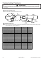
• Clothes too wet due to insufficient spin out by washer. Note: Pressing the Off button exits the Diagnostic State
• Faulty Sensor Bar. See Sensor Bar diagnostic section. and places the control board in the Sleep State.
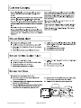
Troubleshooting the Sensor-Dry circuit:
• Check for incorrect wiring of the electrical connector at
the electronic control board.
Dryer runs for 2 minutes, jumps to a 1-minute cool
down and then stops. Open Sensor Dry circuit. Check
Sensor Bar. Refer to Sensor Bar Diagnostics section.
• Dryer does not shut off. Check sensor for continuity. If
found, replace sensor bar or clean with alcohol. Some
fabric softener sheets will coat the sensor bars.
Noisy and/Or Vibration
• Thumping. Check for loose tumbler baffle, rear
tumbler roller(s) worn or misaligned, out-of-round
tumbler or high weld seam on tumbler.
• Ticking. Check for loose wire harness or object
caught in blower wheel area.
• Scraping. Check for front or rear bulkhead felt seal
out of position or worn tumbler front bearings.
• Roaring - Check for blower wheel rubbing on blower
housing or bad motor bearings.
• Popping or squealing sound. Check for a sticky or
frayed belt.
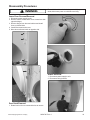
System Check Mode
The Diagnostic State provides a set of utilities not
intended for use by the consumer. Diagnostic State
utilities provide specialized functions for performance
evaluation and service. Upon recovery from a power
failure, the Drying Cabinet always returns to the Normalprogram State. Any Diagnostic State utility active prior to
the power failure is effectively cancelled.
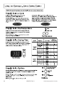
To enter the Diagnostic State from the Normal Program
State on the upper or lower dryer half of the keypad,
press the Signal (+) button and Time Adjust ^
simultaneously for five (5) seconds. Upon entry to the
Diagnostic State, the corresponding 7-segment display
shows “dd”. Attempts to enter the Diagnostic State while
a dryer cycle is active causes the invalid selection chime
to sound.
After 10 minutes of inactivity the diagnostic state will be
canceled, and the machine will return to normal
operation. To exit the Diagnostic State, press the Signal
(-) button.
Either half of the keypad may be used to request the
Diagnostic State. Once initiated, all key entries must be
made from the same half of the keypad. The LED
indicators and 7-segment displays on the remaining half
of the keypad are extinguished. Any key presses to the
unused portion of the keypad are ignored and sound the
invalid selection chime.
12
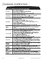
Diagnostic State Menu
Enter a menu item by using the Time Adjust ^or v
arrows to see the letter code desired and press Signal
(+).
NOTE: * indicates a submenu with further explanation
given below.
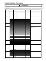
Menu
dd
Description
Beginning of Diagnostic State Menu
cc
Factory Use Only
cd
Clear Diagnostic Codes
ch
Clear Help Codes
******cS
View Cycle Counts
****dL
View Diagnostic Code List
FS
Factory Use Only
hL
View Help Code List
Lo
Logic Board Output Self-test (Display
will show “PASS” “PASS” or “FAIL”
“FAIL”
pc
Factory Use Only
*Pd
Membrane Key Pad Utility
**rd
Read Sensor Inputs
***Sc
Sub-system Check
SF
Software Version
rS
Reset to Factory Default Conditions
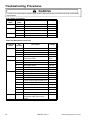
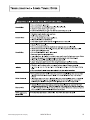
rd**Read Sensor Inputs
This utility allows the user to enable or disable the display
of sensor input values. Once enabled, the user exits the
Diagnostic State and the 7-segment display used to
make the selection alternates between the sensor value
and the time remaining. All other features operate as
normal. It is not necessary to start a cycle for the sensor
value to begin displaying. The user may display lower
dryer values on the upper dryer half of the keypad with
the converse also allowed.
After exiting the Diagnostic State with the sensor display
function enabled, the 7-segment display continuously
cycles through a 4-step sequence. Each step lasts 1.5
seconds. The sequence consists of the following:
“n=” appears to indicate that the next value is the time
remaining. The time remaining value appears on the
display.
“xx=” appears to indicate that the next value is from the
selected sensor. Where “xx.xx” is the item selected from
the sensor display menu. The sensor value appears on
16022785 Rev. 0
©2003 Maytag Appliances Company