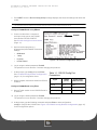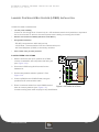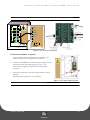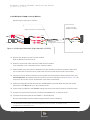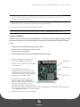
1
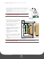
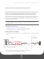
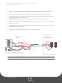
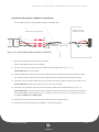
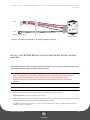
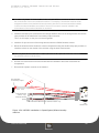
LC3000 Laundry Reader
Installation and Setup Guide
The following information applies to wired LC3000 systems equipped with LCM20s only.
Blackboard Inc.
LC3000
Tested To Comply
With FCC Standards
FOR HOME OR OFFICE USE
This Class A digital apparatus complies with
Canadian ICES-003
The following information applies to wireless systems equipped with LWIs and LE3/BRIDGES only.
Blackboard Inc.
LWI30xx
Tested To Comply
With FCC Standards
FOR HOME OR OFFICE USE
This device complies with Part 15 of the FCC Rules. Operation is subject to the following two conditions: (1) This
device may not cause harmful interference, and (2) this device must accept any interference received, including
interference that may cause undesired operation.
Part 15.21: Changes or modifications not expressly approved by the party responsible for compliance could void the user’s
authority to operate the equipment.
NOTE: The manufacturer is not responsible for any radio or TV interference caused by unauthorized modifications to this
equipment. Such modifications could void the user’s authority to operate the equipment.
Date: 10/6/09 Doc. No.: 1135
Copyright © 2005 Blackboard Inc.® All rights reserved. No part of this publication may be
reproduced or used in any form or by any means—graphic, electronic, or mechanical including
photocopying, recording, taping, or information storage and retrieval systems—without the
express written permission of Blackboard Inc. Information contained in this document is subject to
change without notice.
Contents
1 LC3000 LAUNDRY CENTER INSTALLATION
4
4
Laundry Center Components
LC3000 Components
5
Laundry Center Installation Overview
6 LC3000 LAUNDRY READER INSTALLATION
7
Install the LC3000 Enclosure
9
10
11
11
LC3000 Laundry Reader Configuration
Configure LC3000 Reader using front panel
Configure LC3000 Reader using RS-232
Configure LC3000 Reader using Telnet
12 Comm Mode Selection
13 WIRED LAUNDRY MACHINE INTERFACE INSTALLATION
15 Laundry Controller Multiplexer (LCM20) Installation
15 Install the LCM20 in the LC3000
16 Install External LCM20(s) (if required)
18
18
20
21
Laundry Controller Interface (LCI) Installation
Install Maytag LCI3010 in Laundry Machine
Install Alliance/Speed Queen LCI3020 in Laundry Machine
Install Whirlpool LCI3030 in Laundry Machine
22 WIRELESS LAUNDRY MACHINE INTERFACE INSTALLATION
23 Wireless Bridge LE3/BRIDGE Installation
23 Configure the LE3/BRIDGE
24 Install the LE3/BRIDGE
25 Laundry Wireless Interface Module (LWI) Installation
25 Configure the LWI Module
26 Install the LWI Module
27 Install the LWI3010 Module for Maytag laundry machines
28 Install the LWI3020 Module for Alliance/Speed Queen laundry machines
30 Wireless Module Troubleshooting and Operation
PRINTED OCTOBER 6, 2009
I
Contents
32 APPENDIX
32 Features
33 Transaction Process
35 Manager Menus
37 Laundry Components Dimensions and Weight
40 LC3000 Laundry Reader Default Configuration Settings
40 Restore Default Settings
41 MW9010/MW9012 Laundry Reader Retrofit
41 Configure LC3000 for retrofit (wired laundry centers only)
PRINTED OCTOBER 6, 2009
II
Figures
Figure 1-1
Wired LC3000 Laundry Center Solution2
Figure 1-2
Wireless Laundry Center Solution3
Figure 1-3
Mounting & Knockouts7
Figure 1-4
Power Installation7
Figure 1-5
Power Connections8
Figure 1-6
LC3000 Laundry Reader Configuration10
Figure 1-7
Front panel configuration10
Figure 1-8
LC3000 Configuration Menu11
Figure 1-9
LC3000 Laundry Center Solution14
Figure 1-10
LCM20 in LC300015
Figure 1-11
LCM20 Connections16
Figure 1-12
Power Supply access16
Figure 1-13
Power Connections17
Figure 1-14
LCM20 and LE3/PSENCL Connections17
Figure 1-15
Single Maytag Machine18
Figure 1-16
Maytag Stacked Machine19
Figure 1-17
Alliance/Speed Queen Machine (LCI3020)20
Figure 1-18
Whirlpool/Advantech Single Machine (LCI3030)21
Figure 1-19
Wireless Laundry Center Solution22
Figure 1-20
Bridge Connections23
Figure 1-21
Wireless Bridge24
Figure 1-22
LWI wireless module27
Figure 1-23
LWI3010 installation in Maytag laundry machine28
Figure 1-24
LWI3020 installation in Speed Queen/Alliance laundry machine29
Figure 1-25
Bridge Module LEDs30
Figure 1-26
LWI Module LEDs31
Figure 1-27
Manager Menus35
Figure 1-28
LC3000 Dimensions37
PRINTED OCTOBER 6, 2009
III
LC3000 LAUNDRY READER INSTALLATION GUIDE
D OCUMENT 1 1 3 5
REV 03
LC3000 L AUNDRY C ENTER I N S TALL A T IO N
This manual provides instructions for selecting, installing, and configuring
the Blackboard Laundry Center using the LC3000 Laundry Reader.
The LC3000 Laundry Reader controls laundry machines across a laundry
Center network and Blackboard Transaction System (BbTS) and
communicates with the user interface through a display, keypad, and magstripe reader. The network connections are 10/100 Base-T or RS-485,
machine connections are wired or wireless.
Laundry Readers connecting to a Universal Edition Host in RS-485 mode require an IP
Converter (IPC).
Universal Edition Hosts using RS-485 network connections do not support wireless
communications with laundry machines.
PRINTED OCTOBER 6, 2009
1-1
LC3000 LAUNDRY CENTER INSTALLATION
WIRED SOLUTION
The wired solution reader supports up to 60 laundry machines across three connected Multiplexers. The
first Multiplexer is installed inside the LC3000.
Each machine uses a Laundry Controller Interface (LCI), a wiring harness inside the machine, to facilitate
communications between the laundry machine controller and LC3000 Laundry Reader.
Campus
Network
Belden 8723, 5502UE cable
or equivalent
Laundry Reader (LC3000)
w/ Multiplexer (LMC20)
Multiplexer (LCM20)
w/ Enclosure (LE3/PSENCL)
Multiplexer (LCM20)
w/ Enclosure (LE3/PSENCL)
Belden 8723, 5502UE cable
or equivalent
(400’ max)
1 ---------------------- 20
21 -------------------- 40
41 --------------------
60
Laundry Controller Interface (LCI) inside each machine
Figure 1-1 Wired LC3000 Laundry Center
PRINTED OCTOBER 6, 2009
1-2
LC3000 LAUNDRY READER INSTALLATION GUIDE
D OCUMENT 1 1 3 5
REV 03
WIRELESS SOLUTION
Up to 60 laundry machines can be connected wirelessly to the LC3000 using a Wireless Bridge (LE3/
BRIDGE). Each Bridge communicates with laundry machines within 60 feet. Multiple Wireless Bridges can
be used if stone or metal obstructions reduce the range. Each laundry machine connects to a Laundry
Wireless Interface installed inside the machine. The Laundry Wireless Interface (LWI), a wiring harness
and wireless module, facilitates communications between a laundry machine and the LC3000 Laundry
Reader, via the Wireless Bridge.
Campus
Network
Belden 5502UE cable
or equivalent
Wireless Bridge (LE3/BRIDGE)
Laundry Reader (LC3000)
(machines 1 - 60)
(60 feet)
1 ------------------------------------------ 60
Laundry Wireless Interface (LWI) installed in each machine
Figure 1-2 Wireless Laundry Center Solution
PRINTED OCTOBER 6, 2009
1-3
LAUNDRY CENTER COMPONENTS
LAUNDRY CENTER C OMPONENTS
LC3000 Components
COMMON COMPONENT
Laundry Reader LC3000
Each LC3000 supports up to 60 machines (stacked units count as 2 machines).
Wired installations require LCM20(s) and LCIs.
Wireless installations require LE3/BRIDGE(s) and LWI(s).
WIRED COMPONENTS
Laundry
Controller
Multiplexer
LCM20
Power Supply /
Enclosure
LE3/PSENCL An LE3/PSENCL power supply/enclosure is required for the 2nd and 3rd LCM20s. A
2nd LCM20 is required if the LC3000 is controlling more than 20 machines, a 3rd
LCM20 is required if the LC3000 is controlling more than 40 machines.
Interfaces
Maytag
LCI3010
Speed Queen LCI3020
Whirlpool
LCI3030
Each LCM20 supports 20 wired machines. The first LCM20 is installed inside the
LC3000. The second and third LCM20s each require a Power Supply Enclosure
(LE3/PSENCL).
All Maytag commercial debit-card ready machines are supported by the LCI3010. An
LCI3010 is required for each single machine or for a complete stacked unit (both top
and bottom unit supported by a single LCI3010).
Only Speed Queen NetMaster and MDC models are supported by the LCI3020. An
LCI3020 is required for each single machine. Two LCI3020s are required to support a
stacked unit.
Only Whirlpool Advantech models are supported by the LCI3030. A LCI3030 is
required for each single machine. Two LCI3030s are required to support a stacked
unit.
WIRELESS COMPONENTS
Interfaces
Wireless Bridge
LE3/BRIDGE Each LE3/BRIDGE is the hub of a wireless network for up to 60 machines. The LE3/
BRIDGE needs to be no further than 60 feet from each of the machines on its
wireless network. The LE3/BRIDGE connects to the LC3000 via a standard CAT5
patch cable.
Maytag
LWI3010
All Maytag commercial debit-card ready machines are supported by the LWI3010. A
LWI3010 is required for each single machine or for a complete stacked unit (both top
and bottom units are supported by a single LWI3010).
Speed Queen LWI3020
Speed Queen NetMaster and MDC models are supported by the LWI3020. A
LWI3020 is required for each single machine or for a complete stacked unit (both top
and bottom units are supported by a single LWI3020).
PRINTED OCTOBER 6, 2009
1-4
LC3000 LAUNDRY READER INSTALLATION GUIDE
D OCUMENT 1 1 3 5
REV 03
LAUNDRY CENTER I NSTALLATION O VERVIEW
1
Configure Laundry Machines in BbTS.
(see BbTS Universal System Administration Guide)
(see BbTS Unix Reference Manual)
2
LC3000 Laundry Reader Installation (page 1-6)
3
LC3000 Laundry Reader Configuration (page 1-9)
LC3000Config
MAC Address
IP Address
DHCP Status
IP Communications
RS-485Communications
Communication
Mode
Reader Address
Baud Rate
Enabled
DHCP
HostDHCP
T elnetEnable
Servic e Card
Enable
Dis abled
Disable
IP Address
Save
Subnet Mask
Default Router/
Gateway
4
Hos t IP Address
Wired Laundry Machine Interface Installation (page 1-13) or Wireless Laundry Machine Interface
Installation (page 1-22)
PRINTED OCTOBER 6, 2009
1-5
LC3000 LAUNDRY READER INSTALLATION
LC3000 L AUNDRY R EADER I NSTA LLATION
The LC3000 Laundry Reader must be mounted on a wall in a location that is convenient to cardholders
and wiring requirements.
LC3000 MOUNTING LOCATION CONSIDERATIONS
•
120 VAC power availability
Connect to 120 VAC @ 60 Hz. Connect only to a 15A maximum branch circuit protection or equivalent.
Use a circuit breaker or switch to disconnect power when installing or removing the LC3000.
•
Network communications availability (RS-485 or 10/100 Base T)
•
Wiring distance limitations
- RS-485 Communications 4000' total per loop
- 10/100 Base-T Communications 300' from the network switch port
•
Ease of cable routing to laundry machines (if wired configuration)
•
Installation height regulations
•
Cardholder convenience
Mounting hardware required: .25” appropriate to surface.
PRINTED OCTOBER 6, 2009
1-6
LC3000 LAUNDRY READER INSTALLATION GUIDE
D OCUMENT 1 1 3 5
REV 03
PREPARE ENCLOSURE
The Reader can be mounted flush to the wall with
wiring behind the wall; or it can be surface-
AC power knockouts
machine wires
flush-mount
mounted with wiring in conduit exterior of the wall.
Before mounting the enclosure, remove knockouts
ACMAIN
necessary for routing wires and/or attaching
conduits. Remove only the knockouts required for
your installation.
•
AC power knockouts accept 1/2'' conduit fittings.
•
All other knockouts accept 3/4'' conduit fittings.
Flush-mount: route machine wires, if wired,
through the 3'' x 3'' cutout.
use side
knockouts
only if
surface
mounting
Surface-mount: Remove conduit knockouts
on the top and bottom of the enclosure for
routing wire to machines.
•
Mount
Mount
Figure 1-3 Mounting & Knockouts
Two power knockouts are provided in the upper
right.
Flush-mount: Remove the knockout on the
back side.
Surface-mount: Remove the knockout on the
top.
Install the LC3000 Enclosure
5
Inside the LC3000, remove the power supply cover to
access the upper right mounting hole.
Protect power supply from debris while mounting the
enclosure.
6
Secure enclosure to a wall using hardware appropriate to
wall material.
Mounting holes accept up to 1/4'' hardware.
Disconnect external AC power when installing wiring.
Figure 1-4 Power Installation
7
Strip back insulation on AC wire .28" to prevent bare wire
exposure when installed in AC terminal block.
PRINTED OCTOBER 6, 2009
1-7
LC3000 LAUNDRY READER INSTALLATION
8
Install wires into the AC terminal block as shown in Figure 1-5,
tighten the screws to 5 - 7 in-lbs., and replace power supply cover.
Ensure 120VAC wiring is confined within power supply
compartment when cover is reinstalled to maintain UL
compliance.
9
Line
Neutral
Ground
Reconnect external AC power.
10 Connect to Network.
The LC3000 provides for both 10/100 Base-T, TCP/IP and RS-485
BbTS network connections.
Figure 1-5 Power
Connections
Once connected, configure the LC3000. See: the LC3000 Laundry Reader Configuration
(page 1-10).)
PRINTED OCTOBER 6, 2009
1-8
LC3000 LAUNDRY READER INSTALLATION GUIDE
D OCUMENT 1 1 3 5
REV 03
LC3000 L AUNDRY READER C ONFIGURATION
The Laundry Reader must be configured to communicate with the BbTS network.
LC3000 DEFAULT CONFIGURATION
•
DHCP enabled
•
NP (host) IP address assigned by DHCP server
CONFIGURATION METHODS
Configure the LC3000 Laundry Reader to interface with BbTS, using one of three modes:
•
Configure LC3000 Reader using front panel (page 1-10)
•
Configure LC3000 Reader using RS-232 (page 1-11)
The Reader’s RS-232 can be used to connect to a computer using Hyperterminal
•
Configure LC3000 Reader using Telnet (page 1-11)
The Reader can be configured via IP if using Ethernet connections once it is assigned an IP address.
PRINTED OCTOBER 6, 2009
1-9
LC3000 LAUNDRY READER CONFIGURATION
LC3000Config
Figure 1-6 LC3000 Laundry Reader
MAC Address
IP Address
DHCP Status
IP Communications
RS-485Communications
Communication
Mode
Reader Address
BaudRate
Enabled
DHCP
HostDHCP
TelnetEnable
Service Card
Enable
Disabled
Disable
IP Address
Save
Subnet Mask
Default Router/
Gateway
Host IP Address
OFFLINE: An asterisk (*) in the first line, second to the last position indicates the terminal is
offline.
Configure LC3000 Reader using front panel
1
Swipe a Service Card, and then press NEXT to start the configuration
process.
2
Adjust each setup parameter using the keys displayed on the
Terminal.
ACCEPT - Accept displayed value and advance to next setting.
CHANGE - Change displayed value.
ABORT - Abort configuration process.
To update the IP address and related information, press CHANGE
when the parameter is displayed; then type the number using zeroes
(0) as placeholders.
PRINTED OCTOBER 6, 2009
Figure 1-7 Front panel
configuration
1-10
LC3000 LAUNDRY READER INSTALLATION GUIDE
D OCUMENT 1 1 3 5
3
REV 03
Press NEXT when the End of Config Setup message displays, this saves the settings and reboot the
reader.
The terminal may be offline for several minutes until it synchronizes with the Host.
Configure LC3000 Reader using RS-232
4
Connect a cable from a computer’s
serial port to the port on the LC3000
door labelled “RS-232 CONFIG”.
IPrdr4U
See: RS-232 Config Port Connections
(Page: 11).
5
6
Open a terminal program (e.g.
Hyperterminal) and establish connection
settings:
•
9600 baud
•
1 stop
•
no parity
•
no flow control
Figure 1-8 LC3000 Configuration Menu
Log in using the default password: IPrdr4U.
The password is case sensitive. Consider changing the password.
7
At the prompt, type config and press Enter.
See: LC3000 Laundry Reader Configuration
(page 1-10) for configuration items.
8
When complete, disconnect cable from RS-232
CONFIG.
Configure LC3000 Reader using Telnet
9
Open a Telnet session to the LC3000 Reader’s
IP address.
Table 1-1: RS-232 Config Port
Connections
Signal
LC3000
(RJ-12)
PC Serial Port
DB9 Connector
Ground
Pin 1
Pin 5
Receive (RX)
Pin 3
Pin 3
Transmit (TX)
Pin 4
Pin 2
10 Log in using the default password: IPrdr4U.
The password is case sensitive. Consider changing the password.
11 At the prompt, type the following command and press Enter to start configuration:
config to configure the LC3000. See: Figure 1-6 LC3000 Laundry Reader Configuration (page 10)
for the configuration options.
PRINTED OCTOBER 6, 2009
1-11
COMM M ODE SELECTION
COMM MODE S ELECTION
OVERVIEW
The ‘Comm Mode’ selections on the CR3000, LC3000 and VR/MDBMP have been changed a few times in
the history of the products.
When a given communication mode is selected, the unit reboots and starts a specific software executable
type based on the communication mode chosen. Because the readers have 3 different software types
loaded in them (and they can be individually updated when the unit comes online with a host), it is possible
for the same unit to display different ‘Comm Mode’ selections depending on the current selection (and thus
the current software type running).
SUMMARY
To correctly select the ‘Comm Mode’ for a CR3000, LC3000 or VR/MDBMP, you must determine which
Selection List the currently running software has (by cycling through all the choices), then make the correct
selection for the communication protocol you wish to use.
CR3000, LC3000 and VR/MDBMP ‘Comm Mode’ selections:
Unix/Bb RS-485
protocol
Bb IP/Ethernet protocol
Danyl
protocol
Selection list 1
RS-485
Ethernet
---
Selection list 2
485-UE
IP
485-WE
Selection list 3
485-Unix
IP
485-UE
Selection list 4
485-Bb
IP
485-Danyl
PRINTED OCTOBER 6, 2009
1-12
LC3000 LAUNDRY READER INSTALLATION GUIDE
D OCUMENT 1 1 3 5
REV 03
W IRED L AUNDRY M ACHINE I NTERFACE
I NSTALLATION
WIRED INSTALLATION OVERVIEW
•
Install the LCM20 in the LC3000 (page 1-15)
•
Install External LCM20(s) (if required) (page 1-16)
Only laundry centers with more than 20 laundry machines need External LCM20s. Each LCM20
communicates with up to 20 laundry machines.
•
Laundry Controller Interface (LCI) Installation (page 1-18)
The wired Blackboard laundry solution supports up to 60 laundry machines. Multiplexers (LCM20s)
facilitate up to 20 wired machine connections each. In laundry centers with 20 or fewer machines, a single
Multiplexer is installed inside the LC3000 enclosure. Laundry Centers supporting more than 20 machines
require additional Multiplexers and enclosures for mounting, power and protection. Order an enclosure,
LE3/PSENCL, for each additional Multiplexer. The Reader supports three (3) Multiplexers.
Each Multiplexer connects to 20 machines, using a Laundry Controller Interface installed inside the
machine. The Laundry Controller Interface (LCI) is a wiring harness that communicates with the laundry
machine controller.
PRINTED OCTOBER 6, 2009
1-13
WIRED LAUNDRY MACHINE INTERFACE INSTALLATION
Campus
Network
Belden 8723, 5502UE cable
or equivalent
Laundry Reader (LC3000)
w/ Multiplexer (LMC20)
Multiplexer (LCM20)
w/ Enclosure (LE3/PSENCL)
Multiplexer (LCM20)
w/ Enclosure (LE3/PS
n 8723, 5502UE cable
uivalent
max)
1 ---------------------- 20
21 -------------------- 40
41 --------------------
60
Laundry Center Interface (LCI) installed in each machine
Figure 1-9 LC3000 Laundry Center Solution
PRINTED OCTOBER 6, 2009
1-14
LC3000 LAUNDRY READER INSTALLATION GUIDE
D OCUMENT 1 1 3 5
REV 03
LAUNDRY CONTROLLER MULTIPLEXER (LCM20) INSTALLATION
LCM20 PLACEMENT CONSIDERATIONS
•
120 VAC power availability
Connect to 120 VAC @ 60 Hz. Connect only to a 15A maximum branch circuit protection or equivalent.
Use a circuit breaker or switch to disconnect power when installing or removing the LC3000.
•
Network communications availability (RS-485 or 10/100 Base-T)
•
Wiring distance limitations
- RS-485 Communications 4000' total per loop
- 10/100 Base-T Communications 300' from network switch port
- 400' from Multiplexer (LCM20) to the laundry machines
•
Ease of cable routing to laundry machines
Install the LCM20 in the LC3000
1
E
D
C
B
A
With the enclosure door open, position the LCM20
over the six standoffs, with component side facing out
(see: Figure 1-10).
2
Secure the LCM20 using #4-40 screws from the
hardware kit.
3
Set the rotary address switch to position 0. See:
Figure 1-10.
4
Connect LCM20 to the LC3000 Reader, using the
provided RJ-45 communication cable.
5
Route 4-conductor cables from each LCM20 terminal
block to a laundry machine (see: Figure 1-11).
F 0 1
2
98 7
3
4
5
6
ACMAIN
LNG
Figure 1-10 LCM20 in LC3000
Consider marking each cable uniquely for easy identification.
PRINTED OCTOBER 6, 2009
1-15
LAUNDRY CONTROLLER M ULTIPLEXER (LCM 20) INSTALLATION
Do not connect power to the LCM20 Board until all machine interfaces are terminated.
0
EF 1 2
3
D
C
4
B
5
A9
6
87
ACMAIN
LNG
LINK/ACT
NET
100M
HOST RS-485
LCM20 RS-485
BRIDGE RS-485
AUX RS-485
Power
RS-232
LWI
CONFIG CONFIG
to external LCM20
(Belden 5502UE cable or equivalent)
Figure 1-11 LCM20 Connections
Install External LCM20(s) (if required)
If your Laundry Center has more than 20 machines, an
external LCM20 and LE3/PSENCL are required.
6
Inside the LE3/PSENCL, remove the power supply cover to
access the upper right mounting hole (Figure 1-12).
Protect power supply from debris while mounting the
enclosure.
7
Secure the enclosure to the wall using hardware for wall
material.
Mounting holes accept up to 1/4” hardware.
Figure 1-12 Power Supply access
Disconnect external AC power when installing wiring.
PRINTED OCTOBER 6, 2009
1-16
LC3000 LAUNDRY READER INSTALLATION GUIDE
D OCUMENT 1 1 3 5
8
REV 03
Strip back AC wire insulation .28", install wires into AC terminal block
as shown in Figure 1-13, tighten screws to 5-7 in-lbs., and replace
power supply cover.
Line
Neutral
Ground
Prevent bare wire from being exposed when installed in the AC
terminal block.
UL compliance: Ensure 120VAC wiring is within power supply
compartment when cover is replaced.
Figure 1-13 Power
Connections
9
Position LCM20, component side facing out,
over the six standoffs, and secure using the
#4-40 screws from the hardware kit.
E
D
C
B
A
F 0 1
2
98 7
10 Set rotary address switch to position 1 or 2.
EF
D
C
B
A9
Position 1: machines 21 - 40
Position 2: machines 41 - 60.
11 Route Belden cable from external LCM20 to
LCM20 mounted inside the LC3000
enclosure.
3
4
5
6
01
2
3
4
5
6
87
power
ACMAIN
LNG
rotary
switch
(set to
1 or 2)
Refer to LCM20 and LE3/PSENCL
Connections (page 1-17) for cable
termination.
12 Route a 4-conductor cable from each laundry
machine to an LCM20 terminal block (TB1 TB20).
Consider marking cables uniquely for easy
identification.
to LCM20 in LC3000
(Belden 5502UE cable or equivalent)
Figure 1-14 LCM20 and LE3/PSENCL
Connections
Do not connect LCM20 power until all machine interfaces are terminated at both the
laundry machine and the LCM20.
PRINTED OCTOBER 6, 2009
1-17
LAUNDRY CONTROLLER INTERFACE (L CI) INSTALLATION
LAUNDRY CONTROLLER I NTERFACE (LCI) I NSTALLATION
The Laundry Controller Interface (LCI) is installed inside each laundry machine. The Laundry Controller
Interface (LCI) is a wiring harness that connects to the laundry machine controller. The LCI is then
connected to the Laundry Controller Multiplexer (LCM20) to communicate with Laundry Reader.
The Laundry Controller Interface (LCI) model used depends on the laundry machine manufacturer. See:
Laundry Center Components (page 1-4) for Laundry Machine Interface (LCI) models. Each model
includes cables, splices and wire ties.
To prevent tampering, run cable through flexible metal conduit from LCM20 to the back of the
machine. If flexible metal conduit is not used, then a strain relief must be used to prevent
damage to the cable.
LCI Installation instructions included are:
•
Install Maytag LCI3010 in Laundry Machine (page 1-18)
•
Install Alliance/Speed Queen LCI3020 in Laundry Machine (page 1-20)
•
Install Whirlpool LCI3030 in Laundry Machine (page 1-21)
Install Maytag LCI3010 in Laundry Machine
Two cables are included to support stacked dryers. If installing a single machine, discard the two-wire
cable.
Washing Machine
Maytag
6-pin Molex
6
5
4
3
2
1
Laundry Controller
Multiplexer (LCM20)
black
red
red
white
white
black
black
1
2
black 3
white 4
red
BELDEN 8723
or equivalent 4-conductor cable
green
green
Figure 1-15 Single Maytag Machine
1
Remove the operator console (with display and switches) from the machine.
Only the screws in the top two corners need to be removed.
PRINTED OCTOBER 6, 2009
1-18
LC3000 LAUNDRY READER INSTALLATION GUIDE
D OCUMENT 1 1 3 5
REV 03
2
Route the 4-conductor cable from the LCM20 into the laundry machine for connection to the LCI.
3
Attach female connectors from the hardware kit to the machine end of the 4-conductor cable.
4
Insert the LCI male bullet connectors into the female connectors of the 4-conductor cable (white to
white, black to black, etc.) see: Figure 1-15.
Stacked Machine: connect the two-wire harness to the black and green wires, as shown.
5
Install the LCI into the machine circuit board’s six-pin Molex (see: Figure 1-16), and if a stacked dryer,
adjacent 2-pin Molex.
6
Use the wire ties and wire tie blocks included in the hardware kit to dress the wires, and replace the
laundry machine operator console.
7
Terminate the 4-conductor cable at the LCM20 1 x 4 terminal block(s).
6-pin Molex
Stacked Dryer
Maytag
6
5
4
3
2
1
Laundry Controller
Multiplexer (LCM20)
black
red
red
white
white
black
2
1
1
black
green
BELDEN 8723
or equivalent 4-conductor cable
red
2
black 3
white 4
1
2
3
4
green
Figure 1-16 Maytag Stacked Machine
Switch the green and white wires if the signals do not correspond to the machines as labeled.
PRINTED OCTOBER 6, 2009
1-19
LAUNDRY CONTROLLER INTERFACE (L CI) INSTALLATION
Install Alliance/Speed Queen LCI3020 in Laundry Machine
Two LCI3020s must be ordered when wiring to a stacked dryer.
Laundry Controller
Multiplexer (LCM20)
Speed Queen Laundry Machine
white
4-pin Molex
4 black
3
red
2
black
1
white
1
2
black 3
white 4
red
red
black
BELDEN 8723
or equivalent 4-conductor cable
green
green
Figure 1-17 Alliance/Speed Queen Machine (LCI3020)
8
Remove the operator console from the machine.
Refer to the Speed Queen service manual.
9
Route the 4-conductor cable from the LCM20 into the machine (see: Figure 1-17).
Stacked Machine: run two cables.
10 Attach female bullet connectors from the hardware kit to the machine end of the 4-conductor cable.
Use a strain relief or other means to protect and secure the cable where it enters the machine.
11 Insert the LCI male bullet connectors into the female connectors. (white to white, black to black, etc.).
Stacked Machine: perform the same process on the second cable.
12 Insert the four-pin Molex connector into the machine circuit board, as illustrated in Figure 1-17.
Stacked Machine: insert the second four-pin Molex connector into the second machine circuit board.
Some Speed Queen machines have a 1 x 7 header; in this case, the LCI 1 x 4 header fits onto pins 1 4, labelled START IN and AVAIL OUT.
13 Use the wire ties and blocks included in the hardware kit to dress the wires.
14 Terminate 4-conductor cable at the LCM20 1 x 4 terminal block(s).
PRINTED OCTOBER 6, 2009
1-20
LC3000 LAUNDRY READER INSTALLATION GUIDE
D OCUMENT 1 1 3 5
REV 03
Install Whirlpool LCI3030 in Laundry Machine
Stacked dryers require two LCI3030s.
Laundry Controller
Multiplexer (LCM20)
Whirlpool Advantech Laundry Machine
1
2
black 3
white 4
black
M2
red
red
white
COIN 1
green
BELDEN 8723
or equivalent 4-conductor cable
green
Figure 1-18 Whirlpool/Advantech Single Machine (LCI3030)
15 Remove the operator console from the machine.
Refer to Whirlpool service manual.
16 Route the 4-conductor cable from the LCM20 into the machine.
If the installation is for a stacked machine, route two cables.
17 Attach female connectors from the hardware kit to the machine end of the 4-conductor cable wires.
Use a strain relief or other means to protect and secure the cable where it enters the machine.
18 Insert the LCI male bullet connectors into the female connectors (white to white, black to black, etc.).
Stacked Machine: the additional two-wire harness must be connected as shown in Figure 1-18. The
second LCI fits into the second, independent circuit board as illustrated.
19 Attach the orange wire female disconnect to the M1 spade lug and the black wire with the female
disconnect to the M2 spade lug on the controller board.
20 Connect the 4-pin Molex to the COIN #1 mating connector on the laundry machine controller board.
21 Use the wire ties and wire tie blocks, included in the hardware kit, to dress the wires.
22 Terminate 4-conductor cable at the LCM20 1 x 4 terminal block.
Be sure terminal block numbers match laundry machine numeric identifiers.
The Whirlpool control board must be configured for the coin drop, in addition to the
configuration for the BbTS host.
PRINTED OCTOBER 6, 2009
1-21
WIRELESS LAUNDRY MACHINE INTERFACE INSTALLATION
W I R E L E S S L AUNDRY M A C H I N E I NTERFACE
I NSTALLATION
WIRELESS LAUNDRY CENTER INSTALLATION OVERVIEW
•
Configure laundry machines in BbTS and download configurations to the Reader.
See: the BbTS Reference Manual (Unix), or the BbTS System Administration Guide (UE).
•
Configure the LE3/BRIDGE (page 1-23)
•
Install the LE3/BRIDGE (page 1-24)
•
Configure the LWI Module (page 1-25)
Each laundry machine is assigned a number between 1 and 60. The LC3000 displays this number for
customer machine selection and sends the pulse command to the corresponding LWI. Configuring the
LWI creates the relationship between the machine number and LWI.
•
Install the LWI Module (page 1-26)
The LC3000 Laundry Reader supports 60 wireless laundry machine connections. Laundry machines
communicate with the wireless laundry network using Laundry Wireless Interfaces. The Laundry Wireless
Interface (LWI) is a wiring harness and wireless module. The LWI communicates with the Laundry Reader
via a Wireless Bridge(s) (LE3/BRIDGE). The Bridge and LWI communicate over an RF radio link.
Campus
Network
Belden 5502UE cable
or equivalent
Wireless Bridge (LE3/BRIDGE)
Laundry Reader (LC3000)
(machines 1 - 60)
(60 feet)
1 ------------------------------------------ 60
Laundry Wireless Interface (LWI) installed in each machine
Figure 1-19 Wireless Laundry Center Solution
PRINTED OCTOBER 6, 2009
1-22
LC3000 LAUNDRY READER INSTALLATION GUIDE
D OCUMENT 1 1 3 5
REV 03
All washers and dryers must be defined at the host server before the LWI modules can be
configured. The machine type (washer/dryer), manufacturer, and stack configuration are
included in the host server configuration options.
WIRELESS B RIDGE LE3/BRIDGE INSTALLATION
The LE3/Bridge module must be configured prior to being installed. This requires programming a network
ID and configuring the module as a Bridge.
Configure the LE3/BRIDGE
1
Apply power to the LC3000 Reader and
make sure that it is online.
2
Install the configuration cable (p/n 044-042043) into the RJ-12 Jack labeled LWI
CONFIG.
This cable is supplied with the LE3/
BRIDGE.
3
Plug the 22-pin Molex connector into the
mating connector of the Bridge module.
4
The LC3000 will detect the module, and
load the current version of software if
necessary. The top two lines of the display
show the machine ID, software version and
network ID.
Terminate Bridge
patch cable
Configuration port
(Bridge(s)
and LWIs)
Figure 1-20 Bridge Connections
The factory default for the network ID and
machine ID is **. If the module has been
assigned previously, the message Already Assigned is displayed. In this case, enter 1 for
yes, to reassign the network ID.
5
Enter the network ID.
Network values are 1 through 6.
6
Press OK.
PRINTED OCTOBER 6, 2009
1-23
WIRELESS BRIDGE LE3/BRIDGE INSTALLATION
Note: Always select a network ID that has not been chosen on a nearby LC3000 Laundry
Center wireless network. A nearby network is considered any installation within the same
building and/or less then 500 feet.
7
Set the LWI type by selecting 2 to configure the module as a Bridge.
8
Remove the module from the 22-pin Molex connector.
Note: Remove a bridge with the Remove Bridge command; removebridge value (value = 1-7)
Install the LE3/BRIDGE
A Plastic enclosure is included with the LE3/BRIDGE. The enclosure houses the Bridge module and must
be mounted externally from the LC3000 Reader. Placement of the enclosure should meet the following
criteria:
•
Centrally locate to minimize distance to any laundry machine
•
Mount on ceiling, or elevated location to increase range
•
Avoid locations near metal objects
•
Avoid having obstructions between the LE3/BRIDGE and laundry machines
1
Select the appropriate hardware and
mount the LE3/BRIDGE enclosure.
2
Install 1/2” PVC conduit from the LC3000
to the enclosure.
3
The LE3/BRIDGE includes two
configuration cables (p/n 044-042-043).
This cable has an RJ-45 connector and a
22-pin Molex connector. Plug the 22-pin
connector into the Bridge module.
Status LED
Transmit LED
Error LED
4
A patch cable is required to span the
distance between the LE3/BRIDGE
enclosure and the LC3000 Reader. Pull
Figure 1-21 Wireless Bridge
the Patch cable through the conduit.
Install the RJ-45 inline coupler between
the patch cable and the configuration cable. Install the opposite end of the patch cable into the jack
labeled BRIDGE RS-485 of the LC3000 Reader.
5
Place the Bridge module into the enclosure.
PRINTED OCTOBER 6, 2009
1-24
LC3000 LAUNDRY READER INSTALLATION GUIDE
D OCUMENT 1 1 3 5
6
REV 03
Verify communication between the Bridge module and LC3000 Reader using the status LED. The LED
should be blinking approximately once every second. Install the cover onto the plastic enclosure to
enclose the cable and module.
The wire antenna must be slightly arced when the cover is installed.
For Troubleshooting and Operation Information, See: Wireless Module Troubleshooting
and Operation (page 30)
LAUNDRY WIRELESS I NTERFACE M ODULE (LWI) INSTALLATION
Configure the LWI Module
Before installing an LWI module in a washer or dryer, the module must be configured. Configuring consists
of assigning a network ID and machine ID. These two parameters make each LWI module unique within
the wireless network, ensuring only a single module responds to a command from the Bridge.
The network ID can be assigned the values 1 through 6. This number must be identical to the number
assigned to the Bridge. This value sychronizes the communication between the Bridge and the LWI
module by selecting the appropriate frequency hopping table.
The machine ID can be assigned the values 1 through 60. This number corresponds to the unique number
assigned to each washer/dryer located in the Laundry Center. Each washer and dryer must be labeled with
the machine number. The number should be clearly visible to patrons using the Laundry Center.
For Stack Dryers, a single module is used to support both upper and lower machines. The top machine
must be assigned the odd number, the lower machine the even number. The even number must
always be 1 more than the odd number. Thus valid pairs are (1, 2), (3, 4) and (29, 30) and so forth. An
invalid combination would be (28, 29). This would be considered as separate machines at the host
software level. The assignment of the top machine being an odd number is the result of the electrical
connection between the wiring harness and module.
It is imperative the LWI module, once programmed with the machine ID, be installed in the
corresponding labeled laundry machine. A label is provided on the side of the module, to allow the
installer to write the machine ID programmed into the module.
1
Apply power the LC3000 Reader and make sure it is online.
2
Install the configuration cable (p/n 044-042-043) into the RJ-12 jack labeled LWI CONFIG.
This cable is supplied with the LE3/BRIDGE.
PRINTED OCTOBER 6, 2009
1-25
LAUNDRY WIRELESS INTERFACE MODULE (LWI) INSTALLATION
3
Plug the 22-pin connector into the mating connector of the LWI module.
The LC3000 Reader will detect the LWI module. The top two lines of the display show the machine ID,
software version and network ID. The factory default for the network ID and machine ID is FF. If the
LWI module has previously been assigned, the message Already Assigned is displayed. In all cases,
enter 1 for yes, to reassign the network ID and/or machine ID.
4
Set the Network ID.
Valid values are 1 through 6. This value must match the network ID selected for the Bridge.
5
Set the machine ID.
Valid Values are 1 through 60.
It is imperative the LWI module, once programmed with the machine ID, be installed in the
corresponding labeled laundry machine. A label is provided on the side of the module, to allow the
installer to write the machine ID programmed into the module.
6
When programming has been completed, disconnect the LWI module from the configuration cable.
Note: The steps listed above must be repeated for each LWI module to be installed in the
Laundry Center. When programming the machine ID, the values should be written on the label
provided to ensure it is installed in the correct washer or dryer.
Note: Remove an LWI with the remove LWI command; removelwi value (value = 1-60).
Install the LWI Module
To install an LWI module, either the hood or front panel of the laundry machine will have to be removed to
gain access to the electronic control board. Consult the manufacturer’s manual for steps to perform this
task. Each LWI30xx contains a wiring harness for connecting the LWI module to the laundry machine’s
control board. All wiring harnesses support both single and stacked machines. If installing in a single
machine, some connectors may not be used.
In a typical installation, the LWI module can be installed inside the laundry machine. However, if a laundry
machine is more then 75 feet from the LE3/BRIDGE, it may be necessary to mount the module on the
outside of the laundry machine for best reception. Sheet metal screws are provided with the module.
For Troubleshooting and Operation Information, see: Wireless Module Troubleshooting and
Operation (page 30).
PRINTED OCTOBER 6, 2009
1-26
LC3000 LAUNDRY READER INSTALLATION GUIDE
D OCUMENT 1 1 3 5
REV 03
I NSTALL THE LWI3010 M ODULE
MAYTAG LAUNDRY MACHINES
FOR
Status LED
Transmit LED
Maytag laundry machines require an LWI3010 module. A
single LWI3010 will support both single washer/dryer
Error LED
machines and stacked dryer machines.
Disconnect all power to the machines.
1
Figure 1-22 LWI wireless module
Remove the operator console (with display and switches) from the machine.
Single machine: remove only the top two screws.
Stacked machine: remove only the lower two screws on the top panel.
2
With access to the machine’s control board, Install the six-pin connector of the wiring harness into the
(AA3) connector of the laundry machine’s control board.
Stacked machines: Install the 2-pin connector on the wiring harness into the (AA2) connector of the
control board.
3
Install the 22-pin connector of the wiring harness into the LWI3010 wireless module.
4
Mount the wireless module inside the hood compartment using the double-sticky tape provided, or
install the module on the outside of the machine using the sheet metal screws.
If installing inside the hood compartment, keep the module away from the control board and
any potential electrical interference sources.
5
Use the wire ties and wire tie blocks included with the LWI3010 to dress the wires within the
compartment.
6
Re-install the operator console on the machine.
PRINTED OCTOBER 6, 2009
1-27
INSTALL THE L WI302 0 MODULE FOR ALLIANCE/SPEED Q UEEN LAUNDRY MACHINE S
AA3
AA2
Stacked machine only
LWI
wireless module
Figure 1-23 LWI3010 installation in Maytag laundry machine
I NSTALL
THE
MACHINES
LWI3020 M ODULE
FOR
ALLIANCE/SPEED QUEEN
LAUNDRY
Alliance/Speed Queen laundry machines require an LWI3020 module. A single LWI3020 will support both
single washer/dryer machines and stacked dryer machines.
Before installing an LWI3020, verify that the transformer in the machine is the correct
type. The transformer should have 4 Red wires on the secondary side. If there are only
2 wires, then the transformer must be replaced. The correct transformer is (p/n
201375P), and can be ordered from Alliance Laundry Systems through your laundry
supplier.
Disconnect all power to the machines.
1
Remove the operator console (with display and switches) from the machine.
Single machine: remove only the top two screws.
2
With access to the machine’s control board, install the 4-pin connector of the wiring harness labeled P1
onto the (H5) connector of the laundry machine’s control board.
The H5 connector may be either 4 or 7 pin. If the connector has 7 pins, the P1 connector must be
installed on pins 1 through 4.
PRINTED OCTOBER 6, 2009
1-28
LC3000 LAUNDRY READER INSTALLATION GUIDE
D OCUMENT 1 1 3 5
REV 03
When installing the LWI3020 onto a stacked machine, the P2 connector must be installed into
the control board of the even numbered machine. For example, if the stacked machine will be
assigned machines 3 and 4 within the laundry center, then the P1 connector would be installed
in the control board identified as machine 3 and the P2 connector must be installed in the
control board of the machine identified as machine 4.
3
Install the two Molex pins connected to the Orange and Blue wires on the wiring harness into the two
open positions of the transformer’s secondary output connector.
This is an AC output, so the pins are interchangeable.
4
Install the 22-pin connector of the wiring harness onto the LWI3020 wireless module.
5
Mount the wireless module inside the console compartment using the double-sticky tape provided, or
install the module on the outside of the machine using the sheet metal screws.
If installing inside the hood compartment, keep the module away from the control board and
any potential electrical interferences.
6
Use the wire ties and wire tie blocks included with the LWI3020 to dress the wires within the
compartment.
7
Re-install the operator console on the machine.
wires indicates
al secondary output
Red
Red
former Controller Board
(Odd or only)
Controller Board
(Even)
“Even Numbered Machine” for stacked machine only
LWI
wireless mo
Figure 1-24 LWI3020 installation in Speed Queen/Alliance laundry
machine
PRINTED OCTOBER 6, 2009
1-29
WIRELESS MODULE TROUBLESHOOTING AND OPERATION
WIRELESS M ODULE TROUBLESHOOTING
AND
OPERATION
BRIDGE MODULE:
The Red STATUS LED located near the center of the board
blinks when a message is received from the LC3000 Reader.
Status LED
Communication is over RS-485. When the bridge is attached
to the LC3000 Reader, the red status LED should blink once
Transmit LED
per second. If the LED is not blinking, the bridge has not
been configured in the reader (see: the Wireless Bridge
Error LED
LE3/BRIDGE Installation (page 23)).
The Green TRANSMIT LED located near the edge of the
board is turned on whenever a radio packet is being
Figure 1-25 Bridge Module LEDs
transmitted by the Bridge.
The Red ERROR LED located near the edge of the board is turned on when a radio packet was not
received from a polled LWI module or if an error was detected in the received packet.
When LWI Modules are configured in the LC3000 Reader, the green TRANSMIT LED on the Bridge will
start blinking. This indicates the Bridge is transmitting packets to the module. If the module is not
responding, the Red Error LED will blink as well.
The red ERROR LED starts blinking immediately as each LWI module is configured. This
continues until the module has been installed in the Laundry machine and it has locked to the
Bridge.
PRINTED OCTOBER 6, 2009
1-30
LC3000 LAUNDRY READER INSTALLATION GUIDE
D OCUMENT 1 1 3 5
REV 03
LWI MODULE:
The Red STATUS LED located near the center of the board
blinks when a message is received from the Bridge. The
Status
LED
frequency of the blinking depends on the number of LWI
modules configured on the Bridge. As more modules are
Transmit
LED
added, the blink rate decreases.
Error
LED
The Green TRANSMIT LED located near the edge of the
board is turned on whenever a radio packet is being
transmitted by the LWI module.
Figure 1-26 LWI Module LEDs
The Red ERROR LED located near the edge of the board is turned on when a radio is received but an
error was detected in the packet.
When the LWI module is first powered on, it will attempt to lock to the Bridge radio. The red ERROR LED is
turned on and remains on until a valid message is detected from the Bridge. The module then turns on the
green TRANSMIT LED and the module begins frequency hopping to synchronize with the Bridge. When a
packet is received, the red STATUS LED blinks. This continues until the LWI receives a packet containing a
matching machine ID. At this point, the LWI module locks and operates in the normal mode, blinking the
red STATUS and green TRANSMIT LEDs. Note, if the red STATUS LED continuously blinks at a high rate
and the green TRANSMIT LED remains off, this indicates the LWI module has not seen its machine ID in
any received packet. This occurs when the LWI module is not configured in the Bridge.
PRINTED OCTOBER 6, 2009
1-31
APPENDIX
A PPENDIX
FEATURES
•
Interfaces to: Maytag commercial “debit-card” ready, Speed Queen NetMaster and MDC, and Whirlpool
Advantech laundry machines
•
TCP/IP and wireless protocols encrypted using AES
•
Configuration via keypad/display, CONFIG port or telnet
•
Keypad (Service Card) configuration can be disabled
•
Telnet access can be disabled
•
Stores up to 40,000 transactions offline
•
Displays balance, account warnings and other messages following transactions
•
Adjustable volume setting
•
Graphics display supports 8 lines X 21 characters text
•
Backlight display
•
Contains a keyed lock to secure the inside of the unit, along with a hinged door to access the circuit boards
High security lock and keys can be purchased:Medeco 60W-0750-239 from RA-LOCK Company (800777-6310).
•
Supports 10/100Base-T or RS-485 communication
•
Supports wired or 900 MHz wireless communication to laundry machines
•
Compatible with BbTS Universal and Unix Editions
•
Reader supports up to 60 laundry machines
•
Software downloads remotely
PRINTED OCTOBER 6, 2009
1-32
LC3000 LAUNDRY READER INSTALLATION GUIDE
D OCUMENT 1 1 3 5
REV 03
TRANSACTION P ROCESS
The LC3000 Laundry Reader displays cardholder instructions.
When idle, the reader display toggles between instructions and
machines available.
Offline messages are only displayed if offline operations are
allowed in the reader configuration at the host and card
number is valid.
TRANSACTION PROCESS
1
Select a machine by using the Reader’s numeric keypad, and
press Enter.
The machine’s status displays:
2
•
Available
•
Out of Service (machine not configured)
•
Machine # Invalid (machine # greater than 60)
Swipe a card within 10 seconds.
Otherwise, the transaction is aborted.
3
The transaction is deducted from the cardholder account.
The reader displays instructions to load clothes and start
machine.
If the machine is not started, refunds do not occur
automatically.
Cancel Transaction: Press the Cancel button before swiping
card.
‘*” indicates the reader is offline
The next character:
E - empty, no stored transactions
1 - less than 11% full
2 - less than 22% full
.
.
9 - less than 99% full
F - full
ADD DRY TIME
Additional dry time may be added before or during dry cycle.
PRINTED OCTOBER 6, 2009
1-33
TRANSACTION PROCESS
4
Select a machine by using the Reader’s numeric keypad, and then press Enter.
The machine number, Total Cost (the amount that will be charged for the original cycle plus any
additional cycles), and cost of an additional cycle is displayed.
5
Press the Add Time softkey to display the cost and time (in minutes) of an additional cycle.
Pressing Add Time again multiplies the additional dry time and increases the Total Cost to reflect the
Total Transaction amount.
6
Swipe a card within 10 seconds.
The reader displays instructions to load clothes and start machine.
PRINTED OCTOBER 6, 2009
1-34
LC3000 LAUNDRY READER INSTALLATION GUIDE
D OCUMENT 1 1 3 5
REV 03
MANAGER MENUS
The Manager Card is used to access LC3000 Laundry Reader menus for sales data and modifying reader
settings.
Manager Menus
Swipe
Manager Card
1. Sales Totals
2. Terminal Setup
3. Machine Service
4. Bridge Status
5. LCM20 Status
Sales Total
Card Interval $
Card Interval #
Card Total $
Card Total #
Terminal Setup
Display Backlight (Off, Low, Medium, High)
Display Contrast (Decrease, Increase)
Volume Setup (Decrease, Increase)
Machine Service
1. Set In/Out of Service (1-60)
2. View Out of Service
Bridge Status
# (1-6) status (see table)
LCM20 Status
____ ____ ____ (LCM20 addresses: 0, 1, 2)
Status Key:
A = machines configured and communicating
I = machines configured and not communicating
- = machines not configured
Figure 1-27 Manager Menus
PRINTED OCTOBER 6, 2009
1-35
MANAGER MENUS
Table 1-2: Bridge Status
Display Message
Description
Not Defined
This Bridge is not configured by the LWI CONFIG port.
No Bridge Comm
This Bridge is configured, but is not successfully communicating with the BRIDGE
RS-485 port.
No LWIs Defined
This Bridge is successfully communicating with the BRIDGE RS-485 port, but no LWIs
are defined for this Bridge.
No LWI
Communication
One or more LWIs are defined for this Bridge, but no LWI communication exists.
LWI Communication
OK
One or more LWIs are configured for this Bridge and all are successfully communicating
with the Bridge.
LWI Communication
One or more LWIs are configured for this Bridge, but some are not successfully
communicating with the Bridge.
PRINTED OCTOBER 6, 2009
1-36
LC3000 LAUNDRY READER INSTALLATION GUIDE
D OCUMENT 1 1 3 5
REV 03
LAUNDRY COMPONENTS D IMENSIONS
•
LC3000:
9.6" H x 7.92'' W x 3.3" D, 7.6 lbs.
•
LE3/PSENCL:
9.6" H x 7.92" W x 3.3" D, 7.6 lbs.
•
LE3/BRIDGE:
4.5" H x 4.5" W x 2" D, 1.0 lb.
•
LWI30XX:
3" H x 3" W X 1.5" D, 1.0 lb.
AND
WEIGHT
9.660''
8.940''
8.840''
Mount
ACMAIN
Mount
6.360''
3.360''
Mount
Mount
0.940''
0.000''
7.920''
7.220''
6.270''
4.200
1.200
0.720''
0.000''
Figure 1-28 LC3000 Dimensions
PRINTED OCTOBER 6, 2009
1-37
LAUNDRY COMPONENTS DIMENSIONS AND WEIGHT
Table 1-3: LC3000 Component Specifications
Power
Operating Environment
LC3000
Non-Operating
Environment
Power
LE3/PSENCL
with LCM20
Operating Environment
Non-Operating
Environment
Power
Operating Environment
LE3/BRIDGE
Non-Operating
Environment
Power
Operating Environment
LWI3xxx
Non-Operating
Environment
Input Voltage Range
Input Frequency
Input Current
Temperature
Relative Humidity
Altitude
Temperature
Relative Humidity
Altitude
Input Voltage Range
Input Frequency
Input Current
Temperature
Relative Humidity
Altitude
Temperature
Relative Humidity
Altitude
Input Voltage Range
Input Frequency
Input Current
Temperature
Relative Humidity
Altitude
Temperature
Relative Humidity
Altitude
Input Voltage Range
Input Frequency
Input Current
Temperature
Relative Humidity
Altitude
Temperature
Relative Humidity
Altitude
120VAC
60Hz
1.4A, max
0 to +45C (+32 to +114F)
0 to 95 percent, non-condensing
0 -10,000 feet
-20 to +70 C (-4 to +158F)
0 to 95 percent, non-condensing
0 - 35,000 feet
120VAC
60Hz
1.4A, max
0 to +45C (+32 to +114F)
0 to 95 percent, non-condensing
0 -10,000 feet
-20 to +70 C (-4 to +158F)
0 to 95 percent, non-condensing
0 - 35,000 feet
9 to 30 VAC or 7 to 36 VDC
60Hz
0.12A, max
0 to +45C (+32 to +114F)
0 to 95 percent, non-condensing
0 -10,000 feet
-20 to +70 C (-4 to +158F)
0 to 95 percent, non-condensing
0 - 35,000 feet
9 to 30 VAC or 7 to 36 VDC
60Hz
0.12A, max
0 to +45C (+32 to +114F)
0 to 95 percent, non-condensing
0 -10,000 feet
-20 to +70 C (-4 to +158F)
0 to 95 percent, non-condensing
0 - 35,000 feet
Lithium Battery: There is a fire risk if the battery is replaced with an incorrect type.
Proper disposal of a used battery is essential. Please follow the manufacturer’s
instructions.
PRINTED OCTOBER 6, 2009
1-38
LC3000 LAUNDRY READER INSTALLATION GUIDE
D OCUMENT 1 1 3 5
REV 03
Power Supply: Replacing the power supply, if necessary, is simplified
with a magnetic or clip screwdriver, such as the Craftsman No. 1 x 4
inch screwdriver shown. (Sears, item #00941362000, model #41362.
PRINTED OCTOBER 6, 2009
1-39
LC3000 LAUNDRY READER DEFAULT CONFIGURATION SETTINGS
LC3000 L AUNDRY READER D EFAULT CONFIGURATION S ETTINGS
The LC3000 Laundry Reader’s default settings are:
• DHCP enabled
• NP (host) IP address assigned by DHCP server
Restore Default Settings
Forget your password? Restore Default Settings.
1
Connect a cable from a computer’s serial port to the one labelled “RS-232 CONFIG”.
Cable connections are shown in RS-232 Config Port Connections (Page: 11) (Page 8).
2
Open a terminal program (such as Hyperterminal), and then establish connection settings:
9600 baud
1 stop
no parity
no flow control
3
Type xxx within 3 seconds after “Config Task Started” is displayed in the terminal program.
“Restoring to Factory Defaults will display during reset.
4
Disconnect cable from RS-232 CONFIG.
PRINTED OCTOBER 6, 2009
1-40
LC3000 LAUNDRY READER INSTALLATION GUIDE
D OCUMENT 1 1 3 5
REV 03
MW9010/MW9012 LAUNDRY READER RETROFIT
BbTS Unix laundry centers with existing MW9010/MW9012 Laundry Readers can upgrade to the LC3000
Laundry Reader. Upgrading the Reader does not require wiring, LCM2s or laundry machine interface
replacements.
The LC3000, as shipped from Blackboard, is configured for up to 60 machines on up to 3 LCM20s. Once
the LC3000 is mounted and connected to the existing system, configure the LC3000 to communicate with
existing LCM2s and existing interfaces.
The LC3000 communicates with 60 laundry machines.
Configure LC3000 for retrofit (wired laundry centers only)
1
Connect to the LC3000 using a RS-232 connection or Telnet.
2
Login using the default password: IPrdr4U.
3
At the prompt, type:
machine alllcm2
This configures the Reader to communicate with all connected laundry machines using the LCM2
interface.
4
Type machines to list the machine interfaces for all 60 machines.
Machine interface configurations are not affected by resetting Reader to the default
configuration or other configuration commands.
PRINTED OCTOBER 6, 2009
1-41