1
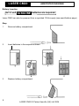
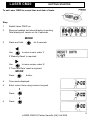
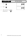
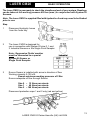
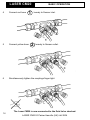
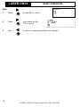
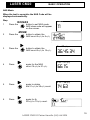
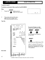
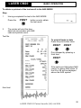
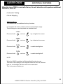
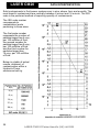
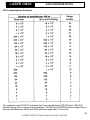
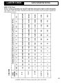
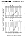
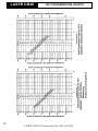
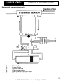
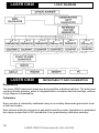
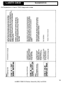
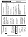
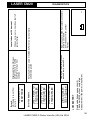
LASER CM20
LASER INFORMATION
This product contains an invisible infra-red 5mW laser.
Any dismantling of the product may result in dangerous exposure to laser radiation.
DANGER – INVISIBLE
LASER RADIATION WHEN
OPEN. AVOID DIRECT
EXPOSURE TO BEAM.
Detail of internal protective housing label, class 3, which is mounted on laser module.
This product is a class 1 laser product which complies with both USA21 CFR 1040.10 &
1040.11 and (BS) EN 608285-1
Please note that users are not required to access the laser radiation and should
never do so.
LASER CM20 © Parker Hannifin (UK) Ltd 2004
CONDITION
MONITORING
LASER CM20
LASER INFORMATION
Introduction
The Parker Laser CM20 Contamination Monitor represents the most upto- date
technology in solid particle contamination analysis, and the first truly portable
monitor.
Laser CM20 is a complex instrument, but at the same time has reliability, simplicity and
ease of operation designed-in.
This owner’s manual has been carefully prepared to guide you, the user, step by step
through how to ‘get started’, how to obtain measurements and how to interpret the results.
Additional information relating to the ‘Aggressive Fluids’ monitor is also included.
The real benefits to be gained from Laser CM20 will be achieved through regular use
particularly as an effective comparator.
With a typical test taking only 2 minutes the opportunities for Laser CM20 as your standard
fluid contamination monitoring instrument are considerable.
Above all, Laser CM20 has been designed to be used.
LASER CM20
CONTENTS
Contents
LASER CM20 FEATURES
LASER CM20 BENEFITS
ANNOTATED DIAGRAMS
GETTING STARTED
BASIC OPERATION
ADDITIONAL FEATURES
DATA INTERPRETATION
COMPONENT CLEANLINESS GUIDELINES
ISO CONTAMINATION CHARTS
HYDRAULIC CIRCUIT DIAGRAM
LOGIC DIAGRAM
DIAGNOSTICS
REAR PANEL
SPECIFICATIONS
ORDERING INFORMATION
OPERATION CHECK LIST
'AGGRESSIVE FLUIDS'
2
LASER CM20 © Parker Hannifin (UK) Ltd 2004
Page
3.
4.
5.
9.
13.
24.
25.
30.
31.
34.
35.
36.
39.
40.
42.
43.
44.
LASER CM20
6 CHANNEL
Features
Test Time: 2 minutes.
Repeat Test Time: Every 2 minutes.
Principle of Operation: Optical scanning analysis and measurement of actual
particulates.
Particle counts: 4+,6+, 14+, 21+, 38+ and 70+ microns(c).
International codes: ISO 7-22 NAS 0-12
Certification: This product complies with all relevant EC declarations of
conformity.
Memory store: 300 test (scrolling memory) capacity.
Calibration: By accepted on-line methods confirmed by the relevant
International Standard Organisation procedures.
Re-calibration: Consult Parker.
Max. working pressure: 420 bar.
Max. flow rate: 400 l/min when used with System 20 Sensors. Higher with
Single Point Sampler (Consult Parker).
Working Conditions: Laser CM20 will operate with the system working normally.
Printer facility: Integral 16 column printer for hard copy data.
Computer compatability: Interface via RS 232 connection @ 9600 baud rate.
Portability: Only 8 kg. Laser CM20 has its own battery pack.
Power requirement: Battery powered or via a 12vDC input (not supplied).
System connection: Via System 20 Inline Sensors or the Single Point Sampler.
Leak free sampling: System 20 sensors ensure sealed fluid extraction and no
contamination ingress.
FAIL SAFE FEATURES
Special ‘Diagnostics’ are incorporated into the Laser CM20 micro processor control to
ensure effective testing.
Circuitry: Incorporates an internal diagnostic programme to ensure
integrity of results.
Adequate flow: Flow test facility ensures adequate flow.
DATA MANAGEMENT
A specially designed DATUM software package is available to enable downloading of test
results onto a computer.
3
LASER CM20 © Parker Hannifin (UK) Ltd 2004
LASER CM20
6 CHANNEL
Benefits
•
Routine contamination monitoring of oil systems with Laser CM20 saves time and
saves money.
•
Contamination monitoring is now possible while machinery is working – Laser CM20
saves on production downtime.
•
Instant, accurate results are available to international standards in hard copy form.
That means system maintenance decisions can be taken immediately.
•
Laser CM20 ensures that machinery hydraulic systems are tested in manufacture to
ISO cleanliness standards.
•
Internal diagnostic feature ensures Laser CM20 will work accurately and reliably.
•
Computer interfacing available for downloading data on to compatible computer.
•
Totally portable, can be used as easily in the field as in the laboratory.
•
Manufactured from lightweight Lexan foam which is both durable and strong.
•
User friendly instrument improves familiarity and awareness of service and maintenance
personnel.
4
LASER CM20 © Parker Hannifin (UK) Ltd 2004
LASER CM20
ANNOTATED DIAGRAM
Monitor – Front View
5
LASER CM20 © Parker Hannifin (UK) Ltd 2004
LASER CM20
ANNOTATED DIAGRAM
Monitor – Rear View
6
LASER CM20 © Parker Hannifin (UK) Ltd 2004
LASER CM20
ANNOTATED DIAGRAM
Hand-held Readout
Alpha Numeric
Display
Micron Sizes
Count
Display Status
Operator
Valve
Low Battery
Paper Feed
Bleep
Charge
Mode
Standard Select
Alpha Numeric
Keys
Print Result
Set Display
7
LASER CM20 © Parker Hannifin (UK) Ltd 2004
LASER CM20
ANNOTATED DIAGRAM
Battery Insertion
6x1.5 volt ALKALINE batteries are required.
Laser CM20 can also be powered from a regulated 12Vdc supply (see specifications page)
Step
1
Remove battery compartment
2
Insert batteries in the sequence shown
3
Replace battery compartment
8
LASER CM20 © Parker Hannifin (UK) Ltd 2004
LASER CM20
GETTING STARTED
To set Laser CM20 to record time and date of tests.
Step
1
Switch Laser CM20 on.
2
Remove handset and check display is working
Total display will remain on for 4 seconds.
MODE
3
Press and hold
Use
for 5 seconds.
to move cursor under Y
if ‘Memory Reset’ is required.
Use
to move cursor under N
if ‘Time and Date’ reset is required.
MODE
Press
button.
4
Time mode displayed.
5
Enter correct time using numeric key pad.
1
Press.
8
6
Press.
9
LASER CM20 © Parker Hannifin (UK) Ltd 2004
LASER CM20
GETTING STARTED
3
7
Press.
8
Press.
9
When correct time is
0
MODE
displayed press.
10
LASER CM20 © Parker Hannifin (UK) Ltd 2004
LASER CM20
GETTING STARTED
To set date.
Step
MODE
1
Having confirmed time by pressing
you are ready to set date.
2
Enter correct date using numeric keypad
1
Press.
5
3
Press.
0
4
Press.
4
5
Press.
9
6
Press.
1
7
Press.
MODE
8
When correct date is displayed press.
11
LASER CM20 © Parker Hannifin (UK) Ltd 2004
LASER CM20
GETTING STARTED
Installing paper and ribbon into the printer.
Step
1
Remove cover and reel axle.
2
Place ribbon cassette in printer
(follow numbered sequence)
3
Feed paper under printer roller.
4
Press paper feed button on
hand held unit.
5
Place paper in paperwell.
6
Feed paper through cover
and secure cover.
12
LASER CM20 © Parker Hannifin (UK) Ltd 2004
LASER CM20
BASIC OPERATION
The Laser CM20 is now ready to check the cleanliness level of your system. Readings
can be taken at full working pressure 420 bar (max.) In conjunction with System 20
Sensors.
Note: The Laser CM20 is supplied filled with hydraulic oil and may need to be flushed
prior to use.
Step
1
Disconnect hydraulic hoses
from the ‘hose tidy’.
2
The Laser CM20 is designed for
use in connection with System 20 size 0, 1 and
2 Industrial Sensors or the Single Point Sampler.
Note: ‘Aggressive Fluids’ monitor
must be connected to a special
System 20 Sensor or
Single Point Sampler.
3
Ensure Sensor is installed with arrow in direction of flow
Working viscosity 2-100 cSt.
Ensure minimum working pressure of 2 Bar
Ensure adequate oil flow through Sensor
Size 0 – 12 litres per minute
Size 1 – 40 litres per minute
Size 2 – 160 litres per minute
Disconnect protection caps 1 and 2 only (red and yellow)
13
LASER CM20 © Parker Hannifin (UK) Ltd 2004
LASER CM20
1
BASIC OPERATION
4
Connect red hose
5
Connect yellow hose
6
Simultaneously tighten the couplings finger tight.
2
loosely to Sensor inlet.
loosely to Sensor outlet.
The Laser CM20 is now connected to the fluid to be checked.
14
LASER CM20 © Parker Hannifin (UK) Ltd 2004
LASER CM20
BASIC OPERATION
We recommend Laser CM20 is connected to operating system sensor for 5 minutes
to allow fluid condition to stabilise before commencing test.
It is also recommended that an independent flow check be carried out if there is
high viscosity oil and low flow through System 20 sensor, or the unit is being
operated without the trace heating option in cold ambient temperatures.
Independent Flow Test
1
Switch Laser CM20 on.
2
Press
3
Flow test will
commence, the display
will show.
4
After 30 seconds the printer will
print out the results of the flowtest.
5
A ∆T (Temp) of ≤03.60°C or less
is required for a successful test
to be achieved.
6
for 5 seconds.
LASER
CM FLOW
TEST
If the ∆T value is >03.60°C then the
flow rate through the System 20
Sensor should be increased or
the system oil temperature raised.
15
LASER CM20 © Parker Hannifin (UK) Ltd 2004
LASER CM20
BASIC OPERATION
Step
1
Select ISO or NAS standard.
This determines the format of
test data stored. ISO/NAS
2
Observe position of operation control valve system
3
Turn valve 90° in indicated
direction. Valve position can be
checked from the top
of the Monitor....
or
.... or from the front of the Monitor.
Important:
Only turn the valve
when starting a test
and only when
the valve turn
symbol
or
is shown on
the display.
Testing will commence immediately
The test will take approximately 2
minutes. The duration bar will run
across the screen for the duration
of the test in 12 segments.
During each test, the appropriate
test number will appear on the
display. Example indicates test
number 001 in progress.
16
LASER CM20 © Parker Hannifin (UK) Ltd 2004
LASER CM20
BASIC OPERATION
ISO Mode
2µ
Step
1
2
When the test is complete,
the ISO Code will automatically
be displayed.
22:20:14
Particle count
To obtain a count for the 4µ (c) particles
press the
MODE
button.
All particle counts are representative
of 100 ml samples.
(C)
3
A count for 4µ(C) will be displayed.
>6µ(C)
4
Press
for the 6µ(C) count.
92:35:19
>14µ(C)
5
Press
again to obtain the 14µ(C) count.
10:00: 1
>21µ(C)
6
Press
again to obtain the 21µ(C) count.
45: 1:
17
LASER CM20 © Parker Hannifin (UK) Ltd 2004
LASER CM20
Step
BASIC OPERATION
>38µ(C)
11: :
7
Press
for the 38µ(C) count.
8
Press
once more for the
70µ(C) count.
9
Use
to return to previous particle count screen.
(C)
18
LASER CM20 © Parker Hannifin (UK) Ltd 2004
LASER CM20
BASIC OPERATION
NAS Mode
When the test is complete the NAS Code will be
displayed automatically.
Step
ISO/NAS
1
Press the
button to set NAS mode.
NAS class code will appear
on the screen.
2
Press the
button to obtain the
NAS count 4µ(C) to 6µ(C).
3
Press the
button to obtain the
NAS count 6µ(C) to 14µ(C).
4
Press
again for the NAS
count 14µ(C) to 21µ(C).
5
Press
again to obtain
the 21µ(C) to 38µ(C) count.
6
Press
again for th
38µ(C) to 70µ(C) count.
>50µ
11: :
MODE
(C)
6µ -14µ(C)
36:45:34
14µ - 21µ(C)
66:15:
21µ - 38µ(C)
14:63:
(C)
19
LASER CM20 © Parker Hannifin (UK) Ltd 2004
LASER CM20
BASIC OPERATION
Step
7
Press
once more for
the 70µ(C) count.
Press
to return to previous particle count screen.
(C)
20
LASER CM20 © Parker Hannifin (UK) Ltd 2004
LASER CM20
BASIC OPERATION
To print a result
To obtain a printout of the result in the ISO MODE
Step
PRINT
1
Press the
button once to
obtain the last result.
2
The printer will print the time,
date and test number with
ISO code and particle count.
Test No
UCC LASER CM
ON-LINE TEST
To print all tests to date
Press the print button twice
PRINT
(C)
>4µ(C)
>6µ(C)
>14µ(C)
>21µ(C)
>38µ(C)
>70µ(C)
PRINT
Print stopped by pressing
a third time
PRINT
If the test count falls below ISO
code 7 or above ISO code 23
then 00 or 99 respectively will be
displayed under the 4µ, 6µ and
14µ symbols.
Next test
21
LASER CM20 © Parker Hannifin (UK) Ltd 2004
LASER CM20
BASIC OPERATION
To obtain a printout of the test result in the NAS MODE
Step
1
Having completed the test in the NAS MODE.
Press the
2
PRINT
button once to obtain
the last result.
The printer will print the time,
date and test number with NAS
code and particle count.
Test No
UCC LASER CM
ON-LINE TEST
To print all tests to date
Press the print button twice
PRINT
PRINT
Print stopped by pressing a
third time
PRINT
4/6µ(C)
6/14µ(C)
14µ/21µ(C)
21µ/38µ(C)
If the test count falls below NAS
class 0 or above NAS class 12
the 00 or 99 will be displayed
above the NAS symbol.
38µ/70µ(C)
>70µ(C)
Next test
22
LASER CM20 © Parker Hannifin (UK) Ltd 2004
LASER CM20
BASIC OPERATION
Calibration Requirement
When switching the unit on, it will check the date as stored in the real-time clock against
the date stored as the last calibration date.
If the date is within 4 weeks of the calibration due date, then the unit shall proceed as
follows:
(this assumes a last calibration date of 29th June 2000)
To continue with testing press
MODE
If the unit passes the recommended calibration due date, then the unit shall proceed as
follows:
MODE
To continue with testing press
23
LASER CM20 © Parker Hannifin (UK) Ltd 2004
LASER CM20
ADDITIONAL FEATURES
When the Laser CM20 is used with Dat∝m, this will allow the unit to perform additional
functions, such as:
• Automatic Testing
• Route Mapping
Additional Keys
The handset has two additional hot key functions
It is supplied with factory default contrast and backlight setings.
These settings are user adjustable as detailed below.
5 MNO
Press and hold
and use
key to lighten the screen.
and use
key to darken the screen.
and use
to switch backlight on.
and use
to switch backlight off.
5 MNO
Press and hold
7 STU
Press and hold
7 STU
Press and hold
NOTE:
When the CM20 is switched off the backlight function is reset.
s required
eq ed when
e thee CM20
C 0 iss switched
Therefore if the backlight iss still
then need
need to
to be
be reactivated.
reactivated.
back on, the backlight wilil then
This is to preserve battery life.
24
LASER CM20 © Parker Hannifin (UK) Ltd 2004
LASER CM20
DATA INTERPRETATION
Solid contaminants in fluid power systems vary in size, shape, form and quantity. The
most harmful contaminants are normally between 6 micron and 14 micron. The ISO
code is the preferred method of reporting quantity of contaminants.
The ISO code number
corresponds to
contamiation levels
pertaining to three sizes.
The first scale number
represents the number of
particles larger than 4µm(C)
per 100 millilitre of fluid,
the second number for
particles larger than 6µm(C)
per 100 milllilitre of fluid
and the third number for
particles larger than
14µm(C) per 100 millilitre
of fluid.
Below is a table of actual
results, obtained, of
contamination within a
Hydraulic Pump
endurance test rig.
m(C)
4 (C)
6 (C)
14 (C)
21 (C)
38 (C)
4
6
14
'
25
LASER CM20 © Parker Hannifin (UK) Ltd 2004
LASER CM20
DATA INTERPRETATION
ISO Contamination Numbers
For example code 20/18/13 indicates that there are between 500,000 and 1,000,000
particles larger than 4 microns and between 130,000 and 250,000 particles larger than 6
microns and between 4000 and 8000 particles larger than 14 microns.
26
LASER CM20 © Parker Hannifin (UK) Ltd 2004
LASER CM20
DATA INTERPRETATION
Particle Distribution Chart to ISO4406: 1999
Including various ISO level contamination grades
6
14
21
(C)
27
LASER CM20 © Parker Hannifin (UK) Ltd 2004
38
LASER CM20
DATA INTERPRETATION
NAS 1638 Chart
over 70
38-70
21-38
14-21
6-14
(C)
NAS 1638
NOTE: in order to implement the new MTD calibration with minimal impact on NAS cleanliness
classes, the reference particle size ranges in NAS 1638 have been revised to relate to the particle
size ranges in ISO 4406:1999. Therefore the NAS class cumulative counts have been aligned with
ISO cumulative counts.
28
LASER CM20 © Parker Hannifin (UK) Ltd 2004
LASER CM20
DATA INTERPRETATION
ISO/NAS/SAE Comparison Chart
BS 5540/4
ISO/DIS
4406:1999 CODE
The above comparisons relate to particle count data only. To conform to any particular
standard, reference should be made to the recommended experimental procedure.
29
LASER CM20 © Parker Hannifin (UK) Ltd 2004
11
13
14
15
17
15
16
18
19
21
LASER CM20 © Parker Hannifin (UK) Ltd 2004
Important
Very Important
Critical
16,000 Average
8,000
4,000
1,000
Low pressure heavy industrial systems,
or applications where long life is not
critical.
General machinery & mobile systems.
Medium pressure, medium capacity.
High quality reliable systems. General
machine requirements.
High performance servo and high
pressure long life systems, i.e. aircraft,
machine tools, etc.
Silt sensitive control system with very
high reliability. Laboratory or aerospace.
TYPE OF SYSTEM
Gear pumps,
manual and poppet
valves cylinders
Vane pumps,
spool valves
Piston pumps,
proportional valves
compensated flow
controls
Industrial
servovalves
High performance
servovalves
TYPICAL
COMPONENTS
1,000,000 64,000 Main protection Low pressure systems with large clearances. Ram pumps
250,000
130,000
32,000
16,000
250
Super critIcal
9
13
4,000
6µm(C)
14µm(C)
6µm(C)
14µm(C)
SUGGESTED
MAXIMUM
SENSITIVITY
PARTICLE LEVEL
TARGET
CONTAMINATION
CLASS TO
ISO 4406:1999
Suggested acceptable contamination levels for various hydraulic systems.
LASER CM20
COMPONENT CLEANLINESS GUIDELINES
30
6
14
31
LASER CM20 © Parker Hannifin (UK) Ltd 2004
(C)
21
38
6
14
(C)
21
These typical applications and ISO code numbers are taken from the UK Contamination
and Control Research Programme (1980-1984).
Ref. AHEM Guide to Contamination Control in Hydraulic Power Systems – 1985
38
LASER CM20
ISO CONTAMINATION CHARTS
Typical system applications and code numbers
ISO CONTAMINATION CHARTS
21
21
6
14
(C)
38
6
14
(C)
38
LASER CM20
32
LASER CM20 © Parker Hannifin (UK) Ltd 2004
ISO CONTAMINATION CHARTS
21
6
14
(C)
38
LASER CM20
21
14
6
33
LASER CM20 © Parker Hannifin (UK) Ltd 2004
(C)
38
Graphs
here
LASER CM20
HYDRAULIC CIRCUIT DIAGRAM
Diagramatic representation only
1.
2.
3.
4.
5.
6.
Monitor Block
Laser Diode
Optical Scanner
Changeover Valve
Dual Direction Syringe Pump
Flow Probe Device
34
LASER CM20 © Parker Hannifin (UK) Ltd 2004
LASER CM20
4 (C)
6 (C)
LASER CM20
LOGIC DIAGRAM
14 (C)
21 (C)
38 (C)
70 (C)
REPEATABILITY AND CALIBRATION
Repeatability
The Laser CM20 Instrument measures and quantifies individual particles. The sizing and
counting of these particles, which is integrated within a complex electrical package, ensures
a high degree of repeatability.
Calibration
Every monitor is individually calibrated using an accurately determined gravimetric level
of test dust media.
Each channel within the instrument is adjusted to read the number of particles in a prescribed
size range as specified in ISO procedures, thus guaranteeing calibration accuracy.
35
LASER CM20 © Parker Hannifin (UK) Ltd 2004
LASER CM20
DIAGNOSTICS
Return to Parker for repair.
An Explanation of Laser CM20 diagnostic codes.
36
LASER CM20 © Parker Hannifin (UK) Ltd 2004
b. DP too high due to lack of
control of flow through Laser CM20.
diag 5a test
time to short
diag 5b test
time to long
b. Air lock in monitor block
or high viscocity slug of
oil in bypass hoses.
37
LASER CM20 © Parker Hannifin (UK) Ltd 2004
Use SPS or sensor to control flow through
Laser CM20
Care should be taken to allow oil discharge
safely and should only be performed by a
competent operator.
Re-test and if fault repeats, return monitor to
Parker for repair.
iii) Use Single Point sampler connected to P1
(see Parker catalogue for details).
Purge the system pressure with P2 hose
disconnected from system.
ii) Reduce viscocity of system oil by increasing
test temperature where possible.
i) Select smaller sized sensor
Leave unit to re-set itself.
d. Power supply connected
(12V DC) while unit is on.
a. Inadequate differential
pressure across P1 and P2
connections to cause
sufficient bypass flow.
Relocate monitor on a sound surface (May
also be hung from a carrying strap).
Replace batteries with 6 x 1.5V Alkaline D Cells
(or re-chargepack if rechargeable pack is fitted.)
Wait for monitor to reset itself.
c. Battery contact
disconnected by excessive
vibration.
b. Battery power too low.
Battery level warning ignored.
a. Uncontrolled power down
by removing power supply
without switching monitor off.
a. Malfunction of Opto-Tacho
control, causing flow to stop
before particle counting phase
completed. Results are suspect
and are not made available.
Pump drive slipping or failed.
Error 5.
test time too short or
too long.
diag 4 low flow
in bypass line
Error 4.
insufficient flow rate of
oil from P1 hose into monitor
block to fill syringe pump.
Results are suspect and are
not made available.
diag 3 power
interruption
Error 3.
a. Power to monitor has been
disrupted
LASER CM20
DIAGNOSTICS
LASER CM20 © Parker Hannifin (UK) Ltd 2004
if it does not re-set, i.e. it switches itself off
contact Parker .
Leave it alone until it has re-set
Displayed if monitor block has
reached temp. above 600c
ISO
Remove Laser CM20 from system connectors.
Allow to cool down.
If unit does not re-set, contact
Parker.
All faults which can only be rectified by Parker and are normally
software diagnostic
Displayed after switching on,
while monitor is re-setting
itself from previous error
condition.
Replace batteries see section (4)
The Laser CM20 will not complete a
measurement if the power is insufficient.
LOW BATTERY
diag 10 laser
temp too high
diag 9 refer to
cm20 supplier
diag 8 refer to
cm20 supplier
diag 7 refer to
cm20 supplier
Error 7 and above.
diag 6 lcm in
reset mode
Error 6.
Unit trying to re-set from
last error.
LASER CM20
DIAGNOSTICS
+
38
LASER CM20
REAR PANEL
Peripherals and Serial interface.
Back Panel
9 way connector to RS 232 output
to down load all test data, stored in
the instrument.
39
LASER CM20 © Parker Hannifin (UK) Ltd 2004
LASER CM20
SPECIFICATIONS
Construction: Case-Lexan structural foam
and ABS. Hand-held display – ABS. Key
pad flurosilicone rubber.
Mechanical Components: Brass, plated
steel, stainless steel and aluminium.
Size, Measurement and Ranges: 4+, 6+,
14+, 21+, 38+ and 70+ micron (c).
Analysis Range: ISO 7 to 22 inclusive.
(NAS 0-12 inclusive).
Calibration: Each unit is individually tested
and calibrated in accordance with ISO
procedures.
Seals: Viton.
Hoses: Nylon (Kevlar braided microbore).
Repeatability/Accuracy: Better than 5%
(typical).
Hose length: Fluid connection hose 1.2
metres (1 metre extensions can be used).
Hand-held display cable length 1.0 metres.
Viscosity Range: 2-100 centistokes (500cSt
with SPS).
Flow Rate: Up to 400 l/min (System 20
Sensors). Higher with Single Point Sampler
– Consult Parker.
Max. Operating Temp: +5°C to +80°C.
Max. Working Pressure: Up to 420 bar
(System 20 Sensors).
Test Completion Time: 2 minutes.
Fluid Compatability: Mineral oil and
petroleum based fluids. For other fluids
consult Parker.
Environmental Temp: +5°C to +40°C.
Computer Interface: RS232 @ 9600 baud
rate.
Laser CM20 Weight: 8 kg.
Power: Battery 6x1.5D cells Transformer
supply voltage 9-12Vdc. Current 1.5 amp.
Jack plug connection positive centre.
(Plug not supplied)
Fuse: 1.25 amp fast blow fuse included for
overload protection.
LCM20 Technology: Unique optical
scanning system.
40
LASER CM20 © Parker Hannifin (UK) Ltd 2004
LASER CM20
SPECIFICATIONS
Installation Details
41
LASER CM20 © Parker Hannifin (UK) Ltd 2004
LASER CM20
ORDERING INFORMATION
LCM20.2021/2023
LCM 6 Channel (including carrying case and kit). ACFTD Calibrated
LCM20.2022/2024
LCM 6 Channel MTD Calibrated
System 20-Sensors
42
LASER CM20 © Parker Hannifin (UK) Ltd 2004
LASER CM20
OPERATION CHECK LIST
Always ensure:
• Sensors are installed correctly
• Sensor connectors are correctly tightened
• Adequate oil flow
• Steady state pressure conditions
• Oil viscosity is within working range
• Trend monitoring is performed under similar working conditions
• Correctly stowed hoses to avoid fluid spillage
• Sufficient paper supplies for hard copy printer
• Handle Laser CM20 with care – Instrumentation product
• Re-order spares in advance
• Calibrated within Parker recommendations
43
LASER CM20 © Parker Hannifin (UK) Ltd 2004
LASER CM20
AGGRESSIVE FLUIDS MONITOR
To expand further the applications possible with Parker’s Laser CM20 particle counting
technology, we are now able to offer a version of Laser CM20 utilising ISOLAST dual
seal technology.
Calibrated in accordance with ISO procedures, on a specially commissioned Skydrol
calibration rig. The LCM20.2062 offers the user all the features and benefits of the already
proven and world-wide accepted Laser CM20 technology.
By using LCM20.2062, civil aviation hydraulic servicing operations can now parallel the
cost and time saving already demonstrated in the military aviation industries.
*Ref.; Parker Technical Update UC.TU.9303.
THIS PRODUCT IS COMPATIBLE WITH
BOTH MINERAL AND AGGRESSIVE FLUIDS.
AVOID CROSS CONTAMINATION BY
FLUSHING THIS MONITOR.
IF IN DOUBT CONTACT PARKER.
NOTE:
Some oils may be classified as Phosphate Esters, but may not be aggressive.
If in doubt with fluid/seal compatibility, consult Parker
44
LASER CM20 © Parker Hannifin (UK) Ltd 2004
LASER CM20
AGGRESSIVE FLUIDS MONITOR
Features:
•
Isolast seals throughout.
•
Totally compatible for Aggressive Phosphate Esters (e.g. SKYDROL LD4/500B)
•
Red control valve knob and hand set keys for easy identification against standard Laser
CM20 units
•
High Technology, fused optical windows for high particle definition
•
Available with complete range of sample extraction options (e.g. System 20 Sensors
or Single Point Sampler)
•
5/8” BSF HSP Hose fitting
•
Parylene treated for additional protection
45
LASER CM20 © Parker Hannifin (UK) Ltd 2004
LASER CM20
Part No.
AGGRESSIVE FLUIDS MONITOR
Qty.
Description
LCM20.2061/2063
Laser CM20 ‘Aggressive Fluids’ ACFTD Calibrated
LCM20.2062/2064
Laser CM20 ‘Aggressive Fluids’ MTD Calibrated
System 20-Sensors
Industrial Sensors – sizes 0, 1 and 2
46
LASER CM20 © Parker Hannifin (UK) Ltd 2004


![IL 2.003.01 [Delta MK2]e-pag1.ai](http://vs1.manualzilla.com/store/data/005753338_1-488e124ad81f3853ba4b74f093f13849-150x150.png)