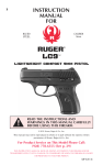
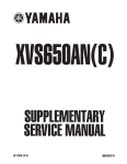
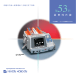
1
FOREWORD This Supplementary Service Manual has been prepared to introduce new service and data for the YZF-R1 2000. For complete service information procedures it is necessary to use this Supplementary Service Manual together with the following manual. YZF-R1 SERVICE MANUAL: 4XV1-AE1 YZF-R1 2000 SUPPLEMENTARY SERVICE MANUAL 1999 by Yamaha Motor Co., Ltd. First Edition, December 1999 Any reproduction or unauthorized use without the written permission of Yamaha Motor Co., Ltd. is expressly prohibited. EB001000 NOTICE This manual was produced by the Yamaha Motor Company, Ltd. primarily for use by Yamaha dealers and their qualified mechanics. it is not possible to include all the knowledge of a mechanic in one manual. Therefore, anyone who uses this book to perform maintenance and repairs on Yamaha vehicles should have a basic understanding of mechanics and the techniques to repair these types of vehicles. Repair and maintenance work attempted by anyone without this knowledge is likely to render the vehicle unsafe and unfit for use. Yamaha Motor Company, Ltd. is continually striving to improve all of its models. Modifications and significant changes in specifications or procedures will be forwarded to all authorized Yamaha dealers and will appear in future editions of this manual where applicable. NOTE: Designs and specifications are subject to change without notice. EB002000 IMPORTANT MANUAL INFORMATION Particularly important information is distinguished in this manual by the following. The Safety Alert Symbol means ATTENTION! BECOME ALERT! YOUR SAFETY IS INVOLVED! WARNING CAUTION: NOTE: Failure to follow WARNING instructions could result in severe injury or death to the motorcycle operator, a bystander or a person checking or repairing the motorcycle. A CAUTION indicates special precautions that must be taken to avoid damage to the motorcycle. A NOTE provides key information to make procedures easier or clearer. EB003000 HOW TO USE THIS MANUAL This manual is intended as a handy, easy-to-read reference book for the mechanic. Comprehensive explanations of all installation, removal, disassembly, assembly, repair and check procedures are laid out with the individual steps in sequential order. 1 The manual is divided into chapters. An abbreviation and symbol in the upper right corner of each page indicate the current chapter. Refer to “SYMBOLS”. 2 Each chapter is divided into sections. The current section title is shown at the top of each page, except in Chapter 3 (“PERIODIC CHECKS AND ADJUSTMENTS”), where the sub-section title(-s) appears. 3 Sub-section titles appear in smaller print than the section title. 4 To help identify parts and clarify procedure steps, there are exploded diagrams at the start of each removal and disassembly section. 5 Numbers are given in the order of the jobs in the exploded diagram. A circled number indicates a disassembly step. 6 Symbols indicate parts to be lubricated or replaced. Refer to “SYMBOLS”. 7 A job instruction chart accompanies the exploded diagram, providing the order of jobs, names of parts, notes in jobs, etc. 8 Jobs requiring more information (such as special tools and technical data) are described sequentially. 6 2 1 3 4 5 8 7 EB004000 1 2 GEN INFO SYMBOLS SPEC 3 4 CHK ADJ ENG 5 6 COOL CARB 7 8 CHAS General information Specifications Periodic checks and adjustments Engine Cooling system Carburetor(-s) Chassis Electrical system Troubleshooting Symbols 10 to 17 indicate the following. 10 10 11 12 13 14 15 16 17 TRBL SHTG 11 12 13 14 15 16 17 18 19 20 24 1 2 3 4 5 6 7 8 9 ELEC 9 21 The following symbols are not relevant to every vehicle. Symbols 1 to 9 indicate the subject of each chapter. 22 23 25 Serviceable with engine mounted Filling fluid Lubricant Special tool Tightening torque Wear limit, clearance Engine speed Electrical data Symbols 18 to 23 in the exploded diagrams indicate the types of lubricants and lubrication points. 18 19 20 21 22 23 Engine oil Gear oil Molybdenum disulfide oil Wheel bearing grease Lithium soap base grease Molybdenum disulfide grease Symbols 24 to 25 in the exploded diagrams indicate the following. 24 Apply locking agent (LOCTITE) 25 Replace the part CONTENTS SPECIFICATIONS GENERAL SPECIFICATIONS . . . . . . . . . . . . . . . . . . . . . . . . . . . . . . . . ENGINE SPECIFICATIONS . . . . . . . . . . . . . . . . . . . . . . . . . . . . . . . . . . CHASSIS SPECIFICATIONS . . . . . . . . . . . . . . . . . . . . . . . . . . . . . . . . . ELECTRICAL SPECIFICATIONS . . . . . . . . . . . . . . . . . . . . . . . . . . . . . TIGHTENING TORQUES . . . . . . . . . . . . . . . . . . . . . . . . . . . . . . . . . . . . ENGINE TIGHTENING TORQUES . . . . . . . . . . . . . . . . . . . . . . . . . CHASSIS TIGHTENING TORQUES . . . . . . . . . . . . . . . . . . . . . . . LUBRICATION POINTS AND LUBRICANT TYPES . . . . . . . . . . . . . ENGINE LUBRICATION POINTS AND LUBRICANT TYPES . . OIL FLOW DIAGRAMS . . . . . . . . . . . . . . . . . . . . . . . . . . . . . . . . . . . . . . COOLANT FLOW DIAGRAMS . . . . . . . . . . . . . . . . . . . . . . . . . . . . . . . CABLE ROUTING . . . . . . . . . . . . . . . . . . . . . . . . . . . . . . . . . . . . . . . . . . 1 2 6 9 11 11 12 13 13 14 17 20 PERIODIC CHECKS AND ADJUSTMENTS INTRODUCTION . . . . . . . . . . . . . . . . . . . . . . . . . . . . . . . . . . . . . . . . . . . PERIODIC MAINTENANCE AND LUBRICATION INTERVALS . . . COWLINGS . . . . . . . . . . . . . . . . . . . . . . . . . . . . . . . . . . . . . . . . . . . . . . . . AIR FILTER CASE AND IGNITION COIL PLATE . . . . . . . . . . . . . . . 33 33 35 36 OVERHAULING THE ENGINE AIR INDUCTION SYSTEM . . . . . . . . . . . . . . . . . . . . . . . . . . . . . . . . . . . ENGINE . . . . . . . . . . . . . . . . . . . . . . . . . . . . . . . . . . . . . . . . . . . . . . . . . . . INSTALLING THE ENGINE . . . . . . . . . . . . . . . . . . . . . . . . . . . . . . . CYLINDER HEAD . . . . . . . . . . . . . . . . . . . . . . . . . . . . . . . . . . . . . . . . . . CRANKCASE . . . . . . . . . . . . . . . . . . . . . . . . . . . . . . . . . . . . . . . . . . . . . . ASSEMBLING THE CRANKCASE . . . . . . . . . . . . . . . . . . . . . . . . . 37 38 39 40 41 43 COOLING SYSTEM RADIATOR . . . . . . . . . . . . . . . . . . . . . . . . . . . . . . . . . . . . . . . . . . . . . . . . 45 CARBURETORS AIR INDUCTION SYSTEM . . . . . . . . . . . . . . . . . . . . . . . . . . . . . . . . . . . AIR INJECTION . . . . . . . . . . . . . . . . . . . . . . . . . . . . . . . . . . . . . . . . . AIR CUTOFF VALVE . . . . . . . . . . . . . . . . . . . . . . . . . . . . . . . . . . . . . AIR INDUCTION SYSTEM DIAGRAMS . . . . . . . . . . . . . . . . . . . . . CHECKING THE AIR INDUCTION SYSTEM . . . . . . . . . . . . . . . . 47 47 47 48 49 CHASSIS FRONT WHEEL AND BRAKE DISCS . . . . . . . . . . . . . . . . . . . . . . . . . INSTALLING THE FRONT WHEEL . . . . . . . . . . . . . . . . . . . . . . . . FRONT AND REAR BRAKES . . . . . . . . . . . . . . . . . . . . . . . . . . . . . . . . REAR BRAKE MASTER CYLINDER AND BRAKE FLUID RESERVOIR . . . . . . . . . . . . . . . . . . . . . . . . . . . . . . . . . . 50 51 52 52 ELECTRICAL INSTRUMENT FUNCTIONS . . . . . . . . . . . . . . . . . . . . . . . . . . . . . . . . . INDICATOR LIGHTS . . . . . . . . . . . . . . . . . . . . . . . . . . . . . . . . . . . . . COOLANT TEMPERATURE WARNING LIGHT . . . . . . . . . . . . . . SPEEDOMETER UNIT . . . . . . . . . . . . . . . . . . . . . . . . . . . . . . . . . . . ELECTRIC STARTING SYSTEM . . . . . . . . . . . . . . . . . . . . . . . . . . . . . STARTER MOTOR . . . . . . . . . . . . . . . . . . . . . . . . . . . . . . . . . . . . . . COOLING SYSTEM . . . . . . . . . . . . . . . . . . . . . . . . . . . . . . . . . . . . . . . . . CIRCUIT DIAGRAM . . . . . . . . . . . . . . . . . . . . . . . . . . . . . . . . . . . . . . TROUBLESHOOTING . . . . . . . . . . . . . . . . . . . . . . . . . . . . . . . . . . . SELF-DIAGNOSIS . . . . . . . . . . . . . . . . . . . . . . . . . . . . . . . . . . . . . . . . . . TROUBLESHOOTING . . . . . . . . . . . . . . . . . . . . . . . . . . . . . . . . . . . YZF-R1 WIRING DIAGRAM (For EUR) YZF-R1 WIRING DIAGRAM (For OCE) 53 53 54 55 57 57 62 62 63 66 67 GENERAL SPECIFICATIONS SPEC SPECIFICATIONS GENERAL SPECIFICATIONS Item Dimensions Overall length Overall width Overall height Seat height Wheelbase Minimum ground clearance Minimum turning radius Weight Wet (with oil and a full fuel tank) Dry (without oil and fuel) Maximum load (total of cargo, rider, passenger, and accessories) Standard Limit 2,035 mm 2,095 mm (for AUS) 695 mm 1,105 mm 815 mm 1,395 mm 140 mm 3,400 mm 194 kg 175 kg 201 kg –1– ENGINE SPECIFICATIONS SPEC ENGINE SPECIFICATIONS Item Engine Engine type Displacement Cylinder arrangement Bore stroke Compression ratio Engine idling speed Vacuum pressure at engine idling speed Standard compression pressure (at sea level) Fuel Recommended fuel Fuel tank capacity Total (including reserve) Reserve only Engine oil Lubrication system Recommended oil Standard Limit Liquid-cooled, 4-stroke, DOHC 998 cm3 Forward-inclined parallel 4-cylinder 74 58 mm 11.8 : 1 1,000 1,100 r/min 29.3 kPa (220 mm Hg) 1,450 kPa (14.5 kgf/cm2) at 400 r/min Regular unleaded gasoline Unleaded fuel (for AUS) 18 L 3.8 L Wet sump Temp. SAE20W40SE or SAE10W30SE Quantity Total amount Without oil filter cartridge replacement With oil filter cartridge replacement Oil pressure (hot) Relief valve opening pressure 3.6 L 2.7 L 2.9 L 45 kPa at 1,100 r/min (0.45 kgf/cm2 at 1,100 r/min) 490 570 kPa (4.9 5.7 kgf/cm2) –2– ENGINE SPECIFICATIONS Item Camshafts Drive system Camshaft cap inside diameter Camshaft journal diameter Camshaft-journal-to-camshaftcap clearance Intake camshaft lobe dimensions SPEC Standard Limit Chain drive (right) 24.500 24.521 mm 24.459 24.472 mm 0.028 0.062 mm Measurement A Measurement B Measurement C Exhaust camshaft lobe dimensions 32.5 32.6 mm 24.95 25.05 mm 7.45 7.65 mm 32.4 mm 24.85 mm Measurement A Measurement B Measurement C Max. camshaft runout 32.95 33.05 mm 24.95 25.05 mm 7.75 7.95 mm 32.85 mm 24.85 mm 0.03 mm –3– ENGINE SPECIFICATIONS Item Standard Valves, valve seats, valve guides Valve clearance (cold) Intake Exhaust Valve dimensions Head Diameter SPEC 0.11 0.20 mm 0.21 0.25 mm Face Width Valve head diameter A Intake Exhaust Valve face width B Intake Exhaust Valve seat width C Intake Exhaust Valve margin thickness D Intake Exhaust Valve stem diameter Intake Exhaust Valve guide inside diameter Intake Exhaust Valve-stem-to-valve-guide clearance Intake Exhaust Valve stem runout Valve seat width Intake Exhaust Connecting rods Crankshaft-pin-to-big-end-bearing clearance Bearing color code Limit Seat Width Margin Thickness 22.9 23.1 mm 24.4 24.6 mm 1.76 2.90 mm 1.76 2.90 mm 0.9 1.1 mm 0.9 1.1 mm 0.5 0.9 mm 0.5 0.9 mm 3.975 3.990 mm 4.465 4.480 mm 3.945 mm 4.43 mm 4.000 4.012 mm 4.500 4.512 mm 4.05 mm 4.55 mm 0.010 0.037 mm 0.020 0.047 mm 0.08 mm 0.1 mm 0.01 mm 0.9 1.1 mm 0.9 1.1 mm 0.031 0.055 mm –1 = Violet 0 = White 1 = Blue 2 = Black –4– ENGINE SPECIFICATIONS Item Transmission Transmission type Primary reduction system Primary reduction ratio Secondary reduction system Secondary reduction ratio Operation Gear ratios 1st gear 2nd gear 3rd gear 4nd gear 5th gear 6th gear Max. main axle runout Max. drive axle runout Carburetors Model (manufacturer) quantity Throttle cable free play (at the flange of the throttle grip) ID mark Main jet Main air jet Jet needle Needle jet Pilot air jet Pilot outlet Pilot jet Bypass 1 Bypass 2 Bypass 3 Pilot screw turns out Valve seat size SPEC Standard Limit Constant mesh, 6-speed Spur gear 68/43 (1.581) Chain drive 43/16 (2.688) Left-foot operation 35/14 (2.500) 35/19 (1.842) 30/20 (1.500) 28/21 (1.333) 30/25 (1.200) 29/26 (1.115) 0.08 mm 0.08 mm BDSR40 (MIKUNI) 4 3 5 mm 5JJ1 00 #130 Carburetors 1 and 4: #60 Carburetors 2 and 3: #65 6DEY5-53-3 P-OM #120 1.0 #15 0.8 0.9 0.8 3.125 1.5 –5– CHASSIS SPECIFICATIONS SPEC CHASSIS SPECIFICATIONS Item Front tire Tire type Size Model (manufacturer) Tire pressure (cold) 0 90 kg 90 197 kg High-speed riding Min. tire tread depth Rear tire Tire type Size Model (manufacturer) Tire pressure (cold) 0 90 kg 90 197 kg High-speed riding Min. tire tread depth Rear brake Brake type Operation Brake pedal position (from the top of the brake pedal to the bottom of the rider footrest bracket) Recommended fluid Brake discs Diameter thickness Min. thickness Max. deflection Brake pad lining thickness Master cylinder inside diameter Caliper cylinder inside diameter Standard Limit Tubeless 120/70 ZR17 (58W) MEZ3Y FRONT (METZELER) D207FQ (DUNLOP) 250 kPa (2.5 kg/cm2, 2.5 bar) 250 kPa (2.5 kg/cm2, 2.5 bar) 250 kPa (2.5 kg/cm2, 2.5 bar) 1.6 mm Tubeless 190/50 ZR17 (73W) MEZ3Y (METZELER)/D207N (DUNLOP) 250 kPa (2.5 kg/cm2, 2.5 bar) 290 kPa (2.9 kg/cm2, 2.9 bar) 250 kPa (2.5 kg/cm2, 2.5 bar) 1.6 mm Single-disc brake Right-foot operation 35 40 mm DOT 4 245 5 mm 5.5 mm 4.5 mm 0.1 mm 0.5 mm 12.7 mm 38.2 mm –6– CHASSIS SPECIFICATIONS Item Front suspension Suspension type Front fork type Front fork travel Spring Free length Spacer length Installed length Spring rate (K1) Spring stroke (K1) Optional spring available Fork oil Recommended oil Quantity (each front fork leg) Level (from the top of the inner tube, with the inner tube fully compressed, and without the fork spring) Damper adjusting rod locknut distance Spring preload adjusting positions Minimum Standard Maximum Rebound damping adjusting positions Minimum* Standard* Maximum* Compression damping adjusting positions Minimum* Standard* Maximum* *with the adjusting screw fully turned in position SPEC Standard Limit Telescopic fork Coil spring/oil damper 135 mm 255 mm 85 mm 242.4 mm 7.35 N/mm (0.75 kgf/mm) 0 135 mm No Suspension oil “01” or equivalent 482 cm3 74 mm 11 mm 8 6 1 11 5 1 9 5 1 –7– CHASSIS SPECIFICATIONS Item Rear suspension Suspension type Rear shock absorber assembly type Rear shock absorber assembly travel Spring Free length Installed length Spring rate (K1) Spring stroke (K1) Optional spring available Standard spring preload gas/air pressure Spring preload adjusting positions Minimum Standard Maximum Rebound damping adjusting positions Minimum* Standard* Maximum* Compression damping adjusting positions Minimum* Standard* Maximum* *with the adjusting screw fully turned in position SPEC Standard Limit Swingarm (link suspension) Coil spring/gas-oil damper 65 mm 176 mm 162.5 mm 78.4 N/mm (7.84 kgf/mm) 0 65 mm No 1,200 kPa (12 kgf/cm2) 1 4 9 11 7 1 11 9 1 –8– ELECTRICAL SPECIFICATIONS SPEC ELECTRICAL SPECIFICATIONS Item Standard Limit System voltage 12 V SSS Ignition system Ignition system type Ignition timing Advanced timing Advancer type Pickup coil resistance/color Transistorized coil ignition unit model (manufacturer) Transistorized coil ignition 5_ BTDC at 1,050 r/min 55_ BTDC at 5,000 r/min Throttle position sensor and electrical 248 372 W/Gy-B TNDF54 (DENSO) SSS SSS SSS SSS SSS SSS Voltage regulator Regulator type Model No-load regulated voltage Semiconductor short circuit SH650A-12 14.1 14.9 V SSS SSS SSS Bulbs (voltage/wattage quantity) Headlight Auxiliary light Tail/brake light Turn signal light Meter light 12 V 60 W/55 W 2 12 V 5 W 2 12 V 5 W/21 W 2 12 V 21 W 4 LED SSS SSS SSS SSS SSS Constant mesh SSS 5JJ (YAMAHA) 0.75 kW SSS SSS 9.8 mm 4.88 7.32 N (488 732 gf) 0.009 0.011 Ω 24.5 mm 1.5 mm 3.65 mm SSS SSS 23.5 mm SSS Full-transistor FE246BH (DENSO) No 75 95 cycles/min. 21 W 2 SSS SSS SSS SSS SSS Oil level switch model (manufacturer) 4XV (DENSO) SSS Fuel pump relay model (manufacturer) G8R-30Y-M (OMRON) SSS Electric starting system System type Starter motor Model (manufacturer) Power output Brushes Overall length Spring force Commutator resistance Commutator diameter Mica undercut Turn signal relay Relay type Model (manufacturer) Self-cancelling device built-in Turn signal blinking frequency Wattage –9– ELECTRICAL SPECIFICATIONS Item Thermo unit Model (manufacturer) Fuses (amperage quantity) Main fuse Headlight fuse Signaling system fuse Ignition fuse Radiator fan fuse Backup fuse (odometer) Reserve fuse SPEC Standard Limit 5JJ (NIPPON THERMOSTAT) 30 A 1 20 A 1 20 A 1 15 A 1 10 A 1 10 A 1 30 A 1 20 A 1 15 A 1 10 A 1 –10– TIGHTENING TORQUES SPEC TIGHTENING TORQUES ENGINE TIGHTENING TORQUES Item Cylinder head Cylinder head Generator rotor Oil/water pump assembly driven sprocket cover Air induction system hose Crankcase Crankcase Crankcase Crankcase Ignitor unit Thread size Q’ty y Nut Cap nut Bolt Bolt M10 M10 M10 M6 Clamp Bolt Bolt Bolt Bolt Screw M7 M9 M6 M6 M8 M5 Fastener NOTE: After tightening to 15 Nm (1.5 mSkg), tighten another 45_ 50_ –11– Tightening torque Nm mSkgf 8 2 1 1 50 65 65 12 5.0 6.5 6.5 1.2 4 10 2 14 2 2 4 0.4 See NOTE 14 1.4 12 1.2 24 2.4 7 0.7 Remarks TIGHTENING TORQUES SPEC CHASSIS TIGHTENING TORQUES Item Thread size Lower ring nut Engine mounting Front mounting bolts Rear upper mounting bolt Rear under mounting bolts Pinch bolts Exhaust pipe bracket Rear master cylinder Tightening Nm mkgf M30 9 0.9 M10 M10 M10 M8 M8 M8 40 55 55 24 24 18 4.0 5.5 5.5 2.4 2.4 1.8 Remarks See NOTE. NOTE: 1. First, tighten the ring nut to approximately 18 Nm (1.8 mkg) with a torque wrench, then loosen the ring nut completely. 2. Retighten the ring nut to specification. –12– LUBRICATION POINTS AND LUBRICANT TYPES SPEC E202000 LUBRICATION POINTS AND LUBRICANT TYPES ENGINE LUBRICATION POINTS AND LUBRICANT TYPES Lubricant Lubrication point Connecting rod bolts and nuts –13– OIL FLOW DIAGRAMS EB203000 OIL FLOW DIAGRAMS 1 2 3 4 5 6 7 Intake camshaft Exhaust camshaft Crankshaft Oil cooler Oil pipe Oil strainer Oil pump –14– SPEC OIL FLOW DIAGRAMS 1 Exhaust camshaft 2 Intake camshaft 3 Oil filter –15– SPEC OIL FLOW DIAGRAMS 1 Cylinder head 2 Crankshaft –16– SPEC COOLANT FLOW DIAGRAMS EB203000 COOLANT FLOW DIAGRAMS 1 2 3 4 5 6 Thermostat Radiator cap Coolant reservoir Radiator Oil cooler Water jacket joint –17– SPEC COOLANT FLOW DIAGRAMS 1 2 3 4 Thermostat housing Water pump Radiator Radiator fan –18– SPEC COOLANT FLOW DIAGRAMS 1 Radiator 2 Thermo unit –19– SPEC CABLE ROUTING SPEC EB206000 CABLE ROUTING 1 2 3 4 5 Clutch cable Left handlebar switch lead Starter cable Main switch lead Steering cover A Properly insert the meter assembly coupler and rubber boot into the meter assembly. B Route the meter assembly lead through the left side of the headlight housing. C The speedometer lead with not be tighten. D Install the headlight relays onto the headlight housing bridge. E Connect to the right front turn signal connectors. F Route the turn signal leads upper the headlight housing boss. –20– CABLE ROUTING G Fasten the headlight lead with a plastic clamp at white tape mark. H Fasten the wire harness to the headlight housing boss with a plastic locking tie. I Route the headlight lead through the plastic guide. J Route the throttle cable to the front side of the brake hose. K Route the clutch cable behind the front fork leg. L Make sure that the horn leads face out. M Route the throttle cables and right handlebar switch lead between the lower bracket and steering cover. SPEC N Route the thermo switch / temperature sender subwire harness to the outside of the radiator cap. O Route the right handlebar switch lead behind the throttle cables. Do not cross the throttle cables and the right handlebar switch lead. P Route the right handlebar switch lead in front of the throttle cables. –21– CABLE ROUTING Rollover valve (California only) Charcoal canister (California only) Rear brake switch lead Timing chain tensioner. Thermostat assembly breather hose Radiator inlet hose Coolant reservoir breather hose Clutch cable Pickup coil lead A Fasten the starter motor lead to the flame which is just before the side cover stay (0 5 mm) with a plastic clamp. B 0 5 mm 1 2 3 4 5 6 7 8 9 SPEC C Route the rollover-valve-to-fuel-tank hose to the inside of the fuel hose (California only). D Route the coolant reservoir breather hose over the timing chain tensioner. E Insert the plastic clip through the hole in the plastic frame panel and then fasten the wire harness and coolant reservoir breather hose with it. F Route the clutch cable between the radiator bracket and frame and in front of the thermostat assembly breather hose. G Route the clutch cable to the inside of the radiator inlet hose. H Insert the plastic clamp into the hole in the coolant reservoir’s tab. –22– CABLE ROUTING 1 Starter cable 2 Air induction system vacuum 3 4 5 6 7 8 9 10 11 hose Air induction system hose Sidestand switch lead Oil level switch lead Clamp Right handlebar switch lead Throttle cables Air guide Air filter case breather hose Coolant reservoir breather hose SPEC Fuel tank overflow hose and fuel tank breather hose Drive chain sprocket cover Coolant hose EXUP servomotor A Route the air filter case breather hose and air induction system hose to the inside of the wire harness. B Through the air cleaner drain hose, coolant reservoir tank breather, fuel tank breather hose, fuel tank over flow hose, air induction system hose and air induction system vacuum hose outside of the AC magneto lead. Then, clamp all of them at just behind of the air induction system protector and air induction system vacuum hose protector, moreover at under the three sides pipe. 12 13 14 15 –23– CABLE ROUTING C D E F SPEC To the connector cover. J Route the sidestand switch lead and oil level switch Route the seat lock cable over the wire harness. lead to the inside of the drive sprocket cover. Fasten the wire harness with a plastic clamp. K Do not crush the water pump breather hose and Make sure the rear flasher light lead coupler and plastic clip. tail light lead coupler in the rubber cover. L Pass the fuel tank breather hose and the air filter G Route the rear turn signal lead through the hole in the drain hose through the steel clamps and then after upper rear fender. routing the hoses to the exterior of the under cowlH 50 mm ing, align the leading ends of the hoses. I Fasten the sidestand switch lead, engine oil level M Route the engine oil level switch lead and sideswitch lead, and water pump breather hose with a stand switch lead inside the coolant hose. plastic clip. –24– CABLE ROUTING N Pass the fuel tank breather hose and the air filter Q drain hose through the inside of the coolant hose. R No hose must be inserted into the under cowling. S O Pass the air filter drain hose and the coolant reservoir hose through the inside of the coolant hose and route the leading ends to the bottom of the T coolant hose. The leading ends must not protrude from the under cowling. U P Fasten the air filter drain hose, coolant hose, cool- V ant reservoir tank breather hose, fuel tank breather hose, fuel tank drain hose and air induction system W hose at the steel clamp. SPEC To the air filter. To the fuel tank. Insert the fuel tank breather hose into a back side nipple of fuel tank. The fuel tank nipple and the fuel tank breather hose have each white mark. Insert the fuel tank over flow hose into a front side nipple of fuel tank. To the air vent surge tank. Adjust the all clip’s direction to back side of the body. Clamp under a three sides pipe. –25– CABLE ROUTING Speed sensor lead Charcoal canister (California only) EXUP cables EXUP A Route the EXUP cables behind the cross tube. B Route the neutral switch lead direct to upper right side. C Route the EXUP cables on the outside of the engine mount. 1 2 3 4 SPEC D Route the EXUP cables behind the swing arm head pipe. E Fasten the EXUP cables and engine mount with a plastic locking tie. –26– CABLE ROUTING 1 2 3 4 5 6 7 8 9 10 11 12 Headlight sub-wire harness Left handlebar switch lead Main switch lead Starter cable Right handlebar switch coupler Throttle cables Engine air vent hose EXUP servomotor coupler Air vent surge tank Starter motor lead Pickup coil coupler Fuel pump coupler 13 14 15 16 17 18 19 20 21 22 23 24 SPEC Neutral switch connector Battery negative lead Rear brake switch coupler Speed sensor coupler EXUP cable Fuel tank overflow hose Fuel tank breather hose (except for California) Tail light lead Rear flasher light lead Crankcase breather hose Generator coupler Sidestand switch coupler –27– CABLE ROUTING 25 26 27 28 29 30 31 32 33 34 35 Engine oil level switch lead Air filter case drain hose Air induction system hose Ignition coil Cover Rivet Screw Coupler Main harness Frame Rear fender –28– SPEC CABLE ROUTING A Make sure the headlight lead in the rubber cover. B Route the horn lead over the horn bracket and make sure that the lead has no slack. C Do not cross the throttle cables and right handlebar switch lead. D Route the thermo switch lead through the steel band on the radiator. E Fasten the main harness and thermo switch lead with a plastic clamp. Insert the plastic clamp into the hole on the frame. F Route the ignition coil sub-wire harness under the throttle position sensor. SPEC G To the carburetor. H Route the coolant reservoir tank breather hose upper the air vent surge tank. I Fasten the wire harness and ignition coil subwire harness with a plastic clamp. J Route the idle adjust cable upper the ground lead. K Fasten the fuel pump lead, speed sensor lead, neutral switch lead, rear brake light lead, fuel sender lead, starter motor lead and EXUP cable with a plastic clamp. –29– CABLE ROUTING SPEC L Fasten the fuel pump lead, speed sensor lead, tank breather hose have each white mark. neutral switch lead, rear brake light lead, fuel send- S 30 mm (1.17 in) er lead, starter motor lead and EXUP cable with a T Fasten the battery positive lead and starter motor plastic clamp. lead with a plastic locking tie. M 125 mm (4.88 in) U Route the rear flasher light lead in the hole on the N 50 mm (1.95 in) rear fender. O To the fuel cock. V Insert the tail / brake light lead and turn signal leads P To the fuel sender. under the tail / brake light. Q Insert the fuel tank over flow hose into a front side W Fasten the rear flasher light lead and taillight lead nipple of fuel tank. with a plastic clamp. Route the rear flasher light R Insert the fuel tank breather hose into a back side lead and taillight lead in the hole on the taillight nipple of fuel tank. The fuel tank nipple and the fuel bracket. –30– CABLE ROUTING X Fasten the main harness with a plastic band on the rear fender. Y Position the ground coupler over the main harness. Z Route the ground lead under the starter relay lead. A’ Fasten the starter relay lead, ground lead, starting circuit cutoff relay lead, alam lead and main harness with a plastic clamp. Route the clamp end to outside, and insert it between wire harness and fender. B’ Route the taillight leads through the rear fender. C’ Fasten the main harness, battery negative lead and rear fender with a plastic clamp. Clamp the battery negative lead with a white tape mark. SPEC D’ At the back side of turning point, battery negative lead is fixed to wire harness. E’ Route the fuel tank overflow hose and fuel tank breather hose in front of the crank case breather hose and under the fuel hose and front of the EXUP servomotor bracket and upper the EXUP servomotor. F’ To the idle adjust screw. G’ To the engine backward. H’ Make sure the sidestand switch coupler, engine oil level sensor coupler, EXUP servo motor coupler and acmagneto coupler in the rubber cover. –31– CABLE ROUTING I’ Fasten the main harness with a plastic clamp. Insert the plastic clamp into the hole on the frame. J’ Route the charcoal canister hose under the engine air vent hose, coolant reservoir tank breather hose and all of leads. (California only) K’ Fasten the wire harness with a plastic clamp and then insert the clamp into the frame. L’ To the radiator fan motor. M’ Route the main harness and fan motor lead into the hole on the air intake guide. Fasten the main harness and fan motor lead with a plastic clamp. N’ Route the band end to inside. The clamp position SPEC should be not exceed just behind 30 mm of all coupler. O’ 0 30 mm P’ Although the main switch lead couplers and the handlebar switch lead couplers are the same in shape, they differ in color (the former is white, and the latter, blue). Connect the couplers of the same color. Q’ Direct the ignition coil leads upward and insert them into position at the rubber damper. R’ 90_ S’ Route the battery negative lead inside the main harness. T’ Route the battery positive lead upper the main harness. –32– PERIODIC MAINTENANCE AND LUBRICATION INTERVALS CHK ADJ EB300000 PERIODIC CHECKS AND ADJUSTMENTS INTRODUCTION This chapter includes all information necessary to perform recommended checks and adjustments. If followed, these preventive maintenance procedures will ensure more reliable vehicle operation, a longer service life and reduce the need for costly overhaul work. This information applies to vehicles already in service as well as to new vehicles that are being prepared for sale. All service technicians should be familiar with this entire chapter. EB301000 PERIODIC MAINTENANCE AND LUBRICATION INTERVALS No No. ITEM CHECKS AND MAINTENANCE JOBS 1 * Fuel line Check fuel hoses and vacuum hose for cracks or damage. Replace if necessary. 2 * Fuel filter Check condition. Replace if necessary. 3 4 Spark plugs * Valves After the first 1,000 km Every Every 10,000 km 20,000 km Annual check Check condition. Clean, regap or replace if necessary. Check valve clearance. Adjust if necessary. Every 40,000 km 5 Air filter Clean or replace if necessary. 6 Clutch Check operation. Adjust or replace cable. 7 * Front brake Check operation, fluid level and vehicle for fluid leakage. Correct accordingly. Replace brake pads if necessary. 8 * Rear brake Check operation, fluid level and vehicle for fluid leakage. Correct accordingly. Replace brake pads if necessary. 9 * Brake hose Check for cracks or damage. Replace if necessary. 10 * Wheels Check balance, runout and for damage. Rebalance or replace if necessary. 11 * Tires Check tread depth and for damage. Replace if necessary. Check air pressure. Correct if necessary. Check bearing for looseness or damage. Replace if necessary. 13 * Swingarm Check swingarm pivoting point for play. Correct if necessary. Lubricate with lithium soap base grease. 14 Drive chain Check chain slack. Adjust if necessary. Make sure that the rear wheel is properly aligned. Clean and lubricate. Every 1,000 km and after washing the motorcycle or riding in the rain 15 * Steering bearings Check bearing play and Steering for roughness. Correct accordingly. 12 * Wheel bearings Lubricate with lithium soap base grease. –33– Every 24,000 km PERIODIC MAINTENANCE AND LUBRICATION INTERVALS No No. ITEM CHECKS AND MAINTENANCE JOBS After the first 1,000 km CHK ADJ Every Every 10,000 km 20,000 km Annual check 16 * Chassis fasteners S Make sure that all nuts, bolts and screws are properly tightened. S Tighten if necessary. 17 Sidestand S Check operation. S Lubricate and repair if necessary. 18 * Sidestand switch S Check operation. S Replace if necessary. 19 * Front fork S Check operation and for oil leakage. S Correct accordingly. Rear shock 20 * absorber assembly S Check operation and shock absorber for oil leakage. S Replace shock absorber assembly if necessary. Rear suspension 21 * relay arm and connecting arm pivoting points S Check operation. S Correct if necessary. 22 * Carburetors S Check engine idling speed, synchronization and starter operation. S Adjust if necessary. 23 Engine oil S Check oil level and vehicle for oil leakage. S Correct if necessary. S Change. (Warm engine before draining.) 24 Engine oil filter cartridge S Replace. 25 * Cooling system Cooling system S Check coolant level and vehicle for coolant leakage. S Correct if necessary. Front and rear 26 * brake switches S Change coolant. S Check operation. S Correct accordingly. 27 Moving parts and cables S Lubricate if necessary. 28 * Air induction system S Check the air cut valve and reed valve for damage. S Replace the entire air induction system if necessary. 29 * Exhaust system S Check the screw clamp for looseness. S Tighten if necessary. 30 * Lights, signals and switches S Check operation. S Correct if necessary. S Adjust headlight beam if necessary. * Since these items require special tools, data and technical skills, have a Yamaha dealer perform the service. NOTE: D The annual checks must be performed once a year unless a 10,000 km or 20,000 km maintenance was performed in the same year. D The air filter needs more frequent service if you are riding in unusually wet or dusty areas. D Hydraulic brake service S Regularly check and, if necessary, correct the brake fluid level. S Every two years replace the internal components of the brake master cylinder and caliper, and change the brake fluid. S Replace the brake hoses every four years and if cracked or damaged. –34– COWLINGS CHK ADJ EB302020 COWLINGS 5 Nm (0.5 mkg) Order 1 2 3 4 5 6 7 8 9 Job/Part Removing the cowlings Rider and passenger seats Rear cowling Bottom cowling Front cowling inner panel (left) Front cowling inner panel (right) Left side cowling Right side cowling Windshield Rear view mirror Front cowling Q’ty Remarks Remove the parts in the order listed. Refer to “SEATS”. 1 1 1 1 1 1 1 2 1 Front installation, reverse the removal procedure. –35– AIR FILTER CASE AND IGNITION COIL PLATE CHK ADJ EB302040 AIR FILTER CASE AND IGNITION COIL PLATE Order 1 2 3 4 5 6 7 8 9 10 11 Job/Part Removing the air filter case and ignition coil plate Rider seat and fuel tank Crankcase breather hose Air filter case breather hose Air induction system hose Clamp screw Bolt Air filter case Quick fastener Ignition coil coupler Spark plug cap Ignition coil plate/ignition coil Rubber baffle Q’ty Remarks Remove the parts in the order listed. Refer to “SEATS” and “FUEL TANK”. 1 1 1 4 1 1 2 1 4 1/2 1 Loosen. Disconnect. For installation, reverse the removal procedure. –36– ENGINE CHK ADJ OVERHAULING THE ENGINE AIR INDUCTION SYSTEM 4 Nm (0.4 mkg) Order 1 2 3 4 Job/Part Q’ty Removing the air induction system Air induction pipe Air cutoff valve Carburetor joint hose Air intake hose Remarks Remove the parts in the order listed. 4 1 1 1 For installation, reverse the removal procedure. –37– ENGINE ENG ENGINE 24 Nm (2.4 mkg) 40 Nm (4.4 mkg) 55 Nm (5.5 mkg) 40 Nm (4.0 mkg) 55 Nm (5.5 mkg) Order 24 Nm (2.4 mkg) Job/Part Q’ty Remove the parts in the order listed. NOTE: Place a suitable stand under the frame and engine. Removing the engine 1 2 3 4 5 6 7 8 9 Pinch bolt Right front mounting bolt Washer Spacer Left front mounting bolt Washer Self-locking nut Rear mounting bolt Spacer Remarks 2 1 1 1 2 2 2 2 1 Loosen. For installation, reverse the removal procedure. –38– ENGINE ENG EB400700 INSTALLING THE ENGINE 1. Install: engine assembly a. Install the spacer 1 to the frame. b. Temporally tighten the right front mounting bolt 2 , left front mounting bolt 3 , and washers 4 5 . c. Lubricate the rear mounting bolts 6 7 threads with lithium soap base grease. d. Install the rear mounting bolts 6 7 and self locking nut 8 9 . e. Tighten the self locking nut 8 , and then tighten the self locking nut 9 . f. Tighten the pinch bolt 10 . g. Tighten the left mounting bolt 3 . h. Tighten the right mouthing bolt 2 . i. Tighten the pinch bolt 11 . Self locking nut 8 9 55 Nm (5.5 mkg) Right front mounting bolt 2 40 Nm (4.0 mkg) Left front mounting bolt 3 40 Nm (4.0 mkg) Pinch bolts 10 11 24 Nm (2.4 mkg) –39– CYLINDER HEAD ENG EB402000 CYLINDER HEAD 50 Nm (5.0 mkg) 65 Nm (6.5 mkg) 12 Nm (1.2 mkg) Order 1 2 3 Job/Part Removing the cylinder head Engine Intake and exhaust camshafts Cylinder head Cylinder head gasket Dowel pin Q’ty Remarks Remove the parts in the order listed. Refer to “ENGINE”. Refer to “CAMSHAFTS”. 1 1 2 For installation, reverse the removal procedure. –40– CRANKCASE ENG CRANKCASE 10 Nm (1.0 mkg) 10 Nm (1.0 mkg) Order 1 2 3 4 5 Job/Part Q’ty Separating the crankcase Engine Cylinder head Pickup coil and pickup coil rotor Stator coil assembly Clutch housing and starter clutch idle gear Oil/water pump assembly Timing chain Crankshaft sprocket Pin Oil/water pump assembly drive chain guide Oil/water pump assembly drive chain Remarks Remove the parts in the order listed. Refer to “ENGINE”. Refer to “CYLINDER HEAD”. Refer to “PICKUP COIL”. Refer to “GENERATOR”. Refer to “CLUTCH”. Refer to “OIL PAN AND OIL PUMP”. 1 1 1 1 1 –41– CRANKCASE ENG 10 Nm (1.0 mkg) 10 Nm (1.0 mkg) Order 6 7 8 9 10 Job/Part Oil/water pump assembly drive sprocket Washer Plate Lower crankcase Dowel pin Q’ty Remarks 1 1 1 1 3 For installation, reverse the removal procedure. –42– CRANKCASE ENG EB412743 ASSEMBLING THE CRANKCASE 1. Lubricate: crankshaft journal bearings (with the recommended lubricant) Recommended lubricant Engine oil 2. Apply: sealant (onto the crankcase mating surfaces and the groove a of the oil baffle plate) Yamaha bond No. 1215 90890-85505 NOTE: Do not allow any sealant to come into contact with the oil gallery or crankshaft journal bearings. Do not apply sealant to within 2 X 3 mm of the crankshaft journal bearings. 3. Install: dowel pin 4. Install: crankshaft journal lower bearings (into the lower crankcase) NOTE: Align the projections a on the crankshaft journal lower bearings with the notches b in the lower crankcase. Install each crankshaft journal lower bearing in its original place. 5. Set the shift drum assembly and transmission gears in the neutral position. –43– CRANKCASE ENG 6. Install: S lower crankcase 1 (onto the upper crankcase 2 ) CAUTION: Before tightening the crankcase bolts, make sure that the transmission gears shift correctly when the shift drum assembly is turned by hand. 7. Install: S crankcase bolts NOTE: S Lubricate the bolt threads with engine oil. S Install a washer on bolts 1 X 10 . S Tighten each bolt at 15 Nm in the tightening sequence cast on the crankcase. S Loosen each bolt one time and tighten 15 Nm in the same sequence. S Tighten bolts 1 to 10 45_ X 50_ more. S Tighten bolts 11 to 28 as shown below. M9 M8 M8 M6 M6 M6 M6 M6 M6 M6 115 mm bolts: 1 X 10 60 mm bolt: 21 50 mm bolt: 22 70 mm bolts: 17 , 19 , 25 65 mm bolt: 27 64 mm bolts: 16 , 24 60 mm bolt: 23 55 mm bolts: 11 X 15 50 mm bolt: 18 45 mm bolts: 20 , 26 , 28 Bolt 1 X 10 15 Nm (1.5 mSkg) + 45_ X 50_ Bolt 11 X 15 , 17 X 20 , 23 , 25 X 28 12 Nm (1.2 mSkg) Bolt 16 , 24 14 Nm (1.4 mSkg) Bolt 21 , 22 24 Nm (2.4 mSkg) –44– RADIATOR COOL EB500000 COOLING SYSTEM RADIATOR 10 Nm (1.0 mkg) 20 Nm (2.0 mkg) 9 Nm (0.9 mkg) 23 Nm (2.3 mkg) 4.5 Nm (0.45 mkg) Order Job/Part Q’ty Remove the parts in the order listed. Refer to “SEATS” and “FUEL TANK” in chapter 3. Refer to “AIR FILTER CASE AND IGNITION COIL PLATE” in chapter 3. Refer to “COWLINGS” in chapter 3. Refer to “ENGINE” in chapter 4. Drain. Refer to “CHANGING THE COOLANT” in chapter 3. Removing the radiator Rider seat and fuel tank Air filter case and rubber cover Bottom cowling and side cowlings Drive sprocket cover Coolant 1 2 3 4 Coolant reservoir breather hose Coolant reservoir hose Coolant reservoir Thermo unit coupler Remarks 1 1 1 1 –45– Disconnect. RADIATOR COOL 10 Nm (1.0 mkg) 20 Nm (2.0 mkg) 9 Nm (0.9 mkg) 23 Nm (2.3 mkg) 4.5 Nm (0.45 mkg) Order 5 6 7 8 9 10 11 12 13 14 15 Job/Part Thermo unit Thermostat assembly breather hose Radiator inlet hose Oil cooler outlet hose Water pump breather hose Radiator outlet hose Water pump inlet pipe Radiator fan motor coupler Horn bracket Radiator Radiator fan Q’ty 1 1 1 1 1 1 1 1 1 1 1 Remarks Disconnect. Disconnect. Disconnect. For installation, reverse the removal procedure. –46– AIR INDUCTION SYSTEM CARB EAS00507 CARBURETORS AIR INDUCTION SYSTEM AIR INJECTION The air induction system burns unburned exhaust gases by injecting fresh air (secondary air) into the exhaust port, reducing the emission of hydrocarbons. When there is negative pressure at the exhaust port, the reed valve opens, allowing secondary air to flow into the exhaust port. The required temperature for burning the unburned exhaust gases is approximately 600 to 700_C. EAS00508 AIR CUTOFF VALVE The air cutoff valve is operated by the intake gas pressure through the piston valve diaphragm. Normally, the air cutoff valve is open to allow fresh air to flow into the exhaust port. During sudden deceleration (the throttle valve suddenly closes), negative pressure is generated and the air cutoff valve is closed in order to prevent after-burning. Additionally, at high engine speeds and when the pressure decreases, the air cutoff valve automatically closes to guard against a loss of performance due to self-EGR. (This “low-boost close” function is the same as on the FZR600 (3HW).) VIEW 1. (NO FLOW) VIEW 1. (NO FLOW) When decelerating (the throttle closes), the valve will close. VIEW 2. (FLOW) During normal operation the valve is open. A From the air filter B To the reed valve C To the carburetor joint VIEW 2. (FLOW) –47– AIR INDUCTION SYSTEM EAS00509 AIR INDUCTION SYSTEM DIAGRAMS 1 2 3 4 Reed valve Air cleaner Air cutoff valve Carburetor joint (cylinder #1) A B D D E –48– To the air cutoff valve To cylinder #1 To cylinder #2 To cylinder #3 To cylinder #4 CARB AIR INDUCTION SYSTEM CARB EAS00510 CHECKING THE AIR INDUCTION SYSTEM 1. Check: hoses Loose connection Connect properly. Cracks/damage Replace. pipes Cracks/damage Replace. 2. Check: fibre reed 1 fibre reed stopper reed valve seat Cracks/damage Replace. 3. Measure: fibre reed bending limit a Out of specification Replace the reed valve. Fibre reed bending limit 0.4 mm 1 Surface plate 4. Check: air cutoff valve Cracks/damage Replace. –49– FRONT WHEEL AND BRAKE DISCS CHAS EB700002 CHASSIS FRONT WHEEL AND BRAKE DISCS 6 Nm (0.6 mkg) 72 Nm (7.2 mkg) 40 Nm (4.0 mkg) 18 Nm (1.8 mkg) Order Job/Part Q’ty Remove the parts in the order listed. NOTE: Place the motorcycle on a suitable stand so that the front wheel is elevated. Removing the front wheel and brake discs 1 2 3 4 5 6 7 8 Brake hose holder (left and right) Brake caliper (left and right) Wheel axle pinch bolt Front wheel axle Front wheel Collar (left and right) Oil seal cover (left and right) Brake disc (left and right) Remarks 2 2 1 1 1 2 2 2 Loosen. Refer to “INSTALLING THE FRONT WHEEL”. For installation, reverse the removal procedure. –50– FRONT WHEEL AND BRAKE DISCS CHAS EB700725 INSTALLING THE FRONT WHEEL 1. Lubricate: wheel axle oil seal lips Recommended lubricant Lithium soap base grease 2. Install: brake discs 1 18 Nm (1.8 mkg) NOTE: Apply LOCTITE 648 to the threads of the brake disc bolts. Tighten the brake disc bolts in stages and in a crisscross pattern. 3. Tighten: wheel axle 1 wheel axle pinch bolt 1 72 Nm (7.2 mkg) 23 Nm (2.3 mkg) NOTE: When front wheel is installed to front fork, make sure that wheel axle 1 top end side and front fork end side are align a together. Then, tighten wheel axle pinch bolt 2 . CAUTION: Before tightening the wheel axle nut, push down hard on the handlebars several times and check if the front fork rebounds smoothly. 4. Install: brake calipers 40 Nm (4.0 mkg) WARNING Make sure that the brake hose is routed properly. –51– FRONT AND REAR BRAKES CHAS EB702202 FRONT AND REAR BRAKES REAR BRAKE MASTER CYLINDER AND BRAKE FLUID RESERVOIR 5 Nm (0.5 mkg) 30 Nm (3.0 mkg) 23 Nm (2.3 mkg) Order Job/Part Q’ty 1 2 3 4 5 6 7 8 9 10 Removing the rear brake master cylinder and brake fluid reservoir Brake fluid Brake fluid reservoir cap Brake fluid reservoir diaphragm holder Brake fluid reservoir diaphragm Brake fluid reservoir Brake fluid reservoir hose Hose joint Union bolt Copper washer Brake hose Brake master cylinder Remarks Remove the parts in the order listed. Drain. 1 1 1 1 1 1 1 2 1 1 For installation, reverse the removal procedure. –52– INSTRUMENT FUNCTIONS ELEC ELECTRICAL INSTRUMENT FUNCTIONS INDICATOR LIGHTS Neutral indicator light “ ” This indicator light comes on when the transmission is in the neutral position. ” High beam indicator light “ This indicator comes on when the headlight high beam is used. Turn signal indicator light “ ” This indicator light flashes when the turn signal switch is pushed to the left or right. 1 2 3 4 5 Neutral indicator light “ ” High beam indicator light “ ” Turn signal indicator light “ ” Fuel level warning light “ ” Oil level warning light “ ” Fuel level warning light “ ” This warning light comes on when the fuel level drops below approximately 3.8 L. When this occurs, refuel as soon as possible. The electrical circuit of the warning light can be checked according to the following procedure. 1. Set the engine stop switch to “ ” and turn the key to “ON”. 2. Shift the transmission into the neutral position or pull the clutch lever. 3. Push the start switch. If the warning light does not come on while pushing the start switch, have a Yamaha dealer check the electrical circuit. NOTE: This model is equipped with a selfdiagnosis device for the fuel level warning light circuit. Refer to “SELF-DIAGNOSIS”. Oil level warning light “ ” This warning light comes on when the engine oil level is low. The electrical circuit of the warning light can be checked according to the following procedure. 1. Set the engine stop switch to “ ” and turn the key to “ON”. 2. Shift the transmission into the neutral position or pull the clutch lever. 3. Push the start switch. If the warning light does not come on while pushing the start switch, have a Yamaha dealer check the electrical circuit. NOTE: Even if the oil level is sufficient, the warning light may flicker when riding on a slope or during sudden acceleration or deceleration, but this is not a malfunction. –53– INSTRUMENT FUNCTIONS ELEC COOLANT TEMPERATURE WARNING LIGHT 1 Coolant temperature gauge 2 Coolant temperature warning light “ Coolant temperature warning light “ ” This warning light comes on when the engine overheats. When this occurs, stop the engine immediately and allow the engine to cool. The electrical circuit of the warning light can be checked according to the following procedure. 1. Set the engine stop switch to “ ” and turn the key to “ON”. 2. Shift the transmission into the neutral position or pull the clutch lever. 3. Push the start switch. If the warning light does not come on while pushing the start switch, have a Yamaha dealer check the electrical circuit. ” CAUTION: Do not operate the engine if it is overheated. Coolant temperature Display Conditions What to do Message “LO” is displayed. OK. Go ahead with riding. Temperature is displayed. OK. Go ahead with riding. 117 – 139_C Temperature flashes. Warning light comes on. Stop the motorcycle and allow it to idle until the coolant temperature goes down. If the temperature does not go down, stop the engine. Refer to “OVER HEATING” in chapter 9. Above 140_C Message “HI” flashes. Warning light comes on. Stop the engine and allow it to cool. Refer to “OVER HEATING” in chapter 9. 0 – 39_C 40 – 116_C –54– INSTRUMENT FUNCTIONS ELEC SPEEDOMETER UNIT The speedometer unit is equipped with the following: a digital speedometer (which shows riding speed) an odometer (which shows the total distance traveled) two tripmeters (which show the distance traveled since they were last set to zero) a fuel reserve tripmeter (which shows the distance traveled on the fuel reserve) a clock 1 Speedometer 2 Odometer / tripmeter / fuel reserve tripmeter / clock 3 “RESET” button 4 “SELECT” button Odometer and tripmeter modes Pushing the “SELECT” button switches the display between the odometer mode “ODO” and the tripmeter modes “TRIP 1” and “TRIP 2” in the following order: ODO TRIP 1 TRIP 2 ODO If the fuel level warning light comes on (see page 3-2), the odometer display will automatically change to the fuel reserve tripmeter mode “TRIP F” and start counting the distance traveled from that point. In that case, pushing the “SELECT” button switches the display between the various tripmeter and odometer modes in the following order: TRIP F TRIP 1 TRIP 2 ODO TRIP F To reset a tripmeter, select it by pushing the “SELECT” button, and then push the “RESET” button. If you do not reset the fuel reserve tripmeter manually, it will reset itself automatically and the display will return to “TRIP 1” after refueling and traveling 5 km. NOTE: After resetting the fuel reserve tripmeter, the display will return to “TRIP 1”, unless a different mode had been previously selected; in that case, the display automatically returns to the prior mode. –55– INSTRUMENT FUNCTIONS ELEC Clock mode To change the display to the clock mode, push the “SELECT” button for at least one second. To change the display back to the odometer modes, push the “SELECT” button. To set the clock: 1. Push the “SELECT” button and “RESET” button together for at least two seconds. 2. When the hour digits start flashing, push the “RESET” button to set the hours. 3. Push the “SELECT” button, and the minute digits will start flashing. 4. Push the “RESET” button to set the minutes. 5. Push the “SELECT” button and then release it to start the clock. Tachometer The electric tachometer allows the rider to monitor the engine speed and keep it within the ideal power range. CAUTION: Do not operate the engine in the tachometer red zone. Red zone: 11,750 r/min and above Self-diagnosis devices This model is equipped with a self-diagnosis device for the following electrical circuits: Throttle position sensor Speed sensor EXUP system If any of those circuits are defective, the tachometer will repeatedly display the following error code: 0 r / min for 3 seconds –56– Circuit-specific number of r / min for 2.5 seconds (See the table below.) Current engine speed for 3 seconds ELECTRIC STARTING SYSTEM ELEC ELECTRIC STARTING SYSTEM STARTER MOTOR 5 Nm (0.5 mkg) 7 Nm (0.7 mkg) Order 1 2 3 4 Job/Part Removing the starter motor Rider seat Fuel tank Left side cowling EXUP servomotor Throttle stop screw Starter motor lead Starter motor assembly Q’ty Remarks Remove the parts in the order listed. Refer to “SEATS” in chapter 3. Refer to “FUEL TANK” in chapter 3. Refer to “COWLINGS” in chapter 3. 1 1 1 1 For installation, reverse the removal procedure. –57– ELECTRIC STARTING SYSTEM ELEC EB803501 5 Nm (0.5 mkg) Order 1 2 3 4 5 6 7 8 9 Job/Part Disassembling the starter motor Starter motor rear cover Bearing Starter motor yoke O-ring Armature assembly Brush Brush holder Starter motor front cover Bearing Q’ty Remarks Disassembly the parts in the order listed. 1 1 1 2 1 2 1 1 1 For assembly, reverse the disassembly procedure –58– ELECTRIC STARTING SYSTEM ELEC EB803511 Checking The Starter Motor 1. Check: S commutator Dirt Clean with 600 grit sandpaper. 2. Measure: S commutator diameter a Out of specification Replace the starter motor. Min. commutator diameter 23.5 mm 3. Measure: S mica undercut a Out of specification Scrape the mica to the proper measurement with a hacksaw blade which has been grounded to fit the commutator. Mica undercut 1.5 mm NOTE: The mica must be undercut to ensure proper operation of the commutator. 4. Measure: S armature assembly resistances (commutator and insulation) Out of specification Replace the starter motor. a. Measure the armature assembly resistances with the pocket tester. Pocket tester 90890-03112 Armature assembly Commutator resistance 1 Continuity OK NO continuity NG Insulation resistance 2 Above 1 MΩ at 20_C b. If any resistance is out of specification, replace the starter motor. –59– ELECTRIC STARTING SYSTEM ELEC 5. Measure: brush length a Out of specification Replace the brushes as a set. Min. brush length 3.65 mm 6. Measure: brush spring force Out of specification Replace the brush springs as a set. Brush spring force 5.28 X 7.92 N 7. Check: gear teeth Damage/wear Replace the gear. 8. Check: bearing oil seal Damage/wear Replace the defective part(-s). EB803701 Assembling The Starter Motor 1. Install: brush seat 1 NOTE: Align the tab a on the brush seat with the slot b in the starter motor front cover. 2. Install: armature 1 –60– ELECTRIC STARTING SYSTEM ELEC 3. Install: starter motor yoke 2 O-rings 1 New starter motor rear cover 3 bolts 5 Nm (0.5 mkg) NOTE: Align the match marks a on the starter motor yoke with the match marks b on the front and rear covers. –61– COOLING SYSTEM EB807000 COOLING SYSTEM CIRCUIT DIAGRAM 1 5 6 22 28 48 49 50 Main switch Battery Main fuse Thermo unit Combination meter Radiator fan motor Radiator fan motor relay Radiator fan motor fuse –62– ELEC COOLING SYSTEM EB807010 ELEC EB802401 TROUBLESHOOTING 2. Battery S The radiator fan motor fails to turn. S The coolant temperature meter needle fails to move when the engine is warm. S Check the condition of the battery. Refer to “CHECKING AND CHARGING THE BATTERY” in chapter 3. CAUTION: Open-circuit voltage 12.8 V or more at 20_C S If the engine is kept running at over 1,500 rpm for at least one minute with the switch remaining placed in neutral position and the throttle valve fully open, even when the coolant temperature is low enough, the radiator fan motor will start rotating. This, however, is not trouble. S Keep hands and other body regions away to avoid injury. Check: 1. main, signal system, and radiator fan motor fuses 2. battery 3. main switch 4. radiator fan motor 5. Fan motor relay 6. Speedometer 7. Thermo unit 8. Wiring (the entire cooling system) NOTE: S Before troubleshooting, remove the following part(-s). 1) rider seat 2) bottom cowling 3) front cowling inner panels 4) left side cowling 5) windshield S Troubleshooting with the following special tool(-s). S Is the battery OK? YES NO S Clean the battery terminals. S Recharge or replace the battery. EB802411 3. Main switch S Check the main switch for continuity. Refer to “CHECKING THE SWITCHES”. S Is the main switch OK? YES NO Replace switch. the main EB807400 4. Radiator fan motor S Disconnect the radiator fan motor coupler from the wire harness. S Connect the battery (12 V) as shown. Battery positive lead blue 1 Battery negative lead black 2 Pocket tester 90890-03112 EB802400 1. Main, signal system and radiator fan motor fuses S Check the main, signal system, and radiator fan motor fuses for continuity. Refer to “CHECKING THE FUSES” in chapter 3. S Are the main, signal system, and radiator fan motor fuses OK? YES S Does the radiator fan motor turn? YES NO NO The radiator fan motor is faulty and must be replaced. Replace the fuse(-s). –63– COOLING SYSTEM EB807400 ELEC EB807402 5. Fan motor relay 7. Thermo unit S Disconnect the fan motor relay coupler. S Connect the pocket tester (Ω 1) and battery (12V) to the fan motor relay coupler as shown. S Remove the thermo unit from the radiator. S Connect the pocket tester (Ω 1) to the thermo unit 1 as shown. S Immerse the thermo unit in a container filled with coolant 2 . NOTE: Make sure that the thermo unit terminals do not get wet. Battery positive lead brown 1 Battery negative lead green/black 2 Tester positive prove brown 3 Tester negative prove blue 4 S Place a thermometer 3 in the coolant. S Slowly heat the coolant, then let it cool to the specified temperature as indicated in the table. S Check the thermo unit for continuity at the temperatures indicated in the table. Thermo unit 9.7 X 11.4 kΩ at 50_C 3.4 X 4.0 kΩ at 80_C 1.6 X 1.9 kΩ at 105_C 1.1 X 1.2 kΩ at 120_C S Does the radiator fan motor relay have continuity between brown and blue? YES NO Replace the fan motor relay. EB807400 6. Speedometer S Disconnect the thermo unit coupler. S Set the main switch to “ON”. S Connect the green/red 1 and black/blue 2 terminals with a jumper lead 3 as shown. WARNING S Handle the thermo unit with special care. S Never subject the thermo unit to strong shocks. If the thermo unit is dropped, replace it. S Does the coolant temperature display “HI” and warning light comes on? YES NO Thermo unit 23 Nm (2.3 mSkg) Three bond sealock 10 The speedometer is faulty and must be repaired. –64– COOLING SYSTEM Does the thermo unit operate properly as described above? YES NO Replace the thermo unit. EB807403 8. Wiring Check the entire cooling system’s wiring. Refer to “CIRCUIT DIAGRAM”. Is the cooling system’s wiring properly connected and without defects? YES This circuit is OK. NO Properly connect or repair the cooling system’s wiring. –65– ELEC SELF-DIAGNOSIS ELEC EB812000 SELF-DIAGNOSIS The YZF-R1 features a self-diagnosing system for the following circuit(-s): throttle position sensor EXUP speed sensor fuel level warning light If any of these circuits are defective, their respective condition codes will be displayed on the tachometer when the main switch is set to “ON” (irrespective of whether the engine is running or not) Circuit Throttle position sensor Defect(-s) Disconnected Short-circuit Locked EXUP Improper connection Short-circuit Servomotor is locked. Speed sensor Fuel level warning light Disconnected Short-circuit Improper connection Short-circuit System response The ignitor unit stays set to the wide-open throttle ignition timing. The motorcycle can be ridden. The tachometer displays the condition code. The EXUP valve stays in the open position for three seconds and then the servomotor shuts off. The motorcycle can be ridden. The tachometer displays the condition code. The servomotor’s power supply is constantly interrupted so that it will not burn out. The motorcycle can be ridden. The tachometer displays the condition code. The tachometer displays the condition code. Display the condition code on the fuel level warning light. Condition code 3,000 r/min 7,000 r/min 4000 r/min The warning light will flash eight times, then go off for three seconds. Tachometer display sequence Revolution ( 103 r / min) Tachometer display 1 0 r / min ... 3 seconds 2 Condition code ... 2.5 seconds 3 Engine speed ... 3 seconds Engine speed Time (seconds) When more than one item is being monitored, the tachometer needle displays the condition codes in ascending order, cycling through the sequence repeatedly. If the engine is stopped, the engine speed 3 is 0 r/min. –66– SELF-DIAGNOSIS ELEC EB812010 2. Speed sensor TROUBLESHOOTING Place the motorcycle on a suitable stand so that the rear wheel is elecated. Connect the pocket tester (DC 20V) to the speed sensor connector. The tachometer starts to display the selfdiagnosis sequence. Check: 1. speed sensor 2. fuel level warning light NOTE: Troubleshoot tool(-s). with the Tester (+) lead ³ White 1 terminal Tester (–) lead ³ Body earth following special Pocket tester 90890-03112 1. Speed sensor CIRCUIT DIAGRAM Set the main switch to “ON”. Turn the rear wheel slowly. Check the tester voltage (0V - 5V - 0V). Is the speed sensor OK? YES Replace the ignitor unit. NO Replace the speed sensor. 2. Fuel level warning light (Refer to signal system) 16 Ignitor unit 21 Speed sensor 1. Wire harness Check the wire harness for continuity. Refer to “CIRCUIT DIAGRAM”. Is the wire harness OK? YES NO Repair or replace the wire harness. –67– YZF-R1 WIRING DIAGRAM (For EUR) COLOR CODE B ..... Br . . . . Ch . . . Dg . . . G .... Gy . . . L ..... O .... P ..... R..... black brown chocolate dark green green gray blue orange pink red Sb . . . . W .... Y ..... B/ L . . . B/ R . . . B/ W . . B/ Y . . . Br/ L . . Br/ R . . Br/ W . sky blue white yellow black/ blue black/ red black/ white black/ yellow brown/ blue brown/ red brown/ white G/R . . G/W . . G/Y . . L/B . . . L/R . . . L/W . . L/Y . . . O/R . . R/ B . . . R/ G . . green / red green / white green / yellow blue/ black blue/ red blue/ white blue/ yellow orange / red red / black red / green R/ L . . . R/ W . . R/ Y . . . W/ B . . W/ G . . W/ Y . . Y/ B . . . Y/ L . . . red / blue red / white red / yellow white/ black white/ green white/ yellow yellow/ black yellow/ blue 1 2 3 4 5 6 7 8 9 10 11 12 13 14 15 16 17 18 19 20 21 22 23 24 25 26 27 28 29 30 31 32 33 34 35 36 37 38 39 40 41 42 43 44 45 46 47 48 49 50 51 52 53 54 55 56 57 58 59 60 61 Main switch Backup fuse (odometer) Rectifier/ regulator Generator Battery Main fuse Starter relay Starter motor Relay unit Starting circuit cutoff relay Fuel pump relay Fuel pump Sidestand switch EXUP servomotor Throttle position sensor Ignition unit Ignition coil Spark plug Pickup coil Neutral switch Speed sensor Thermo unit Meter assembly Fuel level indicator light Oil level warning light Neutral indicator light Tachometer Combination meter Coolant temperature meter High beam indicator light Turn signal indicator light Meter light Fuel sender Left handlebar switch Pass switch Dimmer switch Horn switch Horn Clutch switch Turn signal switch Turn signal relay Rear turn signal light Front turn signal light Headlight Auxiliary light Headlight relay Tail/ brake light Radiator fan motor Radiator fan motor relay Radiator fan motor fuse Headlight fuse Signaling system fuse CYCLELOCK (option) Ignition fuse Engine oil level switch Rear brake light switch Right handlebar switch Front brake light switch Lights switch Engine stop switch Start switch YZF-R1 WIRING DIAGRAM (For OCE) COLOR CODE B ..... Br . . . . Ch . . . Dg . . . G .... Gy . . . L ..... O .... P ..... R..... black brown chocolate dark green green gray blue orange pink red Sb . . . . W .... Y ..... B/ L . . . B/ R . . . B/ W . . B/ Y . . . Br/ L . . Br/ R . . Br/ W . sky blue white yellow black/ blue black/ red black/ white black/ yellow brown/ blue brown/ red brown/ white G/R . . G/W . . G/Y . . L/B . . . L/R . . . L/W . . L/Y . . . O/R . . R/ B . . . R/ G . . green / red green / white green / yellow blue/ black blue/ red blue/ white blue/ yellow orange / red red / black red / green R/ L . . . R/ W . . R/ Y . . . W/ B . . W/ G . . W/ Y . . Y/ B . . . Y/ L . . . red / blue red / white red / yellow white/ black white/ green white/ yellow yellow/ black yellow/ blue 1 2 3 4 5 6 7 8 9 10 11 12 13 14 15 16 17 18 19 20 21 22 23 24 25 26 27 28 29 30 31 32 33 34 35 36 37 38 39 40 41 42 43 44 45 46 47 48 49 50 51 52 53 54 55 56 57 58 Main switch Backup fuse (odometer) Rectifier/ regulator Generator Battery Main fuse Starter relay Starter motor Relay unit Starting circuit cutoff relay Fuel pump relay Fuel pump Sidestand switch EXUP servomotor Throttle position sensor Ignition unit Ignition coil Spark plug Pickup coil Neutral switch Speed sensor Thermo unit Meter assembly Fuel level indicator light Oil level warning light Neutral indicator light Tachometer Combination meter Coolant temperature meter High beam indicator light Turn signal indicator light Meter light Left handlebar switch Pass switch Dimmer switch Horn switch Horn Clutch switch Turn signal switch Turn signal relay Fuel sender Rear turn signal light Front turn signal light Headlight Headlight relay Tail/ brake light Radiator fan motor Radiator fan motor relay Radiator fan motor fuse Headlight fuse Signaling system fuse Ignition fuse Engine oil level switch Rear brake light switch Right handlebar switch Front brake light switch Engine stop switch Start switch