1
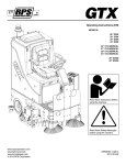
COMMERCIAL CLEANING EQUIPMENT
Operating Instructions (EN)
MODELS:
20'' Disk
26'' Disk
28'' DIisk
24'' Cylindrical
24'' EDGE
28'' EDGE
Read these Instructions before
using the machine.
Read these Safety Messages
before using the machine.
Scan With Phone for more Information
www.tomcatequip.com
1711 South Street
Racine, WI 53404 (USA)
(800) 450-9824 | (+001) 262-681-6470
© 2015 RPS Corporation
VERSION 15.167
RS-OP-EN
INTRODUCTION
This manual is furnished with each new machine. This manual will allow the Operator to get the best performance out of
your RPS manufactured Scrubber-Drier, Sweeper, Burnisher, or Orbital Scrubber. Read this manual thoroughly before
operating or servicing the machine.
This machine will provide excellent performance, but the best results will be obtained at the most minimum costs if:
• The machine is regularly maintained - per the machine Preventative Maintenance instructions provided.
• The machine is operated with reasonable care and caution.
• The machine is maintained with manufacturer supplied parts.
ABOUT THIS MANUAL
TABLE OF CONTENTS: Tells you where to look in the manual.
SAFETY MESSAGES: Section contains important information regarding hazard or unsafe practices of the machine. Levels of hazards are identified that could result in product or personal injury, or severe injury resulting in death.
OPERATION CONTROLS / MACHINE COMPONENTS: Shows you the different machine controls and features.
MACHINE SETUP: Tells you how to setup machine from un-crating to installing squeegee and brushes.
MACHINE OPERATION: Section is to familiarize the operator with the operation and function of the machine.
BATTERY CHARGING: Shows you how to charge the batteries (on-board and off board charging).
MAINTENANCE: This section contains preventative maintenance to keep the machine and it’s components in good working condition. They are listed in this general order:
• Batteries
• Scrub Brushes
• Adjusting Squeegee
• Service Schedule
• Machine Trouble Shooting
TROUBLE SHOOTING: A list of common problems that may occur.
MACHINE SPECS: Tells you Machine Specifications for the various parts of the machine.
MACHINE INSTALL FORM: Should be filled out upon machine installation and faxed to 1-866-632-6961 or online at
www.rpscorporation.com.
WARRANTY POLICY: Tells you coverage, exclusions and limitations to warranty.
NOTE: The serial number of your machine is located on the lower half of the control panel of the machine.
SERIAL NUMBER
AS OUR POLICY IS ONE OF CONSTANT IMPROVEMENT - ALL INFORMATION AND
SPECIFICATIONS ARE SUBJECT TO CHANGE WITHOUT NOTICE.
-2-
RS-OP-EN
TABLE OF CONTENTS
Introduction
2
About This Manual
2
Table of Contents
3
Safety Messages
4
Safety Label Locations
6
Operation Controls
7
Operation Controls
8
Machine Components
9
Battery Charging
External Battery Charging:
On-Board Charger
On-Board Battery Charging (Optional):
Description of LED
Un-Crating Machine:
Connecting Batteries:
Adjusting Squeegee:
Removing Squeegee:
Replacing or Rotating Squeegee Blades:
Installing Disk Pad Driver or Brush:
Installing Driver Pads:
Leveling Disk Decks:
Adjust Disk Shroud Wipers:
Adjust Disk Shrouds:
Installing Cylindrical Brush:
Leveling Cylindrical Decks:
Adjust Cylindrical Wipers Blades:
Installing EDGE Pads:
Leveling EDGE Decks:
Adjust EDGE Shroud Wipers:
Adjust EDGE Shrouds:
Machine Operation
Pre-Cleaning Checklist:
Operating Hints:
One Pass Scrubbing:
Vacuum Only:
Adjust Solution Flow:
Draining Recovery Tank:
Flush Recovery Tank:
Draining Solution Tank:
Solution Filter:
Cleaning Solution Filter:
Squeegee Up:
Squeegee Down:
Clean Vacuum Screen:
Releasing Parking Brake Override Lever:
RS-OP-EN
10
10
10
11
11
11
12
12
13
13
13
14
15
15
16
16
17
17
23
24
24
24
Battery Maintenance Guide
25
Safety:
Inspection and Cleaning:
Storage:
Watering:
25
25
25
25
Maintenance
Machine Setup
23
Daily Maintenance:
Weekly Maintenance:
Monthly maintenance:
Yearly Maintenance:
Storing Machine:
Checking Battery Specific Gravity:
26
26
26
26
26
26
26
RS PM Records
27
RS Wiring Guide
29
Trouble-shooting
30
Machine Specs
32
Common Wear Parts
33
Round Disk Brushes:
Round Disk Pads:
EDGE Pads and Screens:
33
33
33
Soap Choices
35
Standard Warranty Policy
37
Machine Install / Warranty Registration
38
18
18
18
19
19
19
20
20
20
21
21
21
21
22
22
-3-
SAFETY MESSAGES
You will see four kinds of safety reminders in this manual:
DANGER
DANGER indicates a hazardous situation which, if not
avoided, will result in death or serious injury.
WARNING
WARNING indicates a potentially hazardous situation
which, if not avoided, could result in death or serious
injury.
CAUTION
CAUTION indicates a potentially hazardous situation
which, if not avoided, could result in minor or moderate
injury or damage to this machine or nearby objects. CAUTION also can be used to alert against unsafe practices.
NOTICE
NOTICE indicates information considered important, but
not hazard-related. This safety message may be related
to property damage or warranty warnings.
Your safety, and that of others, is very important. Operating this machine safely is an important responsibility.
DO NOT OPERATE THIS MACHINE:
• Unless you are trained and authorized to do so
• Unless you have read and understood this Operator’s Manual
• On surfaces with greater than a 2% grade unless this machine is equipped with a functional parking brake
• On surfaces with greater than an 8% grade at any time
WHEN OPERATING THIS MACHINE:
• Remove loose objects from the floor that could be projected from the rotating Brushes
• Keep your hands and feet away from the rotating Brushes
• Do not operate this machine where flammable liquids are present
• Use caution when maneuvering
BEFORE LEAVING THE MACHINE:
• Park the machine on a level surface
• Turn the machine OFF ( )
BEFORE SERVICING THE MACHINE:
• Disconnect the Batteries
DANGER
Explosive hydrogen gas forms when Batteries are
charging. An open flame or spark can cause this gas
to explode. Serious personal injury or property damage
could occur. Only charge the Batteries in this machine in
a well ventilated area.
-4-
DANGER
Flammable materials can cause an explosion or fire. Do
not use flammable materials in Tank or pick up.
RS-OP-EN
WARNING
The Batteries in this machine produce hazardous
voltage which can cause electrical shock, burns and/
or electrocution. Always disconnect Batteries before
servicing this machine.
WARNING
When climbing or descending ramps, always drive
machine forward. To avoid overturning the machine, Do
not back down ramps. Do not drive across inclines. Do
not turn while ascending or descending ramps. Overturning the machine can cause serious injury or death.
WARNING
Do not use water that exceeds 135°F / 57°C. If water is above said temperature, this will void the Tank
Warranty.
WARNING
Do not park this machine on ramps or slopes. Always
park this machine on a level, hard surface. Do not operate this machine outdoors or on uneven surfaces.
WARNING
The Batteries in this machine contain sulfuric acid,
which causes burns to skin. If battery acid contacts
clothing or skin, rinse the effected area with cold water
immediately. If battery acid gets on your face or in your
eyes, flush the area immediately with cold water and
seek medical attention.
WARNING
To avoid electrical shock, do not operate this machine
over electrical floor outlets.
CAUTION
To avoid damage to this machine, use only cleaning
solutions and replacement parts recommended by the
manufacturer.
CAUTION
Do not operate this machine if any parts have been
damaged or removed.
WARNING
Dress safely. Do not wear rings or metal wrist watches
when servicing this machine, as they can cause an
electrical short circuit which can cause serious burns.
WARNING
Do not remove, paint over or destroy warning decals. If
warning decals become damaged, call 1-262-681-3583
for free replacements.
WARNING
Dress safely. Do not wear a neck tie, scarf, or any
loose or dangling clothing while operating this machine.
Loose or dangling clothing or neck-wear can tangle in
rotating parts, causing serious injury or death.
WARNING
Always turn off this machine before leaving it unattended. Do not allow untrained persons to operate this
machine.
WARNING
NO RIDERS. Do not carry passengers on this machine. Do not use this machine as a stepladder or work
platform.
WARNING
Understand the dynamic braking system before you
operate the machine on ramps. Machine may coast.
WARNING
Before you service a Battery, always wear face protection, protective gloves and protective clothing. Battery
acid or battery explosion can cause serious injuries.
CAUTION
Always use the automatic battery charger provided by
the manufacturer of this machine to charge the Batteries of this machine. It is designed to charge the Batteries at the appropriate rate. If you must use a different
charger, disconnect the Batteries before charging to
avoid damage to the electronic speed controller.
CAUTION
To avoid damage to the electronic control components
of this machine, Do not store this machine outdoors. Do
not pressure wash this machine.
RS-OP-EN
-5-
SAFETY LABEL LOCATIONS
Read and obey all Safety Labels on your RS Floor Scrubber. If you have questions about these labels, ask your supervisor.
These images indicate where on the RS Safety Labels are located. If ever the labels become illegible, worn off, or torn,
promptly report it to your supervisor and replace it.
DANGER
EXPLOSION RISK!
EXPLOSIVE HYDROGEN GAS FORMS WHEN
BATTERIES ARE CHARGING. AN OPEN FLAME
OR SPARK CAN CAUSE THIS GAS TO EXPLODE.
ONLY CHARGE THE BATTERIES IN THIS MACHINE IN A WELL VENTILATED AREA.
DANGER
EXPLOSION RISK!
EXPLOSIVE HYDROGEN GAS FORMS WHEN
BATTERIES ARE CHARGING. AN OPEN FLAME
OR SPARK CAN CAUSE THIS GAS TO EXPLODE.
ONLY CHARGE THE BATTERIES IN THIS MACHINE IN A WELL VENTILATED AREA.
USE ONLY DISTILLED WATER IN THE BATTERIES. USE
ONLY THE OEM CHARGER PROVIDED WITH THE MACHINE. ALWAYS DISCONNECT THE BATTERY BEFORE
SERVICING THE MACHINE.
REFER TO MANUAL OR CALL +011-262-681-3583
USE ONLY DISTILLED WATER IN THE BATTERIES. USE
ONLY THE OEM CHARGER PROVIDED WITH THE MACHINE. ALWAYS DISCONNECT THE BATTERY BEFORE
SERVICING THE MACHINE.
REFER TO MANUAL OR CALL +011-262-681-3583
BATTERY CHARGING LABEL
PART #: 250-7290
DANGER
DAN GER
EXPLOSION RISK!
#!53%!.
&,!--!",%-!4%2)!,3#!. 53%&,!-
%80,/3)/./2&)2%$/./4 0)#+50
-!",%-!4%2)!,3).4!.+/2
TO AVOID DAMAGE TO
THIS MACHINE:
.,9
s53%!002/6%$$%4%2'%.43/4%8#%%$˚F/ 54˚#
s7!4%24%-0%2!452%-534./
%",%!#(-)8452%
s$/./453%()'(0%2#%.4!'
REFER TO MANUAL
OR CALL +011-262-681-3583
EXPLOSION RISK!
&,!--!",%-!4%2)!,3#!.#!53%!.
%80,/3)/./2&)2%$/./453%&,!-
-!",%-!4%2)!,3).4!.+/20)#+50
TO AVOID DAMAGE TO THIS MACHINE:
s53%!002/6%$$%4%2'%.43/.,9
s7!4%24%-0%2!452%-534./4%8#%%$˚F/ 54˚#
s$/./453%()'(0%2#%.4!'%",%!#(-)8452%
REFER TO MANUAL OR CALL +011-262-681-3583
TANK LABEL
PART #: 5-728
-6-
RS-OP-EN
OPERATION CONTROLS
8
1
13
2
14
3
4
15
5
6
10
9
11
12
16
17
7
18
19
1.
BATTERY GAUGE / HOUR METER: Indicates the amount of battery charge remaining along with total hours
used - Below 20% and machine goes into “creep” mode to save charge to allow machine to be driven back to
charging station
2.
BRUSH MOTOR AMP GAUGE: Indicates amp draw of the Scrubdeck motors combined
3.
VACUUM SWITCH [WHITE]: Turns the Vacuum Motor ON (
4.
SOLUTION FLOW SWITCH [BLUE]: Turns solution flow ON (
5.
SCRUBDECK SWITCH [BLACK]: Raises and lowers the Scrubdeck - Scrubdeck turns on automatically when
lowered and foot pedal is pressed
6.
KEY SWITCH: Turns power of the machine ON (
7.
REVERSE SWITCH [RED]: Switch to forward position to drive forward - back position for reverse (Alarm will
sound in reverse)
8.
SOLUTION FLOW CONTROL LEVER: Adjusts the amount of solution flow delivered to the Scrubdeck ( + / - )
9.
CIRCUIT BREAKER: 15 amp Positive Bus Bar ( + )
10.
CIRCUIT BREAKER: 15 amp Negative Bus Bar ( - )
11.
CIRCUIT BREAKER: 25 amp Vacuum Motor
12.
CIRCUIT BREAKER: 30 amp Scrubdeck Motor
13.
CHARGER PORT: Plug in grey charger connector here to charge machine batteries (OEM 36 Volt / 25 Amp Only)
14.
QR CODE: Scan machine serial QR Code and see all of the machines BornOn Information
15.
RECHARGE METER: Indicates amount of times machine has been connected to a charger
16.
POWER ON METER: Hour meter to indicate complete time key has been ON (
17.
DRIVE MOTOR METER (OPTIONAL): Indicates complete time Drive Motor has been in use
18.
SCRUBDECK MOTOR METER (OPTIONAL): Indicates complete time Scrub Motor(s) has been in use
19.
VACUUM MOTOR METER (OPTIONAL): Indicates complete time Vacuum Motor has been in use
RS-OP-EN
) / OFF (
) / OFF (
)/ OFF (
)
)
)
)
-7-
OPERATION CONTROLS
1
2
3
4
5
1.
ADJUSTABLE STEERING: Four settings for operator comfort and ease of entry
2.
HORN: Sounds the horn for warning oncoming traffic
3.
HEADLIGHT SWITCH: Turns power of the Headlight ON (
4.
SQUEEGEE LIFT LEVER: Raises and lowers the Squeegee
5.
EMERGENCY STOP (OPTIONAL): Allows for complete machine shut down with
) / OFF (
)
1-button push
-8-
RS-OP-EN
MACHINE COMPONENTS
1
19
18
2
17
3
20
4
21
5
22
16
29
15
23
6
28
24
14
7
27
25
8
26
13
9
10
6
11
12
1.
DRAIN SAVER / RECOVERY TANK LID: Easy visibility Recovery Tank Lid allows viewing of Drain Saver and Recovery Tank
2.
3.
RECOVERY TANK: 23 Gallon Capacity - Tip back for easy cleaning
4.
5.
6.
7.
8.
9.
10.
11.
12.
SOLUTION FILL POINT: Fill easily with hose
13.
14.
15.
16.
17.
18.
19.
20.
21.
TANK LATCHES: Permits draining of the Recovery Tank as well as access to secondary fill point and components in back of
the machine
SOLUTION TANK: 22 Gallon Capacity
TIE DOWN POINTS: Location for tie down straps during transport (4)
SQUEEGEE BLADE: Squeegees water to be recovered by the vacuum hose
REAR WHEELS: Cut for complete water control
ROLLER BRACKETS: Designed to prevent damage to the deck (Required - Do Not Remove)
LOWER FRAME ROLLER BRACKET: Designed to prevent damage to the front of the machine (Required - Do Not Remove)
FRONT DRIVE TIRE: Drives and steers the machine
LED HEADLIGHTS (OPTIONAL): Helps you see in low light areas and to warn oncoming traffic
PARKING BRAKE: Turns the parking brake ON (
) / OFF (
) - Never leave in the OFF (
) position to drive machine
POLYURETHANE ROLLERS: Helps prevent damage to machine and objects you may drive near (Walls)
METERS: Machine Total Hour Meter & Recharge Counter are standard - Drive, Scrubdeck, and Vacuum are OPTIONAL Meters
CHARGER PORT: Plug in your console charger here (36 Volt / 25 amp ONLY)
STEERING WHEEL: Steers the main Drive Wheel
SEAT: Ergonimic seat with operator comfort in mind
VACUUM FLOAT SHUT-OFF: Automatic Vacuum Shut-off if Recovery Tank is Full
VACUUM HOSE: Main Vacuum Hose from the Squeegee to the Drain Saver
SPRAY JET HOSE (OPTIONAL): Optional Spray Jet hose allows operator to utilize the Solution Tanks cleaning solution in
areas where the machine may not reach to scrub
22. RECOVERY DRAIN HOSE: Allows for controlled draining of the Recovery Tank
23. SOLUTION SIGHT GAUGE & DRAIN HOSE: Shows precise level of cleaning solution in Tank while also used as a Solution
Tank drain hose
24.
25.
26.
27.
28.
29.
REAR BUMPER: Offers squeegee system protection from damage
SQUEEGEE ROLLERS: Helps protect the Squeegee
SQUEEGEE PITCH ADJUSTMENT: Recovers dirty water from the floor to be recovered by Vacuum Hose
SIDE WIPERS: Controls water on turns by directing it to the Squeegee
ADJUSTABLE SCRUBDECK ARMS: Ensure your Scrubdeck is level with easy adjustable arms (2 levels included)
FOOTPEDAL: Use the footpedal for drive power to the front-wheel drive
RS-OP-EN
-9-
MACHINE SETUP
UN-CRATING MACHINE:
ATTACHING SQUEEGEE:
Carefully check the crate for any signs of damage and that
the batteries are in the unit.
1. Turn machine OFF (
To un-crate the machine, remove banding strips from
around the crate. Take off the top and sides and dispose
properly. Remove brackets from machine wheels.
Remove bolts from pallet, then remove board. Carefully
roll the machine off of the base. Notify the carrier
immediately if concealed damage is discovered.
CONNECTING BATTERIES:
) and remove key.
2. Lower the Squeegee Mounting Plate by lowering the
Squeegee Lift Lever (A) (SEE BELOW).
A
UP
DOWN
Your machine is equipped with (3×) 12-Volt/ 175 AH WET,
(3×) 12-Volt/ 225 AH WET, or (3×) 12-Volt/ 215 AH AGM
Deep Cycle Batteries which form a 36 Volt system.
3. Loosen the two knobs (B) on the Squeegee and slide
them into the slots in the Squeegee Mounting Plate
(SEE BELOW).
(SEE PICTURE BELOW OR BATTERY DISCONNECT
LABEL FOR CORRECT CABLE CONNECTIONS)
1. Turn all switches to the OFF (
Key.
) position and remove
2. Tip Seat back. Attach all Battery Cables to Terminals
as shown below.
3. Turn ON ( ) main power switch and check the
Battery Charger Meter to ensure correct installation.
Charge Batteries if needed (SEE BATTERY
CHARGING).
B
B
4. Tighten the two knobs and connect the Vacuum Hose
(C) from the machine to the Squeegee (SEE BELOW).
NOTICE
Batteries are a possible environmental hazard. Consult
your Battery supplier for safe disposal methods.
NOTICE
Orientation of Batteries is critical for cables to reach.
Ensure proper torque values when installing batteries.
OEM Trojan - 100 in/lbs OEM Full River - 90in/lbs
36 VOLTS
12V
12V
C
5. You may have to adjust the Squeegee Pitch (SEE
ADJUSTING SQUEEGEE ON THE NEXT PAGE)
12V
- 10 -
RS-OP-EN
ADJUSTING SQUEEGEE:
1. Turn machine OFF (
REMOVING SQUEEGEE:
) and remove key.
2. Turning adjustment knob (A) clockwise (tightening) will
lower tips and raise the center of the Squeegee (SEE
BELOW).
1. Turn machine OFF (
) and remove key.
2. Raise the Squeegee to the DOWN position by lowering
the Squeegee Lift Lever.
3. Disconnect Vacuum Hose (A) from Squeegee and
loosen both knobs (B) (SEE BELOW).
A
B
3. This Squeegee is adjusted too far back and will not
pick up on the corners (SEE BELOW).
NOTE: Tips off of the floor.
B
A
4. Pull Squeegee assembly backward from the lifting
carrier.
5. Inspect or repair as needed and reinstall.
REPLACING OR ROTATING SQUEEGEE BLADES:
NOTICE
FOR SAFETY: Before leaving or servicing the machine,
stop on a level surface, turn off machine and remove key.
4. This Squeegee is adjusted too far forward and will not
pick up in the center (SEE BELOW).
NOTE: Center spaced off the floor.
1. Remove the Squeegee Assembly from the machine.
Remove Blade retainer strap and remove Squeegee
Blade.
2. Flip the Squeegee to new edge position or replace.
3. Install Blade on the locating pins of Squeegee
Assembly.
4. Install Squeegee Retainer Strap.
5. Fasten and lock knobs, starting in the center and
moving outwards.
5. This Squeegee is adjusted just right with good
deflection across the entire rear blade (SEE BELOW).
RS-OP-EN
NOTICE
For more information on Squeegee Wipers, Materials,
Sizes, and Replacement - See the COMMON WEAR
PARTS section of the manual in the back of the book.
- 11 -
INSTALLING DISK PAD DRIVER OR BRUSH:
INSTALLING DRIVER PADS:
1. Turn ON (
1. Select the correct Pads that best meet your cleaning
application needs. Consult your local dealer for
assistance.
) machine power.
2. Raise the Scrubdeck by depressing the Brush switch
to the up and OFF ( ) position (Or Raise with Lever
- OPTIONAL) and turn the machine power back OFF (
). Remove Key.
3. Loosen Star Knobs (A) and remove Shrouds to access
the Scrubdeck (SEE BELOW).
2. Pad Installation: Attach Pads to Pad Drivers before
connecting drivers to motor hub. Press down on
center clip (D) till it snaps into place (SEE BELOW).
D
A
A
NOTICE
C
4. Attach Brushes or Pads to Motor Drives. Squeeze the
scissor locking device (B) and lift brush up on to the
motor drive hub (C). Make sure the scissors close and
lock on the brushes (SEE BELOW).
SCRUB BRUSHES / PADS:
There are many different types of brushes available to
cover applications from cleaning heavily soiled floors to
polishing. A Pad Driver is also available to take advantage of the many cleaning pads on the market. Please
refer to the “Common Wear Parts” page to assist in
selecting the proper Brush / Pad for the work at hand.
B
C
C
- 12 -
B
RS-OP-EN
LEVELING DISK DECKS:
ADJUST DISK SHROUD WIPERS:
1. For Shroud rubber adjustments, loosen the Nylok Nuts
(E) on the back of the Shrouds (SEE BELOW).
NOTICE
All Scrubdeck’s should be level at time of machine
delivery. If machine Scrubdeck is not level - Contact your
Servicing Dealer.
1. Drive machine to a flat level surface and turn machine
OFF ( ).
2. Ensure that Scrubdeck is in full upright position.
Remove Shrouds (A) by loosening Star Knobs (B) and
pulling away from Scrubdeck (SEE BELOW).
E
2. To adjust rubber to the desired height, just slide the
curtain up or down in the slits and tighten screws.
3. Reattach the Shroud to the Scrubdeck by sliding back
on and tightening the Star Knobs.
A
B
B
3. Turn ON ( ) machine and depress the Brush switch.
Just before the Scrubdeck’s drive hubs touch the
ground, turn machine OFF ( ). Remove key.
ADJUST DISK SHROUDS:
1. For Shroud adjustments, loosen the Start Knobs (F)
and remove Shroud (SEE BELOW).
4. Loosen the Locking Nut (C) on the Adjustable Deck
Arms. Turn the Hexagonal Arm (D) on each side of the
F
2. Spin the Red Shroud Adjustment Knobs (G) up or
down on the Shroud Support Bolt (SEE BELOW).
C
D
Scrubdeck to level it (SEE BELOW).
5. Extending the Adjustable Arms raise the front and
lowers the rear of the Scrubdeck. After Scrubdeck has
been leveled (ensure correct pitch backward - if you
have) - retighten Locking Nuts (C).
D
3. Once adjusted to the proper height, tighten shrouds
back in place.
RS-OP-EN
- 13 -
INSTALLING CYLINDRICAL BRUSH:
1. Turn ON (
6. With Brushes engaged, re-attach the Side Door as
well as the Side Wipers.
) machine power.
2. Raise the Scrubdeck by depressing the Brush switch
to the up and OFF ( ) position (Or Raise with Lever
- OPTIONAL) and turn the machine power back OFF (
). Remove Key.
CAUTION
Disconnect the batteries.
NOTICE
If the Brushes are not fully engaged with the Drivers,
the Brushes will be damaged. Do NOT force the access
door back on. This usually indicates improper Brush
installation.
7. Brush drivers shown misaligned (SEE BELOW).
3. Remove Side Wiper pin (A) and open the Wipers outward to allow access to the Cylindrical Door (B) (SEE
BELOW).
NEW STYLE DRIVER
8. Brush driver shown properly aligned (SEE BELOW).
A
4. Press Side Door Latch (C) and pull door off of Scrubdeck to allow access to the brushes (SEE BELOW).
B
NEW STYLE DRIVER
C
5. Slide Brush (D) into Brush area and engage onto the
Brush Driver on the opposite side (SEE BELOW).
D
- 14 -
RS-OP-EN
LEVELING CYLINDRICAL DECKS:
ADJUST CYLINDRICAL WIPERS BLADES:
NOTICE
All Scrubdeck’s should be level at time of machine
delivery. If machine Scrubdeck is not level - Contact your
Servicing Dealer.
1. Drive machine to a flat level surface and turn machine
OFF ( ).
1. For Cylindrical side Wipers, open wipers by releasing
the pin. Loosen Wiper band screws (B) (SEE
BELOW).
2. To adjust Wiper to the desired height, just slide the
Wiper up or down in the slots and tighten the screws.
FRONT:
2. Ensure that Scrubdeck is in full upright position and
remove brushes.
3. Turn ON ( ) machine and depress the Brush switch.
Just before the Scrubdeck touches the ground, turn
machine OFF ( ).
4. Loosen the Locking Nut (A) on the Adjustable Deck
Arms. Turn the Hexagonal Arm (B) on each side of the
Scrubdeck to level it. Use the levels built into the deck
(SEE BELOW).
BACK:
B
B
A
5. Extending the Adjustable Arms raise the front and
lowers the rear of the Scrubdeck. After Scrubdeck has
been leveled - retighten Locking Nuts (A).
RS-OP-EN
- 15 -
INSTALLING EDGE PADS:
1. Turn ON (
LEVELING EDGE DECKS:
) machine power.
2. Raise the Scrubdeck by depressing the Brush switch
to the UP and OFF ( ) position and turn machine
power back OFF ( ). Remove Key.
3. Select the correct Pads that best meet your cleaning
application. Consult your local dealer for assistance.
4. Remove the EDGE Scrubdeck Shrouds (E) by turning
the Rubber Star knobs (F) and sliding the shroud off
(SEE BELOW).
NOTICE
All Scrubdeck’s should be level at time of machine
delivery. If machine Scrubdeck is not level - Contact your
Servicing Dealer.
1. Drive machine to a flat level surface and turn machine
OFF ( ).
2. Ensure that Scrubdeck is in full upright position.
3. Turn ON ( ) machine and depress the brush switch.
Just before the Scrubdeck’s EDGE Pad touches the
ground, turn machine OFF ( ). Remove key.
E
F
F
4. Loosen the Locking Nut (A) on the Adjustable Deck
Arms. Turn the Hexagonal Arm (B) on each side of the
Scrubdeck to level it. Use the Scrubdeck Levels (C)
built into the deck (SEE BELOW).
5. Remove any Pad previously attached to the EDGE
Grip Face by pulling down from the corners (SEE
BELOW).
A
B
A
C
6. Once Grip Face is clear of any Pads, place pad wanted for application centered on the Grip Face (This will
leave a ½’’ overhang on all sides).
7. Press upwards on the Pad to secure it in place (SEE
ABOVE).
5. Extending the Adjustable Arms raise the front and
lowers the rear of the Scrubdeck. After Scrubdeck has
been leveled - tighten Locking Nuts (A).
8. With Pad attached securely to Grip Face of EDGE
Deck, the machine is ready to use.
NOTICE
NEVER place aggressive Pads (Maroon Prep, Dominator
HD Strip, etc.) directly onto the Grip Face. Always use
Red or Blue Spacer pad to prevent Grip Face damage.
- 16 -
RS-OP-EN
ADJUST EDGE SHROUD WIPERS:
1. For Shroud rubber adjustments, loosen the Nylok Nuts
(A) on the back of the Shrouds (SEE BELOW).
A
2. To adjust rubber to the desired height, just slide the
curtain up or down in the slits and tighten screws.
3. Reattach the Shroud to the Scrubdeck by sliding back
on and tightening the Star Knobs.
ADJUST EDGE SHROUDS:
1. For Shroud adjustments, loosen the Start Knobs (B)
and remove Shroud (C) (SEE BELOW).
C
B
B
2. Spin the Red Shroud Adjustment Knobs (D) up or
down on the Shroud Support Bolt (SEE BELOW).
D
3. Once adjusted to the proper height, tighten Shrouds
(C) back in place.
RS-OP-EN
- 17 -
MACHINE OPERATION
PRE-CLEANING CHECKLIST:
Read and understand the complete Operator’s Manual
before operating the machine along with filling out and
sending in a Machine Installation Form.
1. Check Battery Gauge on the Control Panel. Make
sure Batteries are fully charged before using.
DANGER
EXPLOSION RISK! Flammable materials can cause an
explosion or fire. Do NOT use flammable materials in
Tank or pick up.
CAUTION
2. Check the condition of the Pads or Brushes.
3. Check the condition of the Squeegee Blades.
4. Raise the Scrubdeck and Squeegee before
transporting then transport the machine to the filling
station.
5. Turn the machine OFF (
). Remove key.
6. Fill the Tank with up to 23 gallons of clean water either
at the fill port (A) (SEE BELOW).
A
TO AVOID DAMAGE TO THIS MACHINE:
• Use APPROVED detergents only
• Water temperature must not exceed 130˚F/54˚C
• Do NOT use high-percentage Bleach mixture
OPERATING HINTS:
1. Observe the amount of solution the machine is
dispensing on the floor and adjust to the desired flow.
To increase the solution flow rate, press the Solution
Control Lever forward. To shut the solution OFF ( )
completely, just release the Foot Pedal, or use dash
mounted solution switch ON ( ) / OFF ( ).
2. Keep an eye on the clear Vacuum cover to make sure
that there is not any foamy buildup in the Recovery
Tank. If excess foam begins to develop, stop and drain
tank and pour a recommended foam control solution
into the Recovery Tank. Foam is usually an indication
of excessive soap.
7. Add APPROVED cleaning chemical to the Tank.
Use the proper dilution ratio indicated on the bottle.
Contact us at 1(800)-634-4060 or +001-262-681-3583
if unsure.
NOTICE
The clear tube (Solution Sight Tube) (B) at the front and
rear of the machine indicates the amount of water in the
Tank (SEE BELOW).
3. Always operate on flat, solid surfaces at lower speeds
when scrubbing around walls and objects. You should
reduce the speed to maintain control when turning.
Don’t operate on ramps or incline.
4. If Squeegee starts to streak, raise and wipe the Blades
with a clean cloth. If the problem continues, check the
Squeegee Hose for clogs and the Squeegee Blades
for wear or damage and rotate if needed. You may
need to pre-sweep before scrubbing. (Only Use OEM
Parts)
5. Change or turn over Brushes / Pads when dirty.
B
B
6. Stay clear of objects protruding from the floor such as
sockets, grates, etc, for they will damage the Brushes /
Pads and Squeegee Blades.
7. Always keep an eye on your gauges. They let you
know the status of a particular system at a glance.
If your battery gauge is reading low you must stop
immediately and recharge. Running the Batteries
dead will result in permanent damage to the Batteries.
8. When you run out of solution, raise the Scrubdeck and
continue to Vacuum the remaining water until it is all
consumed. The Solution Sight Tube is used to indicate
the level of detergent remaining in the Tank.
9. When you are ready to stop, raise the Scrubdeck, turn
OFF ( ) the solution switch, raise the Squeegee and
drive the machine back to the charging area. Be sure
to drain both Tanks before storing the machine and
store with key removed and seat in the up position.
- 18 -
RS-OP-EN
ONE PASS SCRUBBING:
1. Turn ON (
) machine Key Switch (A).
2. Ensure machine is fully charged before operation
by checking the Battery Gauge (B).
ADJUST SOLUTION FLOW:
1. Push forward on the Solution Flow Lever (J) to
increase the solution flow and pull backwards on the
toggle to decrease solution flow (SEE BELOW).
3. Lower the Squeegee by manually lowering
the the Squeegee Lever (C).
4. Turn ON ( ) the Squeegee Vacuum by pressing
the Vacuum Motor Switch [Black] (D).
5. Lower Scrubdeck head to the floor by
pressing the Scrubdeck Toggle Switch
[Yellow] forward on the Control Panel (E).
B
6. Press the Solution Flow Switch [Blue] (F) to turn ON (
) solution flow. Use the Flow Lever to regulate (J).
7. Begin scrubbing by depressing the Foot Pedal
(G) slowly and then to the speed required.
8. Once the machine begins to move, watch
the Brush Amp Gauge (H) to ensure no
circuits are tripped. Operate in Green.
H
9. To operate the machine in reverse, simply switch
the Reverse switch [Red] (I) back towards the
rear of the machine. The reverse speed is set
to approximately 50% of the forward speed.
F
D
E
10. To stop the machine, release the Foot Pedal
and the machine will stop automatically (G).
SCRUB ONLY:
1. Turn ON (
) machine Key Switch (A).
A
2. Ensure machine is fully charged before operation
by checking the Battery Gauge (B).
I
3. Lower Scrubdeck head to the floor by
pressing the Scrubdeck Toggle Switch
[Yellow forward on the Control Panel (E).
4. Press the Solution Flow Switch [Blue] (F) to turn on
solution flow. Use the Flow Lever to regulate (J).
5. Begin scrubbing by depressing the Foot Pedal
(G) slowly and then to the speed required.
G
6. Once the machine begins to move, watch
the Brush Amp Gauge (H) to ensure no
circuits are tripped. Operate in Green.
7. To stop the machine, release the Foot Pedal
and the machine will stop automatically (G).
VACUUM ONLY:
1. Turn ON (
) machine Key Switch (A).
2. Ensure machine is fully charged before operation
by checking the Battery Gauge (B).
3. Lower the Squeegee by manually lowering
the the Squeegee Lever (C).
J
C
4. Turn on the Squeegee Vacuum by pressing
the Vacuum Motor Switch [Yellow] (D).
5. Begin squeegeeing by depressing the Foot Pedal
(G) slowly and then to the speed required.
6. To stop the machine, release the Foot Pedal
and the machine will stop automatically (G).
RS-OP-EN
- 19 -
DRAINING RECOVERY TANK:
Always empty Recovery Tank after every shift and when
refilling the Solution Tank. You can refill the Solution Tank
while the Recovery Tank is draining.
1. To drain the Recovery Tank remove Drain Hose (A) by
loosening the Recovery Hose Expansion Plug (B) at
the rear of the Tank (SEE BELOW).
A
B
NOTICE
Keep water off of Control Panel.
CLEAN “DRAIN SAVER”:
D
C
With Recovery Lid open and Tank fully drained:
NOTICE
Leave Drain Saver Lid open while draining Tanks. Rinse
thoroughly. Keep Drain Saver Lid open while Charging.
1. Remove Drain Saver Basket (D) from machine
Recovery Tank (E) (SEE BELOW).
2. Rinse Basket with fresh water from the outside while
holding upside down. This will allow for better cleaning.
NOTICE
Get Supervisor APPROVAL first and drain at
APPROVED locations only. NEVER off loading docks,
elecated platforms, or stormdrains.
3. Replace the Drain Saver Basket (D)
into the Recovery Tank (C).
FLUSH RECOVERY TANK:
1. Rinse the Recovery Tank after every use (C). Remove
Tank Lid and pull out the Drain Saver Basket [Yellow]
(D) for access. This will prevent heavy build-up
on the bottom of the tank, foul odors as well as
A
D
C
DRAINING SOLUTION TANK:
To drain unwanted cleaning solution from the Solution
Tank, perform the following steps:
(SEE BELOW)
clogging of your floor drains (SEE BELOW).
2. Remove Drain Hose (A) and open to allow for
drainage of the Recovery Tank (SEE ABOVE).
3. Flush Recovery Tank with water hose.
4. After rinsing, reattach the Drain
Hose (A) (SEE ABOVE).
- 20 -
1. Pull the clear Sight Tube/Drain
Hose (A) off barbed fitting.
2. Rinse out Tank and solution flow
system with clean water.
RS-OP-EN
SOLUTION FILTER:
The solution system has an “Inline Filter” (A) to filter out
cleaning solution prior to scrubbing (SEE BELOW).
SQUEEGEE UP:
1. To raise the Squeegee off the floor,
manually raise the Squeegee Lift Lever (G)
to the UP position (SEE BELOW).
G
UP
A
CLEANING SOLUTION FILTER:
1. To clean the Solution Filter, find Filter Access
on machine Frame (B) (SEE BELOW).
DOWN
SQUEEGEE DOWN:
1. To lower the Squeegee to the floor, manually lower
the Squeegee Lift Lever (G) to the downward position
(SEE ABOVE). Use the Vacuum Switch (H) to turn the
Vacuum Motor for the Squeegee ON (SEE BELOW).
B
2. Turn OFF Shut-Off Valve with Solution Lever (C)
on the Central Command (SEE BELOW).
C
3. Unscrew the clear cap (D) from house (E) and remove
the stainless steel screen (F) (SEE BELOW).
H
F
E
D
4. Rinse any debris from the screen with clean water.
5. Reinstall screen and screw cap back on tightly and
open the water valve by increasing solution flow.
RS-OP-EN
- 21 -
CLEAN VACUUM SCREEN:
RELEASING PARKING BRAKE OVERRIDE LEVER:
1. Remove Vacuum Hose from Vacuum
Screen Output (A) (SEE BELOW).
To release the Parking Brake, move the Parking Brake
Override Lever (E) to the UP position. To return back to
Override Mode - slide to the DOWN position.
A
UP
2. Release Vacuum Screen Latch (B) (SEE BELOW)
and open Access Door (C) (SEE BELOW).
C
DOWN
E
B
3. Pull Vacuum Screen and float ball assembly (D)
out of the Recovery Tank (SEE BELOW).
D
4. Rinse with hot water.
5. Dry thoroughly.
6. Replace the Vacuum Screen into Recovery Tank.
7. Shut Vac Screen Door and Latch.
- 22 -
RS-OP-EN
BATTERY CHARGING
than the plates. If needed, add enough distilled water to just
slightly cover the plates. Be careful not to over fill. Batteries
can overflow during charging. Replace caps before charging.
Charger Specifications
•
Output voltage of 36 Volts
•
Output current of 25 amps max (Optional)
•
Input voltage of 110 Volts/ 60 Hz
(220V/50 Hz available)
•
Automatic shut off circuit
•
Made for Deep Cycle Batteries
DANGER
Explosive hydrogen gas forms when Batteries are
charging. An open flame or spark can cause this gas
to explode. Serious personal injury or property damage
could occur. Only charge the Batteries in this machine
in a well ventilated area.
4.
First, plug the (grey 50) Charger plug into the machine’s
Charger Port (C) (SEE BELOW). After the Charger plug is
connected, plug the charger power cord into a grounded 110
Volt / 60 hz standard wall outlet (D) (SEE BELOW). Ensure
to leave the seat lid open while charging.
5.
The Charger will begin charging and shut off when fully
charged (check Charger Amp gauge).
6.
After the Charger has turned off - First, unplug the Charger
from the wall outlet. Second, unplug the grey 50 Charger
plug from the machine.
7.
Recheck the cell level after charging. If needed, add distilled
water up to the correct level. Be certain to replace the caps
securely and to wipe off the top of the Batteries with a clean
cloth.
WARNING
Before you service a Battery, always wear face protection, protective gloves and protective clothing. Battery
acid or battery explosion can cause serious injuries.
WATER LEVEL SHOULD BE
1/8'' ABOVE PLATES
WARNING
B
The Batteries in this machine contain sulfuric acid,
which causes burns to skin. If battery acid contacts
clothing or skin, rinse the effected area with cold water
immediately. If battery acid gets on your face or in your
eyes, flush the area immediately with cold water and
seek medical attention.
CAUTION
Always use the automatic battery charger provided by
the manufacturer of this machine to charge the Batteries of this machine. It is designed to charge the Batteries at the appropriate rate. If you must use a different
charger, disconnect the Batteries before charging to
avoid damage to the electronic speed controller.
C
EXTERNAL BATTERY CHARGING:
1.
Transport machine to a well ventilated area for charging.
2.
Turn the machine OFF ( ). Remove key. Tip Seat (A) to
side for Battery Access (SEE BELOW).
A
D
C
3.
Check the water in each Battery (B) (SEE BELOW). Do
not charge the machine unless the water is slightly higher
RS-OP-EN
- 23 -
ON-BOARD CHARGER
Charger Specifications
4. Plug the Charger power cord into a grounded standard
wall outlet (B).
•
Output voltage of 36 Volts
•
Output current of 25 amps max
•
Input voltage of 110 Volts/ 60 Hz
(220V/50 Hz available)
•
Automatic shut off circuit
•
Made for Deep Cycle Batteries
5. The green Indicator Light (C) will come on and the
Charger will automatically begin charging. When
finished, the Charger will automatically shut off as well
as the green indicator light (check Battery gauge).
6. After the Charger has turned off, unplug the Charger
from the wall outlet.
DANGER
Explosive hydrogen gas forms when Batteries are
charging. An open flame or spark can cause this gas
to explode. Serious personal injury or property damage
could occur. Only charge the Batteries in this machine
in a well ventilated area.
7. Recheck the cell level after charging. If needed, add
distilled water up to the correct level. Be certain to
replace the caps securely and to wipe off the top of the
Batteries with a clean cloth.
WATER LEVEL SHOULD BE
1/8'' ABOVE PLATES
WARNING
Before you service a Battery, always wear face protection, protective gloves and protective clothing. Battery
acid or battery explosion can cause serious injuries.
A
WARNING
The Batteries in this machine contain sulfuric acid,
which causes burns to skin. If battery acid contacts
clothing or skin, rinse the effected area with cold water
immediately. If battery acid gets on your face or in your
eyes, flush the area immediately with cold water and
seek medical attention.
CAUTION
Always use the automatic battery charger provided by
the manufacturer of this machine to charge the Batteries of this machine. It is designed to charge the Batteries at the appropriate rate. If you must use a different
charger, disconnect the Batteries before charging to
avoid damage to the electronic speed controller.
ON-BOARD BATTERY CHARGING (OPTIONAL):
1. Transport machine to a well ventilated area for
charging.
2. Turn the machine OFF (
Access to the side.
B
). Remove key. Tip Seat
3. Check the water in each Battery (A). Do not charge
the machine unless the water is slightly higher than
the plates. If needed, add enough distilled water to
just slightly cover the plates. Be careful not to over fill.
Batteries can overflow during charging. Replace caps
before charging.
- 24 -
C
DESCRIPTION OF LED
Red LED: Battery level low
Yellow LED: Battery at 1⁄2 charge
Green LED: Battery fully charged
RS-OP-EN
BATTERY MAINTENANCE GUIDE
SAFETY:
WATERING:
DANGER
Explosive hydrogen gas forms when Batteries are
charging. An open flame or spark can cause this gas
to explode. Serious personal injury or property damage
could occur. Only charge the Batteries in this machine
in a well ventilated area.
WARNING
Before you service a Battery, always wear face protection, protective gloves and protective clothing. Battery
acid or battery explosion can cause serious injuries.
WARNING
•
Add water, NEVER ACID, to cells (distilled water
recommended).
•
Do not over water
•
Before charging the Batteries, only add water if the
plates are exposed. Add just enough water to cover
the plates, then charge the batteries. Once fully
charged, add water to the proper level as indicated
below.
•
For full charge plus series Batteries add water to the
maximum water level indicator (A).
•
Water watering, secure vent caps back on Batteries.
WATER LEVEL SHOULD BE
1/8'' ABOVE PLATES
The Batteries in this machine produce hazardous
voltage which can cause electrical shock, burns and/
or electrocution. Always disconnect Batteries before
servicing this machine.
A
WARNING
The Batteries in this machine contain sulfuric acid,
which causes burns to skin. If battery acid contacts
clothing or skin, rinse the effected area with cold water
immediately. If battery acid gets on your face or in your
eyes, flush the area immediately with cold water and
seek medical attention.
WARNING
Dress safely. Do not wear rings or metal wrist watches
when servicing this machine, as they can cause an
electrical short circuit which can cause serious burns.
INSPECTION AND CLEANING:
•
Keep Batteries clean and dry from residue
•
Check that all vent caps are tight
•
Use a solution of baking soda and water to clean if
acid residue on Batteries or corrosion on the terminals
•
Protective spray of petroleum jelly should be applied to
terminals to reduce corrosion
STORAGE:
•
Batteries should be fully charged prior to and during
storage
•
Never store discharged Batteries
•
Store Batteries in a cool, dry place but never below
freezing - Recharge in storage a minimum of every 30
days
•
Recharge Batteries before putting them back into
service
RS-OP-EN
- 25 -
MAINTENANCE
DAILY MAINTENANCE:
1. Remove the clean Pads or Brushes. Never use
soiled Pads when cleaning. Replace Pads when they
become packed with residue.
3. Check to see if Battery cables are tightened. Tighten,
if needed:
OEM Trojan WET Batteries - 100 in/lbs
OEM Full River AGM Batteries - 90in/lbs
2. Remove and clean debris from the Vacuum Shut-Off
screen and Drain Saver Basket located inside the
Recovery Tank.
4. Grease Squeegee Pivot Point.
3. Drain and rinse Recovery Tank thoroughly.
Call your local dealer for yearly maintenance.
4. Inspect Vacuum Hose for any objects obstructing the
air flow.
STORING MACHINE:
5. Raise Squeegee and wipe Blades with a clean cloth.
Store Squeegee in the raise position to prevent
damage or setting of the Blades.
6. Wipe down machine if needed. Use a non-abrasive,
non-solvent cleaner or a clean damp cloth.
YEARLY MAINTENANCE:
1. Be sure to flush the Tanks out completely. To
thoroughly flush out any solution chemicals in solution
line and valves, refill Solution Tank with a few gallons
of warm clean water and run machine until Tank is
empty.
2. Open the Recovery Tank lid to promote air circulation.
7. Recharge the Batteries if needed.
3. Raise Scrubdeck and Squeegee.
WEEKLY MAINTENANCE:
CHECKING BATTERY SPECIFIC GRAVITY:
1. Check Battery water level in each cell of the Batteries
and fill as needed. Always use distilled water to refill
Batteries. Batteries should be filled approximately
3
⁄4'' to 1'' above the plates. Overfilling will cause the
Batteries to leak during charging. The charging
process creates gas bubbles inside the Battery, which
effectively increases the volume of the electrolyte.
WATER LEVEL SHOULD BE
1/8'' ABOVE PLATES
Use a hydrometer to check the Battery specific gravity.
Checking Gravity:
• Hydrometer
• Battery
NOTICE
Do not take readings immediately after adding distilled
water. If water and acid are not thoroughly mixed, the
reading may not be accurate.
Check the hydrometer against this chart
2. Clean Battery tops to prevent corrosion.
SPECIFIC GRAVITY
@ 80°F (27°C)
BATTERY
CONDITION
1.265
100% Charged
1.225
75% Charged
1.190
50% Charged
1.155
25% Charged
1.120
Discharged
3. Flip Scrubdeck Brushes / Pads.
4. Drain and rinse tanks thoroughly. To thoroughly flush
out any solution chemicals in solution line valves, refill
solution tank with a few gallons of warm, clean water
and run the machine until tank is empty.
5. Remove and Clean Solution Filter Screen.
MONTHLY MAINTENANCE:
1. Check Scrubdeck and Squeegee lifting cables for wear
and spring tension.
2. Check machine for water leaks and loose nuts and
bolts.
- 26 -
NOTICE
If the readings are taken when the battery electrolyte
is any temperature other than 80°F(27°C), the reading
must be temperature corrected. To find the corrected
specific gravity reading when the temperature of the
battery electrolyte is other than 80°F(27°C): add (+) to
the specific gravity reading 0.004 (4 points), for each
10°F(6°C) above 80°F(27°C). Subtract (-) from the
specific reading 0.004 (4 points), for each 10°F(6°C)
below 80°F(27°C).
RS-OP-EN
RS PM RECORDS
CUSTOMER INFORMATION
CUSTOMER
EMAIL
ADDRESS
CITY
PHONE
STATE
ZIP
CONTACT
MACHINE INFORMATION
MODEL #:
SERIAL #:
WORK ORDER#:
HOUR METER (Key):
CHASSIS HOUR METER:
HOUR METER (Traction):
RECHARGE NUMBER:
HOUR METER (Scrub):
ISOLATOR HOUR METER:
HOUR METER (Vac):
NOTE: Isolators need to be replaced on Scrubber Machines at 1000 Hours or Annually
BATTERY CONDITION
CELL 1
CELL 2
CELL 3
CELL 4
CELL 5
CELL 6
BATTERY 1 HYDROMETER
BATTERY 1 ELECTROLYTE CLARITY
(Clear, Cloudy, Particulate, Dark)
BATTERY 1 WATER LEVEL
(Overfilled, Full, Low, Dry)
BATTERY 2 HYDROMETER
BATTERY 2 ELECTROLYTE CLARITY
(Clear, Cloudy, Particulate, Dark)
BATTERY 2 WATER LEVEL
(Overfilled, Full, Low, Dry)
BATTERY 3 HYDROMETER
BATTERY 3 ELECTROLYTE CLARITY
(Clear, Cloudy, Particulate, Dark)
BATTERY 3 WATER LEVEL
(Overfilled, Full, Low, Dry)
CLEAN BATTERY TOPS. CHECK BATTERY CABLE AND TERMINAL CONDITION.
NOTES:
PAD/BRUSH CONDITION
SCRUB BRUSH FIBER LENGTH
ROTATED BRUSHES
BROOM DRIVER SOCKETS (4)
GOOD
WORN
NEEDS REPLACEMENT
DRIVER IDLER HUBS
GOOD
WORN
NEEDS REPLACEMENT
DISK PAD DRIVER
GOOD
WORN
NEEDS REPLACEMENT
EDGE PAD GRIP FACE
GOOD
WORN
NEEDS REPLACEMENT
CHECK OPERATION AND CONDITION OF:
IN SPEC
REPAIR
PROBLEM
STEERING WHEEL TILT MECHANISM
MAIN POWER SWITCH OR KEY SWITCH
BATTERY HOUR GAUGE
BRUSH AMP GAUGE
REVERSE SWITCH
BRUSH SWITCH
SOLUTION SWITCH
SOLUTION SOLENOID
SOLUTION LEVER
BRUSH DECK LIFT SYSTEM
BRUSH MOTORS
VACUUM SWITCH
RS-OP-EN
- 27 -
VACUUM MOTOR PERFORMANCE
SQUEEGEE LIFT LEVER
SQUEEGEE ADJUSTMENT PITCH AND HEIGHT
SQUEEGEE BLADES
DRAIN HOSE AND PLUG
SPRAY JET PUMP, HOSE & NOZZLE (OPTIONAL)
BATTERY CHARGER CONNECTION & FUNCTION
PITCH OF SCRUBDECK (MUST BE LEVEL)
FOOTPEDAL
PARKING BRAKE (MUST HOLD AUTOMATICALLY)
BACK UP ALARM (REVERSE ONLY)
CLEAN AND / OR LUBRICATE
IN SPEC
REPAIR
PROBLEM
IN SPEC
REPAIR
PROBLEM
SQUEEGEE PIVOT POINTS & KNOBS
SOLUTION FILTER CLEANING
SCRUB DECK LINKAGE
STEERING CHAIN
VISUALLY INSPECT
SOLUTION TANK CONDITION
RECOVERY TANK & GASKET CONDITION
DRAIN SAVER
VACUUM FLOATS & SCREENS
VACUUM HOSES
SOLUTION HOSES
BLADE RETAINERS & HARDWARE
SQUEEGEE WHEELS
BRUSH SKIRTS
REAR WHEELS CONDITION
DRIVE WHEEL CONDITION
COMMENTS
SERVICING DISTRIBUTOR: ____________________________________
TECHNICIAN’S NAME: _______________________
DATE: ____________
CUSTOMER’S NAME: ________________________
DATE: ____________ SIGNATURE: ____________________
- 28 -
SIGNATURE: ____________________
RS-OP-EN
A
B
C
D
3
3
RELAY, BRUSH
PINK #43
1
2
370-2331
4
ORANGE #70
BLUE #126
BLACK #113
RELAY, VACUUM
1
2
370-2331
4
BLACK #136
200-1011
NEGATIVE STANDOFF
HOUR METER
8-262
HOUR METER
8-262
HOUR METER
8-262
HOUR METER
8-262
COUNTER
370-8261
PINK #43
RED #17
21-2330
SW, CHARGE COUNTER
21-2330
SW, CHARGER INTERLOCK
YELLOW #26
BLUE #126
GREEN #112
5
200-4855
METER, BATTERY/HOUR
290-9609
8
10
7
6
BLACK #18
PIN OUTS:
1- THROTTLE WIPER
2- THROTTLE HIGH REFERENCE
3- AUXILIARY 2 OUTPUT
5- ON/OFF SWITCH
6- INHIBIT INPUT
7- FUSED 24V SUPPLY
8- THROTTLE LOW REFERENCE
12- REVERSE INPUT
13- LOW REFERENCE
BLACK #35
BLACK #18
4
1
190-8370
1
BLACK #49
BLACK #52
BLACK #48
BLACK #29
2
1
RED #202
RED #17
RED #36
RED #30
RED #27
RED #47
POSITIVE BUS BAR
MOLEX 14 PIN
7
14
6
13
5
12
4
11
3
10
2
9
1
8
MOLEX 4 PIN
2
4
1
3
MOLEX 2 PIN
1
2
CIRCUIT BREAKER 25 AMP, VACUUM MOTOR
NEGATIVE BUS BAR
BLACK #33
CIRCUIT BREAKER 30 AMP, SCRUB MOTOR
RED #17
ORANGE #70
GREEN #224
YELLOW #26
YELLOW #26
9
4
190-4852
AMMETER
150-2899
5
5-234
PINK #43
WHITE #42
4
6
3
1
2
2 RED #240
390-9615
BLACK #33
3
GREEN #232
WHITE
#234
BLACK #233
8-290A
POTENTIOMETER
FOOT PEDAL
3
1
PARKING BRAKE
250-7323
BLACK #54 1
2
BLUE #55
BLACK #260
WHITE #261
CIRCUIT BREAKER 15 AMP
BLACK #29
SW, VACUUM SPST ON-OFF
GREEN #224 1
370-8920
SW, SOLUTION SPST ON-OFF
ORANGE #70 1
370-8920
SW SCRUB DPDT ON-ON
RED #298
BLACK #299 2
3
WHITE #42
BATTERY 12V 175AH
253-2110
BATTERY 12V 175AH
253-2110
RED #169
WHITE #261
1
290-234
2
390-9615
RED #27
ORANGE #53
RED #27
RED #44
2
ORANGE #53 2
BLACK #52 1
370-7245
VALVE, SOLUTION
500-5250
MOTOR, VACUUM
370-2210 4"
370-2240 2"
MOTOR,
DECK ACTUATOR
CIRCUIT BREAKER 15 AMP
PINK #43
BATTERY 12V 175AH
6
4
3
2
SW, KEY SPST ON-OFF
250-7311
MOTOR,
TRACTION DRIVE
253-2110
5
2
1
SW REVERSE DPDT ON-ON
BLACK #260
5-234
Date:
Size
6
4
2
1
Sheet
BLACK #35
RED #36
RED #30
430-8910
MOTOR, SPRAY JET
RED #30
500-2220 DISC
300-2600 EDGE
250-201 CYL
MOTOR,
BRUSH
BLACK #48
RED #176
Friday, February 20, 2015
Document Number
RS PILOT
1
2
370-2930
BACK UP ALARM
RED #44
BLACK #49
Title
5
3
150-2830
1
2
1
370-8920
RED #177
BLACK #178
HEAD LIGHT
500-2910
SW, HEADLIGHT SPST ON-OFF
SWITCH, HORN
BLACK #29
RED #47
RED #47
HEAD LIGHT
500-2910
1
1
of
1
Rev
8-293
STROBE LIGHT
370-8920
SW, SPRAY SPST ON-OFF
500-2220 DISC
300-2600 EDGE
250-201 CYL
MOTOR,
BRUSH
BLACK #178
370-2940
HORN
2
1
1
2
BLACK #18
2
1
2
1
2
1
2
1
2
1
2
BLACK #174
1
2
-
RS-OP-EN
+
5
A
B
C
D
RS WIRING GUIDE
- 29 -
TROUBLE-SHOOTING
PROBLEM
CAUSE
SOLUTION
NO POWER - NOTHING OPERATES
FAULTY POWER SWITCH
CONTACT LOCAL SERVICING DEALER
BATTERIES NEED CHARGING
SEE CHARGING BATTERIES
FAULTY BATTERIES
REPLACE BATTERY
LOOSE BATTERY CABLE
TIGHTEN LOOSE CABLE
MAIN CIRCUIT BREAKER TRIPPED
WAIT 5 MINUTES FOR AUTO RESET
DETERMINE CAUSE AND CORRECT
SCRUBMOTOR DOES NOT OPERATE
VACUUM MOTOR DOES NOT OPERATE
INSUFFICIENT SOLUTION FLOW
NO SOLUTION FLOW
POOR WATER RECOVERY
- 30 -
FOOT PEDAL IS NOT DEPRESSED
DEPRESS FOOT PEDAL
CIRCUIT BREAKER TRIPPED
RESET AND REDUCE PRESSURE
FAULTY SCRUBDECK MOTOR OR
WIRE
CONTACT LOCAL SERVICING DEALER
FAULTY VACUUM SWITCH
REPLACE SWITCH
CIRCUIT BREAKER TRIPPED
RESET AND CHECK HOSE
DETERMINE CAUSE AND CORRECT
FAULTY VACUUM MOTOR
CONTACT LOCAL SERVICING DEALER
CARBON BRUSHES WORN
CONTACT LOCAL SERVICING DEALER
SOLUTION TANK LOW
REFILL SOLUTION TANK
FLOW LEVER TURNED DOWN
TURN LEVER MORE OPEN
SOLUTION FILTER CLOGGED
REMOVE COVER AND CLEAN
SOLUTION LINE CLOGGED
REMOVE AND BLOW OUT WITH COMPRESSED AIR
SOLUTION VALVE CLOGGED
REMOVE COVER AND CLEAN
NO SOLUTION IN TANK
FILL SOLUTION TANK
SOLUTION SWITCH IS OFF
TURN SOLUTION SWITCH ON
SOLUTION SCREEN IS CLOGGED
REMOVE AND CLEAN SCREEN
SOLUTION SUMP CLOGGED
REMOVE DEBRIS
FAULTY SOLUTION SOLENOID
CONTACT LOCAL SERVICING DEALER
FAULTY SOLUTION SWITCH
CONTACT LOCAL SERVICING DEALER
RECOVERY TANK IS FULL
EMPTY RECOVERY TANK
BALL/SCREEN IS CLOGGED
REMOVE SCREEN AND CLEAN
VACUUM HOSE IS CLOGGED
REMOVE DEBRIS
SQUEEGEE IS CLOGGED
REMOVE DEBRIS
SQUEEGEE BLADE IS WORN
ROTATE OR REPLACE BLADES
FAULTY VACUUM HOSE
CONTACT LOCAL SERVICING DEALER
VACUUM MOTOR GASKET TORN
CONTACT LOCAL SERVICING DEALER
TANK GASKET FAULTY
CONTACT LOCAL SERVICING DEALER
DRAIN PLUG LOOSE
TIGHTEN PLUG
VACUUM MOTOR FAULTY
CONTACT LOCAL SERVICING DEALER
BATTERY CHARGE LOW
CHARGE BATTERIES OVERNIGHT
RS-OP-EN
PROBLEM
POOR WATER RECOVERY ON TURNS
POOR TRACTION
PARKING BRAKE DOESN’T WORK
SHORT RUN TIME
RS-OP-EN
CAUSE
SOLUTION
WIPERS WORN
REPLACE WIPER MATERIAL
WIPERS CHATTER
TIGHTEN PIVOT POINTS
SQUEEGEE SWING IS BINDING
CONTACT LOCAL SERVICING DEALER
INCORRECT SQUEEGEE SIZE
CONTACT LOCAL SERVICING DEALER
EXCESSIVE BRUSH PRESSURE
REDUCE PRESSURE WITH SWITCH
WORN DRIVE TIRE
REPLACE TIRES
HEAVY SOAP CONCRENTRATION
CONTACT LOCAL SERVICING DEALER
NOT ON A LEVEL FLOOR
MOVE TO LEVEL SURFACE TO PARK
MACHINE
OVERRIDE LEVER IN OFF POSITION
RESET LEVER INTO CORRECT POSITION
PARKING BRAKE MALFUNCTION
CONTACT LOCAL SERVICING DEALER
BATTERIES RUN DOWN
CHARGE BATTERIES TWICE
BATTERIES STILL DOWN
CONTACT LOCAL SERVICING DEALER
BATTERIES LOW ON WATER
FILL WITH DISTILLED WATER TO 3⁄4''
ABOVE THE LEAD PLATES
BATTERIES OVER CYCLED
CONTACT LOCAL SERVICING DEALER
- 31 -
MACHINE SPECS
BODY CONSTRUCTION/DIMENSIONS
RS
Tank Material:
Chassis Construction:
Rear Wheels:
Size (L × W × H):
Weight (without Batteries):
Weight (with standard Batteries):
Poly (3⁄8'') (0.9525 cm)
1
⁄8'' Steel (.3 cm)
(2×) 12'' × 3'' [(2×) 30.5 × 7.6 cm]
48'' × 24'' × 55'' (122 × 61 × 140 cm)
550 lb (249 kg)
850 lb (386 kg)
SCRUBDECK SYSTEM
Disk Brush Size:
Disk Scrubdeck Motor:
EDGE Pad Size:
20-D: (1×) 20'' (51 cm)
26-D: (2×) 13'' (33 cm)
28-D: (2×) 14'' (36 cm)
20'' (1×) .75 hp (559 watts) / 200 rpm
26'' & 28'' (2×) .75 hp (559 watts) / 300 rpm
EDGE Scrubdeck Motor:
Optional EDGE Scrubdeck Motor:
24-E: (1×) 28''×14'' (71 × 35 cm)
28-E: (1×) 32''×14'' (81 × 35 cm)
(1×) 1.0 hp (746 watts) / 2500 rpm
(1×) 1.2 hp (746 watts) / 2900 rpm
Scrubdeck Down Pressure:
0-150 lb (0-68 kg)
SOLUTION SYSTEM
Solution Tank Capacity:
Solution Flow Rate:
Solution Filter:
22 gal (86 liters)
0 - 0.75 gpm (0 - 4 lpm)
Stainless / In-line
RECOVERY SYSTEM
Recovery Tank Capacity:
Vacuum Power:
Drain Hose:
Vacuum Specs (Lift/Airflow):
Demisting Chamber:
Drain Saver Basket:
23 gal (87 liters)
1.0 hp or 2.0 hp (745 watts)
2'' Diameter (5 cm)
68'' / 70 cfm (172 cm / 21cmm)
1 gal (3.8 liters)
263 in3 (4,313 cm3)
BATTERY SYSTEM
System Voltage:
Standard Battery Ah Rating:
Optional Battery Ah Rating:
Battery Run Time (Standard):
Charger (Automatic):
36 Volts
(3×) 175 Ah
Up to (3×) 225 Ah
Up to 4 Hrs
25 Amp
DRIVE SYSTEM
Standard Drive:
Speed Control:
1.0 hp (745 watts), Sealed
Variable 0-320 ft/min
PRODUCTIVITY
Scrubbing Width & Rate/Hour:
- 32 -
Up to 23,034 sq.ft/hr (2,140 sq.m/hr)
RS-OP-EN
COMMON WEAR PARTS
ROUND DISK BRUSHES:
ROUND DISK PADS:
NOTICE
NOTICE
The ## in Disk Column Denotes Desk Pad Size: 13'', 14''
or 20''
The ## in Disk Column Denotes Desk Pad Size: 13'', 14''
or 20''
DISK PADS
DISK
Super Grit
##-421SS
Very High
LEVEL
COLOR
Super Black
Tough Grit
##-421S
High
Black
##-422BB
Very High
Black
##-422B
High
Black
Midi Grit
##-421C
Medium
Brown
##-422BR
High
Brown
Light Grit
##-421PS
Poly (.028)
##-421P
Moderate
Green
##-422G
Medium
Green
Light
Nylon (.016)
Blue
##-422BL
Moderate
Blue
##-421N
Light
Red
##-422R
Moderate
Red
Tampico
##-421T
Light
White
##-422W
Light
White
Pad Driver
##-421D
Diamond Driver
##-421DD
BRUSHES
DISK
LEVEL
EDGE PADS AND SCREENS:
DESCRIPTION
White Pad
RS-OP-EN
24''×14''
28''×14''
SCRUBDECK SCRUBDECK
N/A
EDGE-4054
Red Pad
EDGE-2404
EDGE-4053
Blue Pad
EDGE-2403
EDGE-4052
Green Pad
EDGE-2402
EDGE-4051
Black Pad
EDGE-2401
EDGE-4050
White Driver Pad
N/A
EDGE-4058
60 Grit Sand Screen
N/A
EDGE-4059
80 Grit Sand Screen
N/A
EDGE-4060
100 Grit Sand Screen
N/A
EDGE-4061
120 Grit Sand Screen
N/A
EDGE-4062
150 Grit Sand Screen
N/A
EDGE-4063
20 Grit Sand Paper
N/A
36 Grit Sand Paper
N/A
60 Grit Sand Paper
N/A
80 Grit Sand Paper
N/A
N/A
100 Grit Sand Paper
N/A
N/A
400 Grit Diamond Polishing Pad
N/A
EDGE-4013
800 Grit Diamond Polishing Pad
N/A
EDGE-4014
1500 Grit Diamond Polishing Pad
N/A
EDGE-4015
3000 Grit Diamond Polishing Pad
N/A
EDGE-4016
6000 Grit Diamond Polishing Pad
N/A
EDGE-4070
Tile/Grout Renovator Pad
N/A
EDGE-4048
Dominator HD Strip Pad
N/A
EDGE-4055
Maroon ECO Prep Pad
EDGE-2407
EDGE-4056
- 33 -
SQUEEGEE BLADE KITS & COMPLETE SQUEEGEE ASSEMBLIES:
SQUEEGEE
SIZE
20'' DISK
DECKS
24''
EDGE
DECKS
28''
EDGE
DECKS
28'' DISK
DECKS
26'' Squeegee
Optional
Optional
Optional
Optional
Optional
30'' Squeegee
Standard
Optional
Optional
Optional
Optional
34'' Squeegee
Optional
Standard
Standard
Standard
Standard
SQUEEGEE
SIZE
GUM RUBBER
BLADE KIT
LINATEX
BLADE
KIT
URETHANE
BLADE KIT
COMPLETE
SQUEEGEE
ASSEMBLIES
26'' Squeegee
130-770G
130-770L
130-770U
130-7180
30'' Squeegee
150-770G
150-770L
150-770U
150-7180
34'' Squeegee
180-770G
180-770L
180-770U
180-7180
SQUEEGEE MATERIAL:
LINATEX
URETHANE
GUM
USED FOR:
Provides best wear and tear resistant. Not
designed for use with chemicals.
Provides best resistance when dealing with harsh
chemicals, oils, fuels, etc.
Provides best drying preformance on rough/grouted
floor types by sealing over irregularities.
NOTICE
Squeegee blade kits include (1) Rear Blade, (1) Front
Blade, and (2) Backup Wheels with hardware.
NOTICE
Size is stamped into the top of the painted steel
squeegee body on all squeegee's.
- 34 -
26'' DISK
DECKS
NOTICE
Squeegee Assemblies (complete) listed above all come
with Linatex blades.
NOTICE
The 26'' squeegee is designed for narrow aisles and may
not have the same water control around tight turns as
the large squeegees.
RS-OP-EN
STANDARD WARRANTY POLICY
RPS Corporation warrants its Machines and Original Equipment Accessories to be free of manufacturer’s defects
in materials or workmanship for the periods specified below. Warranty will be granted at the sole discretion of RPS
Corporation and is subject to final claim and parts review by RPS Corporation and its vendors. This policy is effective
January 1, 2014 and is subject to change on production units at a future date.
COVERAGE, EXCLUSIONS AND LIMITATIONS:
BATTERY POWERED MACHINES:
PARTS:
LABOR:
TRAVEL:
POLY TANKS:
36 months or 1,500 hours (Power On meter)
12 months
3 months (150 mile maximum)
7 Years or 3,000 hours (Water must not exceed 135°F/57°C)
Freight coverage for 3 Years under the parts section of warranty.
AC POWERED MACHINES:
FLOOR MACHINES: All EDGE and ORBITZ Models
PARTS:
1 Year
LABOR:
90 Days
MOTOR:
2 Years(1,500 hour)
ZERO3 WALL MOUNT/PORTABLE UNITS: Unit Must be Shipped back to Factory
PARTS:
6 Month
BACKPACK VACUUMS: Unit Must be Shipped back to Factory
PARTS:
3 Years / Lifetime Housing Warranty
LABOR:
3 Years
CARPET SPOTTER/EXTRACTOR: Unit Must be Shipped back to Factory
PARTS:
3 Years
LABOR:
3 Years
NEW PARTS:
90 day warranty on OEM replacement parts (when installed by an authorized dealer)
VALIDITY:
Machine is serviced by Factory Authorized Personnel and a fully completed Machine Delivery Form (online or fax) is
on record at RPS Corporation.
LIMITATION:
Warranty will begin on date of machine installation to end-user or 6 months after shipment from RPS Corporation to
the distributor if unsold at that time.
This warranty includes all parts and original equipment accessories on the machine except normal wear items.
Some examples of these wear item exclusions are:
•
•
•
•
•
•
•
•
•
•
•
•
•
•
EDGE/ORBITZ isolators (1,000 hours on average)
EDGE/ORBITZ Grip Face
Squeegee Blades, Wiper Blades, Skirts and Curtains.
Caster Wheels, Squeegee Wheels and Bumpers.
Lights (Strobe, Headlights, or Bulbs).
Chains and Belts.
Filters, Screens, and Vacuum Bags.
Motor Brushes and/or commutator wear.
Brooms, Brushes, Pads and Pad Retainers.
Hoses and Tubing.
Drive Tires, Foam Filled/Pneumatic Wheels, Tubes or Valve Stems.
Rubber Floor Seals or Gaskets.
Vacuum motors with evidence of moisture or debris intrusion or > 400 hours.
Batteries (see below)
NOT COVERED: Routine maintenance, adjustments or parts damaged from abuse, neglect, improper use of the machine, or lack of
scheduled “daily, weekly, monthly” maintenance in accordance with our published PM Sheets.
BATTERIES: Warranted through the battery manufacturer for One Year (pro-rated) from the date of delivery. The battery manufacturer
approves or denies the warranty coverage after their analysis. Labor and Travel credit through RPS is applicable once a warranty defect
has been confirmed.
NOT COVERED: Damage from lack of maintenance/lack of water, use of a non-OEM charger, or use of non-distilled
water.
BATTERY TERMINALS: Battery terminals and cable connections are covered for 30 days from the shipment of the machine.
(Battery terminals and cables should be inspected, cleaned and secured upon installation of the machine and then every 30
days thereafter.)
RS-OP-EN
- 35 -
MACHINE INSTALL / WARRANTY REGISTRATION
Installing Dealer:
Installed By:
Location: (City, State):
Install Date:
End-User Company Name:
End-User Contact:
Address:
City/State:
Zip:
Phone:
Fax:
Email:
Model:
Serial #:
Hour Meter:
BUYER’S REPRESENTATIVE HAS RECEIVED INSTRUCTION IN PROPER OPERATION OF THE FOLLOWING CONTROLS AND FEATURES:
SCRUBBERS:
- Filling solution tank, Solution tank sight tube, Solution drain hose or valve for flushing and freezing conditions
- Adjusting controls & operation, Double scrubbing, Squeegee lift delay, High Recovery RED Light, vacuum switch (horn honking) and
vacuum timer
- Recovery tank draining & cleaning in APPROVED locations only, Common Squeegee hose clog points, vacuum screen removal and
cleaning, drain saver basket emptied
- Shroud and pad/brush removal and installation
- Side Wiper and Curtain adjustment and maintenance for water control
- Solution valve and filter operation (removal and cleaning)
- LCD display operation, 4 hour meters (key switch, brush, traction drive, vacuum)
- Tank tilt back feature, only when both tanks are fully drained
- Squeegee hose removal and checking for clogs
BURNISHERS
-Train and have customer demonstrate proper removal and replacement of burnishing pad
- Pad pressure gauge and proper operating range to avoid tripping the circuit breaker
SWEEPERS
- Demonstrate proper removal and replacement of main broom and side brooms
- Method for cleaning the dust filter, emptying out the debris hopper and correct installation
- Correct operation of the main broom and side broom levers, and understands to park with brushes in UP position
- Trained on the “Wet-Sweep” bypass door and not to operate through standing water
EDGE / ORBITZ MACHINES
- EDGE / ORBITZ scrubbers must have their isolators & deck hour meter replaced every 1,000 hours of use
- Customer understands the Grip Face is not warranted against damage from improper use or direct contact with the floor
ALL MACHINES
- Checking for proper battery electrolyte level, electrolyte condition monthly, and check that battery terminals are properly torqued to 10ft/lbs
- Parking Brake works and Park Brake Override functions if installed / Always park on a solid and level surface, NEVER on a movable or
inclinded surface
- Charging operation and customer understands batteries have limited “cycles” and recharging = 1 cycle
- Seat and steering wheel adjustment
- Customer has read and understands the list of WARNINGS/CAUTIONS in the Operator manual
- Battery and Machine Maintenance Guide posters hung up and reviewed
- Manufacturer’s website is a good source of information (Videos, PM Sheets) and sign up for quarterly newsletters
- Operators and Parts manuals were delivered, reviewed, understood, and confirmation preventive maintenance is done every 100 hours of
use and recorded on PM Sheets provided online or in manuals
Installed By (print)
Signature
Buyers Representative (print)
Signature
Buyer agrees to pay for any repairs, adjustments, or secondary training that manufacturer determines is excluded from the
warranty.
Complete Online at www.rpscorporation.com
- 36 -
RS-OP-EN
BLANK
THIS PAGE WAS INTENTIONALLY LEFT BLANK
COMMERCIAL CLEANING EQUIPMENT
1711 South Street
Racine, WI 53404
www.tomcatequip.com
Tel. US: 800-450-9824
Tel. Int: (001) 262-681-6470
© RPS Corporation 2015