1
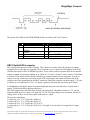
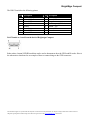
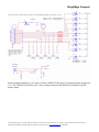
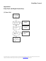
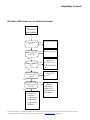
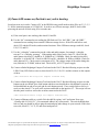
Roku BrightSign Compact Hardware Guide PCBA: C Version: .1 Saratoga, CA, USA 1 Table of Contents OVERVIEW ..................................................................................................................................... 3 PORTS .......................................................................................................................................... 5 POWER CONNECTOR ..................................................................................................................... 5 DB9 RS232 CONNECTOR .............................................................................................................. 5 DB15 SWITCH/LED CONNECTOR ................................................................................................... 6 ETHERNET .................................................................................................................................... 9 USB ............................................................................................................................................. 9 DB15 VGA CONNECTOR................................................................................................................ 9 TRIPLE RCA COMPONENT HD VIDEO CONNECTOR .......................................................................... 9 1/8” AUDIO CONNECTORS ............................................................................................................ 10 HDMI CONNECTOR ...................................................................................................................... 10 5V SERIAL CONNECTOR ............................................................................................................... 10 POWER USAGE ........................................................................................................................... 11 ENVIRONMENTAL ....................................................................................................................... 11 MECHANICAL............................................................................................................................... 12 THEORY OF OPERATION ........................................................................................................... 13 POWER SUPPLY .......................................................................................................................... 13 RESET ........................................................................................................................................ 13 PNX8935 CPU........................................................................................................................... 13 BUILT IN FLASH............................................................................................................................ 13 SDRAM ..................................................................................................................................... 13 SERIAL PORT .............................................................................................................................. 13 VIDEO ENCODER AND FILTER ....................................................................................................... 13 HDMI ENCODER .......................................................................................................................... 14 AUDIO OUTPUTS .......................................................................................................................... 14 ON BOARD LEDS ........................................................................................................................ 14 ON BOARD SWITCH ..................................................................................................................... 14 RESET SWITCH/GPIO BUTTON: .................................................................................................... 14 SDHC & SD FLASH SLOT ............................................................................................................ 14 NAND FLASH .............................................................................................................................. 15 ETHERNET .................................................................................................................................. 15 USB ........................................................................................................................................... 15 APPENDIX A................................................................................................................................. 16 FLOW CHART: (FOR REPAIR CENTER USE) ........................................................................... 16 (1) POWER START ....................................................................................................................... 16 (2) POWER LED COMES ON, NO SERIAL PORT OUTPUT................................................................... 17 GENERAL TROUBLESHOOTING NOTES:................................................................................. 19 1) •VTT (1.25V) SHOULD BE HALF OF VDD (2.5V) .................................................................... 19 2 BrightSign Compact Overview This hardware reference manual specifies the hardware interfaces on the Brightsign Compact, as well as providing a guide to troubleshoot the hardware of the Brightsign Compact for in-field service. This manual will not describe any software functions. The Brightsign Compact is a device that can be used to drive a variety of HDTV and computer monitors for digital sign and kiosk applications. As well as driving the Video Display, the Compact has many different control interfaces built in to allow the sign to be controlled. There are several different models of Brightsign Compact that Roku sells. This hardware manual will document all the features on the Compact, even though certain models of the Compact may not have every feature. For example, only some models of the Compact have the Ethernet interface. Brightsign This information applies to a product under development. Its characteristics and specifications are subject to change without notice. Roku assumes no obligation regarding future manufacturing unless otherwise agreed to in writing. www.rokulabs.com © Roku 2008 BrightSign Compact Compact Block Diagram This information applies to a product under development. Its characteristics and specifications are subject to change without notice. Roku assumes no obligation regarding future manufacturing unless otherwise agreed to in writing. www.rokulabs.com © Roku 2008 BrightSign Compact Ports On back of the unit: Power plug for 5V power input at 3A 10/100 Ethernet jack HDMI connector Triple RCA jacks for Component Hi-Def output (Y-Pr-Pb). DB15 VGA video connector. Stereo 1/8” mini plugs for audio output On the side of the unit: USB connector GPIO button Reset button On front of the unit: SD & SDHC flash card slot Green Flash Activity LED Green Power LED Red Status/Err LED Yellow Upgrade LED DA15 Female for GPIO, IR in & out, and 3.3V power. DB9 Male RS232 1/8” serial connector (0-5V serial) Note: Unless otherwise specified, Roku recommends that all cable lengths be 10 Meters or less. The customer may be able to use longer cables in specific cases, but the customer must test the cable to see if it will work. Generally higher quality cables with lower capacitances can be run longer than cheaper cables. Power Connector The power connector on our board is rated at 5V @ 3A. The plug to go into our connector is standard 5.5MM plug, center positive, with a 1.65MM center pin hole. The power is over voltage protected and reverse polarity protected with two 5W 6V zener diodes. Note that we actually supply our board with 5.2V in order to meet the HDMI specification, but we will refer to this voltage in this document as 5V. DB9 RS232 connector RS232 connector is a male DB9. The HD2000 is a DTE device (like a PC). The input to our chip accepts up to +25V and -25V, so it is compatible with standard +12 and -12 volt signaling. The output of our chip is rated at +5.4V and -5.4V typical which exceeds the voltage required by the RS232 specification. The baud rate is 115,200, No parity, 8 data bits, 1 stop bit. No hardware or software flow control. Maximum cable length is 50 Meters, total cable capacitance 2500pF (using lower capacitance cable allows longer than 50 Meters). The TX and RX signal will look like this: This information applies to a product under development. Its characteristics and specifications are subject to change without notice. Roku assumes no obligation regarding future manufacturing unless otherwise agreed to in writing. www.rokulabs.com © Roku 2008 BrightSign Compact The pinout of the DB9 on the REVB HD2000 board is as follows (NC=No Connect): pin Description 1 NC 3 Transmit data out of HD2000 5 Ground 7 Optional TX 2nd channel 9 NC pin Description 2 Receive data into HD2000 4 Available 5V @ 500mA 6 8 NC Optional RX 2nd channel DB15 Switch/LED connector The Switch/Led connector is a DB15 Female. This connector is used to allow the Compact to control external LEDs or other devices requiring 24mA of current or less. Connect the LED outputs to the LED ANODE and connect LED CATHODE to ground. If you want to connect up some other device then the output is capable of sourcing or sinking up to 24mA at 3.3V, but we do have a series resistor of 100 Ohms in each line. This connector also allows connecting up external contact closures to ground. In order to connect a switch, connect one side of the switch to the switch input, and connect the other side of the switch to one of the ground pins on the DB25 connector. Finally the connector can also supply 3.3V at up to 500mA to an external device. The 3.3V output is polyfuse protected and can source up to 500mA. If a Brightsign is driving the inputs on another Brightsign, then you can at most drive 3 inputs from 1 output. Calculations follow showing why this is: The GPIO outputs have 100 Ohm series resistors, the inputs have 1K pullup resistors to 3.3V, and the input threshold on the 541 chips is 2V high, and .8V low. The high voltage is not a problem, but the low voltage can be if there are too many inputs connected to 1 output. Here are the calculations: 1 out driving 1 in: V=3.3*100/(100+1000)=0.3 1 out driving 2 in: V=3.3*100/(100+500)=0.55 1 out driving 3 in: V=3.3*100/(100+333.3)=0.76 1 out driving 4 in: V=3.3*100/(100+250)=0.94 (Too high, so we can only let 1 output drive 3 inputs MAX!) This information applies to a product under development. Its characteristics and specifications are subject to change without notice. Roku assumes no obligation regarding future manufacturing unless otherwise agreed to in writing. www.rokulabs.com © Roku 2008 BrightSign Compact The DB15 female has the following pinout: pin 1 3 5 7 9 11 13 15 Description IR Blaster output Button 6 I/O Button 3 I/O Button 1 I/O Ground Ground Button 2 I/O Button 0 I/O pin 2 4 6 8 10 12 14 Description Ground Button 5 I/O Ground +3.3V output @ 500mA Button 7 I/O Button 4 I/O Ground DA15 female as viewed from the back of Brightsign Compact: Roku makes a button/LED/IR board that can be used to demonstrate how the GPIO and IR works. Here is the schematic to that board as an example of how to connect things to the GPIO connector: This information applies to a product under development. Its characteristics and specifications are subject to change without notice. Roku assumes no obligation regarding future manufacturing unless otherwise agreed to in writing. www.rokulabs.com © Roku 2008 BrightSign Compact In this example schematic, we are using a Vishay TSOP39338 IR receiver, which can operate properly on 3.3V. The TSOP39138 will also work. We are using a Honeywell SEP8506-003 IR Diode as the IR blaster output. This information applies to a product under development. Its characteristics and specifications are subject to change without notice. Roku assumes no obligation regarding future manufacturing unless otherwise agreed to in writing. www.rokulabs.com © Roku 2008 BrightSign Compact Ethernet The Brightsign Compact has a standard RJ45 connector for 10/100 base T Ethernet. Maximum cable length is 100 Meters. The pinout of the RJ45 is as follows: pin 1 3 5 7 Description TX+ RX+ RC to ground RC to ground pin 2 4 6 8 Description TXRC to ground RX RC to ground USB The Brightsign Compact has a high speed (480 mbit) USB host port. Maximum cable length is 5 Meters. The port has the following pinout: pin Description 1 VBUS 3 D+ pin Description 2 D4 Ground DB15 VGA connector The VGA connector is able to output RGB video. The connector has the following pinout: pin 1 3 5 7 9 11 13 15 Description RED analog video output BLUE analog video output Digital ground Analog ground +5V DDC supply NC HSYNC output DDC SCL pin 2 4 6 8 10 12 14 Description GREEN analog video output NC Analog ground Analog ground Digital ground DDC SDA VSYNC output Triple RCA Component HD video connector The component triple RCA connector is a able to output the following formats: 480P video: Y from Green jack, Pr from Red jack, and Pb from Blue jack. 720P video: Y from Green jack, Pr from Red jack, and Pb from Blue jack. This information applies to a product under development. Its characteristics and specifications are subject to change without notice. Roku assumes no obligation regarding future manufacturing unless otherwise agreed to in writing. www.rokulabs.com © Roku 2008 BrightSign Compact 1080i video: Y from Green jack, Pr from Red jack, and Pb from Blue jack. 1/8” Audio connectors The Brightsign Compact has one 1/8” female audio connectors. The connector has a stereo audio signal. The full scale voltage output of the audio is 2V RMS, with no load. The minimum load resistance that should be connected to the audio output is 5K Ohms. The connector is NOT capable of driving headphones directly. If you need to drive headphones, look into our Brightsign Expander module, which can drive 3 sets of 5 Ohm headphones directly. The audio connector has the following pinout: Tip: Left audio Ring: Right audio Base: Ground for audio signal HDMI connector The HDMI connector is used to send digital video and audio to HDMI enabled sink devices. This is the pinout of the HDMI connector: pin 1 3 5 7 9 11 13 15 17 19 Description TX2p TX2n Ground TX0p TX0n Ground CEC DDC SCL Ground HPD (Hot Plug Detect) pin 2 4 6 8 10 12 14 16 18 20 Description Ground TX1p TX1n Ground TXCp TXCn NC DDC SDA +5V DDC Ground 5V Serial connector The HD2000 has a single 1/8” female connector 5V serial access. This port is used to communicate with devices that require 0 and 5V serial signaling. This connector has the following pinout: Tip: Receive data Ring: Transmit data Base: Ground This information applies to a product under development. Its characteristics and specifications are subject to change without notice. Roku assumes no obligation regarding future manufacturing unless otherwise agreed to in writing. www.rokulabs.com © Roku 2008 BrightSign Compact Power usage The power supply on the Brightsign Compact is a 15W 5.2V @ 3A power supply. The Brightsign Compact will use approximately 1A of power when playing a 720p or 1080i MPEG2 HD source file. 1A at 5.2V is about 5W. This implies that there is 2A of additional available power that can be used by peripherals connected to the Brightsign Compact. The user should not connect up any combination of peripherals that will exceed 2A draw. If more than 2A is drawn, then the external power supply will shut down due to overcurrent conditions. The unit will not be damaged, but it may cause the unit to reboot or to not operate properly until the overload is removed. This 2A can be shared any way you like on the following connectors. Ethernet – About 180mA when transferring data USB – 1500mA max (USB spec is 500mA, but we decided to put out more current on the USB connector just like some PCs do, in order to be able to use the Brightsign Expander in some cases without an additional 5V power supply). DB9 5V – 500mA DB25 3.3V – 500mA HDMI 5V – 55mA max Each of 6 LED outputs on DB25 – up to 24mA each IR Blaster output – Up to 24mA Environmental The Brightsign Compact is designed to be used between the temperatures of 0 to 40C with 90% maximum relative humidity, non-condensing. This information applies to a product under development. Its characteristics and specifications are subject to change without notice. Roku assumes no obligation regarding future manufacturing unless otherwise agreed to in writing. www.rokulabs.com © Roku 2008 BrightSign Compact Mechanical This information applies to a product under development. Its characteristics and specifications are subject to change without notice. Roku assumes no obligation regarding future manufacturing unless otherwise agreed to in writing. www.rokulabs.com © Roku 2008 BrightSign Compact Theory of operation Power Supply The Brightsign Compact has a five voltages present. These are 5V, 3.3V, 2.5V, 1.8Vand 1.2V. 5V comes in from the power connector and is used directly for USB, the video filter chip.. 3.3V is created from 5V by a Semtech SC196 switching regulator. Similar regulators are used to create 2.5V for the DDR SDRAM, 1.8V for the HDMI chip, and 1.2V for the PNX8935 core voltage. Reset The Brightsign Compact has a Low Voltage Reset circuit made up of a ADM809SAKS. This circuit will hold the RESET_L signal low until a valid 3.3V power is present. PNX8935 CPU The Brightsign Compact has a Philips PNX8935 Multimedia CPU in it. This CPU runs on 3.3V, 2.5V, and 1.2V. The PNX8935 runs from a 27MHz oscillator. The PNX8935 is reset by the signal RESET_L from the low voltage reset circuit going into the RESET_IN pin on the PNX8935. When the RESET_IN pin goes from low to high, then the PNX8935 will boot from NAND flash. Built in Flash The HD2000 contains 3 flash devices. The boot code in the PNX8935 instructs the PNX8935 to continue the boot process by reading additional code from the on board NAND flash. This flash can be updated in the field, either from on the flash slots or USB mass storage. Part of the NAND flash is also used to hold non-volatile parameters. The contents of the boot flash is copied into the SDRAM, then the PNX8935 jumps to the boot code. There is also a serial settings flash that can be used to contain non-volatile settings. The last flash is the Ethernet flash that is used to configure the Ethernet PHY chip. SDRAM The HD2000 contains four DDR SDRAM devices. When the PNX8935 boots, it will copy the code from the NAND flash device into SDRAM, and then execute the code from SDRAM. The SDRAM runs at clock rate 200MHz, with data rate 400MHz. Serial Port The Brightsign Compact has a built in UART that that communicates with the RS232 level shifter. The MAX232 creates valid RS232 voltage levels for the transmit pin by using a capacitive voltage switcher. Video Encoder and Filter The PNX8935 streams decoded video out of the QVCP5L digital port using single data rate clock, and it also streams the same video out of the on board DACs. Analog video comes out of the PNX8935 and is connected to the FMS6203 video filter chip. This chip has a programmable cutoff frequency of either 8MHz, 16MHz or 32MHz, or no filter. Since the video filter has a low impedance output, we can drive both VGA and COMPONENT 75Ohm terminated cables at the same time with no degradation (with the This information applies to a product under development. Its characteristics and specifications are subject to change without notice. Roku assumes no obligation regarding future manufacturing unless otherwise agreed to in writing. www.rokulabs.com © Roku 2008 BrightSign Compact same signal). Some VGA monitors will sync at 720p and 1080i, so only in this case can a picture be displayed on both component and VGA at the same time. HDMI encoder The QVCP5L video is also sent over to the TDA9984B HDMI encoder chip, which drives the HDMI data out of the Brightsign Compact. The HDMI chip is also connected to I2S audio and SPDIF audio, so that audio will be driven out the HDMI connector. The TDA9984A is capable of upscaling video to 1080P. Audio outputs The Brightsign Compact has a single AK4420 high quality audio DAC device. This device take in digital audio signals from the PNX8935 for I2S audio. The AUD_LRCIN signal is the framing signal for the audio, running at the frame rate of the audio source. The frame rate is usually either 44.1KHz or 48KHz. AUD_BITCLK signal is typically 64 times higher than AUD_LRCIN. The AUD_MCLK is usually 4 times faster than the AUD_BITCLK signal. The I2S audio is also routed to the HDMI chip. The audio output from the AK4420 DAC is sent directly to the audio output jack. The AK4420 can drive a 5K load with a 2V RMS signal. On Board LEDs There are 4 on board LEDs, as follows: Green Flash Activity LED, one anytime the SD card is being accessed. Green Power LED, is on any time the board is powered up and not in reset. Yellow Upgrade LED, flashes when the board is being upgraded. Red Status/Err LED On Board Switch The on board switch is connected to a GPIO32. There is a pullup on the button so that GPIO32 is high normally, and it is pulled low when the button is pressed. Reset switch/GPIO button: The on board reset switch is connected to GPIO12. Pressing the reset button down will make GPIO12 go low. If you hold the reset button low for approximately 10 seconds, then the board will be hard reset. When the board goes into reset, then the power LED will go out until the reset button is released. SDHC & SD Flash Slot The SDHC & SD flash slot supports SHDC and SD flash cards. Power is controlled by internal mosfets inside the SMSC USB2250 USB Flash controller chip. This information applies to a product under development. Its characteristics and specifications are subject to change without notice. Roku assumes no obligation regarding future manufacturing unless otherwise agreed to in writing. www.rokulabs.com © Roku 2008 BrightSign Compact NAND flash The HD2000 has a built in NAND flash. All the code for the unit is stored on the NAND flash, and it may also be possible to store some content on the NAND flash. The NAND flash is connected to the PCI/XIO bus on the PNX8950. Ethernet 10/100 Base T Ethernet is implemented on the HD2000 by a Realtek RTL8100C PHY controller. This device takes the PNX8950 Ethernet signals and converts them to the differential Ethernet signals. The PHY chip is also connected to an on-board Ethernet magnetic and a RJ45 for cable termination. The DM9161 chip is able to signal to the PNX8950 that its state has changed by toggling the INT_ETH line, which is connected to GPIO11. USB The USB 2.0 High speed host controller is implemented internally inside the PNX8935 SOC chip. There is also a dual over-current protected switch TPS2069 device, which is used to turn on and off power to the USB device, and to detect over-current situations. This information applies to a product under development. Its characteristics and specifications are subject to change without notice. Roku assumes no obligation regarding future manufacturing unless otherwise agreed to in writing. www.rokulabs.com © Roku 2008 BrightSign Compact Appendix A Flow Chart: (for Repair Center Use) (1) Power Start No LEDs on Is the Output power adapter 5V DC? No Replace Power Adapter Is the Voltage of No Check D12 & D33 for shorts L2 = 5V? Yes Is the Voltage of TP16 3.3V? No Check U17, L3, C204 Yes Check U33, Reset circuit U36, R76, D5 This information applies to a product under development. Its characteristics and specifications are subject to change without notice. Roku assumes no obligation regarding future manufacturing unless otherwise agreed to in writing. www.rokulabs.com © Roku 2008 BrightSign Compact (2) Power LED comes on, no serial port output No serial port output Is there 2.5V DC at TP18? No Check U18, L5, C212 Is there 1.2V DC at TP20? No Check U20, L6, C223 Yes Is there 16MHz at TP7? No Check U3, Y3, C186, C187, R134, Nand flash U25 Yes Is RESET_L high at pin 1 of U15 after powerup? No Check U15, U36, S2 Yes Is SYS_RES_OUT_N No high at C188 after powerup? Yes Check U25 for good program and good solder joints, check SDRAM Check U3 Check nand contents U25, check nand bus, check sdram This information applies to a product under development. Its characteristics and specifications are subject to change without notice. Roku assumes no obligation regarding future manufacturing unless otherwise agreed to in writing. www.rokulabs.com © Roku 2008 BrightSign Compact (3) Power LED comes on, Red led is out, unit is booting. Serial port tests are in order. Connect a PC to the HD2000 using a null modem cable (Wire up 2-3, 3-2, 55). Set the terminal program to 115200,N,8,1. In order to see all boot messages, hold S1 down while powering the unit on or while using S2 to reset the unit. A) If the serial port is not working, then check U6 and P4. B) Use the “dir” command to test reading the SD flash card. Use “dir USB1:” and “dir USB2:” command to test reading from external USB mass storage devices. If the SD card fails to read, check U12 and the SD socket, and associated resistors. If the USB mass storage reads fail, check U30, U32, and P9. C) Use the “videoplay” command to test the video and audio outputs, for example “videoplay test.mp3” or “videoplay test.mpg”. If the analog audio fails to work, check U1. Check for the audio master clock on R7, should be 11.288MHz or 12.288MHz. Check for audio bit clock R9, should be ¼ of the MCLK. Check for LRCLK on R11, should be 44.1KHz or 48KHz. Check for audio data on R13. Check passives on outputs of U1. The voltage output of the audio during this test (fullscale) is 2V RMS, with no load. Check AUD_AVCC5V power supply. D) Connect a Roku Brightsign Compact Test board to the DA15. Run the following script to test the LEDs. If any LED fails to come on, then check U8, U9, U10, U11 and the resistors on the outputs of these. [TBD: Need GPIO LED script for Compact inserted here] E) Connect a Roku Brightsign Compact Test board to the DA15. Run the following script to test the buttons on the test board. Press each button and the screen should show which button is pressed. a led should blink on and off several ight for each button pressed. If any switch fails to read, or is stuck on, then check U7 as well as the resistors and beads on the inputs to U7. This script will test the side panel switch as well as the switches connected to the DA15. [TBD: Need GPIO button script for Compact inserted here] F) Connect a Ethernet cable to a switch. Exit the shell by typing “exit” and return. Now type “ifconfig eth0 192.168.1.21” (Use an unused address on your network). The switch should show link on, and you should be able to ping the unit and ping other things on your network. If this does not work, check U5, Y1, T1, P3 and associated passives. This information applies to a product under development. Its characteristics and specifications are subject to change without notice. Roku assumes no obligation regarding future manufacturing unless otherwise agreed to in writing. www.rokulabs.com © Roku 2008 BrightSign Compact General troubleshooting notes: 1) •VTT (1.25V) should be half of VDD (2.5V) This information applies to a product under development. Its characteristics and specifications are subject to change without notice. Roku assumes no obligation regarding future manufacturing unless otherwise agreed to in writing. www.rokulabs.com © Roku 2008