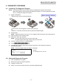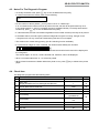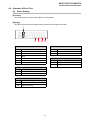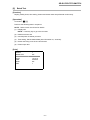
1
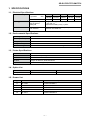
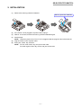
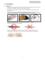
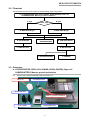
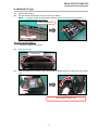
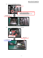
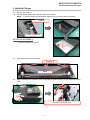
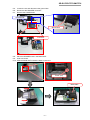
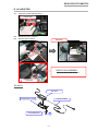
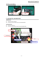
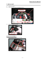
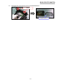
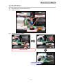
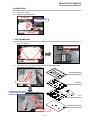
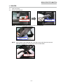
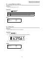
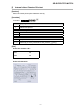
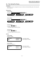
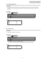
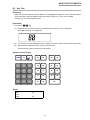
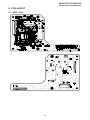
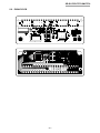
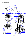
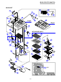
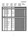
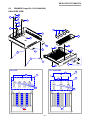
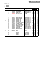
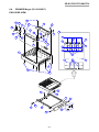
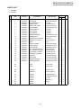
SERVICE MANUAL ELECTRONIC CASH REGISTER SE-G1/PCR-T273/SM-T274 (EX-256) JAN. 2013 Ver.1 : Jun. 2013 SE-G1/PCR-T273/SM-T274 CONTENTS 1.SPECIFICATIONS........................................................................................................... 1 2.INITIALIZATION .............................................................................................................. 2 3.DISASSEMBLY................................................................................................................ 3 4. DIAGNOSTIC OPERATION........................................................................................... 16 5. PCB LAYOUT................................................................................................................ 25 6. PARTS LIST................................................................................................................... 27 CAUTION RISK OF EXPLOSION IF BATTERY IS REPLACED BY AN INCORRECT TYPE. DISPOSE OF USED BATTERIES ACCORDING TO THE INSTRUCTIONS. SE-G1/PCR-T273/SM-T274 1. SPECIFICATIONS 1-1. Electrical Specifications Power Consumption In operation Max. 100 V 120 V 220 V 230 V 240 V 122 mA 111 mA 79 mA 75 mA 74 mA Mode off Max. 12.4 mA 11.4 mA 12 mA 12.4 mA 12.8 mA Memory protection Back-up battery Back-up period Battery life Mangan Battery (UM-3×2 pcs) 1 year (25 °C) Replace the battery every 1 years. Clock & Calendar Accuracy Auto calendar Within ± 30 sec. per month (25 °C) Effective until 2099 A.D. 1-2. Environmental Specifications Operating temperature 0 °C ~ 40 °C Operating humidity 10 % ~ 90 % Storage temperature -25 °C ~ 65 °C Storage humidity 10 % ~ 95 % Vibration strength Durable when one side of the unit is lifted to a height of 10 cm and dropped. 1-3. Printer Specifications Name LTP01-245 Method Thermal line dot printing Dots/line 384 dots/line Dot pitch Length 16 dots/mm, Wide 8 dots/mm Paper roll 58 mm × 80 mm φ (Max.) 1-4. Option List Name Waterproof Cover Model Note WT-92 1-5. Drawer List Type Model Specification S DL-1335 D-27L2C-D54RM-4 S DL-1844 D-27L2C-D53RM-4 S DL-1845 D-27L2C-D53RM-13 M DL-2816 D-25L2C-B84RM-4 M DL-2817 D-25L2C-B84RM-13 –1– SE-G1/PCR-T273/SM-T274 2. INITIALIZATION (1) Remove the memory protection batteries. Memory protection batteries (2) If the Power cord is plugged to a power outlet, unplug it. (3) Wait for 15 seconds, and set the memory protection batteries again. (4) Set the paper. NOTE: Unless the paper is set, Error "E 10" is triggered and the program cannot be launched. (5) Plug the Power cord to a power outlet. (6) Enter year, month, day, and time. NOTE: For US, enter month, day, and year in this order. For other regions, enter day, month, and year in this order. –2– SE-G1/PCR-T273/SM-T274 3. DISASSEMBLY 3-1. Important • Please note that the product on this manual may appear to be different from the actual one according to the changes such as engineering design change. • Be sure to unplug the power cord and remove the roll paper before starting any repair/ maintenance. • In order to prevent static and avoid leaving grease from the hand, wear conductive gloves, finger cots, or anti-static band when assembling/disassembling the product. • Do not use metal tweezers. Be sure to use plastic tweezers with flat tips. (Anti-static tweezers are recommended) • There are several kinds of screws. Be sure to use the correct type of screws when reassembling. It is advisable to sort the screws as shown below after removing them. –3– SE-G1/PCR-T273/SM-T274 3-2. Flowchart See the flowchart below for the order of disassembling major components. A. COVER/PRINTER, REEL (PULLY/WIND, SPOOL/PAPER), Paper roll, COVER/BATTERY, Memory protection batteries S Type B. MAIN-UNIT S-type D. AC-ADAPTOR M Type Drawer Type? C. MAIN-UNIT M-type E. ASSY/MOTOR, ASSY/MODE KEY G. PCB ASSY/E256-1 H. MOUNT/PCB F. DISPLAY UNIT I. KEY-BOARD-ASSY J. PRINTER 3-3. Procedure A. COVER/PRINTER, REEL (PULLY/WIND, SPOOL/PAPER), Paper roll COBER/BATTERY, Memory protection batteries A-1. Remove the COVER/PRINTER, REEL and Paper roll. Paper roll COVER/BATTERY SPOOL/PAPER Memory protection batteries PULLY/WIND COVER/PRINTER –4– SE-G1/PCR-T273/SM-T274 B. MAIN-UNIT S-type B-1. Remove the cable tie. B-2. Pull the drawer release lever and then remove the drawer. NOTE: In case the drawer is locked with a drawer lock key, the lever does not activate. Drawer release lever Cable tie NOTES ON ASSEMBLY • Be sure to attach the cable tie. B-3. Undo two screws. Screws (S1) B-4. Slide the MAIN UNIT toward the back. Disengage the MAIN UNIT as you pull out the AC power cord. Pull out the AC power cord. –5– SE-G1/PCR-T273/SM-T274 B-5. Disconnect the DRAWER connector. Connector NOTES ON ASSEMBLY Hook the DRAWER cable on the hook. DRAWER UNIT B-6. Undo three screws and remove the COVER/PCB. Screws (S2) MAIN UNIT COVER/PCB –6– SE-G1/PCR-T273/SM-T274 C. MAIN-UNIT M-type C-1. Remove the cable tie. C-2. Pull the drawer release lever and then remove the drawer. NOTE: In case the drawer is locked with a drawer lock key, the lever does not activate. Cable tie Drawer release lever NOTES ON ASSEMBLY • Be sure to attach the cable tie. C-3. Undo three screws and two plates. Screws (S3) Plates C-4. Slide the MAIN UNIT toward the back. Disengage the MAIN UNIT as you pull out the AC power cord. Pull out the AC power cord. –7– SE-G1/PCR-T273/SM-T274 C-5. Loosen the nut and disconnect the ground wire. C-6. Disconnect the DRAWER connector. C-7. Remove the COVER/PCB. COVER/PCB Ground wire Connector C-8. Place the DRAWER back in the MAIN UNIT. C-9. Undo one screw. C-10. Slide the MAIN UNIT toward the back to remove it. Screw (S4) MAIN UNIT –8– SE-G1/PCR-T273/SM-T274 D. AC-ADAPTOR D-1. Undo two screws. (M-type only) Screws (S3) D-2. Disconnect one connector. D-3. Remove the PS-ASSY. PS-ASSY NOTES ON ASSEMBLY Run the cable under the motor. Connector PS-ASSY PS-UNIT HOLDER/PS-CORD HOLDER/BUSH CORD/POWER S3 –9– SE-G1/PCR-T273/SM-T274 NOTES ON ASSEMBLY When the AC-ADAPTOR is replaced with a new part, attach the cable tie and tape. Cable tie Tape E. ASSY/MOTOR, ASSY/MODE KEY ASSY/MOTOR E-1. Disconnect one connector. E-2. Undo two screws and then remove the ASSY/MOTOR. ASSY/MODE KEY E-3. Disconnect one FFC. E-4. Undo one screw and then remove the ASSY/MODE KEY. Connector Screws (S3) FFC ASSY/MOTOR Screw (S3) – 10 – ASSY/MODE KEY SE-G1/PCR-T273/SM-T274 F. DISPLAY UNIT F-1. Undo four screws. F-2. Peel off the tape and then disengage the FFC. Screws (S7) FFC F-3. Remove the DISPLAY UNIT. DISPLAY UNIT NOTES ON ASSEMBLY Be sure that the LCD surfaces are clean. – 11 – Tape SE-G1/PCR-T273/SM-T274 F-4. Disengage two hooks and then remove the FRAME/DISPLAY. Hooks FRAME/DISPLAY – 12 – SE-G1/PCR-T273/SM-T274 G.PCB ASSY/E256-1 G-1. Disconnect one connector and two FFC. G-2. Undo two screws. Connector Screws (S4) FFC FFC G-3. Remove the E277-1-ASSY. Unhook the PCB. PCB ASSY/E256-1 – 13 – SE-G1/PCR-T273/SM-T274 H. MOUNT/PCB H-1. Undo three screws. H-2. Remove the MOUNT/PCB. Screws (S4) MOUNT/PCB Screw (S3) I. KEY-BOARD-ASSY I-1. Undo four screws. KEY-BOARD-ASSY Screws (S3) I-2. Undo two screws and then disassemble the KEY-BOARD-ASSY. SHEET/COMMON Screws (S8) SPACER CHASSIS/KEY BOARD FPC CHASSIS/KEY BOARD Hooks – 14 – SE-G1/PCR-T273/SM-T274 J. PRINTER J-1. Undo one screw. J-2. Remove the PRINTER. Screw (S3) PRINTER NOTE: The PLATEN ARM must be open to remove the PRINTER. ARM/PLATEN NOTE: When replacing the PRINTER with a new part, remove the roller from the new PRINTER and replace it with the roller for the PLATEN ARM. Roller – 15 – SE-G1/PCR-T273/SM-T274 4. DIAGNOSTIC PROGRAM 4-1. Launching The Diagnostic Program NOTE: If a receipt has been issued in other modes, the Diagnostic Program will not launch. When this happens, exit and restart the Diagnostic Program. To exit the Diagnostic Program, see "4-2. Exiting the Diagnostic Program". (1) Perform initialization. Memory protection batteries 1Remove the memory protection batteries. 2If the Power cord is plugged to a power outlet, unplug it. 3Wait for 15 seconds, and set the memory protection batteries again. (2) Set the paper. NOTE: Unless the paper is set, Error "E 10" is triggered and the program cannot be launched. (3) Plug the Power cord to a power outlet. (4) Enter year, month, day, and time. NOTE: For US, enter month, day, and year in this order. For other regions, enter day, month, and year in this order. (5) Insert the mode key and turn on [PGM MODE] (6) Press 99990000s. (7) The diagnostic program starts and the version information of the diagnostic program is automatically printed. NOTE: Once the program starts, the status is displayed. V. xxxx INI. • • • • • • • • • • • • • • • • x TEST • • • • • • • • 99990000 ←← Version ←← x=1: Except for US, x=2: US 4-2. Exiting the Diagnostic Program (1) Turn the Mode Switch to [OFF]. (2) Remove the memory protection batteries. (3) Unplug the Power Cord. (4) Wait for 15 seconds, and set the memory protection batteries again. – 16 – SE-G1/PCR-T273/SM-T274 4-3. Notes For The Diagnostic Program • To forcibly terminate a test, press y key or turn the Mode Switch to [OFF]. If a test is terminated, the device prints out the following: ESC • For the number of test to perform, you may select "once" or "infinite loop". If "0" is entered as the number of times to perform the test, the test will be performed only once. If any value between "1" and "9" is entered, the test is repeated infinitely. To forcibly terminate the infinite loop, press y key or turn the Mode Switch to [OFF]. • If a test result fails, the test is terminated regardless of the number of times previously set to perform. • If the Mode Switch is turned to [OFF] while the Diagnostic Program is running, the light on the 7-Segment turns off. Any command entered during this time is not accepted. • The winder motor rotates during printing. (No R/J switching function available.) • If a command of 8 digits or more is entered, the values entered initially are canceled. 2 5 5 2 5 5 1 1 3 0 s. If the above command is entered, the values indicated with double-lined boxes will be displayed in the 7-Segment. The first two digits, "2" and "5", will be canceled and, therefore, will not be displayed. • When a command starts with "0", "0" will not be printed. • When printed characters are hidden behind the printer cover, press f key to advance the printer paper. 4-4. Check Item This diagnostic program tests the following items. No. Item Operation Page 1 Status Display - 18 2 Batch Test (Display/ROM/Printer/Time Setting/Drawer/Buzzer) 1 19 3 Internal ROM Check SUM Test n518 20 4 Display Test 221 20 5 Internal Printer Character Print Test acn030 21 Time Setting hhmmss0070 yymmdd0170 Time Display 70 170 7 Drawer Open Test n091 23 8 Buzzer Test n092 23 9 Key Test 94 24 6 – 17 – 22 SE-G1/PCR-T273/SM-T274 4-5. Operation Of Each Test [1] Status Display [Function] The device status is indicated with ON/OFF of the segment. [Display] The figure below shows the relative display positions for the status information. 1 Mode Switch Display 4 Receipt Head Sensor Status Display Status 1 PGM On Head up 2 RF Off Head down 3 REG 4 CAL 5 X Display 6 Z On Battery level: Low or 0% Off Battery level: Normal 5 Memory Protection Batteries 2 PAD Terminal Display Status On Other than US Off US 3 Receipt Paper Display Status On No paper remaining Off Paper remaining – 18 – Status SE-G1/PCR-T273/SM-T274 [2] Batch Test [Function] Display, ROM, printer, time setting, drawer and buzzer tests are performed continuously. [Operation] Command : 1 k Performs the following tests in sequence. NOTE: Refer to each check item for details. (1) Display test NOTE: Press any key to go to the next test. (2) ROM check sum test (3) Internal printer character print test (4) Time setting: Set the default data (2012 December 31, 23:59'30). (5) Buzzer test: Ring once the one shot buzzer. (6) Drawer open test [Print] BATCH1 MASK CHK OK BBBBBBBBBBBBBBBBBBBBBBBB DATE12-12-31 TIME 23-59 30 DRWOK END1 – 19 – SE-G1/PCR-T273/SM-T274 [3] Internal ROM Check SUM Test [Function] Performs the ROM check sum test. [Operation] Command : n 5 1 8 k n: Number of times to run 0 1~9 Once (Can be omitted) Infinite loop (To forcibly terminate the test, press the y key.) [Print] MASK518 MASK CHK OK END518 [4] Display Test [Function] Tests the Main Display and the Customer Display. [Operation] Command : 2 2 1 k (7) Check that the segment shown below is indicated on the display. (8) To end the test, press y key. [PRINT] DISP221 DISP 7SEG OK END221 – 20 – SE-G1/PCR-T273/SM-T274 [5] Internal Printer Character Print Test [Function] Tests if the internal printer prints characters correctly. [Operation] Command : a c n 030k a: Printing property 0 Normal print out 1 Reduced size print out c: Characters to be printed 0 Prints the character “B” 1 Prints all characters n: Number of times to run 0 1~9 Once (Can be omitted) Infinite loop (To forcibly terminate the test, press the y key.) [Print] <Prints the character “B”> PRT30 BBBBBBBBBBBBBBBBBBBBBBBB END30 <Prints all characters> – 21 – SE-G1/PCR-T273/SM-T274 [6] Time Setting/Time Display [Function] Allows you to check or change the time (hour, minutes, seconds) and date (year, month, day) that are currently set. [Operation] <Time setting> Command : h hh h m m s s 0070k mm Hour Minutes ss Seconds dd Day • The new settings are printed out when the it is complete. <Date setting> Command : y yy y m m Year d d 0170k mm Month • The new settings are printed out when the it is complete. <Time display> Command : 0 7 0 k • To end the display, press the y key. <Date display> Command : 1 7 0 k • To end the display, press the y key. [Print] <Time setting> Example: 12:34’56 DATE/TIME1234560070 TIME12:34-56 END1234560070 ←← Command entered ←← New setting for the time <Date setting> Example: 2013 March 21 DATE/TIME1303210170 DATE13-03-21 END1303210170 ←← Command entered ←← New setting for the date – 22 – SE-G1/PCR-T273/SM-T274 [7] Drawer Open Test [Function] Tests whether drawers operate correctly. The drawer sensor checks every two seconds while the drawer open test is performed infinite times. Only when the drawer is closed, the drawer is reopened. [Operation] Command : n 0 9 1 k n: Number of times to run 0 1~9 Once (Can be omitted) Infinite loop (To forcibly terminate the test, press the y key.) [Print] DRW91 DRWOK END91 [8] Buzzer Test [Function] Tests whether buzzer sounds correctly. [Operation] Command : n 0 9 2 k n: Number of times to run 0 1~9 Once (Can be omitted) Infinite loop (To forcibly terminate the test, press the y key.) • If you select “once”, one-shot buzzer sounds. • If you select “infinite loop”, 500-msec intermittent buzzer sounds repeatedly. [Print] BUZZ92 END92 – 23 – SE-G1/PCR-T273/SM-T274 [9] Key Test [Function] Tests if keys are recognized correctly. Each key is assigned with a hard key code. This test checks if correct hard key cords are assigned. All keys except for l and y key may be tested. Pressing y key will terminate the test. [Operation] Command : 9 4 k (1) Press any key to display a hard key code assigned to the key on the 7-Segment. [Example of Display on 7-Segment] (2) To check if the number displayed on the 7-Segment is correct, refer to the Hard Key Code Chart. (3) When all keys are tested, press y key to end the test. Commands are printed out when the check ends. [Hard Key Code Chart] FEED 12 C 18 23 28 32 07 08 09 17 22 27 31 04 05 06 16 21 26 30 01 02 03 15 20 25 29 00 11 13 14 19 AC [Print] KEY94 ESC END94 – 24 – 24 SE-G1/PCR-T273/SM-T274 5. PCB LAYOUT 5-1. E256-1 PCB – 25 – SE-G1/PCR-T273/SM-T274 5-2. E256-E2 PCB – 26 – SE-G1/PCR-T273/SM-T274 6. EXPLODED VIEW/PARTS LIST MODEL : SE-G1/PCR-T723/SM-T274 (EX-256) <CONTENTS> 6-1. EXPLODE VIEW................................................................................................ 28 6-2. PARTS LIST....................................................................................................... 30 6-3. DRAWER S-type (DL-1335/1844/1845)............................................................ 33 6-4 DRAWER M-type (DL-2816/2817).................................................................... 35 NOTES : 1. Price and specifications are subject to change without prior notice. 2. As for spare parts order and supply, refer to the “GUIDEBOOK for Spare Parts Supply”, published separately. 3. The numbers in item column correspond to the same numbers in drawing. 4. CASIO does not supply the spare parts without parts code. 5. Refer to the latest "Parts Price Code" at “PARTS FINDER” on the Casio Service WEB site (https://www.servicecasio.com). 6. Remarks Q’ty: RANK: Quantity used per unit A = Essential B = Stock recommended C = Less recommended X = No stock recommended – 27 – SE-G1/PCR-T273/SM-T274 6-1. EXPLODED VIEW FINAL-ASSY 7 1 3 4 6 5 2 S-type M-type S4 MAIN-UNIT MAIN-UNIT 15 9 S3 11 S2 14 13 10 S1 DL-1335 DL-1844 DL-1845 8 DL-2816 DL-2817 12 EU &UK only S3 – 28 – 12 SE-G1/PCR-T273/SM-T274 MAIN-UNIT 29 26 S6 30 32 28 33 24 31 16 35 16 S3 S-type S3 M-type 34 27 S3 17 KEY-BOARD-ASSY S5 25 49 S3 50 21 S3 22 45 44 20 47 S3 43 19 S4 51 S7 18 48 42 DISPLAY 23 40 46 41 PCB ASSY/E256-1 S4 S8 37 36 38 18-1 39 S3 – 29 – FUSE SE-G1/PCR-T273/SM-T274 6-2. PARTS LIST 1SE-G1SB 2SE-G1SD 3SE-G1SG N 4SE-G1SA 5SE-G1SK 6SE-G1T Item Code No. FINAL-ASSY 1 1 2 2 3 3 3 3 4 5 6 7 8 9 10 11 11 12 13 14 15 15 10445446 10448039 10445448 10448040 10445449 10448287 10448044 10448041 10445436 10349665 10424040 10325051 10233584 10445447 10445450 10445437 10448042 10230087 10445438 10445439 10331637 10448043 S1 S2 S3 S4 7SE-G1MB 8SE-G1MG 9SE-G1MA Parts Name 10 SE-G1MK 11PCR-T273 12SE-G1SC Specification COVER/PRINTER/BK COVER/PRINTER/WE BOARD/RDP/BK BOARD/RDP/WE BOARD/DISPLAY BOARD/DISPLAY BOARD/DISPLAY BOARD/DISPLAY COVER/BATTERY PULLY/WIND SPOOL/PAPER SUB ASSY/KEY SET SEPARATER/BILL COVER/PCB COVER/CORD COVER/TOP/BK COVER/TOP/WE PLATE COVER/CORD COVER/PCB SUBASSY/TRAY SUBASSY/TRAY RJE504003-001V01 RJE504003-002V01 RJE504001-001V01 RJE504001-002V01 RJE504012-001V01 RJE504012-002V01 RJE504012-003V01 RJE504012-004V01 RJE504019-001V01 RJE501880-001V04 RJE502545-001V02 RJE503007*003V01 RJE500103-001V02 RJE504042-001V01 RJE504013-001V01 RJE504044-001V01 RJE504044-002V01 RJE500775-001V02 RJE504014-001V01 RJE504037-001V01 RJE503185*001V01 RJE503185*003V01 SCREW SCREW SCREW SCREW S-PAPT-3X16Z3 S-BDPT-3X10Z3 S-BDPT-3X8Z3 S-BDST-3X8ZC 16SM-T274 17SE-G1SD-WE 1 2 3 4 5 6 7 8 Q'TY 9 10 11 12 1 1 1 1 1 1 1 1 1 1 1 1 1 1 1 1 1 1 1 1 1 1 1 1 1 1 1 1 1 1 1 1 1 1 1 1 1 1 1 1 1 2 3 – 30 – 13SE-G1SB-WE 14SE-G1SK-WE 15SE-G1MB-WE 1 1 1 1 1 1 1 2 3 1 1 1 1 1 1 1 1 1 1 1 1 1 1 1 1 1 1 1 1 1 1 1 1 2 3 2 3 2 3 2 3 1 1 1 1 1 1 1 1 1 1 1 1 1 1 1 1 1 1 1 1 2 1 1 1 2 1 1 1 2 1 1 1 2 1 1 1 5 1 5 1 5 1 5 1 1 1 1 1 1 1 1 1 1 1 1 1 1 1 13 14 15 1 1 1 1 1 1 1 1 1 1 1 1 1 1 1 1 1 1 1 1 1 1 1 1 1 1 16 1 1 1 17 1 1 1 1 1 1 1 1 1 1 1 1 2 3 2 3 1 1 1 1 1 2 1 1 1 2 3 2 3 2 3 2 3 5 1 R C C C C C C C C C C C C C C C C C C C C C C SE-G1/PCR-T273/SM-T274 1SE-G1SB 2SE-G1SD 3SE-G1SG N 4SE-G1SA 5SE-G1SK 6SE-G1T 7SE-G1MB 8SE-G1MG 9SE-G1MA 10 SE-G1MK 11PCR-T273 12SE-G1SC Item Code No. Parts Name Specification U-CASE-ASSY 16 16 16 16 17 18 18 18-1 19 20 20 21 22 23 24 25 26 27 28 29 30 31 32 33 34 35 10445421 10448033 10445428 10448037 10448032 10450620 10450621 10225980 10450618 10445424 10448035 10445441 10445442 10445445 10445426 10334571 10445805 10236317 63452238 10294939 10294940 10350060 10347321 10451728 10445443 10445444 CASE/UPPER CASE/UPPER CASE/UPPER CASE/UPPER PRINTER PCB ASSY/E256-1 PCB ASSY/E256-1 FUSE DISPLAY UNIT FRAME/DISPLAY FRAME/DISPLAY MOUNT/PRINTER MOUNT/PCB CABLE/FFC/JOINER ROLLER/D-P ASSY/MODE KEY ARM/PLATEN CUTTER/PAPER SPRING/BATTERY/G55 SPRING/BATTERY/B-2E SPRING/BATTERY/G67E CABLE/SUBASSY/BATTERY MOUNT/MOTOR ASSY/MOTOR HOOK/R HOOK/L RJE503999-001V01 RJE503999-002V01 RJE504000-001V01 RJE504000-002V01 LTP01-245-02 TK-RJE504029*001V01 TK-RJE504029*002V01 230.600MXP RJE504067*001V01 RJE504043-001V01 RJE504043-002V01 RJE504002-001V01 RJE504005-001V01 RJE503998-001V01 RJE504041-001V01 TK-E341249*004V01 RJE504004-001V01 E441364-001V02 A42606B-1 RJE502620-001V01 RJE502622-001V01 RJE503227*001V02 RJE503259-001V01 TK-E441295*003 RJE504007-001V01 RJE504007-002V01 SCREW SCREW SCREW SCREW SCREW S-BDPT-3X8Z3 S-BDST-3X8ZC S-BDST-2X5X3 S-FLMA-3X4Z3 S-BDPT-3X810Z3 S3 S4 S5 S6 S7 – 31 – 13SE-G1SB-WE 14SE-G1SK-WE 15SE-G1MB-WE 1 2 3 4 5 6 1 1 1 1 1 1 7 8 Q'TY 9 10 1 1 1 1 16SM-T274 17SE-G1SD-WE 11 12 1 1 1 1 1 1 1 1 1 1 1 1 13 14 15 1 1 1 1 1 1 1 1 1 1 1 1 1 1 1 16 1 1 1 1 1 1 1 1 1 1 1 1 1 1 1 1 1 1 1 1 1 1 1 1 1 1 1 1 1 1 1 1 1 1 1 1 1 1 1 1 1 1 1 1 1 1 1 1 1 1 1 1 1 1 2 1 1 1 1 1 1 1 1 1 1 1 1 1 1 2 1 1 1 1 1 1 1 1 1 1 1 1 1 1 2 1 1 1 1 1 1 1 1 1 1 1 1 1 1 2 1 1 1 1 1 1 1 1 1 1 1 1 1 1 2 1 1 1 1 1 1 1 1 1 1 1 1 1 1 2 1 1 1 1 1 1 1 1 1 1 1 1 1 1 2 1 1 1 1 1 1 1 1 1 1 1 1 2 1 1 1 1 1 1 1 1 1 1 1 1 2 1 1 1 1 1 1 1 1 1 1 1 1 2 1 1 1 1 1 1 1 1 1 1 1 1 2 1 1 1 1 1 1 1 1 1 1 1 1 1 1 2 1 1 1 1 1 1 1 1 1 1 1 1 1 1 1 2 1 1 1 1 1 1 1 1 1 1 1 1 1 1 1 2 1 1 1 1 1 1 1 1 1 1 1 1 1 1 1 2 1 1 1 1 1 1 1 1 1 12 12 12 12 12 12 10 10 10 4 4 4 4 4 4 4 4 4 2 2 2 2 2 2 2 2 2 1 1 1 1 1 1 1 1 1 4 4 4 4 4 4 4 4 4 10 4 2 1 4 12 4 2 1 4 12 4 2 1 4 12 4 2 1 4 12 4 2 1 4 10 4 2 1 4 1 1 1 1 1 17 1 1 1 1 1 1 1 1 2 1 1 1 1 1 1 1 1 1 1 1 1 1 1 1 2 1 1 1 1 1 1 1 1 1 1 1 12 4 2 1 4 12 4 2 1 4 R C C C C A A A A A C C C C C C C C C C C C C X A X X SE-G1/PCR-T273/SM-T274 1SE-G1SB 2SE-G1SD 3SE-G1SG N 4SE-G1SA 5SE-G1SK 6SE-G1T Item Code No. PS-ASSY 36 37 38 38 38 38 38 39 10445391 10347349 10366973 10445415 10240096 10240097 10366975 10445392 S3 KEY-BOARD-ASSY 40 10442630 40 10394520 41 10436044 42 10451504 43 10451506 44 10451505 45 10193646 46 10193645 47 10324975 47 10347211 48 10324988 48 10347212 49 10370516 50 10370517 51 10167457 S8 7SE-G1MB 8SE-G1MG 9SE-G1MA Parts Name 10 SE-G1MK 11PCR-T273 12SE-G1SC Specification 13SE-G1SB-WE 14SE-G1SK-WE 15SE-G1MB-WE 1 2 3 4 5 6 7 8 1 1 1 1 1 1 1 1 1 1 1 1 1 1 1 1 1 16SM-T274 17SE-G1SD-WE Q'TY 9 10 11 12 13 14 15 16 17 1 1 1 1 1 1 1 1 1 1 1 1 1 1 1 1 1 1 1 1 HOLDER/PS-CORD PS-UNIT CORD/POWER CORD/POWER CORD/POWER CORD/POWER CORD/POWER HOLDER/BUSH RJE504022-001V01 S01258A LG276EU GL12080192 AR1CSEX270-UKLF AR1CSEX270-SAA-ALF TW15ES2SZC7S-LF RJE504017-001V01 1 1 1 1 1 1 1 1 1 1 1 1 1 1 1 1 1 1 1 1 1 SCREW S-BDPT-3X8Z3 1 1 1 1 1 1 1 1 1 1 1 1 1 1 1 1 1 FLAME/KEY BOARD/BK FLAME/KEY BOARD/WE CHASSIS/KEY BOARD FPC SPACER SHEET/COMMON SPRING/PRESS/B SPRING/PRESS/A KEY TOP/S/BK KEY TOP/S/WE KEY TOP/L/BK KEY TOP/L/WE CAP/S CAP/L RUBBER/CONTACT RJE502981-001V05 RJE502981-002V03 RJE503987-001V01 RJE503995-001V01 RJE503997-001V01 RJE501100-002V01 E441298-002V03 E441298-001V03 RJE502974-001V01 RJE502974-002V01 RJE502979-001V01 RJE502979-002V01 RJE502975-001V02 RJE502980-001V02 RJE501209-002V01 1 1 1 1 1 1 1 1 1 1 1 1 1 1 1 1 1 1 1 1 1 1 1 1 1 1 1 1 1 1 1 1 1 1 1 1 1 1 1 1 1 1 1 1 1 1 1 1 5 5 5 5 5 5 5 5 5 1 1 1 1 1 1 1 1 1 33 33 33 33 33 33 33 33 33 1 1 1 1 5 1 33 1 1 1 1 5 1 33 1 1 1 1 5 1 33 1 1 1 1 1 5 1 1 1 1 1 1 5 1 1 1 1 1 1 5 1 1 1 1 1 1 33 33 33 33 33 33 33 33 33 33 33 33 1 1 1 1 1 1 1 1 1 34 34 34 34 34 34 34 34 34 33 1 34 33 1 34 33 1 34 1 33 1 34 1 33 1 34 1 33 1 34 33 1 34 1 33 1 34 SCREW S-WLPT-3X8ZC 2 2 2 2 2 2 2 2 2 – 32 – 1 1 2 1 1 2 1 2 1 1 2 1 2 1 1 2 1 2 2 1 1 1 1 1 1 1 1 1 1 5 1 33 1 1 1 1 1 1 1 5 1 33 R C A C C C C C C C C X B C B C C C C C C A A B SE-G1/PCR-T273/SM-T274 6-3. DRAWER S-type (DL-1335/1844/1845) EXPLODED VIEW 9 S1 S1 7 5 4 8 2 17 1 16 6 W1 3 3 19 10 W1 6 6 3 18 20 DL-1844/1845 DL-1335 S1 12 S1 11 13 S2 14 14 15 15 – 33 – SE-G1/PCR-T273/SM-T274 PARTS LIST 1 2 3 N N DL-1335 DL-1844 DL-1845 Item Code No. 1 10449184 CASE/MAIN/BK RJE504018-001V01 Q'TY 1 2 3 1 1 1 10449188 CASE/MAIN/WE RJE504018-002V01 1 B 2 10449185 LEVER/HOOK RJE504008-001V01 1 1 1 C 3 10384548 ROLLER/PLASTIC PB-19B2 4 4 4 B 4 10201068 LOCK/SPRING RJE500007-001V02 1 1 1 C 5 10194207 SPRING/PRESS E412137-001V02 1 1 1 C 6 10167366 RUBBER/PAD RJE501204-001V01 5 5 5 C 7 10080189 SUB ASSY/SOLENOID E341255*2 1 1 1 B 8 10260417 AXIS/LEVER HOOK RJE502184-001V01 1 1 1 C 9 10267909 SPRING/PLUNGER RJE502245-001V01 1 1 1 C 10 10449179 CASE/BILL COIN RJE504011-001V01 10 10449176 CASE/BILL COIN RJE504011-002V01 10 10449182 CASE/BILL COIN RJE504011-003V01 11 10231347 SUB ASSY/BILL HOLDER RJE501337*001V03 12 10194229 PLATE/BILL HOLDER E341289-001V02 13 10230104 BILL HOLDER SUB ASSY E341290*002V04 14 10276626 SPRING/BILL HOLDER E441357-001V03 Parts Name Specification 1 B X 1 X 1 1 X X 1 4 R 1 X 3 3 C 3 3 X 15 10298553 PLATE/PARTITION RJE500214-002V03 3 2 2 C 16 10298558 CASE/COIN RJE500212-002V04 1 1 1 C 17 10298552 SEPARATER/COIN RJE500213-002V03 4 4 4 C 18 10447858 LOCK/CYRINDER RJE502350*002V01 1 1 1 C N 19 54400287 RIVETS/COLD HEADED 5X26 1 1 1 X N 20 55801452 CS FIX CSTW-5 1 1 1 X W1 WASHER 11.5X6.5XT0.8 2 2 2 X S1 SCREW S-PAPT-3X8Z3 5 5 5 X S2 SCREW S-PAST-3X5NI 3 3 – 34 – SE-G1/PCR-T273/SM-T274 6-4. DRAWER M-type (DL-2816/2817) EXPLODED VIEW S1 S2 S1 3 8 9 S1 11 7 S1 5 4 16 W1 N2 N1 S5 2 S4 S4 9 6 N1 19 S4 18 17 1 23 22 21 10 10 S6 2 13 W2 15 2 W2 12 14 S3 – 35 – S3 20 SE-G1/PCR-T273/SM-T274 PARTS LIST 1 DL-2816 2 DL-2817 N Item Code No. N 1 10445372 CASE/MAIN N Parts Name Specification RJE502983-002V02 Q'TY 1 2 1 R B 1 10447862 CASE/MAIN RJE502983-003V02 1 B 2 55000619 ROLLER/DELRIN DR-19B1 4 4 B 3 10236805 LEVER/HOOK E341286-001V03 1 1 C 4 10127603 AXIS/LEVER HOOK RJE500674-001V01 1 1 C 5 10201068 LOCK/SPRING RJE500007-001V02 1 1 C 6 62465010 SPRING/PRESS E412069-1 1 1 X 7 10078759 RAIL/MLED18 E240841-1 1 1 C 8 10078760 E240842-1 1 1 C RJE500005-001V02 4 4 X RJE501204-001V01 4 4 C 9 10194208 RAIL/MRED18 RUBBER/DUMPER 10 10167366 RUBBER/PAD 11 10080191 SOLENOIDO SUB ASSY E341301*4 1 1 B 12 10203849 DRAWER SUB ASSY E341274*001V03 1 1 C 13 52000106 RIVET 5X30 1 1 X N 14 10447858 LOCK/CYLINDER RJE502350*002V01 1 1 C N 15 10324878 PANEL/FRONT RJE502991-001V01 1 N N N C 15 10447857 PANEL/FRONT RJE502991-002V01 1 C 16 10445633 BILL COIN CASE ASSY RJE501368*10 1 1 C 17 10230104 BILL HOLDER SUB ASSY E341290*002V04 4 4 C 18 10276626 SPRING/BILL HOLDER E441357-001V03 4 4 A 19 10194233 PLATE/BILL HOLDER E240845-001V02 1 1 X 20 10445634 CASE/BILL RJE504023-001V01 1 1 X 21 10298559 CASE/COIN RJE500217-002V02 1 1 C 22 10298554 SEPARATER/COIN RJE500216-002V02 6 6 B 23 10298555 SEPARATER/BILL RJE500219-002V02 3 3 B N1 6-NUT N-HXT1-6Z3 2 2 N2 6-NUT N-HXT1-4Z3 1 1 W1 WASHER W-6X13-1.0Z3 2 2 W2 WASHER 6X13X1.0 ZMC-3 2 2 S1 SCREW S-WSPT-4X10Z3 6 6 S2 SCREW S-PADLMA-4X25Z3 1 1 S3 SCREW 3X10 NI 4 4 S4 SCREW 3X8 ZMC-3,, 3 3 S5 SCREW 3X5 NI... 4 4 S6 SCREW – 36 – Ver.1 : Jun. 2013 • Correction of the EXPLODED VIEW (P33) • Correction of the PARTS LIST (P34) CASIO COMPUTER CO., LTD. CS Technical Department TOKYO, JAPAN