1
Electric Drives and Controls Hydraulics Linear Motion and Assembly Technologies Pneumatics Rexroth IndraDyn T Synchronous-Torquemotors Project Planning Manual Service R911298798 Edition 03 Über diese Dokumentation Title Rexroth IndraDyn T Rexroth IndraDyn T Synchronous-Torquemotors Type of Documentation Document Typecode Internal File Reference Project Planning Manual DOK-MOTOR*-MBT********-PR03-EN-P • 29879803_Book.doc • Document Number 120-1500-B315-03/EN Purpose of Documentation This documentation.... • explains product features and applications, technical data as well as conditions and limits for operation. • provides guidlines for product selection, application, handling and operation. Record of Revisions Copyright Description Release Date Notes DOK-MOTOR*-MBT********-PR02-EN-P 06.2003 1 edition DOK-MOTOR*-MBT********-PR03-EN-P 08.2005 1 reprint st st Bosch Rexroth AG, 2005 Copying this document, giving it to others and the use or communication of the contents thereof without express authority, are forbidden. Offenders are liable for the payment of damages. All rights are reserved in the event of the grand of a patent or the registration of a utility model or design (DIN 34-1). Validity Published by The specified data is for product description purposes only and may not be deemed to be guaranteed unless expressly confirmed in the contract. All rights are reserved with respect to the content of this documentation and the availability of the product. Bosch Rexroth AG Bgm.-Dr.-Nebel-Str. 2 • D-97816 Lohr a. Main Telefon +49 (0)93 52 / 40-0 • Tx 68 94 21 • Fax +49 (0)93 52 / 40-48 85 http://www.boschrexroth.com/ Abt. BRC/EDM1 (FS) Note This document has been printed on chlorine-free bleached paper. DOK-MOTOR*-MBT********-PR03-EN-P Rexroth IndraDyn T Table of Contents I Table of Contents 1 Introduction to the Product 1.1 1-1 About this Documentation............................................................................................................. 1-2 Standards ................................................................................................................................ 1-3 Additional Components ........................................................................................................... 1-3 Feedback ................................................................................................................................. 1-3 2 Important directions for use 2.1 2-1 Appropriate use ............................................................................................................................ 2-1 Introduction .............................................................................................................................. 2-1 Areas of use and application ................................................................................................... 2-2 2.2 3 Inappropriate use.......................................................................................................................... 2-2 Safety Instructions for Electric Drives and Controls 3-1 3.1 Introduction ................................................................................................................................... 3-1 3.2 Explanations ................................................................................................................................. 3-1 3.3 Hazards by Improper Use............................................................................................................. 3-2 3.4 General Information ...................................................................................................................... 3-3 3.5 Protection Against Contact with Electrical Parts........................................................................... 3-5 3.6 Protection Against Electric Shock by Protective Low Voltage (PELV) ......................................... 3-6 3.7 Protection Against Dangerous Movements .................................................................................. 3-7 3.8 Protection Against Magnetic and Electromagnetic Fields During Operation and Mounting ....................................................................................................................................... 3-9 3.9 Protection Against Contact with Hot Parts.................................................................................. 3-10 3.10 Protection During Handling and Mounting.................................................................................. 3-10 3.11 Battery Safety ............................................................................................................................. 3-11 3.12 Protection Against Pressurized Systems.................................................................................... 3-11 4 Technical Data 4.1 4-1 Definitions ..................................................................................................................................... 4-1 Operating Modes ..................................................................................................................... 4-1 Duty Cycle ............................................................................................................................... 4-1 Characteristics ......................................................................................................................... 4-2 Operating Characteristics ........................................................................................................ 4-3 4.2 Data sheet, Size 130 .................................................................................................................... 4-4 Data Sheet for Frame Lengths 130A, 130C ............................................................................ 4-4 Data Sheet for Frame Lengths 130E, 130G............................................................................ 4-7 4.3 Data Sheet, Size 160.................................................................................................................. 4-10 4.4 Data Sheet, Size 210.................................................................................................................. 4-13 Data Sheet for Frame Lengths 210A, 210C, 210D ............................................................... 4-13 DOK-MOTOR*-MBT********-PR03-EN-P II Table of Contents Rexroth IndraDyn T Data Sheet for Frame Lengths 210E, 210R .......................................................................... 4-16 4.5 Data Sheet, Size 290.................................................................................................................. 4-19 4.6 Data Sheet, Size 360.................................................................................................................. 4-23 4.7 Data Sheet, Size 450.................................................................................................................. 4-26 4.8 Data Sheet, Size 530.................................................................................................................. 4-30 Data Sheet for Frame Lengths 530B, 530C, 530E................................................................ 4-30 Data Sheet, Sizes 530G, 530L .............................................................................................. 4-33 5 Dimension Sheets 5.2 5-1 Dimension Sheets, Size 130......................................................................................................... 5-2 Liquid Cooling .......................................................................................................................... 5-2 Natural Convection .................................................................................................................. 5-3 Rotor MRT130 ......................................................................................................................... 5-4 Rotor MRT130, mounted ......................................................................................................... 5-5 Stator MST130, liquid cooled .................................................................................................. 5-6 Stator MST130, natural convection ......................................................................................... 5-7 Stator MST130, liquid cooled, mounted .................................................................................. 5-8 Stator MST130, natural convection, mounted ......................................................................... 5-9 Rotor and Stator (nat. convection), mounted ........................................................................ 5-10 5.3 Dimension Sheets, Size 160....................................................................................................... 5-11 Rotor MRT160 ....................................................................................................................... 5-12 Rotor MRT160, mounted ....................................................................................................... 5-13 Stator MST160....................................................................................................................... 5-14 Stator MST160 in “Other Design” .....-D304 .......................................................................... 5-15 Stator MST160, mounted ...................................................................................................... 5-16 Rotor and Stator, mounted .................................................................................................... 5-17 5.4 Dimension Sheets, Size 210....................................................................................................... 5-18 Electrical Connection "SN" .................................................................................................... 5-18 Electrical Connection "CN" .................................................................................................... 5-19 Electrical Connection "RN" .................................................................................................... 5-20 Rotor MRT210 ....................................................................................................................... 5-21 Rotor MRT210, mounted ....................................................................................................... 5-22 Stator MST210, Electrical Connection "SN".......................................................................... 5-23 Stator MST210, Electrical Connection "CN".......................................................................... 5-24 Stator MST210, Electrical Connection “RN”.......................................................................... 5-25 Stator, mounted ..................................................................................................................... 5-26 Rotor and Stator, mounted .................................................................................................... 5-27 5.5 Dimension Sheets, Size 290....................................................................................................... 5-28 Electrical Connection "SN" .................................................................................................... 5-28 Electrical Connection "CN" .................................................................................................... 5-29 Electrical Connection "RN" .................................................................................................... 5-30 Rotor MRT290 ....................................................................................................................... 5-31 Rotor MRT290, mounted ....................................................................................................... 5-32 Stator MST290, Electrical Connection "SN".......................................................................... 5-33 Stator MST290, Electrical Connection "CN".......................................................................... 5-34 Stator MST290, Electrical Connection “RN”.......................................................................... 5-35 DOK-MOTOR*-MBT********-PR03-EN-P Rexroth IndraDyn T Table of Contents III Stator, mounted ..................................................................................................................... 5-36 Rotor and Stator, mounted .................................................................................................... 5-37 5.6 Dimension Sheets, Size 360....................................................................................................... 5-38 Electrical Connection "SN" .................................................................................................... 5-38 Electrical Connection "CN" .................................................................................................... 5-39 Electrical Connection "RN" .................................................................................................... 5-40 Rotor MRT360 ....................................................................................................................... 5-41 Rotor MRT360, mounted ....................................................................................................... 5-42 Stator MST360, Electrical Connection "SN".......................................................................... 5-43 Stator MST360, Electrical Connection "CN".......................................................................... 5-44 Stator MST360, Electrical Connection "RN".......................................................................... 5-45 Stator MST360, Electrical Connection "SN", mounted.......................................................... 5-46 Stator MST360, Electrical Connection "CN", mounted.......................................................... 5-47 Rotor and Stator, mounted .................................................................................................... 5-48 5.7 Dimension Sheets, Size 450....................................................................................................... 5-49 Electrical Connection "SN" .................................................................................................... 5-49 Electrical Connection "CN" .................................................................................................... 5-50 Electrical Connection "RN" .................................................................................................... 5-51 Rotor MRT450 ....................................................................................................................... 5-52 Rotor MRT450, mounted ....................................................................................................... 5-53 Stator MST450, Electrical Connection "SN".......................................................................... 5-54 Stator MST450, Electrical Connection "CN".......................................................................... 5-55 Stator MST450, Electrical Connection "RN".......................................................................... 5-56 Stator MST450, mounted ...................................................................................................... 5-57 Rotor and Stator, mounted .................................................................................................... 5-58 Dimension Sheets, Size 530................................................................................................................. 5-59 Electrical Connection "SN" .................................................................................................... 5-59 Electrical Connection "CN" .................................................................................................... 5-60 Electrical Connection "RN" .................................................................................................... 5-61 Rotor MRT530 ....................................................................................................................... 5-62 Rotor MRT530, mounted ....................................................................................................... 5-63 Stator MST530, Electrical Connection "SN".......................................................................... 5-64 Stator MST530, Electrical Connection "CN".......................................................................... 5-65 Stator MST530, Electrical Connection "RN".......................................................................... 5-66 Stator MST530, Electrical Connection "SN", mounted.......................................................... 5-67 Stator MST530, Electrical Connection "CN", mounted.......................................................... 5-68 Rotor and Stator, mounted .................................................................................................... 5-69 Stator MST530, Cooling Type "S" ......................................................................................... 5-70 6 Type Codes 6-1 Type Codes for Rotor MRT ..................................................................................................... 6-1 Type Codes for Stator MST..................................................................................................... 6-2 6.2 Size 130 ........................................................................................................................................ 6-3 Rotor MRT130 ......................................................................................................................... 6-3 Stator MST130......................................................................................................................... 6-4 6.3 Size 160 ........................................................................................................................................ 6-5 DOK-MOTOR*-MBT********-PR03-EN-P IV Table of Contents Rexroth IndraDyn T Rotor MRT160 ......................................................................................................................... 6-5 Stator MST160......................................................................................................................... 6-5 6.4 Size 210 ........................................................................................................................................ 6-6 Rotor MRT210 ......................................................................................................................... 6-6 Stator MST210......................................................................................................................... 6-7 6.5 Size 290 ........................................................................................................................................ 6-8 Rotor MRT290 ......................................................................................................................... 6-8 Stator MST290......................................................................................................................... 6-8 6.6 Size 360 ........................................................................................................................................ 6-9 Rotor MRT360 ......................................................................................................................... 6-9 Stator MST360......................................................................................................................... 6-9 6.7 Size 450 ...................................................................................................................................... 6-10 Rotor MRT450 ....................................................................................................................... 6-10 Stator MST450....................................................................................................................... 6-10 6.8 Size 530 ...................................................................................................................................... 6-11 Rotor MRT530 ....................................................................................................................... 6-11 Stator MST530....................................................................................................................... 6-12 7 Accessories 7.1 7-1 Mounting Ring............................................................................................................................... 7-1 Construction............................................................................................................................. 7-1 Order........................................................................................................................................ 7-2 Handling................................................................................................................................... 7-2 Dimension Sheet for Mounting Ring in SUP-M01-MBT450 .................................................... 7-4 Dimension Sheet for Mounting Ring in SUP-M02-MBT450 .................................................... 7-5 Dimension Sheet for Mounting Ring in SUP-M01-MBT530 .................................................... 7-6 Dimension Sheet for Mounting Ring in SUP-M02-MBT530 .................................................... 7-7 Dimension Sheet for Mounting Ring in SUP-M03-MBT530 .................................................... 7-8 8 Connection Techniques 8-1 8.1 Notes............................................................................................................................................. 8-1 8.2 Connection Cables ....................................................................................................................... 8-2 8.3 Connection with Terminal Box ...................................................................................................... 8-6 Terminal Box............................................................................................................................ 8-6 8.4 Connection with Coupling ............................................................................................................. 8-8 Coupling and Connector.......................................................................................................... 8-8 8.5 Sensors......................................................................................................................................... 8-9 Encoder ................................................................................................................................... 8-9 Temperature Sensors.............................................................................................................. 8-9 8.6 Motor Cooling ............................................................................................................................. 8-10 Operating Pressure ............................................................................................................... 8-10 9 Application Notes 9.1 9-1 Conditions for Use ........................................................................................................................ 9-1 Setup Elevation and Ambient Temperature ............................................................................ 9-1 9.2 Ambient Conditions....................................................................................................................... 9-1 DOK-MOTOR*-MBT********-PR03-EN-P Rexroth IndraDyn T Table of Contents V 9.3 International Protection Class....................................................................................................... 9-3 9.4 Compatibility ................................................................................................................................. 9-3 9.5 Motor Cooling System .................................................................................................................. 9-3 Coolants................................................................................................................................... 9-4 Used Materials......................................................................................................................... 9-5 Coolant Inlet Temperature....................................................................................................... 9-5 Operation without Liquid Coolant ............................................................................................ 9-6 Rotor Temperature .................................................................................................................. 9-6 9.6 Motor Temperature Overview ....................................................................................................... 9-6 9.7 Fastening ...................................................................................................................................... 9-9 Stator ....................................................................................................................................... 9-9 Rotor ...................................................................................................................................... 9-10 9.8 Rotor Direction of Rotation ......................................................................................................... 9-11 9.9 Foreign Components .................................................................................................................. 9-12 10 Handling and Transport 10-1 10.1 Supplied Condition...................................................................................................................... 10-1 Factory Inspection ................................................................................................................. 10-1 Inspection by Customer......................................................................................................... 10-1 Scope of Delivery................................................................................................................... 10-2 10.2 Transport and Storage................................................................................................................ 10-2 Transport ............................................................................................................................... 10-4 Storage .................................................................................................................................. 10-4 11 Installation 11-1 11.1 Safety.......................................................................................................................................... 11-1 11.2 Mounting Ring............................................................................................................................. 11-1 11.3 Mechanical Installation ............................................................................................................... 11-2 Preparation ............................................................................................................................ 11-2 Assembly without Mounting Ring .......................................................................................... 11-4 Assembly with Mounting Ring (Optional) .............................................................................. 11-6 11.4 Electrical Connection .................................................................................................................. 11-8 11.5 Coolant Connection .................................................................................................................... 11-9 12 Operating Torque Motors 12-1 12.1 General Notes Regarding Commissioning ................................................................................. 12-1 Preparation ............................................................................................................................ 12-1 Execution ............................................................................................................................... 12-1 12.2 Commissioning ........................................................................................................................... 12-2 12.3 General Preconditions ................................................................................................................ 12-3 Check of All Electrical and Mechanical Components ............................................................ 12-3 Tools ...................................................................................................................................... 12-4 12.4 General Commissioning Procedure............................................................................................ 12-5 12.5 Parameter Value Assignment..................................................................................................... 12-6 Entering Motor Parameters ................................................................................................... 12-6 Input of the Parameters of the Encoder System ................................................................... 12-8 DOK-MOTOR*-MBT********-PR03-EN-P VI Table of Contents Rexroth IndraDyn T Input of Drive Limitations and Application-Related Parameters............................................ 12-8 12.6 Determining the Polarity of the Encoder System........................................................................ 12-9 12.7 Commutation Adjustment ......................................................................................................... 12-10 12.8 Setting and Optimizing the Control Loop.................................................................................. 12-12 General Sequence............................................................................................................... 12-12 12.9 Deactivation .............................................................................................................................. 12-14 12.10 Dismantling ............................................................................................................................... 12-14 12.11 Maintenance ............................................................................................................................. 12-15 Measures ............................................................................................................................. 12-15 Coolant Supply .................................................................................................................... 12-15 12.12 Troubleshooting ........................................................................................................................ 12-16 Excess Temperature of Motor Housing............................................................................... 12-17 High Motor Temperature Values, but Housing Temperature is Normal .............................. 12-17 Motor or Machine Generates Vibrations.............................................................................. 12-18 Specified Position is not Attained ........................................................................................ 12-18 Waste Disposal ................................................................................................................................... 12-19 13 Service & Support 13-1 13.1 Helpdesk ..................................................................................................................................... 13-1 13.2 Service-Hotline ........................................................................................................................... 13-1 13.3 Internet........................................................................................................................................ 13-1 13.4 Vor der Kontaktaufnahme... - Before contacting us... ................................................................ 13-2 13.5 Kundenbetreuungsstellen - Sales & Service Facilities ............................................................... 13-2 14 Appendix for Motor Size 210R 14-1 14.1 General ....................................................................................................................................... 14-1 14.2 Dimension Sheet, MBT210R ...................................................................................................... 14-2 14.3 Installation................................................................................................................................... 14-3 Mechanical Installation .......................................................................................................... 14-3 Preparation ............................................................................................................................ 14-3 Assembly ............................................................................................................................... 14-4 Electrical Connection............................................................................................................. 14-6 Coolant Connection ............................................................................................................... 14-6 14.4 Accessories ................................................................................................................................ 14-6 Dimension Sheet, SUP-M04-MBT210................................................................................... 14-7 15 Appendix for Motor Sizes 530G and 530L 15-1 15.1 General ....................................................................................................................................... 15-1 15.2 Dimension Sheet, MBT530G / 530L........................................................................................... 15-2 Dimension Sheet, Rotor MRT530G / MRT530L.................................................................... 15-3 Dimension Sheet, Stator MST530G / MST530L ................................................................... 15-4 15.3 Shaft End Dimensioning ............................................................................................................. 15-5 Shaft Dimensioning ............................................................................................................... 15-6 15.4 Stator Assembly.......................................................................................................................... 15-7 Installation Dimension Sheet, MST530G / 530L ................................................................... 15-8 15.5 Assembly of the Rotor ................................................................................................................ 15-9 DOK-MOTOR*-MBT********-PR03-EN-P Rexroth IndraDyn T Table of Contents VII Installation Dimension Sheet, Rotor MRT530G / MRT530L ............................................... 15-10 Mounting Tool for Rotor (Example) ..................................................................................... 15-11 15.6 Assembling the Motor Encoder and the Covers ....................................................................... 15-12 Installation Dimension Sheet, MBT530G / 530L ................................................................. 15-13 16 Index DOK-MOTOR*-MBT********-PR03-EN-P 16-1 VIII Table of Contents Rexroth IndraDyn T DOK-MOTOR*-MBT********-PR03-EN-P Introduction to the Product 1-1 Rexroth IndraDyn T 1 Introduction to the Product The IndraDyn T series of synchronous torque motors from Bosch Rexroth consist of a stator and a rotor – the MST and MRT, respectively. The stator comes with a laminated core with multipolar winding, a liquid cooling jacket and a connecting cable. The rotor is fitted with permanent magnets. Stator Rotor Mbt1.EPS Fig. 1-1: IndraDyn T units IndraDyn T synchronous torque motors have a high torque with an optimum residual ripple. These motors are extremely well-suited for compact direct drives for rotary tables. In comination with digital control devices from the INDRADRIVE, DIAX or ECODRIVE series, the IndraDyn T series forms an intelligent drive solution with a high power density and open functions. The following diagram provides an overview of the torque spectrum of IndraDyn T synchronous torque motors from Bosch Rexroth. 14000 Drehmoment / Torque [Nm] 12000 10000 8000 6000 4000 2000 R L G E D Baulänge / motor length C B 0 530 450 360 290 Baugröße / motor size 210 A 160 130 Fig. 1-2: DOK-MOTOR*-MBT********-PR03-EN-P IndraDyn T overview 1-2 Introduction to the Product 1.1 Rexroth IndraDyn T About this Documentation Document Structure This documentation includes safety regulations, technical data and operating instructions. The following provides an overview of the contents of this documentation. Chap. Title 1 Introduction 2 Important Instructions on Use 3 Safety 4 Technical Data 5 Dimension Sheets 6 Type Codes 7 Accessories 8 Connection Techniques 9 Notes on Application 10 Handling & Transport 11 Installation 12 Operation 13 Service and Support 14 Appendix for Motor Size 210R 15 Appendix for Motor Sizes 530G/L 16 Index Introduction to the product and notes Important safety notes Product description for planners and designers Practice for operating and maintenance personnel Product description for planners and designers Additional information Fig. 1-3: Chapter structure Additional Documentation To design IndraDyn T motor type drive systems, you may need additional documentation, depending on the devices used. Rexroth has made the entire product documentation available on DVD in PDF format or in the Internet under www.boschrexroth.com/BrcDoku/ (one-time registration required). The documentation on the DVD as a whole is not necessary to projecting individual systems. Note: The entire documentation is also available in hard copy. You can order the necessary documentation through your local Rexroth representation. Material No. Title / description R911281882 -Produktdokumentation Electric Drives and Controls Version xx DOK-GENRL-CONTR*DRIVE-GNxx-DE-D650 (German) R911281883 -Product Documentation Electric Drives and Controls Version xx DOK-GENRL-CONTR*DRIVE-GNxx-EN-D650 (English) 1) 1) 1) The index (e.g. ...02-...) identifies the version. Fig. 1-4: Additional documentation DOK-MOTOR*-MBT********-PR03-EN-P Introduction to the Product 1-3 Rexroth IndraDyn T Standards This documentation refers to German, European and international technical standards. Documents and sheets on standards underlie contact: BEUTH Verlag GmbH Burggrafenstrasse 6 10787 Berlin Phone +49-(0)30-26 01-22 60, Fax +49-(0)30-26 01-12 60 Internet: http://www.din.de/beuth [email protected] Additional Components Documentation for external systems which are connected to Bosch Rexroth components is not included in the scope of delivery and must be ordered directly from the particular manufacturers. For information on the manufacturers, see chapter 9 “Application Notes”. Feedback Your experiences are an essential part of the process of improving both the product and the documentation. Please do not hesitate to inform us of any mistakes you detect in this documentation or of any modifications you might desire. We would appreciate your feedback. Please send your remarks to: BOSCH Rexroth Electric Drives and Controls GmbH Dep. BRC/EDM1 Bürgermeister-Dr.-Nebel-Straße 2 D-97816 Lohr, Germany Fax +49 (0) 93 52 / 40-43 80 DOK-MOTOR*-MBT********-PR03-EN-P 1-4 Introduction to the Product Rexroth IndraDyn T DOK-MOTOR*-MBT********-PR03-EN-P Important directions for use 2-1 Rexroth IndraDyn T 2 Important directions for use 2.1 Appropriate use Introduction Bosch Rexroth products represent state-of-the-art developments and manufacturing. They are tested prior to delivery to ensure operating safety and reliability. The products may only be used in the manner that is defined as appropriate. If they are used in an inappropriate manner, then situations can develop that may lead to property damage or injury to personnel. Note: Bosch Rexroth, as manufacturer, is not liable for any damages resulting from inappropriate use. In such cases, the guarantee and the right to payment of damages resulting from inappropriate use are forfeited. The user alone carries all responsibility of the risks. Before using Bosch Rexroth products, make sure that all the prerequisites for appropriate use of the products are satisfied: • Personnel that in any way, shape or form uses our products must first read and understand the relevant safety instructions and be familiar with appropriate use. • If the product takes the form of hardware, then they must remain in their original state, in other words, no structural changes are permitted. It is not permitted to decompile software products or alter source codes. • Do not mount damaged or faulty products or use them in operation. • Make sure that the products have been installed in the manner described in the relevant documentation. DOK-MOTOR*-MBT********-PR03-EN-P 2-2 Important directions for use Rexroth IndraDyn T Areas of use and application Rexroth IndraDyn T motors are designed to be used as rotary drive motors in machines. Several types of motors with differing drive power and different interfaces are available for application-specific uses. Control and monitoring of the motors may require additional sensors and actors. Note: The motors may only be used with the accessories and parts specified in this document. If a component has not been specifically named, then it may not be either mounted or connected. The same applies to cables and lines. Operation is only permitted in the specified configurations and combinations of components using the software and firmware as specified in the relevant function descriptions. Every drive controller has to be programmed before starting it up, making it possible for the motor to execute the specific functions of an application. The motors may only be operated under the assembly, installation and ambient conditions as described here (temperature, system of protection, humidity, EMC requirements, etc.) and in the position specified. 2.2 Inappropriate use Inappropriate use is defined as using the motors outside of the abovereferenced areas of application or under operating conditions other than described in the document and the technical data specified. IndraDyn T motors may not be used if • they are subject to operating conditions that do not meet the above specified ambient conditions. This includes, for example, operation under water, in the case of extreme temperature fluctuations or extremely high maximum temperatures or if • Bosch Rexroth has not specifically released them for that intended purpose. Please note the specifications outlined in the general Safety Guidelines! DOK-MOTOR*-MBT********-PR03-EN-P Safety Instructions for Electric Drives and Controls 3-1 Rexroth IndraDyn T 3 Safety Instructions for Electric Drives and Controls 3.1 Introduction Read these instructions before the initial startup of the equipment in order to eliminate the risk of bodily harm or material damage. Follow these safety instructions at all times. Do not attempt to install or start up this equipment without first reading all documentation provided with the product. Read and understand these safety instructions and all user documentation of the equipment prior to working with the equipment at any time. If you do not have the user documentation for your equipment, contact your local Bosch Rexroth representative to send this documentation immediately to the person or persons responsible for the safe operation of this equipment. If the equipment is resold, rented or transferred or passed on to others, then these safety instructions must be delivered with the equipment. WARNING 3.2 Improper use of this equipment, failure to follow the safety instructions in this document or tampering with the product, including disabling of safety devices, may result in material damage, bodily harm, electric shock or even death! Explanations The safety instructions describe the following degrees of hazard seriousness in compliance with ANSI Z535. The degree of hazard seriousness informs about the consequences resulting from noncompliance with the safety instructions. Warning symbol with signal word Degree of hazard seriousness according to ANSI Death or severe bodily harm will occur. DANGER Death or severe bodily harm may occur. WARNING Bodily harm or material damage may occur. CAUTION Fig. 3-1: DOK-MOTOR*-MBT********-PR03-EN-P Hazard classification (according to ANSI Z535) 3-2 Safety Instructions for Electric Drives and Controls 3.3 Rexroth IndraDyn T Hazards by Improper Use High voltage and high discharge current! Danger to life or severe bodily harm by electric shock! DANGER Dangerous movements! Danger to life, severe bodily harm or material damage by unintentional motor movements! DANGER High electrical voltage due to wrong connections! Danger to life or bodily harm by electric shock! WARNING Health hazard for persons with heart pacemakers, metal implants and hearing aids in proximity to electrical equipment! WARNING Surface of machine housing could be extremely hot! Danger of injury! Danger of burns! CAUTION CAUTION Risk of injury due to improper handling! Bodily harm caused by crushing, shearing, cutting and mechanical shock or incorrect handling of pressurized systems! Risk of injury due to incorrect handling of batteries! CAUTION DOK-MOTOR*-MBT********-PR03-EN-P Safety Instructions for Electric Drives and Controls 3-3 Rexroth IndraDyn T 3.4 General Information • Bosch Rexroth AG is not liable for damages resulting from failure to observe the warnings provided in this documentation. • Read the operating, maintenance and safety instructions in your language before starting up the machine. If you find that you cannot completely understand the documentation for your product, please ask your supplier to clarify. • Proper and correct transport, storage, assembly and installation as well as care in operation and maintenance are prerequisites for optimal and safe operation of this equipment. • Only persons who are trained and qualified for the use and operation of the equipment may work on this equipment or within its proximity. • The persons are qualified if they have sufficient knowledge of the assembly, installation and operation of the equipment as well as an understanding of all warnings and precautionary measures noted in these instructions. • Furthermore, they must be trained, instructed and qualified to switch electrical circuits and equipment on and off in accordance with technical safety regulations, to ground them and to mark them according to the requirements of safe work practices. They must have adequate safety equipment and be trained in first aid. • Only use spare parts and accessories approved by the manufacturer. • Follow all safety regulations and requirements for the specific application as practiced in the country of use. • The equipment is designed for installation in industrial machinery. • The ambient conditions given in the product documentation must be observed. • Use only safety features and applications that are clearly and explicitly approved in the Project Planning Manual. If this is not the case, they are excluded. The following areas of use and application, for example, include safety features and applications: construction cranes, elevators used for people or freight, devices and vehicles to transport people, medical applications, refinery plants, transport of hazardous goods, nuclear applications, applications in which electrical devices with vital functions can be electromagnetically disturbed, mining, food processing, control of protection equipment (also in a machine). • The information given in the documentation of the product with regard to the use of the delivered components contains only examples of applications and suggestions. The machine and installation manufacturer must • make sure that the delivered components are suited for his individual application and check the information given in this documentation with regard to the use of the components, • make sure that his application complies with the applicable safety regulations and standards and carry out the required measures, modifications and complements. • Startup of the delivered components is only permitted once it is sure that the machine or installation in which they are installed complies with the national regulations, safety specifications and standards of the application. DOK-MOTOR*-MBT********-PR03-EN-P 3-4 Safety Instructions for Electric Drives and Controls Rexroth IndraDyn T • Operation is only permitted if the national EMC regulations for the application are met. The instructions for installation in accordance with EMC requirements can be found in the documentation "EMC in Drive and Control Systems". The machine or installation manufacturer is responsible for compliance with the limiting values as prescribed in the national regulations. • Technical data, connections and operational conditions are specified in the product documentation and must be followed at all times. DOK-MOTOR*-MBT********-PR03-EN-P Safety Instructions for Electric Drives and Controls 3-5 Rexroth IndraDyn T 3.5 Protection Against Contact with Electrical Parts Note: This section refers to equipment and drive components with voltages above 50 Volts. Touching live parts with voltages of 50 Volts and more with bare hands or conductive tools or touching ungrounded housings can be dangerous and cause electric shock. In order to operate electrical equipment, certain parts must unavoidably have dangerous voltages applied to them. High electrical voltage! Danger to life, severe bodily harm by electric shock! DANGER DOK-MOTOR*-MBT********-PR03-EN-P ⇒ Only those trained and qualified to work with or on electrical equipment are permitted to operate, maintain or repair this equipment. ⇒ Follow general construction and safety regulations when working on high voltage installations. ⇒ Before switching on power the ground wire must be permanently connected to all electrical units according to the connection diagram. ⇒ Do not operate electrical equipment at any time, even for brief measurements or tests, if the ground wire is not permanently connected to the points of the components provided for this purpose. ⇒ Before working with electrical parts with voltage higher than 50 V, the equipment must be disconnected from the mains voltage or power supply. Make sure the equipment cannot be switched on again unintended. ⇒ The following should be observed with electrical drive and filter components: ⇒ Wait thirty (30) minutes after switching off power to allow capacitors to discharge before beginning to work. Measure the voltage on the capacitors before beginning to work to make sure that the equipment is safe to touch. ⇒ Never touch the electrical connection points of a component while power is turned on. ⇒ Install the covers and guards provided with the equipment properly before switching the equipment on. Prevent contact with live parts at any time. ⇒ A residual-current-operated protective device (RCD) must not be used on electric drives! Indirect contact must be prevented by other means, for example, by an overcurrent protective device. ⇒ Electrical components with exposed live parts and uncovered high voltage terminals must be installed in a protective housing, for example, in a control cabinet. 3-6 Safety Instructions for Electric Drives and Controls Rexroth IndraDyn T To be observed with electrical drive and filter components: High electrical voltage on the housing! High leakage current! Danger to life, danger of injury by electric shock! DANGER 3.6 ⇒ Connect the electrical equipment, the housings of all electrical units and motors permanently with the safety conductor at the ground points before power is switched on. Look at the connection diagram. This is even necessary for brief tests. ⇒ Connect the safety conductor of the electrical equipment always permanently and firmly to the supply mains. Leakage current exceeds 3.5 mA in normal operation. ⇒ Use a copper conductor with at least 10 mm² cross section over its entire course for this safety conductor connection! ⇒ Prior to startups, even for brief tests, always connect the protective conductor or connect with ground wire. Otherwise, high voltages can occur on the housing that lead to electric shock. Protection Against Electric Shock by Protective Low Voltage (PELV) All connections and terminals with voltages between 0 and 50 Volts on Rexroth products are protective low voltages designed in accordance with international standards on electrical safety. High electrical voltage due to wrong connections! Danger to life, bodily harm by electric shock! WARNING ⇒ Only connect equipment, electrical components and cables of the protective low voltage type (PELV = Protective Extra Low Voltage) to all terminals and clamps with voltages of 0 to 50 Volts. ⇒ Only electrical circuits may be connected which are safely isolated against high voltage circuits. Safe isolation is achieved, for example, with an isolating transformer, an opto-electronic coupler or when battery-operated. DOK-MOTOR*-MBT********-PR03-EN-P Rexroth IndraDyn T 3.7 Safety Instructions for Electric Drives and Controls 3-7 Protection Against Dangerous Movements Dangerous movements can be caused by faulty control of the connected motors. Some common examples are: • improper or wrong wiring of cable connections • incorrect operation of the equipment components • wrong input of parameters before operation • malfunction of sensors, encoders and monitoring devices • defective components • software or firmware errors Dangerous movements can occur immediately after equipment is switched on or even after an unspecified time of trouble-free operation. The monitoring in the drive components will normally be sufficient to avoid faulty operation in the connected drives. Regarding personal safety, especially the danger of bodily injury and material damage, this alone cannot be relied upon to ensure complete safety. Until the integrated monitoring functions become effective, it must be assumed in any case that faulty drive movements will occur. The extent of faulty drive movements depends upon the type of control and the state of operation. DOK-MOTOR*-MBT********-PR03-EN-P 3-8 Safety Instructions for Electric Drives and Controls Rexroth IndraDyn T Dangerous movements! Danger to life, risk of injury, severe bodily harm or material damage! DANGER ⇒ Ensure personal safety by means of qualified and tested higher-level monitoring devices or measures integrated in the installation. Unintended machine motion is possible if monitoring devices are disabled, bypassed or not activated. ⇒ Pay attention to unintended machine motion or other malfunction in any mode of operation. ⇒ Keep free and clear of the machine’s range of motion and moving parts. Possible measures to prevent people from accidentally entering the machine’s range of motion: - use safety fences - use safety guards - use protective coverings - install light curtains or light barriers ⇒ Fences and coverings must be strong enough to resist maximum possible momentum, especially if there is a possibility of loose parts flying off. ⇒ Mount the emergency stop switch in the immediate reach of the operator. Verify that the emergency stop works before startup. Don’t operate the machine if the emergency stop is not working. ⇒ Isolate the drive power connection by means of an emergency stop circuit or use a starting lockout to prevent unintentional start. ⇒ Make sure that the drives are brought to a safe standstill before accessing or entering the danger zone. Safe standstill can be achieved by switching off the power supply contactor or by safe mechanical locking of moving parts. ⇒ Secure vertical axes against falling or dropping after switching off the motor power by, for example: - mechanically securing the vertical axes - adding an external braking/ arrester/ clamping mechanism - ensuring sufficient equilibration of the vertical axes The standard equipment motor brake or an external brake controlled directly by the drive controller are not sufficient to guarantee personal safety! DOK-MOTOR*-MBT********-PR03-EN-P Safety Instructions for Electric Drives and Controls 3-9 Rexroth IndraDyn T ⇒ Disconnect electrical power to the equipment using a master switch and secure the switch against reconnection for: - maintenance and repair work - cleaning of equipment - long periods of discontinued equipment use ⇒ Prevent the operation of high-frequency, remote control and radio equipment near electronics circuits and supply leads. If the use of such equipment cannot be avoided, verify the system and the installation for possible malfunctions in all possible positions of normal use before initial startup. If necessary, perform a special electromagnetic compatibility (EMC) test on the installation. 3.8 Protection Against Magnetic and Electromagnetic Fields During Operation and Mounting Magnetic and electromagnetic fields generated near current-carrying conductors and permanent magnets in motors represent a serious health hazard to persons with heart pacemakers, metal implants and hearing aids. Health hazard for persons with heart pacemakers, metal implants and hearing aids in proximity to electrical equipment! WARNING ⇒ Persons with heart pacemakers, hearing aids and metal implants are not permitted to enter the following areas: - Areas in which electrical equipment and parts are mounted, being operated or started up. - Areas in which parts of motors with permanent magnets are being stored, operated, repaired or mounted. ⇒ If it is necessary for a person with a heart pacemaker to enter such an area, then a doctor must be consulted prior to doing so. Heart pacemakers that are already implanted or will be implanted in the future, have a considerable variation in their electrical noise immunity. Therefore there are no rules with general validity. ⇒ Persons with hearing aids, metal implants or metal pieces must consult a doctor before they enter the areas described above. Otherwise, health hazards will occur. DOK-MOTOR*-MBT********-PR03-EN-P 3-10 Safety Instructions for Electric Drives and Controls 3.9 Rexroth IndraDyn T Protection Against Contact with Hot Parts Housing surfaces could be extremely hot! Danger of injury! Danger of burns! CAUTION ⇒ Do not touch housing surfaces near sources of heat! Danger of burns! ⇒ After switching the equipment off, wait at least ten (10) minutes to allow it to cool down before touching it. ⇒ Do not touch hot parts of the equipment, such as housings with integrated heat sinks and resistors. Danger of burns! 3.10 Protection During Handling and Mounting Under certain conditions, incorrect handling and mounting of parts and components may cause injuries. Risk of injury by incorrect handling! Bodily harm caused by crushing, shearing, cutting and mechanical shock! CAUTION ⇒ Observe general installation and safety instructions with regard to handling and mounting. ⇒ Use appropriate mounting and transport equipment. ⇒ Take precautions to avoid pinching and crushing. ⇒ Use only appropriate tools. If specified by the product documentation, special tools must be used. ⇒ Use lifting devices and tools correctly and safely. ⇒ For safe protection wear appropriate protective clothing, e.g. safety glasses, safety shoes and safety gloves. ⇒ Never stand under suspended loads. ⇒ Clean up liquids from the floor immediately to prevent slipping. DOK-MOTOR*-MBT********-PR03-EN-P Safety Instructions for Electric Drives and Controls 3-11 Rexroth IndraDyn T 3.11 Battery Safety Batteries contain reactive chemicals in a solid housing. Inappropriate handling may result in injuries or material damage. Risk of injury by incorrect handling! CAUTION Note: ⇒ Do not attempt to reactivate discharged batteries by heating or other methods (danger of explosion and cauterization). ⇒ Never charge non-chargeable batteries (danger of leakage and explosion). ⇒ Never throw batteries into a fire. ⇒ Do not dismantle batteries. ⇒ Do not damage electrical components installed in the equipment. Be aware of environmental protection and disposal! The batteries contained in the product should be considered as hazardous material for land, air and sea transport in the sense of the legal requirements (danger of explosion). Dispose batteries separately from other waste. Observe the legal requirements in the country of installation. 3.12 Protection Against Pressurized Systems IndraDyn motors and drive controllers, corresponding to the information in the respective Project Planning Manual, must be provided with pressurized media, such as compressed air, hydraulic oil, cooling fluid and cooling lubricant supplied by external systems. Incorrect handling of the supply and connections of pressurized systems can lead to injuries or accidents. In these cases, improper handling of external supply systems, supply lines or connections can cause injuries or material damage. Danger of injury by incorrect handling of pressurized systems ! CAUTION Note: DOK-MOTOR*-MBT********-PR03-EN-P ⇒ Do not attempt to disassemble, to open or to cut a pressurized system (danger of explosion). ⇒ Observe the operation instructions of the respective manufacturer. ⇒ Before disassembling pressurized systems, release pressure and drain off the fluid or gas. ⇒ Use suitable protective clothing (for example safety glasses, safety shoes and safety gloves) ⇒ Remove any fluid that has leaked out onto the floor immediately. Environmental protection and disposal! The media used in the operation of the pressurized system equipment may not be environmentally compatible. Media that are damaging the environment must be disposed separately from normal waste. Observe the legal requirements in the country of installation. 3-12 Safety Instructions for Electric Drives and Controls Rexroth IndraDyn T Notes DOK-MOTOR*-MBT********-PR03-EN-P Technical Data 4-1 Rexroth IndraDyn T 4 Technical Data This chapter contains the technical data and definitions of all motor sizes and lengths of the IndraDyn T series. 4.1 Definitions Operating Modes Bosch Rexroth motors are documented according to the test criteria and measuring methods of EN 60034-1. Stated technical data refers to operating modes S1 (continuous operation) and S6 (periodic operation), each with liquid cooling using water as the cooling medium. P P PV PV Q Q Qmax Qmax DtP t S1 TC DtV S6 t MBTDefinitions2.EPS P: PV: Θ: Θmax: t: TC: ∆tP: ∆tV: Fig. 4-1: Load Electric losses Temperature Highest temperature (stator) Time Cycle duration Operating time with constant load Idling time Operating modes according to EN 60034-1 :1998 Duty Cycle Operating mode S6 is supplemented by the specification of the duty cylce (ED). The duty cycle is calculated as follows: ED = ED: TC: ∆tP: Fig. 4-2: DOK-MOTOR*-MBT********-PR03-EN-P ∆t P ⋅ 100 % TC Duty cycle in % Cycle duration Operating time with constant load Duty cycle 4-2 Technical Data Rexroth IndraDyn T Characteristics Rated torque MN Available torque, in Nm that can be output at the rated speed in operating mode S1 (continuous operation). Rated power PN Power consumption, in kW, of the motor at the rated speed and rated torque. Rated current IN The rms phase current of the motor running at rated speed and rated torque, in amps (A). Rated speed nN Typical working speed, in rpm, as defined by the manufacturer. Depending on the particular application, other working speeds are possible (see speed-torque curve). Maximum torque Mmax The torque in Nm, available at peak current, Imax achievable torque depends on the drive controller used. . The maximum Peak current Imax Th rms (root mean square) current of the motor at Mmax. Unit = ampere (A). Maximum speed nmax Maximum allowable speed in rpm, of the motor in (rpm). This value is normally restricted by mechanical factors such as centrifugal forces or bearing loads. Torque constant at 20°C KM_N The ratio, in Nm/A, of the increase in torque versus the increase in the motors`s rms phase-current. Valid up to rated current, IN. Voltage constant at 20°C KEMF_1 Root mean square value ,in V/rpm, of the induced motor voltage versus the motor speed. Thermal time constant Tth Length of time, in minutes, required for the temperature rise to 63% of the final temperature with the stator under rated torque, in S1 operation and using liquid cooling. 100% 63% Qmax Tth ~ 5x Tth 1 0% (1): Θmax: Tth: Fig. 4-3: Winding resistance at 20°C R12 t/min MK000014v01_MS.fh10 Q Characteristic curve of the stator temperature versus time max. stator temperature thermal time constant Thermal time constant The resistance, in ohms, measured between two phases. Discharge capacity Cab Capacity of short-circuited power connections U, V, W against the motor housing. Number of pole pairs p Number of pole pairs of the motor. Rotor moment of inertia Jrot Stator/rotor mass m The moment of inertia, in kgm², of the rotor without brake, bearing and encoder. The mass, in kg, of the stator and rotor, without bearing and encoder. DOK-MOTOR*-MBT********-PR03-EN-P Technical Data 4-3 Rexroth IndraDyn T Operating Characteristics The following sample characteristic curve explains the operating characteristics of IndraDyn T motors, as does information found in the motor data sheet. [5] [2] [4] [1] n [min-1] MK000113v01_NN.FH10 M [Nm] [3] [1]: [3]: [5]: Fig. 4-4: Rated torque MN [2]: Rated speed nN Maximum speed Mmax [4]: Max. torque nMmax Max. torque nmax Example motor characteristic curve Note: The achievable torque depends on the drive control used. The reference value for the characteristic curves of the motor assumes an unregulated intermediate circuit voltage of 540VDC. The maximum torque Mmax is available up to the speed nMmax. When the velocity rises, the available intermediate circuit voltage is reduced by the velocity-dependent reverse voltage of the motor. This leads to a reduction of the maximum torque with rising velocity. The specified characteristic curves can be linearly extrapolated to the existing voltages if the connection voltages or mains voltages differ. Example: n (UDC ,neu ) = Fig. 4-5: Conversion to intermediate circuit voltage 750VDC UDC,neu 540 V ⋅ n nenn Example for conversion Mmax_ 750 V = Mmax = cons tan t Mnenn _ 750 V = Mnenn = cons tan t 750 V ⋅ n max 540 V 750 V = ⋅ n nenn 540 V n max_ 750 V = n nenn _ 750 V Fig. 4-6: DOK-MOTOR*-MBT********-PR03-EN-P Conversion example to intermediate circuit voltage 750VDC 4-4 Technical Data 4.2 Rexroth IndraDyn T Data sheet, Size 130 Data Sheet for Frame Lengths 130A, 130C Identification Symbol Unit Size 130 1 Motor data ) Frame length Winding code Rated torque Rated power Rated current Rated speed 2 Maximum torque ) Maximum current Maximum speed 3 Minimum cross-section of cable ) Torque constant at 20°C 4 Constant voltage at 20°C ) Thermal time constant Winding resistance at 20°C Inductivity of mounted rotor Discharge capacity Number of pole pairs Rotor moment of inertia Mass of the stator Mass of the rotor Environmental temperature (in operation) Insulation class according to EN 60034-1 Motor protection class acc. to EN 60034-5 A MN PN IN nN Mmax Imax nmax A KM_N KEMF_1 Tth R12 L12 Cab p Jrot mstat mrot Tum Nm kW A rpm Nm A rpm mm² Nm/A V/rpm min Ohm mH nF C 0200 0250 0050 0075 9 4.5 25 13.5 1.9 1.2 1.3 1.1 7.5 3.5 7.5 3.5 2000 2500 500 750 15 13 40 40 16 12 12 12 4000 4000 1200 1200 1 1 1 1 1.2 1.3 3.3 3.9 0.105 0.085 0.4 0.28 2.5 5.9 6.3 6.3 19.4 17.5 42 i.p. 42 2.19 6.56 10 kgm² kg kg °C 0.0008 0.0018 2.4 5.1 0.65 1.5 0...+40 F IP00 5 1 kW °C K l/min bar bar l 0.5 (0.11) +10 ...+40 10 0.7 0.1 3 0.04 1 +10 ...+40 10 1.4 0.1 3 (0.17) natural convect. PV Tin ∆Tdiff Qmin ∆pdiff pmax Vcool natural convect. Liquid cooling ) Rated power loss Coolant temperature at inlet Temperature increase for PV Coolant flow for ∆Tdiff Pressure drop for Qmin Permissible inlet pressure Volume of coolant duct 0.09 ) Unless otherwise indicated, the values are root mean square values according to IEC 60034-1. Reference values assume a 540 VDC bus voltage. 2 ) The maximum torque that can be attained depends on the drive controller used. 3 ) Rated according to EN60204-1 (1993), installation mode B2 and conversion factor for Bosch Rexroth cables at 40°C ambient temperature. When using other cables, larger cross-sections may be necessary. For notes regarding the power and connection cables, see Chapter 8. 4 ) EMF = Electromagnetic Force. Root mean square value based on 1 rpm. 5 ) The data refer to operation with liquid cooling using water as the cooling medium. For further notes regarding the generation of the coolant inlet temperature, see Chapter 9.5 “Motor Cooling“. i.p. = in preparation Fig. 4-7: Data sheet for sizes 130A, 130C DOK-MOTOR*-MBT********-PR03-EN-P Technical Data 4-5 Rexroth IndraDyn T Motor characteristic curves: frame size 130 MST130A-0200-F_ 14 Mmax 10 Mnenn 8 KENNL-MST130A_0200-F_.FH10 Drehmoment/Torque in Nm 12 6 4 2 4000 3500 3000 2500 2000 1500 1000 500 0 0 Drehzahl/speed n in min-1 Mit Regelgerät HMS01.1N-W0020 an Versorger HMV01.1E-W0120 an 3xAC400V (-5%) With Drive Controller HMS01.1N-W0020 at HMV01.1E-W0120 with main connection 3xAC400V (-5%) Fig. 4-8: MST130A-0200 motor characteristic curve MST130A-0250-N_ 14 Mmax 10 8 6 KENNL-MST130A-0250-N_.FH10 Drehmoment/Torque in Nm 12 Mnenn 4 2 Drehzahl/speed n in min-1 Mit Regelgerät HMS01.1N-W0020 an Versorger HMV01.1E-W0120 an 3xAC400V (-5%) With Drive Controller HMS01.1N-W0020 at HMV01.1E-W0120 with main connection 3xAC400V (-5%) Fig. 4-9: DOK-MOTOR*-MBT********-PR03-EN-P MST130A-0250 motor characteristic curves 4000 3500 3000 2500 2000 1500 1000 500 0 0 4-6 Technical Data Rexroth IndraDyn T MST130C-0050-F_ 45 Mmax 35 30 Mnenn 25 20 KENNL-MST130C-0050-F_.FH10 Drehmoment/Torque in Nm 40 15 10 5 1200 Drehzahl/speed n in min-1 1000 800 600 400 200 0 0 Mit Regelgerät HMS01.1N-W0020 an Versorger HMV01.1E-W0120 an 3xAC400V (-5%) With Drive Controller HMS01.1N-W0020 at HMV01.1E-W0120 with main connection 3xAC400V (-5%) Fig. 4-10: MST130C-0050 motor characteristic curve MST130C-0075-N_ 40 Mmax 30 25 15 KENNL-MST130C-0075-N_.FH10 20 Mnenn 10 5 1200 Drehzahl/speed n in min-1 1000 800 600 400 200 0 0 Drehmoment/Torque in Nm 35 Mit Regelgerät HMS01.1N-W0020 an Versorger HMV01.1E-W0120 an 3xAC400V (-5%) With Drive Controller HMS01.1N-W0020 at HMV01.1E-W0120 with main connection 3xAC400V (-5%) Fig. 4-11: MST130C-0075 motor characteristic curve DOK-MOTOR*-MBT********-PR03-EN-P Technical Data 4-7 Rexroth IndraDyn T Data Sheet for Frame Lengths 130E, 130G Identification Symbol Unit Size 130 1 Motor data ) Frame length Winding code Rated torque Rated power Rated current Rated speed 2 Maximum torque ) Maximum current Maximum speed 3 Minimum cross-section of cable ) Torque constant at 20°C 4 Constant voltage at 20°C ) Thermal time constant Winding resistance at 20°C Inductivity of mounted rotor Discharge capacity Number of pole pairs Rotor moment of inertia Mass of the stator Mass of the rotor Environmental temperature (in operation) Insulation class according to EN 60034-1 Motor protection class acc. to EN 60034-5 E MN PN IN nN Mmax Imax nmax A KM_N KEMF_1 Tth R12 L12 Cab p Jrot mstat mrot Tum Nm kW A rpm Nm A rpm mm² Nm/A V/rpm min Ohm mH nF G 0020 0035 0035 42 22.5 31.5 0.9 0.6 1.2 7.5 3.5 4.9 200 350 350 65 65 80 12 12 18 700 700 700 1 1 1 5.6 6.6 6.4 1.05 0.34 0.52 i.p. 15.2 14.9 61.4 65.8 10.93 17.4 98.6 15.31 10 kgm² kg kg °C 0.0029 0.0039 7.7 10.2 2.2 3 0 ...+40 F IP00 1 kW °C K l/min bar bar l 1.4 +10 ...+40 10 2 0.1 3 (0.22) (0.29) natural convect. PV Tin ∆Tdiff Qmin ∆pdiff pmax Vcool natural convect. 5 Liquid cooling ) Rated power loss Coolant temperature at inlet Temperature increase for PV Coolant flow for ∆Tdiff Pressure drop for Qmin Permissible inlet pressure Volume of coolant duct 0.16 ) Unless otherwise indicated, the values are root mean square values according to IEC 60034-1. Reference values assume a 540 VDC bus voltage. 2 ) The maximum torque that can be attained depends on the drive controller used. 3 ) Rated according to EN60204-1 (1993), installation mode B2 and conversion factor for Bosch Rexroth cables at 40°C ambient temperature. When using other cables, larger cross-sections may be necessary. For notes regarding the power and connection cables, see Chapter 8. 4 ) EMF = Electromagnetic Force. Root mean square value based on 1 rpm. 5 ) The data refer to operation with liquid cooling using water as the cooling medium. For further notes regarding the generation of the coolant inlet temperature, see Chapter 9.5 “Motor Cooling“. i.p. = in preparation Fig. 4-12: DOK-MOTOR*-MBT********-PR03-EN-P Data sheet for sizes 130E, 130G 4-8 Technical Data Rexroth IndraDyn T Motor characteristic curves: frame size 130 MST130E-0020-F_ 70 Mmax 50 Mnenn 40 30 KENNL-MST130E-0020-F_.FH10 Drehmoment/Torque in Nm 60 20 10 700 600 500 400 300 200 100 0 0 Drehzahl/speed n in min-1 Mit Regelgerät HMS01.1N-W0020 an Versorger HMV01.1E-W0120 an 3xAC400V (-5%) With Drive Controller HMS01.1N-W0020 at HMV01.1E-W0120 with main connection 3xAC400V (-5%) Fig. 4-13: MST130E-0035-N_ 70 Mmax 50 40 KENNL-MST130E-0035-N_.FH10 30 Mnenn 20 10 700 600 500 400 300 200 100 0 0 Drehmoment/Torque in Nm 60 MST130E-0020 motor characteristic curve Drehzahl/speed n in min-1 Mit Regelgerät HMS01.1N-W0020 an Versorger HMV01.1E-W0120 an 3xAC400V (-5%) With Drive Controller HMS01.1N-W0020 at HMV01.1E-W0120 with main connection 3xAC400V (-5%) Fig. 4-14: MST130E-0035 motor characteristic curve DOK-MOTOR*-MBT********-PR03-EN-P Technical Data 4-9 Rexroth IndraDyn T MST130G-0035-N_ 80 Mmax 60 50 40 Mnenn 30 KENNL-MST130G-0035-N_.FH10 Drehmoment/Torque in Nm 70 20 10 Drehzahl/speed n in min-1 Mit Regelgerät HMS01.1N-W0020 an Versorger HMV01.1E-W0120 an 3xAC400V (-5%) With Drive Controller HMS01.1N-W0020 at HMV01.1E-W0120 with main connection 3xAC400V (-5%) Fig. 4-15: DOK-MOTOR*-MBT********-PR03-EN-P MST130G-0035 motor characteristic curve 700 600 500 400 300 200 100 0 0 4-10 Technical Data 4.3 Rexroth IndraDyn T Data Sheet, Size 160 Identification Symbol Unit Size 160 1 Motor data ) Frame length Winding code Rated torque Rated power Rated current Rated speed 2 Maximum torque ) Maximum current Maximum speed 3 Minimum cross-section of cable ) Torque constant at 20°C 4 Constant voltage at 20°C ) Thermal time constant Winding resistance at 20°C Inductivity of mounted rotor Discharge capacity Number of pole pairs Rotor moment of inertia Mass of the stator Mass of the rotor Environmental temperature (in operation) Insulation class according to EN 60034-1 Motor protection class acc. to EN 60034-5 MN PN IN nN Mmax Imax nmax A KM_N KEMF_1 Tth R12 L12 Cab p Jrot mstat mrot Tum Nm kW A rpm Nm A rpm mm² Nm/A V/rpm min Ohm mH nF A C E 0050 0050 0050 105 35 70 1.8 3.7 5.5 6.5 13 19.5 500 500 500 90 180 270 20 40 60 1000 1000 1000 1 1 2.5 5.4 5.5 5.4 0.42 0.42 0.42 i.p. 8.3 3.7 3.2 31.4 15.1 12.8 4.4 11.66 17.49 15 kgm² kg kg °C 0.006 0.011 0.016 5.6 9.6 13.9 4.3 6.2 2.4 0 ...+40 F IP00 5 Liquid cooling ) Rated power loss Coolant temperature at inlet Temperature increase for PV Coolant flow for ∆Tdiff Pressure drop for Qmin Permissible inlet pressure Volume of coolant duct 1 PV Tin ∆Tdiff Qmin ∆pdiff pmax Vcool kW °C K l/min bar bar l 1.3 2.1 3 +10 ...+40 10 1.9 3 4.3 0.1 0.1 0.1 3 0.07 0.16 0.26 ) Unless otherwise indicated, the values are root mean square values according to IEC 60034-1. Reference values assume a 540 VDC bus voltage. 2 ) The maximum torque that can be attained depends on the drive controller used. 3 ) Rated according to EN60204-1 (1993), installation mode B2 and conversion factor for Bosch Rexroth cables at 40°C ambient temperature. When using other cables, larger cross-sections may be necessary. For notes regarding the power and connection cables, see Chapter 8. 4 ) EMF = Electromagnetic Force. Root mean square value based on 1 rpm. 5 ) The data refer to operation with liquid cooling using water as the cooling medium. For further notes regarding the generation of the coolant inlet temperature, see Chapter 9.5 “Motor Cooling“. i.p. = in preparation Fig. 4-16: Data sheet, size 160 DOK-MOTOR*-MBT********-PR03-EN-P Technical Data 4-11 Rexroth IndraDyn T Motor characteristic curves: frame size 160 MST160A-0050 100 Mmax 80 70 60 50 40 Mnenn KENNL-MST160A-0050.FH10 Drehmoment/Torque in Nm 90 30 20 10 1000 800 600 400 200 0 0 Drehzahl/speed n in min-1 Mit Regelgerät HMS01.1N-W0020 an Versorger HMV01.1E-W0120 an 3xAC400V (-5%) With Drive Controller HMS01.1N-W0020 at HMV01.1E-W0120 with main connection 3xAC400V (-5%) Fig. 4-17: MST160C-0050 200 Mmax 160 140 120 100 80 Mnenn KENNL-MST160C-0050.FH10 Drehmoment/Torque in Nm 180 MST160A-0050 motor characteristic curve 60 40 20 Drehzahl/speed n in min-1 Mit Regelgerät HMS01.1N-W0054 an Versorger HMV01.1E-W0120 an 3xAC400V (-5%) With Drive Controller HMS01.1N-W0020 at HMV01.1E-W0120 with main connection 3xAC400V (-5%) Fig. 4-18: DOK-MOTOR*-MBT********-PR03-EN-P MST160C-0050 motor characteristic curve 1000 800 600 400 200 0 0 4-12 Technical Data Rexroth IndraDyn T MST160E-0050 300 Mmax 200 150 Mnenn KENNL-MST160E-0050.FH10 100 50 Drehzahl/speed n in min-1 1000 800 600 400 200 0 0 Drehmoment/Torque in Nm 250 Mit Regelgerät HMS01.1N-W0070 an Versorger HMV01.1E-W0120 an 3xAC400V (-5%) With Drive Controller HMS01.1N-W0020 at HMV01.1E-W0120 with main connection 3xAC400V (-5%) Fig. 4-19: MST160E-0050 motor characteristic curve DOK-MOTOR*-MBT********-PR03-EN-P Technical Data 4-13 Rexroth IndraDyn T 4.4 Data Sheet, Size 210 Data Sheet for Frame Lengths 210A, 210C, 210D Identification Symbol Unit Size 210 1 Motor data ) Frame length Winding code Rated torque Rated power Rated current Rated speed 2 Maximum torque ) Maximum current Maximum speed 3 Minimum cross-section of cable ) Torque/force constant at 20° 4 Constant voltage at 20°C ) Thermal time constant Winding resistance at 20°C Inductivity of mounted rotor Discharge capacity Number of pole pairs Rotor moment of inertia Mass of the stator Mass of the rotor Ambient temperature (in operation) Insulation class according to EN 60034-1 Motor protection class acc. to EN 60034-5 A 0027 MN PN IN nN Mmax Imax nmax A KM_N KEMF_1 Tth R12 L12 Cab p Jrot mstat mrot Tum Nm kW A rpm Nm A rpm mm² Nm/A V/rpm min Ohm mH nF C 0027 50 D 0050 120 0070 150 1.4 3.4 6.9 11 7 13 25 32 270 270 500 700 100 250 300 25 50 100 120 600 600 1200 1200 1 1 4 6 7.1 9.2 4.8 4.7 0.51 0.62 0.31 0.31 11.1 4.88 1.23 1.4 53.3 28.6 7.6 2.4 4.8 9.51 0.012 0.023 6.9 13.32 20 kgm² kg kg °C 7.2 11.5 0.027 11.5 3 4.8 13.8 5.8 0 ...+40 F IP00 5 Liquid cooling ) Rated power loss Coolant temperature at inlet Temperature increase for PV Coolant flow for ∆Tdiff Pressure drop for Qmin Permissible inlet pressure Volume of coolant duct 1 ) 2 ) ) 3 4 5 ) ) PV Tin ∆Tdiff Qmin ∆pdiff pmax Vcool kW °C K l/min bar bar l 1.2 2.6 2.8 3.4 +10 ...+40 10 6 0.1 3 0.175 0.175 0.21 Unless otherwise indicated, the values are root mean square values according to IEC 60034-1. Reference values assume a 540 VDC bus voltage. The maximum torque that can be attained depends on the drive controller used. Rated according to EN60204-1 (1993), installation mode B2 and conversion factor for Bosch Rexroth cables at 40°C ambient temperature. When using other cables, larger cross-sections may be necessary. For notes regarding the power and connection cables, see Chapter 8. EMF = Electromagnetic Force. Root mean square value based on 1 rpm. The data refer to operation with liquid cooling using water as the cooling medium. For further notes regarding the generation of the coolant inlet temperature, see Chapter 9.5 “Motor Cooling“. Fig. 4-1: DOK-MOTOR*-MBT********-PR03-EN-P Data sheet for sizes 210A, 210C, 210D 4-14 Technical Data Rexroth IndraDyn T Motor characteristic curves: frame size 210 MST210A-0027 120 Mmax 80 60 Mnenn KENNL-MST210A_0027.FH10 Drehmoment/Torque [Nm] 100 40 20 600 550 500 450 400 350 300 250 200 150 100 50 0 0 Drehzahl/speed [min-1] Mit Regelgerät HMS01.1N-W0036 an Versorger HMV01.1E-W0120 an 3xAC400V (-5%) With Drive Controller HMS01.1N-W0036 at HMV01.1E-W0120 with main connection 3xAC400V (-5%) Fig. 4-21: MST210C-0027 300 250 Mmax 200 150 KENNL-MST210C_0027.FH10 Mnenn 100 50 600 550 500 450 400 350 300 250 200 150 100 50 0 0 Drehmoment/Torque i[Nm] MST210A-0027 motor characteristic curve Drehzahl/speed [min-1] Mit Regelgerät HMS01.1N-W0054 an Versorger HMV01.1E-W0120 an 3xAC400V (-5%) With Drive Controller HMS01.1N-W0054 at HMV01.1E-W0120 with main connection 3xAC400V (-5%) Fig. 4-22: MST210C-0027 motor characteristic curve DOK-MOTOR*-MBT********-PR03-EN-P Technical Data 4-15 Rexroth IndraDyn T MST210C-0050 250 Mmax 150 Mnenn 100 KENNL-MST210C_0050.FH10 Drehmoment/Torque [Nm] 200 50 1100 1150 1200 1100 1150 1200 1050 Drehzahl/speed [min-1] 1000 950 900 850 800 750 700 650 600 550 500 450 400 350 300 250 200 150 100 0 50 0 Mit Regelgerät HMS01.1N-W0070 an Versorger HMV01.1E-W0120 an 3xAC400V (-5%) With Drive Controller HMS01.1N-W0070 at HMV01.1E-W0120 with main connection 3xAC400V (-5%) Fig. 4-23: MST210C-0050 motor characteristic curve MST210D-0070 350 Mmax 250 200 Mnenn 150 KENNL-MST210D_0070.FH10 Drehmoment/Torque [Nm] 300 100 50 1050 1000 950 900 850 800 750 700 650 600 550 500 450 400 350 300 250 200 150 50 100 0 0 Drehzahl/speed [min-1] Mit Regelgerät HMS01.1N-W0150 an Versorger HMV01.1E-W0120 an 3xAC400V (-5%) With Drive Controller HMS01.1N-W0150 at HMV01.1E-W0120 with main connection 3xAC400V (-5%) Fig. 4-24: DOK-MOTOR*-MBT********-PR03-EN-P MST210D-0070 motor characteristic curve 4-16 Technical Data Rexroth IndraDyn T Data Sheet for Frame Lengths 210E, 210R Identification Symbol Unit Size 210 1 Motor data ) Frame length Winding code Rated torque Rated power Rated current Rated speed 2 Maximum torque ) Maximum current Maximum speed 3 Minimum cross-section of cable ) Torque/force constant at 20° 4 Constant voltage at 20°C ) Thermal time constant Winding resistance at 20°C Inductivity of mounted rotor Discharge capacity Number of pole pairs Rotor moment of inertia Mass of the stator Mass of the rotor Ambient temperature (in operation) Insulation class according to EN 60034-1 Motor protection class acc. to EN 60034-5 E 0027 MN PN IN nN Mmax Imax nmax A KM_N KEMF_1 Tth R12 L12 Cab p Jrot mstat mrot Tum Nm kW A rpm Nm A rpm mm² Nm/A V/rpm min Ohm mH nF R 0010 240 0035 105 6.8 2 3.8 24 6.5 13 270 180 500 350 240 90 22 44 600 300 750 4 1 1 10 16.15 8.08 0.7 1.06 0.53 2.4 2.16 21.2 14.1 79.7 19.03 5.25 19.9 8.25 20 kgm² kg kg °C 0.042 18.8 0.024 8.8 7.8 8.8 4.4 0 ...+40 F IP00 5 Liquid cooling ) Rated power loss Coolant temperature at inlet Temperature increase for PV Coolant flow for ∆Tdiff Pressure drop for Qmin Permissible inlet pressure Volume of coolant duct 1 ) 2 ) ) 3 4 5 ) ) PV Tin ∆Tdiff Qmin ∆pdiff pmax Vcool kW °C K l/min bar bar l 4 1.5 +10 ...+40 10 6 3 0.1 0.4 3 0.37 0.185 Unless otherwise indicated, the values are root mean square values according to IEC 60034-1. Reference values assume a 540 VDC bus voltage. The maximum torque that can be attained depends on the drive controller used. Rated according to EN60204-1 (1993), installation mode B2 and conversion factor for Bosch Rexroth cables at 40°C ambient temperature. When using other cables, larger cross-sections may be necessary. For notes regarding the power and connection cables, see Chapter 8. EMF = Electromagnetic Force. Root mean square value based on 1 rpm. The data refer to operation with liquid cooling using water as the cooling medium. For further notes regarding the generation of the coolant inlet temperature, see Chapter 9.5 “Motor Cooling“. Fig. 4-25: Data sheet for sizes 210E, 210R DOK-MOTOR*-MBT********-PR03-EN-P Technical Data 4-17 Rexroth IndraDyn T Motor characteristic curves: frame size 210 MST210E-0027 600 Mmax 400 300 Mnenn KENNL-MST210E_0027.FH10 Drehmoment/Torque [Nm] 500 200 100 600 550 500 450 400 350 300 250 200 150 100 0 50 0 Drehzahl/speed [min-1] Mit Regelgerät HMS01.1N-W0070 an Versorger HMV01.1E-W0120 an 3xAC400V (-5%) With Drive Controller HMS01.1N-W0070 at HMV01.1E-W0120 with main connection 3xAC400V (-5%) Fig. 4-26: MST210E-0027 motor characteristic curve MST210R-0010 250 Mmax 150 Mnenn 100 KENNL-MST210R_0010.FH10 Drehmoment/Torque in Nm 200 50 Drehzahl/speed n in min-1 Mit Regelgerät HMS01.1N-W0020 an Versorger HMV01.1E-W0120 an 3xAC400V (-5%) With Drive Controller HMS01.1N-W0020 at HMV01.1E-W0120 with main connection 3xAC400V (-5%) Fig. 4-27: DOK-MOTOR*-MBT********-PR03-EN-P MST210R-0010 motor characteristic curves 300 250 200 150 100 50 0 0 4-18 Technical Data Rexroth IndraDyn T MST210R-0035 250 Mmax 150 Mnenn KENNL-MST210R_0035.FH10 100 50 750 700 650 600 550 500 450 400 350 300 250 200 150 100 50 0 0 Drehmoment/Torque [Nm] 200 Drehzahl/speed [min-1] Mit Regelgerät HMS01.1N-W0054 an Versorger HMV01.1E-W0120 an 3xAC400V (-5%) With Drive Controller HMS01.1N-W0054 at HMV01.1E-W0120 with main connection 3xAC400V (-5%) Fig. 4-28: MST210R-0035 motor characteristic curves DOK-MOTOR*-MBT********-PR03-EN-P Technical Data 4-19 Rexroth IndraDyn T 4.5 Data Sheet, Size 290 Identification Symbol Unit Size 290 1 Motor data ) Frame length Winding code Rated torque Rated power Rated current Rated speed 2 Maximum torque ) Maximum current Maximum speed 3 Minimum cross-section of cable ) Torque/force constant at 20° 4 Constant voltage at 20°C ) Thermal time constant Winding resistance at 20°C Inductivity of mounted rotor Discharge capacity Number of pole pairs Rotor moment of inertia Mass of the stator Mass of the rotor Ambient temperature (in operation) Insulation class according to EN 60034-1 Motor protection class acc. to EN 60034-5 B 0018 MN PN IN nN Mmax Imax nmax A KM_N KEMF_1 Tth R12 L12 Cab p Jrot mstat mrot Tum Nm kW A rpm Nm A rpm mm² Nm/A V/rpm min Ohm mH nF D E 0002 220 0018 0004 350 0018 575 4.1 0.9 6.6 2.4 14.8 6.3 26 12.5 35 180 25 180 40 180 460 700 10.8 1150 60 25 100 50 125 350 90 350 130 350 1.5 1 4 1 6 14.9 55.5 13.5 46 16.4 1.64 4.67 0.962 3.62 1.037 3.3 6.3 20.6 2.25 8.22 1.59 35.3 122.4 13.4 50.3 9.1 8.41 15.6 12.62 21.03 20 30 kgm² kg kg °C 0.08 13.5 6.2 0.11 20 0.17 20 25.1 9 25.1 11.6 0 ...+40 F IP00 5 Liquid cooling ) Rated power loss Coolant temperature at inlet Temperature increase for PV Coolant flow for ∆Tdiff Pressure drop for Qmin Permissible inlet pressure Volume of coolant duct 1 ) 2 ) ) 3 4 5 ) ) PV Tin kW °C ∆Tdiff Qmin ∆pdiff pmax Vcool K l/min bar bar l 3 4.2 5.2 5.5 +10 ...+40 10 5 7 9 0.1 3 0.2 0.31 0.55 Unless otherwise indicated, the values are root mean square values according to IEC 60034-1. Reference values assume a 540 VDC bus voltage. The maximum torque that can be attained depends on the drive controller used. Rated according to EN60204-1 (1993), installation mode B2 and conversion factor for Bosch Rexroth cables at 40°C ambient temperature. When using other cables, larger cross-sections may be necessary. For notes regarding the power and connection cables, see Chapter 8. EMF = Electromagnetic Force. Root mean square value based on 1 rpm. The data refer to operation with liquid cooling using water as the cooling medium. For further notes regarding the generation of the coolant inlet temperature, see Chapter 9.5 “Motor Cooling“. Fig. 4-29: DOK-MOTOR*-MBT********-PR03-EN-P Data sheet, size 290 4-20 Technical Data Rexroth IndraDyn T Motor characteristic curves: frame size 290 MST290B-0018 500 450 Mmax 350 300 250 Mnenn 200 KENNL-MST290B_0018.FH10 Drehmoment/Torque in Nm 400 150 100 50 350 300 250 200 150 100 0 50 0 Drehzahl/speed n in min-1 Mit Regelgerät HMS01.1N-W0054 an Versorger HMV01.1E-W0120 an 3xAC400V (-5%) With Drive Controller HMS01.1N-W0054 at HMV01.1E-W0120 with main connection 3xAC400V (-5%) Fig. 4-30: 700 MST290B-0018 motor characteristic curve MST290D-0002 Mmax 500 400 Mnenn KENNL-MST290D_0002.FH10 300 200 100 0 100 50 0 Drehmoment/Torque in Nm 600 Drehzahl/speed n in min-1 Mit Regelgerät HMS01.1N-W0020 an Versorger HMV01.1E-W0120 an 3xAC400V (-5%) With Drive Controller HMS01.1N-W0020 at HMV01.1E-W0120 with main connection 3xAC400V (-5%) Fig. 4-31: MST290D-0002 motor characteristic curves DOK-MOTOR*-MBT********-PR03-EN-P Technical Data 4-21 Rexroth IndraDyn T MST290D-0018 800 Mmax 600 500 400 Mnenn 300 KENNL-MST290D_0018.FH10 Drehmoment/Torque in Nm 700 200 100 350 300 250 200 150 100 50 0 0 Drehzahl/speed n in min-1 Mit Regelgerät HMS01.1N-W0070 an Versorger HMV01.1E-W0120 an 3xAC400V (-5%) With Drive Controller HMS01.1N-W0070 at HMV01.1E-W0120 with main connection 3xAC400V (-5%) Fig. 4-32: MST290D-0018 motor characteristic curve MST290E-0004 1200 Mmax 800 Mnenn 600 KENNL-MST290E_0004.FH10 Drehmoment/Torque in Nm 1000 400 200 0 50 100 0 Drehzahl/speed n in min-1 Mit Regelgerät HMS01.1N-W0054 an Versorger HMV01.1E-W0120 an 3xAC400V (-5%) With Drive Controller HMS01.1N-W0054 at HMV01.1E-W0120 with main connection 3xAC400V (-5%) Fig. 4-33: DOK-MOTOR*-MBT********-PR03-EN-P MST290E-0004 motor characteristic curve 4-22 Technical Data 1200 Rexroth IndraDyn T MST290E-0018 Mmax 800 Mnenn KENNL-MST290E_0018.FH10 600 400 200 350 300 250 200 150 100 50 0 0 Drehmoment/Torque in Nm 1000 Drehzahl/speed n in min-1 Mit Regelgerät HMS01.1N-W0150 an Versorger HMV01.1E-W0120 an 3xAC400V (-5%) With Drive Controller HMS01.1N-W0150 at HMV01.1E-W0120 with main connection 3xAC400V (-5%) Fig. 4-34: MST290E-0018 motor characteristic curve DOK-MOTOR*-MBT********-PR03-EN-P Technical Data 4-23 Rexroth IndraDyn T 4.6 Data Sheet, Size 360 Identification Symbol Unit Size 360 1 Motor data ) Frame length Winding code Rated torque Rated power Rated current Rated speed 2 Maximum torque ) Maximum current Maximum speed 3 Minimum cross-section of cable ) Torque/force constant at 20° 4 Constant voltage at 20°C ) Thermal time constant Winding resistance at 20°C Inductivity of mounted rotor Discharge capacity Number of pole pairs Rotor moment of inertia Mass of the stator Mass of the rotor Ambient temperature (in operation) Insulation class according to EN 60034-1 Motor protection class acc. to EN 60034-5 B 0018 MN PN IN nN Mmax Imax nmax A KM_N KEMF_1 Tth R12 L12 Cab p Jrot mstat mrot Tum Nm kW A rpm Nm A rpm mm² Nm/A V/rpm min Ohm mH nF D 0012 375 E 0018 0018 9.9 16.5 525 875 7.1 6.6 20 16.5 28 42 180 120 180 180 900 1150 1900 70 60 100 141 330 250 300 300 2.5 2.5 4 10 18.8 31.82 18.8 20.8 1.93 2.58 1.72 1.89 4 2.25 5.7 1.9 1.3 18.2 43.2 15.5 20.8 9 13.49 20 25 kgm² kg kg °C 0.19 23 0.27 28.8 9.8 0.44 28.8 13.5 40.3 20.9 0 ...+40 F IP00 5 Liquid cooling ) Rated power loss Coolant temperature at inlet Temperature increase for PV Coolant flow for ∆Tdiff Pressure drop for Qmin Permissible inlet pressure Volume of coolant duct 1 ) 2 ) ) 3 4 5 ) ) PV Tin ∆Tdiff Qmin ∆pdiff pmax Vcool kW °C K l/min bar bar l 2.7 3.6 3.6 4 0.39 0.69 +10 ...+40 10 6 0.1 3 0.27 0.39 Unless otherwise indicated, the values are root mean square values according to IEC 60034-1. Reference values assume a 540 VDC bus voltage. The maximum torque that can be attained depends on the drive controller used. Rated according to EN60204-1 (1993), installation mode B2 and conversion factor for Bosch Rexroth cables at 40°C ambient temperature. When using other cables, larger cross-sections may be necessary. For notes regarding the power and connection cables, see Chapter 8. EMF = Electromagnetic Force. Root mean square value based on 1 rpm. The data refer to operation with liquid cooling using water as the cooling medium. For further notes regarding the generation of the coolant inlet temperature, see Chapter 9.5 “Motor Cooling“. Fig. 4-35: DOK-MOTOR*-MBT********-PR03-EN-P Data sheet, size 360 4-24 Technical Data Rexroth IndraDyn T Motor characteristic curves: frame size 360 MST360B-0018 1000 Mmax 800 700 600 500 400 Mnenn KENNL-MST360B_0018.FH10 Drehmoment/Torque in Nm 900 300 200 100 300 250 200 150 100 50 0 0 Drehzahl/speed n in min-1 Mit Regelgerät HMS01.1N-W0070 an Versorger HMV01.1E-W0120 an 3xAC400V (-5%) With Drive Controller HMS01.1N-W0070 at HMV01.1E-W0120 with main connection 3xAC400V (-5%) Fig. 4-26: 1200 MST360B-0018 motor characteristic curve MST360D-0012 Mmax 800 Mnenn KENNL-MST360B_0018.FH10 600 400 200 250 200 150 100 50 0 0 Drehmoment/Torque in Nm 1000 Drehzahl/speed n in min-1 Mit Regelgerät HMS01.1N-W0054 an Versorger HMV01.1E-W0120 an 3xAC400V (-5%) With Drive Controller HMS01.1N-W0054 at HMV01.1E-W0120 with main connection 3xAC400V (-5%) Fig. 4-37: MST360D-0012 motor characteristic curve DOK-MOTOR*-MBT********-PR03-EN-P Technical Data 4-25 Rexroth IndraDyn T MST360D-0018 1200 Mmax 800 600 Mnenn KENNL-MST360D_0018.FH10 Drehmoment/Torque in Nm 1000 400 200 300 250 200 150 100 50 0 0 Drehzahl/speed n in min-1 Mit Regelgerät HMS01.1N-W0070 an Versorger HMV01.1E-W0120 an 3xAC400V (-5%) With Drive Controller HMS01.1N-W0070 at HMV01.1E-W0120 with main connection 3xAC400V (-5%) Fig. 4-38: 2000 MST360D-0018 motor characteristic curve MST360E-0018 Mmax 1800 1400 1200 1000 Mnenn 800 KENNL-MST360E_0018.FH10 Drehmoment/Torque in Nm 1600 600 400 200 Drehzahl/speed n in min-1 Mit Regelgerät HMS01.1N-W0150 an Versorger HMV01.1E-W0120 an 3xAC400V (-5%) With Drive Controller HMS01.1N-W0150 at HMV01.1E-W0120 with main connection 3xAC400V (-5%) Fig. 4-39: DOK-MOTOR*-MBT********-PR03-EN-P MST360E-0018 motor characteristic curve 300 250 200 150 100 50 0 0 4-26 Technical Data 4.7 Rexroth IndraDyn T Data Sheet, Size 450 Identification Symbol Unit Size 450 1 Motor data ) Frame length Winding code Rated torque Rated power Rated current Rated speed 2 Maximum torque ) Maximum current Maximum speed 3 Minimum cross-section of cable ) Torque/force constant at 20° 4 Constant voltage at 20°C ) Thermal time constant Winding resistance at 20°C Inductivity of mounted rotor Discharge capacity Number of pole pairs Rotor moment of inertia Mass of the stator Mass of the rotor Ambient temperature (in operation) Insulation class according to EN 60034-1 Motor protection class acc. to EN 60034-5 B 0012 MN PN IN nN Mmax Imax nmax A KM_N KEMF_1 Tth R12 L12 Cab p Jrot mstat mrot Tum Nm kW A rpm Nm A rpm mm² Nm/A V/rpm min Ohm mH nF D E 0006 540 0012 0006 810 0012 1400 6.8 5.1 10.2 8.8 22 18.8 33 32 46 120 60 120 60 120 1200 1800 17.6 3250 70 50 100 88 125 250 130 250 120 220 2.5 2.5 6 6 10 24.5 43.1 24.5 43.8 30.4 1.48 2.83 1.48 3.86 1.93 1.1 4.5 1.48 3.95 1.35 3.2 19 31 12.7 30 9.64 14.46 0.45 0.64 10 24.1 30 kgm² kg kg °C 31 38.7 13 1.01 38.7 17.9 54.2 54.2 27.7 0 ...+40 F IP00 5 Liquid cooling ) Rated power loss Coolant temperature at inlet Temperature increase for PV Coolant flow for ∆Tdiff Pressure drop for Qmin Permissible inlet pressure Volume of coolant duct 1 ) 2 ) ) 3 4 5 ) ) PV Tin ∆Tdiff Qmin ∆pdiff pmax Vcool kW °C K l/min bar bar l 3.5 4 6.6 +10 ...+40 10 6 9.6 0.1 3 0.33 0.48 0.86 Unless otherwise indicated, the values are root mean square values according to IEC 60034-1. Reference values assume a 540 VDC bus voltage. The maximum torque that can be attained depends on the drive controller used. Rated according to EN60204-1 (1993), installation mode B2 and conversion factor for Bosch Rexroth cables at 40°C ambient temperature. When using other cables, larger cross-sections may be necessary. For notes regarding the power and connection cables, see Chapter 8. EMF = Electromagnetic Force. Root mean square value based on 1 rpm. The data refer to operation with liquid cooling using water as the cooling medium. For further notes regarding the generation of the coolant inlet temperature, see Chapter 9.5 “Motor Cooling“. Fig. 4-40: Data sheet, size 450 DOK-MOTOR*-MBT********-PR03-EN-P Technical Data 4-27 Rexroth IndraDyn T Motor characteristic curves: frame size 450 MST450B-0012 1400 Mmax 1000 800 600 Mnenn KENNL-MST450B_0012.FH10 Drehmoment/Torque in Nm 1200 400 200 250 200 150 100 50 0 0 Drehzahl/speed n in min-1 Mit Regelgerät HMS01.1N-W0070 an Versorger HMV01.1E-W0120 an 3xAC400V (-5%) With Drive Controller HMS01.1N-W0070 at HMV01.1E-W0120 with main connection 3xAC400V (-5%) Fig. 4-41: MST450D-0006 2000 1800 MST450B-0012 motor characteristic curve Mmax 1400 1200 1000 800 Mnenn KENNL-MST450D-0006.FH10 Drehmoment/Torque in Nm 1600 600 400 200 Drehzahl/speed n in min-1 Mit Regelgerät HMS01.1N-W0070 an Versorger HMV01.1E-W0120 an 3xAC400V (-5%) With Drive Controller HMS01.1N-W0070 at HMV01.1E-W0120 with main connection 3xAC400V (-5%) Fig. 4-42: DOK-MOTOR*-MBT********-PR03-EN-P MST450D-0006 motor characteristic curve 150 120 90 60 30 0 0 4-28 Technical Data Rexroth IndraDyn T MST450D-0012 2000 Mmax 1600 1400 1200 1000 Mnenn 800 KENNL-MST450D-0012.FH10 Drehmoment/Torque in Nm 1800 600 400 200 250 200 150 100 50 0 0 Drehzahl/speed n in min-1 Mit Regelgerät HMS01.1N-W0150 an Versorger HMV01.1E-W0120 an 3xAC400V (-5%) With Drive Controller HMS01.1N-W0150 at HMV01.1E-W0120 with main connection 3xAC400V (-5%) Fig. 4-43: 3500 MST450D-0012 motor characteristic curve MST450E-0006 Mmax 2500 2000 Mnenn KENNL-MST450E-0006.FH10 1500 1000 500 Drehzahl/speed n in min-1 120 90 60 30 0 0 Drehmoment/Torque in Nm 3000 Mit Regelgerät HMS01.1N-W0150 an Versorger HMV01.1E-W0120 an 3xAC400V (-5%) With Drive Controller HMS01.1N-W0150 at HMV01.1E-W0120 with main connection 3xAC400V (-5%) Fig. 4-44: MST450E-0006 motor characteristic curve DOK-MOTOR*-MBT********-PR03-EN-P Technical Data 4-29 Rexroth IndraDyn T MST450E-0012 3500 Mmax 2500 2000 1500 Mnenn KENNL-MST450E-0012.FH10 Drehmoment/Torque in Nm 3000 1000 500 Drehzahl/speed n in min-1 Mit Regelgerät HMS01.1N-W0150 an Versorger HMV01.1E-W0120 an 3xAC400V (-5%) With Drive Controller HMS01.1N-W0150 at HMV01.1E-W0120 with main connection 3xAC400V (-5%) Fig. 4-45: DOK-MOTOR*-MBT********-PR03-EN-P MST450E-0012 motor characteristic curve 220 200 180 160 140 120 100 80 60 40 20 0 0 4-30 Technical Data 4.8 Rexroth IndraDyn T Data Sheet, Size 530 Data Sheet for Frame Lengths 530B, 530C, 530E Identification Symbol Unit Size 530 1 Motor data ) Frame length Winding code Rated torque Rated power Rated current Rated speed 2 Maximum torque ) Maximum current Maximum speed 3 Minimum cross-section of cable ) Torque/force constant at 20° 4 Constant voltage at 20°C ) Thermal time constant Winding resistance at 20°C Inductivity of mounted rotor Discharge capacity Number of pole pairs Rotor moment of inertia Mass of the stator Mass of the rotor Ambient temperature (in operation) Insulation class according to EN 60034-1 Motor protection class acc. to EN 60034-5 MN PN IN nN Mmax Imax nmax A KM_N KEMF_1 Tth R12 L12 Cab p Jrot mstat mrot Tum Nm kW A rpm Nm A rpm mm² Nm/A V/rpm min Ohm mH nF B C (..-FT-..) C (..-ST-..) E 0010 0010 0010 0010 800 1200 580 2100 8.4 12.6 6.1 22 28.6 31.2 15 64 100 100 100 1800 2700 4700 71 88 212 200 150 200 4 6 6 16 28 38.5 32.8 1.89 2.81 2.09 1.39 1.9 0.52 16.2 23.2 7.5 10.14 15.21 23 8.3 35 kgm² kg kg °C 0.92 1.25 1.92 36 45 63 22 27.5 38.5 0 ...+40 F IP00 5 Liquid cooling ) Coolant flow for ∆Tdiff Pressure drop for Qmin Permissible inlet pressure Volume of coolant duct 1 ) 2 ) ) 3 4 5 ) ) PV Tin ∆Tdiff Qmin ∆pdiff pmax Vcool kW °C K 3.7 l/min bar bar l 6 5.5 +10 ...+40 10 6 0.1 0.1 3 0.6 0.9 (1.3) Surface ventilat. Rated power loss Coolant temperature at inlet Temperature increase for PV 6.5 +10 ...+40 10 9.5 0.2 3 1.5 Unless otherwise indicated, the values are root mean square values according to IEC 60034-1. Reference values assume a 540 VDC bus voltage. The maximum torque that can be attained depends on the drive controller used. Rated according to EN60204-1 (1993), installation mode B2 and conversion factor for Bosch Rexroth cables at 40°C ambient temperature. When using other cables, larger cross-sections may be necessary. For notes regarding the power and connection cables, see Chapter 8. EMF = Electromagnetic Force. Root mean square value based on 1 rpm. The data refer to operation with liquid cooling using water as the cooling medium. For further notes regarding the generation of the coolant inlet temperature, see Chapter 9.5 “Motor Cooling“. Fig. 4-46: Data sheet, size 530 DOK-MOTOR*-MBT********-PR03-EN-P Technical Data 4-31 Rexroth IndraDyn T Motor characteristic curves: frame size 530 MST530B-0010 2000 Mmax 1600 1400 1200 1000 Mnenn 800 KENNL-MST530B-0010.FH10 Drehmoment/Torque in Nm 1800 600 400 200 200 180 160 140 120 100 80 60 40 20 0 0 Drehzahl/speed n in min-1 Mit Regelgerät HMS01.1N-W0070 an Versorger HMV01.1E-W0120 an 3xAC400V (-5%) With Drive Controller HMS01.1N-W0070 at HMV01.1E-W0120 with main connection 3xAC400V (-5%) Fig. 4-47: MST530B-0010 motor characteristic curve MST530C-0010-F_ 3000 Mmax 2000 1500 Mnenn KENNL-MST530C-0010.FH10 Drehmoment/Torque in Nm 2500 1000 500 Mit Regelgerät HMS01.1N-W0150 an Versorger HMV01.1E-W0120 an 3xAC400V (-5%) With Drive Controller HMS01.1N-W0150 at HMV01.1E-W0120 with main connection 3xAC400V (-5%) Fig. 4-48: DOK-MOTOR*-MBT********-PR03-EN-P MST530C-0010-FT motor characteristic curve 150 Drehzahl/speed n in min-1 120 90 60 30 0 0 4-32 Technical Data Rexroth IndraDyn T MST530C-0010-S_ 3000 Mmax 2000 1500 KENNL-MST530C-0010-S_.FH10 Drehmoment/Torque in Nm 2500 1000 500 Mnenn 150 Drehzahl/speed n in min-1 120 90 60 30 0 0 Mit Regelgerät HMS01.1N-W0054 an Versorger HMV01.1E-W0120 an 3xAC400V (-5%) With Drive Controller HMS01.1N-W0054 at HMV01.1E-W0120 with main connection 3xAC400V (-5%) Fig. 4-49: MST530E-0010 5000 Mmax 4000 3500 3000 2000 Mnenn KENNL-MST530E-0010.FH10 2500 1500 1000 500 200 Drehzahl/speed n in min-1 160 120 80 40 0 0 Drehmoment/Torque in Nm 4500 MST530C-0010-ST motor characteristic curve Mit Regelgerät HMS01.1N-W0210 an Versorger HMV01.1E-W0120 an 3xAC400V (-5%) With Drive Controller HMS01.1N-W0210 at HMV01.1E-W0120 with main connection 3xAC400V (-5%) Fig. 4-50: MST530E-0010 motor characteristic curve DOK-MOTOR*-MBT********-PR03-EN-P Technical Data 4-33 Rexroth IndraDyn T Data Sheet, Sizes 530G, 530L Identification Symbol Unit Size 530 1 Motor data ) Frame length Winding code Rated torque Rated power Rated current Rated speed 2 Maximum torque ) Maximum current Maximum speed 3 Minimum cross-section of cable ) Torque/force constant at 20° 4 Constant voltage at 20°C ) Thermal time constant Winding resistance at 20°C Inductivity of mounted rotor Discharge capacity Number of pole pairs Rotor moment of inertia Mass of the stator Mass of the rotor Ambient temperature (in operation) Insulation class according to EN 60034-1 Motor protection class acc. to EN 60034-5 MN PN IN nN Mmax Imax nmax A KM_N KEMF_1 Tth R12 L12 Cab p Jrot mstat mrot Tum Nm kW A rpm Nm A rpm mm² Nm/A V/rpm min Ohm mH nF G L 0007 0006 4200 6300 31 39.6 96 120 70 60 9200 13800 305 380 130 100 2x16 2x16 43.8 52.5 3.65 3.35 8.3 0.63 0.9 10.8 6.4 50.71 76.06 35 kgm² kg kg °C 3.84 5.76 144 205 77 115 0 ...+40 F IP00 5 Liquid cooling ) Rated power loss Coolant temperature at inlet Temperature increase for PV PV Tin ∆Tdiff Qmin ∆pdiff pmax Vcool Coolant flow for ∆Tdiff Pressure drop for Qmin Permissible inlet pressure Volume of coolant duct 1 ) 2 ) ) 3 4 5 ) ) kW °C K l/min bar bar l 9.5 11.5 +10 ...+40 10 14 17 0.2 0.2 3 2 3.2 Unless otherwise indicated, the values are root mean square values according to IEC 60034-1. Reference values assume a 540 VDC bus voltage. The maximum torque that can be attained depends on the drive controller used. Rated according to EN60204-1 (1993), installation mode B2 and conversion factor for Bosch Rexroth cables at 40°C ambient temperature. When using other cables, larger cross-sections may be necessary. For notes regarding the power and connection cables, see Chapter 8. EMF = Electromagnetic Force. Root mean square value based on 1 rpm. The data refer to operation with liquid cooling using water as the cooling medium. For further notes regarding the generation of the coolant inlet temperature, see Chapter 9.5 “Motor Cooling“. Fig. 4-51: DOK-MOTOR*-MBT********-PR03-EN-P Data sheet, sizes 530G, 530L 4-34 Technical Data Rexroth IndraDyn T MST530G-0007 10000 Mmax 8000 7000 6000 5000 Mnenn 4000 KENNL-MST530G-0007.FH10 Drehmoment/Torque in Nm 9000 3000 2000 1000 130 120 110 100 90 80 70 60 50 40 30 20 10 0 0 Drehzahl/speed n in min-1 Mit Regelgerät DKR04.1-W400_ an 3xAC400....480V (-5%) With Drive Controller DKR04.1-W400_ and main connection 3xAC400....480V (-5%) Fig. 4-52: MST530L-0006 16000 14000 Mmax 12000 10000 8000 KENNL-MST530L-0006.FH10 Mnenn 6000 4000 2000 100 Drehzahl/speed n in min-1 90 80 70 60 50 40 30 20 10 0 0 Drehmoment/Torque in Nm MST530G-0007 motor characteristic curve Mit Regelgerät DKR05.2-W500* an 3xAC400....480V (-5%) With Drive Controller DKR05.2-W500* and main connection 3xAC400....480V (-5%) Fig. 4-53: MST530L-0006 motor characteristic curve DOK-MOTOR*-MBT********-PR03-EN-P Dimension Sheets 5-1 Rexroth IndraDyn T 5 Dimension Sheets For your orientation: The dimensions and sample installation drawings in this chapter are combined according to the sizes. The drawings for each size always follow in this order: • Standard dimension sheet of complete motors. One dimension sheet per “electrical connection” variant. • Component drawing of the rotor. • Sample installation drawing of a mounted rotor. • Component drawing of the stator. One drawing per “electrical connection” variant. • Sample installation drawing of a mounted stator • Sample installation drawing of complete mounted rotor and stator Note: For reasons of clarity, you can find the dimension sheets of motor sizes MBT210R, MBT 530G and MBT530L in the appendix of this documentation. The dimensions and tolerances shown in the drawings are according to following standards: Length dimensions: DIN ISO 2768, part 1 Angular dimension: DIN 7168, avg. Form and position tolerance: DIN ISO 1101 Note: The sample installation drawings are only examples of one installation possibility. It is not possible to show all installation variants of the different machines and applications. The legally-binding installation drawings for a specific machine or application are made by the machine OEM. DOK-MOTOR*-MBT********-PR03-EN-P 5-2 Dimension Sheets 5.2 Rexroth IndraDyn T Dimension Sheets, Size 130 Liquid Cooling 106-0455-4002-01.tif Fig. 5-1: Dimension sheet MBT130 with liquid cooling DOK-MOTOR*-MBT********-PR03-EN-P Dimension Sheets 5-3 Rexroth IndraDyn T Natural Convection 106-0455-4001-04.tif Fig. 5-2: DOK-MOTOR*-MBT********-PR03-EN-P Dimension sheet MBT130 with natural convection 5-4 Dimension Sheets Rexroth IndraDyn T Rotor MRT130 106-0455-4010-02.tif Fig. 5-3: Dimension sheet Rotor MRT130 DOK-MOTOR*-MBT********-PR03-EN-P Dimension Sheets 5-5 Rexroth IndraDyn T Rotor MRT130, mounted 106-0455-4011-02.tif Fig. 5-4: DOK-MOTOR*-MBT********-PR03-EN-P Dimension sheet Rotor MRT130, mounted 5-6 Dimension Sheets Rexroth IndraDyn T Stator MST130, liquid cooled 106-0455-4022-01.tif Fig. 5-5: Dimension sheet MST130, liquid cooled DOK-MOTOR*-MBT********-PR03-EN-P Dimension Sheets 5-7 Rexroth IndraDyn T Stator MST130, natural convection 106-0455-4020-04.tif Fig. 5-6: DOK-MOTOR*-MBT********-PR03-EN-P Dimension sheet MST130, natural convection 5-8 Dimension Sheets Rexroth IndraDyn T Stator MST130, liquid cooled, mounted 106-0455-4023-00.tif Fig. 5-7: Dimension sheet Stator MST130, liquid cooled, mounted DOK-MOTOR*-MBT********-PR03-EN-P Dimension Sheets 5-9 Rexroth IndraDyn T Stator MST130, natural convection, mounted 106-0455-4021-01.tif Fig. 5-8: DOK-MOTOR*-MBT********-PR03-EN-P Dimension sheet MST130, natural convection, mounted 5-10 Dimension Sheets Rexroth IndraDyn T Rotor and Stator (nat. convection), mounted 106-0455-4030-02.tif Fig. 5-9: Dimension sheet Rotor and Stator (nat. convection), mounted DOK-MOTOR*-MBT********-PR03-EN-P Dimension Sheets 5-11 Rexroth IndraDyn T 5.3 Dimension Sheets, Size 160 106-0459-4001-00.tif Fig. 5-10: DOK-MOTOR*-MBT********-PR03-EN-P Dimension sheet MBS160 5-12 Dimension Sheets Rexroth IndraDyn T Rotor MRT160 106-0459-4010-00.tif Fig. 5-11: Dimension sheet Rotor MRT160 DOK-MOTOR*-MBT********-PR03-EN-P Dimension Sheets 5-13 Rexroth IndraDyn T Rotor MRT160, mounted 106-0459-4011-00.tif Fig. 5-12: DOK-MOTOR*-MBT********-PR03-EN-P Dimension sheet Rotor MRT160, mounted 5-14 Dimension Sheets Rexroth IndraDyn T Stator MST160 106-0459-4020-00.tif Fig. 5-13: Dimension sheet Stator MST160 DOK-MOTOR*-MBT********-PR03-EN-P Dimension Sheets 5-15 Rexroth IndraDyn T Stator MST160 in “Other Design” .....-D304 106-0459-4021-00.tif Fig. 5-14: DOK-MOTOR*-MBT********-PR03-EN-P Dimension sheet MST160-....-D304 5-16 Dimension Sheets Rexroth IndraDyn T Stator MST160, mounted 106-0459-4022-00.tif Fig. 5-15: Dimension sheet Stator MST160, mounted DOK-MOTOR*-MBT********-PR03-EN-P Dimension Sheets 5-17 Rexroth IndraDyn T Rotor and Stator, mounted 106-0459-4030-00.tif Fig. 5-16: DOK-MOTOR*-MBT********-PR03-EN-P Dimension sheet Rotor and Stator, mounted 5-18 Dimension Sheets 5.4 Rexroth IndraDyn T Dimension Sheets, Size 210 Electrical Connection "SN" 106-0393-4001-01.tif Fig. 5-17: Dimension sheet size 210, electrical connection "SN" DOK-MOTOR*-MBT********-PR03-EN-P Dimension Sheets 5-19 Rexroth IndraDyn T Electrical Connection "CN" 106-0393-4002-01.tif Fig. 5-18: DOK-MOTOR*-MBT********-PR03-EN-P Dimension sheet size 210, electrical connection "CN" 5-20 Dimension Sheets Rexroth IndraDyn T Electrical Connection "RN" 106-0393-4003-00.tif Fig. 5-19: Dimension sheet size 210, electrical connection "RN" DOK-MOTOR*-MBT********-PR03-EN-P Dimension Sheets 5-21 Rexroth IndraDyn T Rotor MRT210 106-0393-4010-01.tif Fig. 5-20: DOK-MOTOR*-MBT********-PR03-EN-P Dimension sheet MRT210 5-22 Dimension Sheets Rexroth IndraDyn T Rotor MRT210, mounted 106-0393-4011-01.tif Fig. 5-21: Dimension sheet Rotor MRT210, mounted DOK-MOTOR*-MBT********-PR03-EN-P Dimension Sheets 5-23 Rexroth IndraDyn T Stator MST210, Electrical Connection "SN" 106-0393-4020-03.tif Fig. 5-22: DOK-MOTOR*-MBT********-PR03-EN-P Dimension sheet MST210, electrical connection "SN" 5-24 Dimension Sheets Rexroth IndraDyn T Stator MST210, Electrical Connection "CN" 106-0393-4021-03.tif Fig. 5-23: Dimension sheet MST210, electrical connection "CN" DOK-MOTOR*-MBT********-PR03-EN-P Dimension Sheets 5-25 Rexroth IndraDyn T Stator MST210, Electrical Connection “RN” 106-0393-4023-01.tif Fig. 5-24: DOK-MOTOR*-MBT********-PR03-EN-P Dimension sheet MST210, electrical connection “RN” 5-26 Dimension Sheets Rexroth IndraDyn T Stator, mounted 106-0393-4022-01.tif Fig. 5-25: Dimension sheet Stator MST210, mounted DOK-MOTOR*-MBT********-PR03-EN-P Dimension Sheets 5-27 Rexroth IndraDyn T Rotor and Stator, mounted 106-0393-4030-01.tif Fig. 5-26: DOK-MOTOR*-MBT********-PR03-EN-P Dimension sheet size 210, Rotor and Stator, mounted 5-28 Dimension Sheets 5.5 Rexroth IndraDyn T Dimension Sheets, Size 290 Electrical Connection "SN" 106-0394-4001-01.tif Fig. 5-27: Dimension sheet size 290, electrical connection "SN" DOK-MOTOR*-MBT********-PR03-EN-P Dimension Sheets 5-29 Rexroth IndraDyn T Electrical Connection "CN" 106-0394-4002-01.tif Fig. 5-28: DOK-MOTOR*-MBT********-PR03-EN-P Dimension sheet size 290, electrical connection "CN" 5-30 Dimension Sheets Rexroth IndraDyn T Electrical Connection "RN" 106-0394-4003-00.tif Fig. 5-29: Dimension sheet size 290, electrical connection "RN" DOK-MOTOR*-MBT********-PR03-EN-P Dimension Sheets 5-31 Rexroth IndraDyn T Rotor MRT290 106-0394-4010-00.tif Fig. 5-30: DOK-MOTOR*-MBT********-PR03-EN-P Dimension sheet MRT290 5-32 Dimension Sheets Rexroth IndraDyn T Rotor MRT290, mounted 106-0394-4011-00.tif Fig. 5-31: Dimension sheet Rotor MRT290, mounted DOK-MOTOR*-MBT********-PR03-EN-P Dimension Sheets 5-33 Rexroth IndraDyn T Stator MST290, Electrical Connection "SN" 106-0394-4020-03.tif Fig. 5-32: DOK-MOTOR*-MBT********-PR03-EN-P Dimension sheet MST290, electrical connection "SN" 5-34 Dimension Sheets Rexroth IndraDyn T Stator MST290, Electrical Connection "CN" 106-0394-4021-03.tif Fig. 5-33: Dimension sheet MST290, electrical connection "CN" DOK-MOTOR*-MBT********-PR03-EN-P Dimension Sheets 5-35 Rexroth IndraDyn T Stator MST290, Electrical Connection “RN” 106-0394-4023-01.tif Fig. 5-34: DOK-MOTOR*-MBT********-PR03-EN-P Dimension sheet MST290, electrical connection “RN” 5-36 Dimension Sheets Rexroth IndraDyn T Stator, mounted 106-0394-4022-01.tif Fig. 5-35: Dimension sheet Stator MST290, mounted DOK-MOTOR*-MBT********-PR03-EN-P Dimension Sheets 5-37 Rexroth IndraDyn T Rotor and Stator, mounted 106-0394-4030-01.tif Fig. 5-36: DOK-MOTOR*-MBT********-PR03-EN-P Dimension sheet size 290, Rotor and Stator, mounted 5-38 Dimension Sheets 5.6 Rexroth IndraDyn T Dimension Sheets, Size 360 Electrical Connection "SN" 106-0382-4001-00.tif Fig. 5-37: Dimension sheet size 360, electrical connection "SN" DOK-MOTOR*-MBT********-PR03-EN-P Dimension Sheets 5-39 Rexroth IndraDyn T Electrical Connection "CN" 106-0382-4002-00.tif Fig. 5-38: DOK-MOTOR*-MBT********-PR03-EN-P Dimension sheet size 360, electrical connection "CN" 5-40 Dimension Sheets Rexroth IndraDyn T Electrical Connection "RN" 106-0382-4003-00.tif Fig. 5-39: Dimension sheet size 360, electrical connection "RN" DOK-MOTOR*-MBT********-PR03-EN-P Dimension Sheets 5-41 Rexroth IndraDyn T Rotor MRT360 106-0382-4010-00.tif Fig. 5-40: DOK-MOTOR*-MBT********-PR03-EN-P Dimension sheet MRT360 5-42 Dimension Sheets Rexroth IndraDyn T Rotor MRT360, mounted 106-0382-4011-00.tif Fig. 5-41: Dimension sheet Rotor MRT360, mounted DOK-MOTOR*-MBT********-PR03-EN-P Dimension Sheets 5-43 Rexroth IndraDyn T Stator MST360, Electrical Connection "SN" 106-0382-4020-02.tif Fig. 5-42: DOK-MOTOR*-MBT********-PR03-EN-P Dimension sheet Stator MST360, electrical connection "SN" 5-44 Dimension Sheets Rexroth IndraDyn T Stator MST360, Electrical Connection "CN" 106-0382-4021-02.tif Fig. 5-43: Dimension sheet Stator MST360, electrical connection "CN" DOK-MOTOR*-MBT********-PR03-EN-P Dimension Sheets 5-45 Rexroth IndraDyn T Stator MST360, Electrical Connection "RN" 106-0382-4024-01.tif Fig. 5-44: DOK-MOTOR*-MBT********-PR03-EN-P Dimension sheet MST360, electrical connection “RN” 5-46 Dimension Sheets Rexroth IndraDyn T Stator MST360, Electrical Connection "SN", mounted 106-0382-4022-00.tif Fig. 5-45: Dimension sheet MBT360, electrical connection "SN", mounted DOK-MOTOR*-MBT********-PR03-EN-P Dimension Sheets 5-47 Rexroth IndraDyn T Stator MST360, Electrical Connection "CN", mounted 106-0382-4023-00.tif Fig. 5-46: DOK-MOTOR*-MBT********-PR03-EN-P Dimension sheet MBT360, electrical connection "CN", mounted 5-48 Dimension Sheets Rexroth IndraDyn T Rotor and Stator, mounted 106-0382-4030-00.tif Fig. 5-47: Dimension sheet size 360, Rotor and Stator, mounted DOK-MOTOR*-MBT********-PR03-EN-P Dimension Sheets 5-49 Rexroth IndraDyn T 5.7 Dimension Sheets, Size 450 Electrical Connection "SN" 106-0435-4001-02.tif Fig. 5-48: DOK-MOTOR*-MBT********-PR03-EN-P Dimension sheet size 450, electrical connection "SN" 5-50 Dimension Sheets Rexroth IndraDyn T Electrical Connection "CN" 106-0435-4002-01.tif Fig. 5-49: Dimension sheet size 450, electrical connection "CN" DOK-MOTOR*-MBT********-PR03-EN-P Dimension Sheets 5-51 Rexroth IndraDyn T Electrical Connection "RN" 106-0435-4003-00.tif Fig. 5-50: DOK-MOTOR*-MBT********-PR03-EN-P Dimension sheet size 450, electrical connection "RN" 5-52 Dimension Sheets Rexroth IndraDyn T Rotor MRT450 106-0435-4010-00.tif Fig. 5-51: Dimension sheet MRT450 DOK-MOTOR*-MBT********-PR03-EN-P Dimension Sheets 5-53 Rexroth IndraDyn T Rotor MRT450, mounted 106-0435-4011-00.tif Fig. 5-52: DOK-MOTOR*-MBT********-PR03-EN-P Dimension sheet Rotor MRT450, mounted 5-54 Dimension Sheets Rexroth IndraDyn T Stator MST450, Electrical Connection "SN" 106-0435-4020-04.tif Fig. 5-53: Dimension sheet MST450, electrical connection "SN" DOK-MOTOR*-MBT********-PR03-EN-P Dimension Sheets 5-55 Rexroth IndraDyn T Stator MST450, Electrical Connection "CN" 106-0435-4021-04.tif Fig. 5-54: DOK-MOTOR*-MBT********-PR03-EN-P Dimension sheet MST450, electrical connection "CN" 5-56 Dimension Sheets Rexroth IndraDyn T Stator MST450, Electrical Connection "RN" 106-0435-4023-01.tif Fig. 5-55: Dimension sheet MST450, electrical connection "RN" DOK-MOTOR*-MBT********-PR03-EN-P Dimension Sheets 5-57 Rexroth IndraDyn T Stator MST450, mounted 106-0435-4022-01.tif Fig. 5-56: DOK-MOTOR*-MBT********-PR03-EN-P Dimension sheet Stator MST450, mounted 5-58 Dimension Sheets Rexroth IndraDyn T Rotor and Stator, mounted 106-0435-4030-01.tif Fig. 5-57: Dimension sheet size 450, Rotor and Stator, mounted DOK-MOTOR*-MBT********-PR03-EN-P Dimension Sheets 5-59 Rexroth IndraDyn T Dimension Sheets, Size 530 Electrical Connection "SN" 106-0374-4002-01.tif Fig. 5-58: DOK-MOTOR*-MBT********-PR03-EN-P Dimension sheet size 530, electrical connection "SN" 5-60 Dimension Sheets Rexroth IndraDyn T Electrical Connection "CN" 106-0374-4001-01.tif Fig. 5-59: Dimension sheet size 530, electrical connection "CN" DOK-MOTOR*-MBT********-PR03-EN-P Dimension Sheets 5-61 Rexroth IndraDyn T Electrical Connection "RN" 106-0374-4003-00.tif Fig. 5-60: DOK-MOTOR*-MBT********-PR03-EN-P Dimension sheet size 530, electrical connection "RN" 5-62 Dimension Sheets Rexroth IndraDyn T Rotor MRT530 106-0374-4010-00.tif Fig. 5-61: Dimension sheet MRT530 DOK-MOTOR*-MBT********-PR03-EN-P Dimension Sheets 5-63 Rexroth IndraDyn T Rotor MRT530, mounted 106-0374-4011-00.tif Fig. 5-62: DOK-MOTOR*-MBT********-PR03-EN-P Dimension sheet Rotor MRT530, mounted 5-64 Dimension Sheets Rexroth IndraDyn T Stator MST530, Electrical Connection "SN" 106-0374-3021-02.tif Fig. 5-63: Dimension sheet MST530, electrical connection "SN" DOK-MOTOR*-MBT********-PR03-EN-P Dimension Sheets 5-65 Rexroth IndraDyn T Stator MST530, Electrical Connection "CN" 106-0374-3020-02.tif Fig. 5-64: DOK-MOTOR*-MBT********-PR03-EN-P Dimension sheet MST530, electrical connection "CN" 5-66 Dimension Sheets Rexroth IndraDyn T Stator MST530, Electrical Connection "RN" 106-0374-4024-01.tif Fig. 5-65: Dimension sheet MST530, electrical connection "RN" DOK-MOTOR*-MBT********-PR03-EN-P Dimension Sheets 5-67 Rexroth IndraDyn T Stator MST530, Electrical Connection "SN", mounted 106-0374-4023-00.tif Fig. 5-66: DOK-MOTOR*-MBT********-PR03-EN-P Dimension sheet MBT530, electrical connection "SN", mounted 5-68 Dimension Sheets Rexroth IndraDyn T Stator MST530, Electrical Connection "CN", mounted 106-0374-4022-00.tif Fig. 5-67: Dimension sheet MBT530, electrical connection "CN", mounted DOK-MOTOR*-MBT********-PR03-EN-P Dimension Sheets 5-69 Rexroth IndraDyn T Rotor and Stator, mounted 106-0374-4030-00.tif Fig. 5-68: DOK-MOTOR*-MBT********-PR03-EN-P Dimension sheet size 530, Rotor and Stator, mounted 5-70 Dimension Sheets Rexroth IndraDyn T Stator MST530, Cooling Type "S" in preparation Fig. 5-69: Dimension sheet MST530, cooling type "S" DOK-MOTOR*-MBT********-PR03-EN-P Type Codes 6-1 Rexroth IndraDyn T 6 Type Codes The type code describes the motor variants that are supplied; it is the basis for selecting and ordering products from Bosch Rexroth. This applies to both new products as well as spare parts and repairs. Rexroth IndraDyn T torque motors consist of the components “Stator” and “Rotor”. The type code is divided into “type code for Stator MST...” and “type code for Rotor MRT...”. The following description gives an overview of the individual positions of the type code (“Abbrev. column”) and their meanings. You can find the type code for a particular unit in the following chapter. Type Codes for Rotor MRT 1. Product Group Abbrev. columns 1 2 3 MRT is the designation of an IndraDyn T rotor unit. 2. Motor Frame Size Abbrev. columns 4 5 6 The motor frame size is derived from stator dimensions and represents different power ranges. 3. Motor Frame Length Abbrev. column 7 Within a series, the graduation of increasing motor frame length is indicated by ID letters in alphabetic order. Frame lengths are, for example, A, B, C and D. 4. Shape / Mechanical Construction Abbrev. columns 9 10 3N represents the fastening of the rotor by bolts. 5. Rotor - Internal Diameter Abbrev. columns 12 13 14 15 Indicates the internal diameter of the rotor in millimeters (mm). 6. Other designs Abbrev. columns 17 18 19 20 DOK-MOTOR*-MBT********-PR03-EN-P Reserved for optional types. You can find a short description in the appropriate type code; mechanical details are in the corresponding dimension sheet. 6-2 Type Codes Rexroth IndraDyn T Type Codes for Stator MST 1. Product Abbrev. columns 1 2 3 MST is the designation of an IndraDyn T stator unit. 2. Motor Frame Size Abbrev. columns 4 5 6 The motor frame size is derived from stator dimensions and represents different power ranges. 3. Motor Frame Length Abbrev. column 7 Within a series, the graduation of increasing motor frame length is indicated by ID letters in alphabetic order. The higher the motor frame length, the higher the torque. Frame lengths are, for example, A, B, C and D. 4. Winding Code Abbrev. columns 9 10 11 12 Winding codes "0010", "0027", etc. act to differentiate the winding variants and indicate the rated speed. Example: The rated speed for the winding “0027” is nN = 270 rpm. The intermediate circuit voltage of 540 VDC. is a fixed reference value. A drive combination is selected based on the corresponding selection data and operating characteristics. 5. Type of Cooling Abbrev. column 14 The IndraDyn T motors are always fitted with a stator-cooling jacket for operation with liquid cooling. The MST130 also has the option “Natural convection”, while the MST530 has the option “Surface ventilation”. Operation without liquid cooling is permitted only under certain conditions. In general, reduced power data apply here. For notes, see chapter 9.5 “Motor Cooling”. 6. Encapsulation Abbrev. column 15 The thermal encapsulation consists of an aluminum cooling jacket, ensuring the thermal isolation of the motor and the machine. The MST130 also has the option standard encapsulation (only in combination with the “natural convection” cooling type). In the standard encapsulation, the stator package is installed in the machine housing without a cooling jacket. 7. Motor Encoder Abbrev. columns 17 18 IndraDyn T motors are available without a motor encoder. For information about the selection of motor encoder, see chapter 9 “Application notes”. DOK-MOTOR*-MBT********-PR03-EN-P Type Codes 6-3 Rexroth IndraDyn T 8. Electrical Connection Abbrev. columns 19 20 The electrical connection is always made using an approx. 2 m-long cable (for design “...D30_”, with approx. 2m-long individual braids with wire end sleeves; for MST210, with approx. 1.5m-long braids). All wires are provided with wire end sleeves. Depending on the installation within the machine, the connection cables can be connected axially on the stator with the larger or smaller diameter or radially on the stator with the larger diameter. For further information, see chapter 8, "Connection Techniques". 9. Other Designs Abbrev. columns 22 23 24 25 6.2 Reserved for optional types. You can find a short description in the appropriate type codes. The mechanical details can be found in the appropriate dimension sheet. Size 130 Rotor MRT130 Abbrev. Column 1 2 3 4 1 2 3 4 5 6 7 8 9 0 1 2 3 4 5 6 7 8 9 0 1 2 3 4 5 6 7 8 9 0 1 2 3 4 5 6 7 8 9 0 Example: M R T 1 3 0 A - 3 N - 0 0 6 0 - N N N N 1. 1.1 Product MRT . . . . . . . = MRT 2. 2.1 Size 130 . . . . . . . . . . . . . . . = 130 3. 3.1 Length Lengths . . . . . . . . . = A, C, E, G 4. 4.1 Mounting style / mechanical design Fixing per screws . . . . . . . . . . . . = 3N 5. 5.1 Inside diameter of rotor 60 mm . . . . . . . . . . . . . . . . . . . . . . . . . . = 0060 6. 6.1 Other design none . . . . . . . . . . . . . . . . . . . . . . . . . . . . . . . . . . . = NNNN RNC-41251-301_NOR_E_D0_2004-07-092.EPS Fig. 6-1: DOK-MOTOR*-MBT********-PR03-EN-P Type code Rotor MRT130 6-4 Type Codes Rexroth IndraDyn T Stator MST130 Abbrev. Column 1 2 3 4 1 2 3 4 5 6 7 8 9 0 1 2 3 4 5 6 7 8 9 0 1 2 3 4 5 6 7 8 9 0 1 2 3 4 5 6 7 8 9 0 Example: M S T 1 3 0 C - 0 0 5 0 - F T - N 0 C N - N N N N 1. 1.1 Product MST . . . . . . . = MST 2. 2.1 Size 130 . . . . . . . . . . . . . . = 130 3. 3.1 Length 1 Lengths . . . . . . . . . = A, C, E, G 4. 4.1 4.2 4.3 4.4 Windings MST130A MST130C MST130E MST130G 5. 5.1 5.2 Cooling mode natural convection . . . . . . . . . . . . . . . . . . . . . = N liquid cooling . . . . . . . . . . . . . . . . . . . . . . . . . = F 6. 6.1 6.2 Encapsulation standard encapsulation . . . . . . . . . . . . . . . . . . = S with aluminium cooling jacket (Thermo-encapsulation) . . . . . . . . . . . . . . . . . . = T 7. 7.1 Encoder without encoder 8. 8.1 Electrical connection line conducted through stator end 9. 9.1 9.2 Other design none . . . . . . . . . . . . . . . . . . . . . . . . . . . . . . . . . . . . . . . . . . . . = NNNN without cabel gland, cable strands conducted through stator end = D303 1 . . . . . . . . . . . . . = 0200, 0250 . . . . . . . . . . . . . = 0050, 0075 . . . . . . . . . . . . . = 0020, 0035 . . . . . . . . . . . . . = 0035 2 . . . . . . . . . . . . . . . . . . . . . . . . . . . = N0 . . . . . . . . . . . . . . . . . = CN Note: 1 Lengths "A" with windings "0200" is only available with cooling mode "F" Lengths "A" with windings "0250" is only available with cooling mode "N" Lengths "C" with windings "0050" is only available with cooling mode "F" Lengths "C" with windings "0075" is only available with cooling mode "N" Lengths "E" with windings "0020" is only available with cooling mode "F" Lengths "E" with windings "0035" is only available with cooling mode "N" Lengths "G" with windings "0035" is only available with cooling mode "N" 2 Cooling mode "N" is only available with other design "D303" and encapsulation "T" and encapsulation "S" and encapsulation "T" and encapsulation "S" and encapsulation "T" and encapsulation "S" and encapsulation "S" RNC-41251-302_NOR_E_D0_2004-11-232.EPS Fig. 6-2: Type code Stator MST130 DOK-MOTOR*-MBT********-PR03-EN-P Type Codes 6-5 Rexroth IndraDyn T 6.3 Size 160 Rotor MRT160 Abbrev. Column 1 2 3 4 1 2 3 4 5 6 7 8 9 0 1 2 3 4 5 6 7 8 9 0 1 2 3 4 5 6 7 8 9 0 1 2 3 4 5 6 7 8 9 0 Example: M R T 1 6 0 A - 3 N - 0 0 8 0 - N N N N 1. 1.1 Product MRT . . . . . . . = MRT 2. 2.1 Motor size 160 . . . . . . . . . . . . . . = 160 3. 3.1 Motor length Lengths . . . . . . . . . . . . = A, C, E 4. 4.1 Mounting style / mechanical design Fixing per screws . . . . . . . . . . . . = 3N 5. 5.1 Inside diameter of rotor 80 mm . . . . . . . . . . . . . . . . . . . . . . . . . . = 0080 6. 6.1 Other design none . . . . . . . . . . . . . . . . . . . . . . . . . . . . . . . . . . . = NNNN RNC-41251-601_NOR_N_D0_2003-10-202.EPS Fig. 6-3: Type code Rotor MRT160 Stator MST160 Abbrev. Column 1 2 3 4 1 2 3 4 5 6 7 8 9 0 1 2 3 4 5 6 7 8 9 0 1 2 3 4 5 6 7 8 9 0 1 2 3 4 5 6 7 8 9 0 Example: M S T 1 6 0 C - 0 0 5 0 - F T - N 0 C N - N N N N 1. 1.1 Product MST . . . . . . . = MST 2. 2.1 Motor size 160 . . . . . . . . . . . . . . = 160 3. 3.1 Motor length Lengths . . . . . . . . . . . . = A, C, E 4. 4.1 4.2 4.3 Winding code MST160A . . . . . . . . . . . . . . . . . . = 0050 MST160C . . . . . . . . . . . . . . . . . . = 0050 MST160E . . . . . . . . . . . . . . . . . . = 0050 5. 5.1 Cooling mode Liquid cooling 6. 6.1 Encapsulation with cooling jacket (thermo-encapsulation) . . . . = T 7. 7.1 Motor encoder without motor encoder . . . . . . . . . . . . . . . . . . . . . . = N0 8. 8.1 Electrical connection Cable conducted axial . . . . . . . . . . . . . . . . . . . . . . . . . . = CN 9. 9.1 9.2 Other design none . . . . . . . . . . . . . . . . . . . . . . . . . . . . . . . . . . . . . . . . . . . . = NNNN wire at angle lead-out at the stator side . . . . . . . . . . . . . . . . . = D304 ........................=F RNC-41251-602_NOR_N_D0_2004-06-222.EPS Fig. 6-4: DOK-MOTOR*-MBT********-PR03-EN-P Type code Stator MST160 6-6 Type Codes 6.4 Rexroth IndraDyn T Size 210 Rotor MRT210 Abbrev. Column 1 2 3 4 1 2 3 4 5 6 7 8 9 0 1 2 3 4 5 6 7 8 9 0 1 2 3 4 5 6 7 8 9 0 1 2 3 4 5 6 7 8 9 0 Example: M R T 2 1 0 A - 3 N - 0 1 2 0 - N N N N 1. 1.1 Product MRT . . . . . . . = MRT 2. 2.1 Size 210 . . . . . . . . . . . . . . = 210 3. 3.1 Length 1 Lengths . . . . . . . = A, C, D, E, R 4. 4.1 Mounting style / mechanical design fixing per screws . . . . . . . . . . . . . = 3N 5. 5.1 5.2 Internal diameter of the rotor 120 mm . . . . . . . . . . . . . . . . . . . . . . . . . = 0120 130 mm . . . . . . . . . . . . . . . . . . . . . . . . . = 0130 2 6. 6.1 Other design none . . . . . . . . . . . . . . . . . . . . . . . . . . . . . . . . . . . . = NNNN Note: 1 Length "R" is only available with internal diameter of the rotor "0130" 2 Internal diameter of the rotor "0130" is only available with length "R" RNC-41252-101_NOR_E_D0_2004-07-292.EPS Fig. 6-5: Type code Rotor MRT210 DOK-MOTOR*-MBT********-PR03-EN-P Type Codes 6-7 Rexroth IndraDyn T Stator MST210 Abbrev. Column 1 2 3 4 1 2 3 4 5 6 7 8 9 0 1 2 3 4 5 6 7 8 9 0 1 2 3 4 5 6 7 8 9 0 1 2 3 4 5 6 7 8 9 0 Example: M S T 2 1 0 C - 0 0 2 7 - F T - N 0 C N - N N N N 1. 1.1 Product MST . . . . . . . . = MST 2. 2.1 Motor size 210 . . . . . . . . . . . . . . = 210 3. 3.1 Motor length Lengths . . . . . . . = A, C, D, E, R 4. 4.1 4.2 4.3 4.4 4.5 Windings code MST210A . . . . . . . . . . . . . = 0027 MST210C . . . . . . . . . . . . . = 0027, 0050 MST210D . . . . . . . . . . . . . = 0070 MST210E . . . . . . . . . . . . . = 0027 MST210R . . . . . . . . . . . . . = 0010, 0035 5. 5.1 Cooling mode Liquid cooling 6. 6.1 Encapsulation with cooling jacket (Thermo-encapsulation) . . . . = T 7. 7.1 Motor encoder without motor encoder 8. 8.1 Electrical connection cable conducted through stator end with bigger exterior diameter . . . . . . . . . . . . . . . . . . . . . . . . = CN 1 cable radial conducted through stator end with bigger exterior diameter . . . . . . . . . . . . . . . . . . . . . . . . = RN cable conducted through stator end with smaller exterior diameter . . . . . . . . . . . . . . . . . . . . . . . . = SN 8.2 8.3 9. 9.1 9.2 9.3 9.4 ........................=F . . . . . . . . . . . . . . . . . . . . . . . = N0 Other design without cable gland, wire conducted through stator end with bigger exterior diameter . . . . . . . . . . . . . . . . . . . . . . . . . . . . . . = D301 2 power- and thermo sensor cable made in separate cable glands . . . . . . . . . . . . . . . . . . . . . . . . . . . . . . . . . . . . . . . . . . . = D302 3 none . . . . . . . . . . . . . . . . . . . . .. . . . . . . . . . . . . . . . . . . . . . . . = NNNN x3 thermo-switch instead of triplet posistor (PTC) and design "D302" . . . . . . . . . . . . . . . . . . . . . . . . . . . . . . . . . . . . . = T302 3 Note: 1 Motor length "R" is only available with electrical connection "CN" 2 Other design "D301" is only available with motor length "A" and "D" and electrical connection "CN" 3 Other designs "D302" and "T302" are only available with motor length "R" RNC-41252-102_NOR_N_D0_2003-09-092.EPS Fig. 6-6: DOK-MOTOR*-MBT********-PR03-EN-P Type code Stator MST210 6-8 Type Codes 6.5 Rexroth IndraDyn T Size 290 Rotor MRT290 Abbrev. Column 1 2 3 4 1 2 3 4 5 6 7 8 9 0 1 2 3 4 5 6 7 8 9 0 1 2 3 4 5 6 7 8 9 0 1 2 3 4 5 6 7 8 9 0 Example: M R T 2 9 0 E - 3 N - 0 2 0 0 - N N N N 1. 1.1 Product MRT . . . . . . . . . = MRT 2. 2.1 Motor size 290 . . . . . . . . . . . . . . . . . = 290 3. 3.1 Motor length Lengths . . . . . . . . . . . . . . . . = B, D, E 4. 4.1 Mounting style / mechanical design fixing per screws . . . . . . . . . . . . . . . . = 3N 5. 5.1 Inside diameter of rotor 200 mm . . . . . . . . . . . . . . . . . . . . . . . . . . . . . = 0200 6. 6.1 Other design none . . . . . . . . . . . . . . . . . . . . . . . . . . . . . . . . . . . . . . . . . = NNNN INN-41-25-T29-01-M02-MRT2.EPS Fig. 6-7: Type code Rotor MRT290 Stator MST290 Abbrev. Column 1 2 3 4 1 2 3 4 5 6 7 8 9 0 1 2 3 4 5 6 7 8 9 0 1 2 3 4 5 6 7 8 9 0 1 2 3 4 5 6 7 8 9 0 Example: M S T 2 9 0 E - 0 0 1 8 - F T - N 0 S N - N N N N 1. 1.1 Product MST . . . . . . . . . . = MST 2. 2.1 Motor size 290 . . . . . . . . . . . . . . . . . = 290 3. 3.1 Motor length Lengths . . . . . . . . . . . . . . . = B, D, E 4. 4.1 4.2 4.3 Windings code MST290B . . . . . . . . . . . . . . . . . = 0018 MST290D . . . . . . . . . . . . . . . . . = 0002, 0018 MST290E . . . . . . . . . . . . . . . . . = 0004, 0018 5. 5.1 Stator design Liquid cooling 6. 6.1 Encapsulation with aluminium cooling jacket (Thermo-encapsulation) = T 7. 7.1 Motor encoder without motor encoder 8. 8.1 Electrical connection cable conducted through stator end with bigger exterior diameter . . . . . . . . . . . . . . . . . . . . . . . . . . . . . . = CN cable radial conducted through stator end with bigger exterior diameter . . . . . . . . . . . . . . . . . . . . . . . . . . . . . . = RN cable conducted through stator end with smaller exterior diameter . . . . . . . . . . . . . . . . . . . . . . . . . . . . . . = SN 8.2 8.3 9. 9.1 ............................. =F . . . . . . . . . . . . . . . . . . . . . . . . . . . = N0 Other design none . . . . . . . . . . . . . . . . . . . . . . . . . . . . . . . . . . . . . . . . . . . . . . . . . . = NNNN INN-41-25-T29-02-M04-MST2.EPS Fig. 6-8: Type code Stator MST290 DOK-MOTOR*-MBT********-PR03-EN-P Type Codes 6-9 Rexroth IndraDyn T 6.6 Size 360 Rotor MRT360 Abbrev. Column 1 2 3 4 1 2 3 4 5 6 7 8 9 0 1 2 3 4 5 6 7 8 9 0 1 2 3 4 5 6 7 8 9 0 1 2 3 4 5 6 7 8 9 0 Example: M R T 3 6 0 B - 3 N - 0 2 6 0 - N N N N 1. 1.1 Product MRT . . . . . . . . . = MRT 2. 2.1 Motor size 360 . . . . . . . . . . . . . . . . = 360 3. 3.1 Motor length Lengths . . . . . . . . . . . . . . . . = B, D, E 4. 4.1 Mounting style / mechanical design fixing per screws . . . . . . . . . . . . . . . . = 3N 5. 5.1 Inside diameter of rotor 260 mm . . . . . . . . . . . . . . . . . . . . . . . . . . . . . = 0260 6. 6.1 Other design none . . . . . . . . . . . . . . . . . . . . . . . . . . . . . . . . . . . . . . . . . = NNNN INN-41-25-T36-01-M02-MRT2.EPS Fig. 6-9: Type code Rotor MRT360 Stator MST360 Abbrev. Column 1 2 3 4 1 2 3 4 5 6 7 8 9 0 1 2 3 4 5 6 7 8 9 0 1 2 3 4 5 6 7 8 9 0 1 2 3 4 5 6 7 8 9 0 Example: M S T 3 6 0 B - 0 0 1 8 - F T - N 0 C N - N N N N 1. 1.1 Product MST . . . . . . . . = MST 2. 2.1 Size 360 . . . . . . . . . . . . . . = 360 3. 3.1 Length Lengths . . . . . . . . . . . . = B, D, E 4. 4.1 4.2 4.3 Winding MST360B . . . . . . . . . . . . . = 0018 MST360D . . . . . . . . . . . . . = 0012, 0018 MST360E . . . . . . . . . . . . . = 0018 5. 5.1 Cooling mode Liquid cooling ........................=F 6. 6.1 Encapsulation with cooling jacket (Thermo-encapsulation) . . . = T 7. 7.1 Encoder without encoder 8. 8.1 Electrical connection cable conducted through stator end with bigger external diameter . . . . . . . . . . . . . . . . . . . . . . . . = CN cable conducted through stator end with smaller external diameter . . . . . . . . . . . . . . . . . . . . . . . = SN cable, radial conducted through stator end with bigger external diameter . . . . . . . . . . . . . . . . . . . . . . . = RN 8.2 8.3 9. 9.1 . . . . . . . . . . . . . . . . . . . . . . . . . . . . = N0 Other design none . . . . . . . . . . . . . . . . . . . . . . . . . . . . . . . . . . . . . . . . . . . . = NNNN RNC-41253-602_NOR_E_D0_2004-10-192.EPS Fig. 6-10: DOK-MOTOR*-MBT********-PR03-EN-P Type code Stator MST360 6-10 Type Codes 6.7 Rexroth IndraDyn T Size 450 Rotor MRT450 Abbrev. Column 1 2 3 4 1 2 3 4 5 6 7 8 9 0 1 2 3 4 5 6 7 8 9 0 1 2 3 4 5 6 7 8 9 0 1 2 3 4 5 6 7 8 9 0 Example: M R T 4 5 0 B - 3 N - 0 3 5 0 - N N N N 1. 1.1 Product MRT . . . . . . . . . = MRT 2. 2.1 Motor size 450 . . . . . . . . . . . . . . . . . = 450 3. 3.1 Motor length Lengths . . . . . . . . . . . . . . . . = B, D, E 4. 4.1 Mounting style / mechanical design fixing per screws . . . . . . . . . . . . . . . . = 3N 5. 5.1 Inside diameter of rotor 350 mm . . . . . . . . . . . . . . . . . . . . . . . . . . . . . = 0350 6. 6.1 Other design none . . . . . . . . . . . . . . . . . . . . . . . . . . . . . . . . . . . . . . . . . = NNNN INN-41-25-T45-01-M02-MRT2.EPS Fig. 6-11: Type code Rotor MRT450 Stator MST450 Abbrev. Column 1 2 3 4 1 2 3 4 5 6 7 8 9 0 1 2 3 4 5 6 7 8 9 0 1 2 3 4 5 6 7 8 9 0 1 2 3 4 5 6 7 8 9 0 Example: M S T 4 5 0 E - 0 0 1 2 - F T - N 0 C N - N N N N 1. 1.1 Product MST . . . . . . . . = MST 2. 2.1 Size 450 . . . . . . . . . . . . . . = 450 3. 3.1 Length Lengths . . . . . . . . . . . . = B, D, E 4. 4.1 4.2 4.3 Winding MST450B . . . . . . . . . . . . . = 0012 MST450D . . . . . . . . . . . . . = 0006, 0012 MST450E . . . . . . . . . . . . . = 0006, 0012 5. 5.1 Cooling mode Liquid cooling ........................=F 6. 6.1 Encapsulation with cooling jacket (Thermo-encapsulation) . . . . = T 7. 7.1 Encoder without encoder 8. 8.1 Electrical connection cable conducted through stator end with bigger external diameter . . . . . . . . . . . . . . . . . . . . . . . . = CN cable radial conducted through stator end with bigger external diameter . . . . . . . . . . . . . . . . . . . . . . . . = RN cable conducted through stator end with smaller external diameter . . . . . . . . . . . . . . . . . . . . . . . = SN 8.2 8.3 9. 9.1 . . . . . . . . . . . . . . . . . . . . . . . . . . . = N0 Other design none . . . . . . . . . . . . . . . . . . . . . . . . . . . . . . . . . . . . . . . . . . . . = NNNN RNC-41254-502_NOR_E_D0_2004-07-202.EPS Fig. 6-12: Type code Stator MST450 DOK-MOTOR*-MBT********-PR03-EN-P Type Codes 6-11 Rexroth IndraDyn T 6.8 Size 530 Rotor MRT530 Abbrev. Column 1 2 3 4 1 2 3 4 5 6 7 8 9 0 1 2 3 4 5 6 7 8 9 0 1 2 3 4 5 6 7 8 9 0 1 2 3 4 5 6 7 8 9 0 Example: M R T 5 3 0 G - 3 N - 0 4 1 0 - N N N N 1. 1.1 Product MRT . . . . . . . = MRT 2. 2.1 Size 530 . . . . . . . . . . . . . . . = 530 3. 3.1 Length length . . . . . . . . . = B, C, E, G, L 4. 4.1 Mounting style / mechanical design fixing per screws . . . . . . . . . . . . . = 3N 5. 5.1 Internal diameter of rotor 410 mm . . . . . . . . . . . . . . . . . . . . . . . . . = 0410 6. 6.1 Other design none . . . . . . . . . . . . . . . . . . . . . . . . . . . . . . . . . . . = NNNN RNC-41255-301_NOR_E_D0_2004-06-292.EPS Fig. 6-13: DOK-MOTOR*-MBT********-PR03-EN-P Type code Rotor MRT530 6-12 Type Codes Rexroth IndraDyn T Stator MST530 Abbrev. Column 1 2 3 4 1 2 3 4 5 6 7 8 9 0 1 2 3 4 5 6 7 8 9 0 1 2 3 4 5 6 7 8 9 0 1 2 3 4 5 6 7 8 9 0 Example: M S T 5 3 0 G - 0 0 0 7 - F T - N 0 C N - D 3 0 3 1. 1.1 Product MST . . . . . . . . = MST 2. 2.1 Size 530 . . . . . . . . . . . . . . = 530 3. 3.1 Length 1 Lengths . . . . . . . = B, C, E, G, L 4. 4.1 4.2 4.3 4.4 4.5 Windings MST530B MST530C MST530E MST530G MST530L 5. 5.1 5.2 Cooling mode 2 Liquid cooling . . . . . . . . . . . . . . . . . . . . . . . . . = F Surface cooling . . . . . . . . . . . . . . . . . . . . . . . = S 6. 6.1 Encapsulation with cooling jacket (Thermo-encapsulation) . . . . = T 7. 7.1 Motor encoder without motor encoder 8. 8.1 Electrical connection cable conducted through stator end with bigger exterior diameter . . . . . . . . . . . . . . . . . . . . . . . . . = CN cable radial conducted through stator end with bigger exterior diamter . . . . . . . . . . . . . . . . . . . . . . . . . . = RN cable conducted through stator end with smaller exterior diameter . . . . . . . . . . . . . . . . . . . . . . . . . = SN 8.2 8.3 9. 9.1 9.2 . . . . . . . . . . . . . . . . . . = 0010 . . . . . . . . . . . . . . . . . . = 0010 . . . . . . . . . . . . . . . . . . = 0010 . . . . . . . . . . . . . . . . . . = 0007 . . . . . . . . . . . . . . . . . . = 0006 . . . . . . . . . . . . . . . . . . . . . . . = N0 Other design none . . . . . . . . . . . . . . . . . . . . . . . . . . . . . . . . . . . . . . . . . . . . = NNNN without cable gland, wire lead-out axially at the stator side with greater external diameter . . . . . . . . . . . . . . . . . . . . . . . . = D303 Note: 1 Length "B", "C" and "E" are not available with other design "D303" Length "G" and "L" are only available with el. connection "CN" and other design "D303" 2 Cooling mode "S" is only available with length "C" and el. connection "CN" RNC-41255-302_NOR_E_D0_2004-06-292.EPS Fig. 6-14: Type code Stator MRT530 DOK-MOTOR*-MBT********-PR03-EN-P Accessories 7-1 Rexroth IndraDyn T 7 Accessories 7.1 Mounting Ring To simplify the handling, transport and mounting of Rexroth IndraDyn T synchronous torque motors, a mounting fixture should be made by the machine manufacturer according to his own specifications. This can significantly simplify work, especially for the sizes 450 and 530. The required dimension information is shown at the end of this chapter. By specifying his own construction, the machine manufacturer can optimally take into account constructional details and special work flows on his machine during assembly, commissioning and servicing. For sizes 450 and 530, Rexroth can provide mounting rings upon request at additional cost. The stator and rotor are then delivered in a preassembled condition if they are ordered in this manner. Note: • Special constructional features of the machine or special designs cannot be taken into account in the Rexroth mounting rings. • The Rexroth mounting ring is only to be used as an assembly or application tool and must be removed before the motor is commissioned electrically. • Heed the safety notes regarding handling of magnetic parts. Construction 1 Ring 2 Stator MST Rotor MRT Mbt8.EPS (1): (2): Fig. 7-1: DOK-MOTOR*-MBT********-PR03-EN-P Fastening bolts for attaching the mounting ring Threaded holes for insertion of ring bolts to assist in lifting Mounting ring for the IndraDyn T MST/MRT 7-2 Accessories Rexroth IndraDyn T Order The mounting rings for IndraDyn T motors are allocated according to the stator that is used. Depending on the requirements, • an unassembled mounting ring (see Fig. 7-2) or • a pre-assembled mounting ring (see Fig. 7-3) can be ordered. Unassembled mounting ring Mounting ring RING-MOUNTING M01-MBT450 MNR For stator R911296650 MST450.-....-FT-N0CN-NNNN RING-MOUNTING M02-MBT450 R911298824 MST450.-....-FT-N0SN-NNNN RING-MOUNTING M01-MBT530 R911294612 MST530.-....-FT-N0CN-NNNN RING-MOUNTING M02-MBT530 R911295876 MST530.-....-FT-N0SN-NNNN RING-MOUNTING M03-MBT530 R911296195 MST530.-....-ST-N0CN-NNNN Fig. 7-2: MBT – unassembled mounting ring Pre-assembled mounting ring SUP designation MNR For stator SUP-M01-MBT450 R911296645 MST450.-...-FT-N0CN-NNNN SUP-M02-MBT450 R911298825 MST450.-...-FT-N0SN-NNNN SUP-M01-MBT530 R911296536 MST530.-...-FT-N0CN-NNNN SUP-M02-MBT530 R911296537 MST530.-...-FT-N0SN-NNNN SUP-M03-MBT530 R911296538 MST530.-...-ST-N0CN-NNNN Fig. 7-1: MBT – pre-assembled mounting ring Handling The mounting ring can be used several times. Undamaged installation rings can be sent back to the manufacturer. Therefore, please heed the following procedure: Ordering You will find a special text in the quote of Bosch Rexroth, you may copy this into your purchase order. Herewith, the assignment of stator type and installation ring can be traced during order processing. The fixed buyback price for the mounting ring is already stipulated in the quote. Waybill Upon delivery of a mounting ring, a “SUP-MBT waybill” including further information is in the packing unit. Please keep it for the eventually return of the mounting ring. Reconsignment 1. Contact the Rexroth branch which supplied you and ask for a return number (RGA number). 2. Fill out the data on the backof the waybill completely. 3. Send the undamaged goods together with the waybill – no postage required – to the destination. DOK-MOTOR*-MBT********-PR03-EN-P Accessories 7-3 Rexroth IndraDyn T Note: Return the goods back only according to Incoterm clause DDU. Other Incoterms will not be accepted. 4. A credit note for the fixed value for the undamaged and reusable mounting rings will be remitted to your customer account after receipt. You can query your Bosch Rexroth sales office about the fixed values of your credit notes. For high-volume production, it is advisable to store a sufficient amount of mounting rings at the facility where the motors are being installed. As a result, service and installation work can be done more quickly. In such cases, keep the waybill in a safe place in case the goods need to be returned at a later time. DOK-MOTOR*-MBT********-PR03-EN-P 7-4 Accessories Rexroth IndraDyn T Dimension Sheet for Mounting Ring in SUP-M01-MBT450 sup-m01-mbt450.tif Fig. 7-2: Dimension sheet for mounting ring in SUP-M01-MBT450 DOK-MOTOR*-MBT********-PR03-EN-P Accessories 7-5 Rexroth IndraDyn T Dimension Sheet for Mounting Ring in SUP-M02-MBT450 sup-m02-mbt450.tif Fig. 7-3: DOK-MOTOR*-MBT********-PR03-EN-P Dimension sheet for mounting ring in SUP-M02-MBT450 7-6 Accessories Rexroth IndraDyn T Dimension Sheet for Mounting Ring in SUP-M01-MBT530 sup-m01-mbt530.tif Fig. 7-4: Dimension sheet for mounting ring in SUP-M01-MBT530 DOK-MOTOR*-MBT********-PR03-EN-P Accessories 7-7 Rexroth IndraDyn T Dimension Sheet for Mounting Ring in SUP-M02-MBT530 sup-m02-mbt530.tif Fig. 7-5: DOK-MOTOR*-MBT********-PR03-EN-P Dimension sheet for mounting ring in SUP-M02-MBT530 7-8 Accessories Rexroth IndraDyn T Dimension Sheet for Mounting Ring in SUP-M03-MBT530 sup-m03-mbt530.tif Fig. 7-6: Dimension sheet for mounting ring in SUP-M03-MBT530 DOK-MOTOR*-MBT********-PR03-EN-P Connection Techniques 8-1 Rexroth IndraDyn T 8 Connection Techniques 8.1 Notes Destruction of the motors by direct connection to the 50/60Hz mains network (three-wire or single-phase mains)! CAUTION ⇒ The motors described here may be operated only with suitable drive control devices, with variable output voltage and frequency (converter mode), as specified by Rexroth. Bosch Rexroth offers a wide range of ready-made cables, which are optimally adapted to our products and different demands, for connecting IndraDyn T motors. Note: • Note that self-assembled cables or cable systems from other manufacturers may not fulfill these criteria. • Thus Bosch Rexroth shall not be held responsible for damages resulting from their use. • The chosen connection must be suitable for the applied intermediate circuit voltage. • The design of the power cable also depends on the control device used. Please observe the documentation of the drive device. You can find additional information ... • on selecting power and encoder cables for IndraDyn T motors in the Documentation “Rexroth Connection Cables”, MNR. R911282688 • for assembling cables and plugs, as well as technical data, in the documentation "Rexroth Connection Techniques, Assembling and Tools...", MNR. R911286117. • for connection and dimensioning of cooling systems for IndraDyn T motors in the documentation "Liquid Cooling of Rexroth Drive Components", MNR. R911265836. • for "electromagnetic compatibility (EMC) for drive and control systems" in the documentation of the same name, MNR. R911259814. DOK-MOTOR*-MBT********-PR03-EN-P 8-2 Connection Techniques 8.2 Rexroth IndraDyn T Connection Cables Antriebsregelgerät drive controller Verbindungsstelle junction point Stator MST..... Leistungskabel power cable Anschlusskabel connecting cable ANSCHL_MST.EPS Fig. 8-1: IndraDyn T connection diagram In the standard design, the stators are electrically connected using an • approx. 2m-long connection cable with wire end ferrules. Stators with type key option “Other design ...D30x” are supplied with an • approx. 2m-long single wires with wire end ferrules. • approx. 1.5m-long single wires for MST210 in design “...D301”. The connection cable is guided on the stator side with either the larger or smaller external diameter. The following overview provides the technical data of these connection cables for the individual stator sizes. Y D R E Ansicht Y View Y MST_Anschlusskabel.EPS Fig. 8-2: Connection cable on stator DOK-MOTOR*-MBT********-PR03-EN-P Connection Techniques 8-3 Rexroth IndraDyn T Connection cable Connection wire crosssection Control wire crosssection Width across corners [E] for PG threads Diameter [D] +/- 1mm Permitted bending radius [R] MST130x-...NS-.. Single wires 1.5mm² 1.0mm² -/- 15mm 10 MST130x-...-FT-.. MST210R-xxxx INK678 + L17YC11Y 1.5mm² -/- 23mm 10.5mm -/- 1.0mm² 16mm 6mm MST160x-xxxx MST210A-0027 MST210C-0027 MST290B-0018 MST290D-0002 INK602 2.5mm² 1.0mm² 34mm 14.8mm MST210C-0050 MST210E-0027 MST290D-0018 MST290E-0004 MST360B-0018 MST360D-0012 MST360D-0018 INK603 4.0mm² 1.0/ 1.5mm² 34mm 16.3mm MST210D-0070 MST290E-0018 MST450B-0012 MST450D-0006 MST450D-0012 MST450E-0006 MST530B-0010 MST530C-0010 INK604 6.0mm² 1.0/ 1.5mm² 34mm 18.5mm MST360E-0018 MST450E-0012 MST530E-0010 INK605 10.0mm² 1.5mm² 40mm 22.2mm MST530G-0006 MST530G-0007 MST530L-0006 MST530L-0007 Single wires 2x16.0mm² per phase 1.5mm² -/- 2 x 9mm Fig. 8-3: for fixed installations: 6 x D; for flexible installations: 10 x D Stator 90mm Connection cables for IndraDyn T stators The wire designation on the connection cable depends on the selected stator design and is made as follows: DOK-MOTOR*-MBT********-PR03-EN-P 8-4 Connection Techniques Rexroth IndraDyn T MST160x-xxxx-xx-xxxx-NNNN MST210x-xxxx-xx-xxxx-NNNN PTC 8 (-) MST290x-xxxx-xx-xxxx-NNNN 7 (+) MST360x-xxxx-xx-xxxx-NNNN MST450x-xxxx-xx-xxxx-NNNN PTC 6 MST530x-xxxx-xx-xxxx-NNNN 5 M 3~ W 3 V 2 U 1 PTC - KTY84-130 kein Anschluss am IndraDrive Regelgerät do not connect to IndraDrive drive controller PTC - SNM.150.DK.*** Anschluss am IndraDrive Regelgerät connect to IndraDrive drive controller Leistungsanschluss power connection GNYE MST130x-xxxx-FT-xxxx-xxxx MST210R-xxxx-xx-xxxx-D302 PTC weiß/white (-) braun/brown (+) PTC schwarz/black blau/blue M 3~ W 3 V 2 U 1 PTC - KTY84-130 kein Anschluss am IndraDrive Regelgerät do not connect to IndraDrive drive controller PTC - SNM.150.DK.*** (S01.155.05.****) Anschluss am IndraDrive Regelgerät connect to IndraDrive drive controller Leistungsanschluss power connection GNYE MST130x-xxxx-NS-xxxx-xxxx MST160x-xxxx-xx-xxxx-D304 PTC grau/grey (-) MST210x-xxxx-xx-xxxx-D301 rosa/pink (+) MST530x-xxxx-xx-xxxx-D303 PTC blau/blue blau/blue M 3~ W blau/blue V grün/green U gelb/yellow PTC - KTY84-130 kein Anschluss am IndraDrive Regelgerät do not connect to IndraDrive drive controller PTC - SNM.150.DK.*** Anschluss am IndraDrive Regelgerät connect to IndraDrive drive controller Leistungsanschluss power connection GNYE Aderkenn_MBT.EPS Fig. 8-4: Wire designations for IndraDyn T stators DOK-MOTOR*-MBT********-PR03-EN-P Connection Techniques 8-5 Rexroth IndraDyn T Before connecting the motor, the following steps must be carried out by the machine manufacturer: 1. Decide on the type of connection (terminal box or coupling and connector) as well as procurement of the required components. 2. Shorten the power cable to the desired length (only if required). 3. If the Rexroth connection technique is used: create the motor-side connection according to the documentation "Rexroth Connection Cables", MNR. R911282688. 4. Attaching the coupling and the cable harness to the machine. Note: Pinching and constant movement of the connection cable or of the wires on the point of exit can cause breakage of the cable or other irreparable damage. • Minimum bending radius for fixed installation: R = 6 x D • Minimum bending radius for flexible installation: R = 10 x D The following points must be heeded in particular for the creation and installation of connections: • Carefully execute the shield connection to maintain the EMC guidelines. • Carefully execute the screw and connector connections to maintain the proper degree of IP protection. • The power cables for connection to the drive or control unit are not contained in the scope of delivery of the motor and must be ordered separately. • Do not open or loosen the factory-attached and assembled PG screws. The internal shield connection could be damaged or become ineffective. • The coolants, lubricants and fuels used on the machine are not permitted to damage the cables either chemically or structurally. DOK-MOTOR*-MBT********-PR03-EN-P 8-6 Connection Techniques 8.3 Rexroth IndraDyn T Connection with Terminal Box Antriebsregelgerät Drive controller Klemmenkasten Terminal box A1 A2 A3 1 V1 2 W1 3 M 3 GN 5 PTC SNM.150.DK 6 1 Kühlsystem Cooling unit U1 Zu In Ab Out + 7 PTC - 8 KTY84-130 2 3 Motorkühlung Motor cooling MBTconnect2.EPS (1) (2): (3): Fig. 8-5: Shield connection via cable clamping of the cable strain relief within the PG thread. Connect temperature sensor SNM.150.DK (for protecting the motor) to the drive controller. Use temperature sensor KTY84-130 only for external temperature measurement. Sample connection using a terminal box Terminal Box The components for the connection with terminal box are not available from Bosch Rexroth. Some possible suppliers are: Components Supplier Terminal box KIENLE & SPIESS Stanz- und Druckgießwerk GmbH Bahnhofstraße 23 74343 Sachsenheim, Germany Phone: +49 (0) 71 47 29 - 0 Fax: +49 (0) 71 47 29 - 1488 Internet www.kienle-spiess.de Terminal board REKOFA WENZEL GmbH & Co. KG Walporzheimer Strasse 100 53474 Bad Neuenahr-Ahrweiler, Germany Phone: +49 (0) 26 41 / 387 - 0 Fax: +49 (0) 26 41 / 387 - 33 95 Terminal strip WIELAND ELECTRIC GmbH Benzstrasse 9 96052 Bamberg, Germany Internet: www.wieland-electric.com Fig. 8-6: Terminal box suppliers DOK-MOTOR*-MBT********-PR03-EN-P Connection Techniques 8-7 Rexroth IndraDyn T Pay attention to the following when selecting the components: • The components must be suited for the currents and voltages of the chosen drive system, especially for high intermediate circuit voltages up to 750 VDC. • Heed the required diameter and end thread of the PG thread. • Impermeability of the housing. Minimum protection class IP65 recommended. A complete terminal box consists, for example, of the following components: 4x 1 2 3 6 4 5 MBTconnect5.EPS 1: 3: 5: Fig. 8-7: DOK-MOTOR*-MBT********-PR03-EN-P Cover PE connection U-V-W power connection Terminal box 2: 4: 6: Seal Cable entry Terminal strip 8-8 Connection Techniques 8.4 Rexroth IndraDyn T Connection with Coupling Stecker Flanschdose/Kupplung Plug Flange socket/coupling Antriebsregelgerät Drive controller A1 A2 A3 A 1 B 2 M 3 C 3 D GNYE E 5 PTC H 6 SNM150 2 F + 7 PTC G - KTY84-130 8 3 Kühlsystem Cooling unit 1 Zu In Ab Out Motorkühlung Motor cooling MBTconnect3.EPS (1) (2): (3): Fig. 8-8: Shield connection via cable clamping of the cable strain relief within the PG thread. Connect temperature sensor SNM.150.DK (for protecting the motor) to the drive controller. Use temperature sensor KTY84-130 only for external temperature measurement Sample coupling connection Coupling and Connector Choose the coupling with the corresponding connector and the necessary connecting diameter according to the motor data sheet. Order designation: INS0382/LXX or INS0482/LXX • ../L = Solder version (contact pin with solder contact) • ../..XX = Connection diameter (e.g. 6 mm² = 06) The coupling and connector to connect IndraDyn T motors have a bayonet socket and are not in the scope of delivery. Note: • When assembling the connection with crimp contacts, special tools are necessary. • For more information about creating cables and connectors as well as technical data, see the documentation “Rexroth Connection Cables” MNR. R911282688. • INS0482 connectors are only suitable for a cross-sectional diameters up to 10 mm². DOK-MOTOR*-MBT********-PR03-EN-P Connection Techniques 8-9 Rexroth IndraDyn T Handling INS0381 INS0481 (max. 10 mm²) PG 36 INS0382 INS0482 Montagewand max. Mounting plate 6 mm Plaque de support CLICK MBTconnect4.EPS Fig. 8-9: IndraDyn T power connector 1. Insert the plug into the connector; pay attention to the coding. 2. Manually tighten the bayonet socket until it audibly locks in. 3. The red marks on the flange socket and the plug should be aligned when the bayonet connection is locked in. 8.5 Sensors Encoder An encoder and encoder connection components are not in the scope of delivery of the motor. Choose the components according to the requirements of the machine. The encoder attachment and the rotation direction of the motor must be parameterized when the drive controller is commissioned. To do this, heed the functional descriptions for the drive controller as well as the definitions in chapter 9.8 “Drive Side and Rotation Direction”. You can find information about encoder manufacturers in chapter 9.9 “External Components”. Note: The cables for connecting the motor encoder and the device control must have a compatible plug on the motor side. When using components of different manufacturers, always ensure that the connection system is compatible. Temperature Sensors To ensure a reliable motor protection, the temperature sensor SNM.150.DK must be connected to the drive controller. The connection is made according to the diagram in Figs. 8-5 or 8-8. For further notes regarding the temperature sensors, please refer to Chapter 9.6, "Motor Temperature Monitor”. DOK-MOTOR*-MBT********-PR03-EN-P 8-10 Connection Techniques 8.6 Rexroth IndraDyn T Motor Cooling Synchronous IndraDyn T motors are supplied as kit motors without a motor housing for installation in the machine. The selection and dimensioning of the connection system is to be carried out by the machine manufacturer. For further notes regarding motor cooling, please refer to chapter 9.5, Motor Cooling, and chapter 9.6, Motor Temperature Monitoring. ⇒ Note the motor data in this documentation, as well as the general details for dimensioning cooling systems in the documentation “Liquid Cooling of Rexroth Drive Components...”, MNR. R911265836. ⇒ Install systems in the cooling circuit for monitoring flow, pressure and temperature. ⇒ Note that intake and outflow are possible only in the position shown in the dimension sheet. The assignment of intake and outflow has no influence on the performance data of the motor. For standardization and easy handling, an arrangement that has been proven once should be decided upon and maintained. Operating Pressure The maximum coolant supply pressure of 3 bar applies to all IndraDyn T motors. This is measured directly at the coolant connection of the motor. Please observe that additional threads or branch connections in the cooling circuit can reduce the flow and supply pressure of the coolant. ⇒ Select generously dimensioned connection threads and hose diameters. DOK-MOTOR*-MBT********-PR03-EN-P Application Notes 9-1 Rexroth IndraDyn T 9 Application Notes 9.1 Conditions for Use Setup Elevation and Ambient Temperature The performance data specified for the drive system apply in the following conditions: ambient temperature of 0º to + 40º C setup elevation of 0 m to 1,000 m above sea level. If you want to use the drive systems in areas with values beyond these ranges, the performance data are reduced according to the following figure. 1 1 fH fT 0,8 0,8 0,6 0,6 0,4 40 45 50 tA [°C] 55 0,4 0 1000 2000 3000 h [m] ambient.EPS 9.2 (1): (2): fT : tA : fH: h: Fig. 9-1: Utilization depending on the ambient temperature Utilization depending on the setup elevation Temperature utilization factor Ambient temperature in degrees Celsius Height utilization factor Setup elevation in meters Utilization factors Notes: The details for the utilization depending on the setup elevation and ambient temperature do not apply to the defined liquid coolant on the motor, but rather to the entire drive system, consisting of the motor, drive controller and mains supply. Ambient Conditions According to DIN EN 60721-3-3, Tab. 6, 1994 edition, IndraDyn T motors can be operated in stationary weather-protected locations under the following conditions: Ambient Mechanical Conditions Vibrations / sine-shaped oscillations Direction Maximum permissible vibration load (10-2000 Hz) axial 10 m/s² radial 30 m/s² Fig. 9-2: DOK-MOTOR*-MBT********-PR03-EN-P Maximum values for sine-shaped vibrations 9-2 Application Notes Rexroth IndraDyn T Shocks/jolts Maximum permitted shock load (6ms) Motor frame size axial radial 100 m/s² 100 m/s² 130 160 210 290 360 450 530 Fig. 9-3: Maximum values for shock load ⇒ Ensure that the maximum values for storage, transport and operation of motors as specified in Figs. 9-4 and 9-5 are not exceeded. The construction and effectiveness of shock-absorbing or shockdecoupling attachments depends on the application and must be tested using measurements. This does not lie within the area of responsibility of the motor manufacturer. Modifications of the motor construction result in nullification of the warranty. Ambient Climatic Conditions Humidity/temperature Ambient climatic conditions are defined into different classes according to DIN EN 60721-3-3, Table 1. They are based on observations made over long periods of time throughout the world and take into account all influencing quantities that could have an effect, such as the air temperature and humidity. Based on this table, Rexroth recommends class 3K4 for continuous use of the motors. This class is excerpted in the following table. Environmental factor Unit Class 3K4 Low air temperature °C +5 ) High air temperature °C +40 Low rel. air humidity % 5 High rel. air humidity % 95 Low absolute air humidity g/m³ 1 High absolute air humidity g/m³ 29 °C/min 0.5 Speed of temperature change 1 1 ) Rexroth permits 0°C as the lowest air temperature. Fig. 9-4: Classification of climatic environmental conditions according to DIN EN 60721-3-3, Table 1 DOK-MOTOR*-MBT********-PR03-EN-P Application Notes 9-3 Rexroth IndraDyn T 9.3 International Protection Class The degree of protection is defined by the abbreviation IP (International Protection) and two reference numbers specifying the degree of protection. The first reference number describes the degree of protection against contact and penetration of foreign bodies; the second reference number describes the degree of protection against water. Protection class IP00 according to IEC 60529:1989 + A1: 2000 applies for the stator and rotor of the IndraDyn T series. The applicability for certain conditions of the IndraDyn T motors must be checked carefully. Heed the following list (without any guarantee for completeness). Difficulties • Use of the motor in a damp environment or a high-humidity atmosphere. • Use of cooling lubricants, aggressive materials or other liquids. • Cleaning procedures with high pressures, steam or jets of water. Possible influences • Chemical or electro-chemical interaction with subsequent corrosion or decomposition of motor parts. • Damage of the winding insulation and irreparable damage of the motor. Possible countermeasures • Plan suitable covers or seals to protect the motor. • Use only cooling lubricants and other materials that have no aggressive or decomposing effect on the motor parts. • Do not clean with high pressures, steam or jets of water. The machine manufacturer is responsible for the testing and execution of suitable measures. 9.4 Compatibility All Bosch Rexroth control and drive devices are developed and tested according to the state of the art. However, since it is impossible to follow the continuing further development of every material with which our controls and drives could come into contact (e.g. lubricants on tool machines), reactions with the materials that we use cannot be ruled out in every case. For this reason, you will have to carry out a test for compatibility among new lubricants, detergents, etc. and our housing and device materials. 9.5 Motor Cooling System The heat of the transformed motor power loss PV is dissipated using the cooling system. IndraDyn T motors may be operated only if the supply of coolant is ensured. The cooling system must be rated by the machine manufacturer in such a way that all requirements regarding flow, pressure, purity, temperature gradient etc. are maintained in every operating state. DOK-MOTOR*-MBT********-PR03-EN-P 9-4 Application Notes Rexroth IndraDyn T Impairment or loss of motor, machine or cooling system! ⇒ CAUTION ⇒ ⇒ ⇒ It is essential that you take into account the motor data and the explanations and conceptions of the cooling systems in the documentation "Liquid Cooling, Dimensioning, Selection", MNR. R911265836. Heed the manufacturer’s instructions when constructing and operating cooling systems. Do not use any lubricants or cutting materials from operating processes. Avoid pollution of the coolant as well as changes of the chemical consistency and of the pH value. Coolants All information and technical data are based on water as the coolant. If other coolants are used, these data no longer apply and must be recalculated. Cooling with flowing tap water is not recommended. Calcareous tap water can cause deposits and damage the motor and the cooling system. For corrosion protection and chemical stabilization, the cooling water must have an additional additive which is suitable for mixed installations with the materials AlSi5Mg (cooling jacket) and FPM (O-ring). IndraDyn T motors can be damaged irreparably by using aggressive coolants, additives and lubricants. ⇒ Use systems with a closed circulation and a fine filter ≤ 100 µm. ⇒ Avoid pollution of the coolant as well as changes of the chemical consistency and of the pH value. ⇒ Heed the environmental protection and waste disposal instructions at the place of installation when selecting the coolant. Rexroth can give no general statements or investigations regarding the applicability of process-related coolants or operating conditions. Note: The performance test for the used coolants and the design of the liquid coolant system are generally the responsibility of the machine manufacturer. Aqueous Solution Aqueous solutions ensure reliable corrosion protection without significant changes of the physical property of the water. The recommended additives contain no materials harmful to water. Emulsion with Corrosion Protection Corrosion protection oils for coolant systems contain emulsifiers which ensure a fine distribution of the oil in the water. The oily components of the emulsion protect the metal surfaces of the coolant duct against corrosion and cavitation. An oil content of 0.5 - 2 volume percent has proven itself. If the corrosion protection oil is responsible for not only corrosion protection but also for lubricating the coolant pump, an oil content of 5 volume percent is necessary. DOK-MOTOR*-MBT********-PR03-EN-P Application Notes 9-5 Rexroth IndraDyn T ⇒ Heed the instructions of the pumping manufacturer! Description Manufacturers in Germany 1-3% solutions Aquaplus 22 Petrofer, Hildesheim Varidos 1+1 Schilling Chemie, Freiburg 33% solutions Glycoshell Deutsche Shell Chemie GmbH, Eschborn Tyfocor L Tyforop Chemie GmbH, Hamburg OZO antifreeze Deutsche Total GmbH, Düsseldorf Aral cooler antifreeze A ARAL AG, Bochum BP antifrost X 2270 A Deutsche BP AG, Hamburg Emulsifiable mineral oil concentrate Shell Donax CC (WGK: 3) Fig. 9-5: Shell, Hamburg Recommended coolant additives Used Materials In IndraDyn T motors, the coolant comes into contact with the following materials: • AlSi5Mg (cooling jacket) • Fluoric-rubber FPM (O-ring) Coolant Inlet Temperature IndraDyn T motors are designed according to DIN EN 60034-1 for operation with a coolant temperature between +10 and +40°C. This temperature range must be strictly observed. At higher coolant temperatures, the reduction of the available torque is increased. Because of high coolant temperature gradients, lower temperatures can lead to destruction of the motor. Note: Setting of the inlet temperature Install systems in the cooling circuit for monitoring flow, pressure and temperature. Observe the permitted temperature range and heed the existing ambient temperature when setting the coolant inlet temperature. The lower limit of the recommended coolant inlet temperature can be limited compared to the existing ambient temperature. To avoid condensation, a value of max. 5°C below the existing ambient temperature is permitted as the lowest temperature to be set. Example 1: Specified temperature range: +10 - +40°C Ambient temperature: +23°C Set coolant inlet temperature: +18 - +40°C Example 2: Specified temperature range: +10 - +40°C Ambient temperature: +32°C Set coolant inlet temperature: +27 - +40°C DOK-MOTOR*-MBT********-PR03-EN-P 9-6 Application Notes Rexroth IndraDyn T Note: The coolant inlet temperature must be set in a temperature range of +10°C - +40°C and may be only max. 5°C under the existing ambient temperature to avoid condensation. Operation without Liquid Coolant Theoretically, operation of IndraDyn T motors without any liquid coolant is possible. Therefore, please heed the following notes and restrictions: • Only the motors of size 130 "Cooling type N" (natural convection) and size 530C “Cooling type S“ (surface ventilation) have been released for operation without liquid cooling. • Without liquid cooling, only significantly reduced performance data are available. Except for MST130, these are not listed in this documentation. • Operation without liquid coolant is permissible only with an application test and explicit permission by Bosch Rexroth. This mode of operation is not proper without such a test and permission; it violates any kind of guarantee. If required, please contact the responsible Bosch Rexroth branch. You can find the addresses in the Appendix. Rotor Temperature The maximum permitted rotor temperature when operating the motor is +100°C. If this temperature must be exceeded, e.g. if parts attached to the rotor lead to heating of the motor, the user must provide additional cooling of these parts. 9.6 Motor Temperature Overview Failure in the machine or damage by improper use of the sensors! ⇒ CAUTION ⇒ ⇒ The PTC sensors are not safety devices and are not suited for integration in safety systems to protect persons or machines. The PTC sensors are neither designed nor suitable for acquisition of the housing, rotor or bearing temperature. Additional requirements of the temperature monitor must be implemented by the machine manufacturer. The motor is protected from a thermal load only if temperature sensor SNM.150.DK is connected to the drive control device. Stators of synchronous-torque motors type IndraDyn T are standardized with integrated temperature sensors to protect the motor. Every motor phase contains one of three serially switched ceramic PTCs, so that thermal control of the motor in every operation phase is ensured. These thermistors (in the following: thermistor motor protection) have a switching character (see Fig. 9-7) and are evaluated on all Rexroth control devices. DOK-MOTOR*-MBT********-PR03-EN-P Application Notes 9-7 Rexroth IndraDyn T Furthermore, all stators are fitted with an additional temperature sensor for temperature measurement. This sensor (in the following: sensor temperature measurement has a nearly linear characteristic curve (see Fig. 9-9). Temperature sensor motor protection Type PTC SNM.150.DK.*** Rated response temperature ϑNAT 150 °C Resistor at 25°C ≈ 100-250 Ohm Fig. 9-6: Temperature sensor motor protection 100000 Temp. sensors Motor protection Connection wires 5 and 6 Resistor temperature sensor in Ohm Nominal temperature 150°C 10000 1000 100 0 10 20 30 40 50 60 70 80 90 100 110 120 130 140 Temperature Motor winding in °C Fig. 9-7: External sensor temperature measurement 150 160 170 TEMPERATURSENSOREN MBT.XLS Characteristic of motor protection temperature sensors (PTC) Type KTY84-130 Resistor at 25°C 577 Ohm Resistor at 100°C 1000 Ohm Continuous current at 100°C 2 mA Fig. 9-8: External sensor temperature measurement 1500 Resistor temperature sensor in Ohm 1400 1300 1200 1100 1000 900 800 Sensor temperat. measuring KTY84-130 700 Connection wires 7 (+) and 8 (-) 600 500 10 20 30 40 50 60 70 80 90 100 110 120 130 140 150 160 170 Temperature Motor winding in °C Fig. 9-9: Characteristic of temperature measurement sensor KTY84-130 (PTC) A polynomial of degree 3 is sufficient for describing the resistance characteristic of the sensor used for temperature measurement (KTY84130). In the following, this is specified for determining a temperature from a given resistance and vice-versa. DOK-MOTOR*-MBT********-PR03-EN-P 9-8 Application Notes Rexroth IndraDyn T Temperature depending on resistance Tw = A ⋅ RKTY + B ⋅ RKTY + C ⋅ RKTY + D 3 Tw: RKTY: A: B: C: D: Fig. 9-10: Resistance depending on temperature 2 Winding temperature of the motor in °C Resistance of the temperature sensor in Ohm -8 3.039 ·10 -4 -1.44 ·10 0.358 -143.78 Polynomial used for determining the temperature with a known sensor resistance (KTY84) RKTY = A ⋅ Tw + B ⋅ Tw + C ⋅ Tw + D 3 2 Tw: RKTY: A: B: C: D: Fig. 9-11: Winding temperature of the motor in °C Resistance of the temperature sensor in Ohms -6 1.065 ·10 0.011 3.93 492.78 Polynomial used for determining the sensor resistance (KTY84) with a known temperature Note: Note the correct polarity when using the sensor for temperature measurement. You can find further details on connecting the temperature sensors in chapter 8, “Connection Techniques”. DOK-MOTOR*-MBT********-PR03-EN-P Application Notes 9-9 Rexroth IndraDyn T 9.7 Fastening Stator The stator is fastened to one of the two stator ends using screwed connections. In no case may both ends be screwed on. Depending on the stator type selected, the stator ends may have different diameters, simplifying assembly (see Fig. 9-2). When planning the installation, note the selected output direction of the power cable as well as the information in the dimension sheets, especially • the number and type of fastening holes, • the torque, • and the depth of thread. 1 2 Mbt3.EPS (1): (2): Fig. 9-12: Side with larger outer diameter (exaggerated view) Side with smaller outer diameter Example of IndraDyn T stator mounting Note: • The necessary screw length depends on the machine construction. • In no case may both stators ends be screwed on. • The screwed connections must be able to take up both the force due to the weight of the motor and the forces acting during operation. • Notice the minimum depth of thread for screwed connections on stator type MST. DOK-MOTOR*-MBT********-PR03-EN-P 9-10 Application Notes Rexroth IndraDyn T Rotor The rotor is connected on the machine by screws. During installation, note the information in the dimension sheets regarding • the number and type of fastening holes, • the torque, • and the depth of thread. L D Rotorbefestigung.EPS (L): (D): Fig. 9-13: Depth of thread Thread diameter IndraDyn T rotor fastening Note: • The necessary screw length depends on the machine construction. • The screwed connections must be able to take up both the force due to the weight of the motor and the forces acting during operation. • Note the minimum depth of thread for screwed connections on rotor MRT. DOK-MOTOR*-MBT********-PR03-EN-P Application Notes 9-11 Rexroth IndraDyn T 9.8 Rotor Direction of Rotation The rotation direction of the rotor on an IndraDyn T motor can be specified using the exit side of the power cable on the stator. The rotor must rotate in the clockwise direction when the exit side of the power cable is viewed. The following figure clarifies the relationship. 2 Ro to r 1 Stator rotation_direction1.EPS (1): (2): Fig. 9-14: DOK-MOTOR*-MBT********-PR03-EN-P Axial power connection Radial power connection Rotor rotation direction with view of the cable exit side on the stator 9-12 Application Notes 9.9 Rexroth IndraDyn T Foreign Components he bearing and the motor encoder do not belong to the scope of delivery of the IndraDyn T motor. The selection of the needed components depends on the requirements of the application or machine. You can find further information regarding encoder systems, encoder signals and corresponding interface connections in the documentation of the control parts, DOK-INDRV*-CSH********-PR0x-EN-P, MNR R911295011. Note: IndraDyn T motors can be operated together with Rexroth drive families DIAX04 and ECODRIVE03 only with an absolute measuring system. All current DIAX04 and ECODRIVE03 firmware can be used for this purpose. A combination of an incremental measuring system and IndraDyn T motors cannot be used for DIAX04 and ECODRIVE03! Such applications are not supported! Using the new IndraDrive drive generation, IndraDyn T motors can be combined with both incremental and absolute measuring systems! Suppliers for encoder and bearing systems are Component Supplier ER.... angle measuring instruments DR. JOHANNES HEIDENHAIN GmbH Dr.-Johannes-Heidenhain-Str. 5 83301 Traunreut, Germany Tel.: +49 (0) 86 69 31 - 0 Fax: +49 (0) 86 69 50 61 Internet: www.heidenhain.de RESR angle measuring systems RENISHAW GmbH Karl-Benz-Strasse 12 72124 Pliezhausen Tel.: +49 (0) 71 27 / 98 10 Fax: +49 (0) 71 27 / 88 23 7 Internet: www.renishaw.com YRT... bearings INA-SCHAEFFLER KG Industriestrasse 1-3 91074 Herzogenaurach, Germany Tel.: +49 (0) 91 32 / 82 - 0 Fax: +49 (0) 91 32 / 82 - 49 33 Internet: www.ina.de Fig. 9-15: Motor encoder / bearing suppliers DOK-MOTOR*-MBT********-PR03-EN-P Handling and Transport 10-1 Rexroth IndraDyn T 10 Handling and Transport 10.1 Supplied Condition IndraDyn T motors are delivered in wooden crates. Packing units on pallets are secured by retaining straps. Injuries due to uncontrolled movement of the retaining straps when cutting! ⇒ CAUTION Maintain a sufficient distance and carefully cut the retaining straps. Upon delivery, the stator and rotor of size 450 and 530 are connected with an mounting ring. During transport and storage, the mounting ring must remain on the motor. ⇒ Remove the mounting ring only after finishing and testing the assembly. ⇒ Use the mounting ring for securing the device during disassembly and return shipment. MST stators with design “...-ST-...” are protected by corrosion protection wax RIVOLTA K.S.P. 317. The corrosion protection must be kept for transport and storage. The contact surfaces of these stators must be cleaned with a suitable cleanser before mounting (e.g. RIVOLTA A.C.S.3). Factory Inspection All IndraDyn T motors undergo the following tests, among others, at the factory: • High-voltage test according to EN 60034-1 (= VDE 0530-1). • Insulation resistance according to EN 60204-1/1.92, Section 20.3. • Geometric measurement of all mounting sizes. Inspection by Customer Since all IndraDyn T motors undergo a standardized inspection procedure, high-voltage tests on the customer side are not required. Motors and components could be damaged if they undergo several highvoltage tests. Destruction of motor components by improperly executed high-voltage test! Invalidation of warranty! CAUTION DOK-MOTOR*-MBT********-PR03-EN-P ⇒ ⇒ Avoid repeated inspections. Observe the regulations of EN 60034-1 (= VDE 0530-1). 10-2 Handling and Transport Rexroth IndraDyn T Scope of Delivery The total scope of delivery can be seen in the delivery note or the waybill. The content, however, can consist of several packages. Each individual package can be identified using the shipment label attached to the outside. An individual type label with the device designation and technical details as well as a supply note with information for handling is provided in the packaging for both stator and rotor. For motors with an optional mounting ring, an additional supply note with further information is attached. MBT5.JPG Fig. 10-1: Scope of delivery ⇒ After receiving the goods, compare the ordered and the supplied type. Submit claims concerning deviations immediately. ⇒ Control the received scope of delivery for its completeness. 10.2 Transport and Storage Also observe the notes regarding storage and transport on the packages. The rotor is magnetic! Risk of injury and crimping danger by magnetic forces! ⇒ WARNING ⇒ Eliminate movable metal objects or secure against movement. Carefully handle magnetic parts. DOK-MOTOR*-MBT********-PR03-EN-P Handling and Transport 10-3 Rexroth IndraDyn T Damages or injuries and invalidation of the warranty due to improper handling! Heavy! ⇒ CAUTION ⇒ ⇒ ⇒ ⇒ ⇒ ⇒ ⇒ Strictly observe all security and warning notices (see Chapter 3)! Protect the products from dampness and corrosion. Avoid mechanical stressing, jolts, throwing, tipping or dropping of the products. Use only suitable lifting equipment. Never pick up a motor on the connectors, cables or connection thread. Use suitable protective equipment and protective clothing during transport. Transport the motors horizontally in a dry, lowvibration, dust-free and corrosion-protected state. Permitted temperature range -20° C to +80° C. Store the motors horizontally in a dry, vibration-free, dust-free and corrosion-protected location. Permitted temperature range: 0° C to +45° C. WARNING N S WARNUNG Health hazard to people with heart pacemakers, metal implants and hearing aids when in proximity to these parts! Gesundheitsgefahr für Personen mit Herzschrittmachern, metallischen Implantaten oder Splittern und Hörgeräten in unmittelbarer Umgebung dieser Teile! Strong magnetic fields due to permanent motor magnets! Anyone with pacemakers, metal implants or hearing aids are not permitted to approach or to handle these motor parts. Starkes Magnetfeld durch Permanentmagnete der Motorteile! Personen mit Herzschrittmachern, metallischen Implantaten oder Hörgeräten dürfen sich nicht diesen Motorteilen nähern oder damit umgehen. Besteht die Notwendigkeit für solche Personen, sich diesen Teilen zu nähern, so ist das zuvor von einem Arzt zu entscheiden. If you have such conditions, consult with a physician prior to handling these parts. CAUTION VORSICHT Hazardous to fingers and hands due to high attractive forces of permanent motor magnets! Quetschgefahr von Finger und Hand durch starke Anziehungskräfte der Magnete! Strong magnetic fields due to permanent motor magnets! Starkes Magnetfeld durch Permanentmagnete der Motorteile! Handle only with protective gloves! Handle with extreme care. Nur mit Schutzhandschuhen anfassen. Vorsichtig handhaben. CAUTION Hazardous to sensitive parts! VORSICHT Zerstörungsgefahr empfindlicher Teile! Keep watches, credit cards, identification cards with magnetic strips, magnetic tape and ferromagnetic material (such as iron, nickel, and cobalt) away from magnetic parts. Uhren, Kreditkarten, Scheckkarten und Ausweise mit Magnetstreifen sowie alle ferromagnetische Metallteile wie Eisen, Nickel und Cobalt von den Permanentmagneten der Motorteile fernhalten. Mbt10.EPS Fig. 10-2: Warning sign on and within packaging The self-sticking warning label according to Fig. 10-2 (approx. dimensions: 110 mm x 150 mm) can be ordered from Rexroth (MNR R911278745). DOK-MOTOR*-MBT********-PR03-EN-P 10-4 Handling and Transport Rexroth IndraDyn T Transport Handhabung mit Montagering Handling with mounting ring Handhabung ohne Montagering Handling without mounting ring 1 Mbt3.EPS (1): Fig. 10-3: Ring screw for transport (according to DIN 580) IndraDyn T transport Note: • Use ring screws for transport only in opposite holes. Use only suitable lifting equipment. • Place the motor only in the horizontal position on a clean, level base. • If the fittings on the cooling jacket are damaged, the stator becomes useless. Storage Store the motor only according to the following figure. Mbt4.EPS Fig. 10-4: IndraDyn T storage Note: • Place the motor only in the horizontal position on a clean, level base. • Before you store or ship the parts, remove the remaining coolant and other pollution. • Use the transport crate to store the motor over a longer time and to protect it against damage and pollution. DOK-MOTOR*-MBT********-PR03-EN-P Installation 11-1 Rexroth IndraDyn T 11 Installation 11.1 Safety Injuries due to live parts! Lifting of heavy loads! Danger of damage! ⇒ WARNING ⇒ ⇒ ⇒ ⇒ Carry out all working steps especially carefully. In this way, you minimize the risk of accidents and damage. Use suitable lifting equipment and protective equipment and wear protective clothing during transport. Do not lift or move the motor by the loom of cables. Install the motors only when they are de-energized and not connected electrically. Observe the notes regarding safety and handling notes in previous chapters. The number and sequence of the steps here described can be affected by the characteristics of the machine construction and deviate from the schematical procedure. The following description is provided only for orientation. Only the assembly instructions of the machine manufacturer are binding. 11.2 Mounting Ring Upon delivery, the stator and rotor of IndraDyn T motors of size 450 and 530 are optionally connected with a mounting ring The following figure shows the construction. 1 Ring 2 Stator MST Rotor MRT Mbt8.EPS (1): (2): Fig. 11-1: DOK-MOTOR*-MBT********-PR03-EN-P Fastening screw of the mounting ring Hole for ring screws IndraDyn T mounting ring 11-2 Installation Rexroth IndraDyn T 11.3 Mechanical Installation The rotor is magnetic! Risk of injury and crimping danger by magnetic forces! ⇒ WARNING ⇒ ⇒ Eliminate movable metal objects or secure against movement. Carefully handle magnetic parts. Wear protective clothing and use mounting tools. The following mounting instructions describe a nonbinding, schematic construction without considering the constructive specialty of the machine; they serve only for general orientation. The machine manufacturer must take into account the special character of his construction and must work out special mounting instructions. Only the assembly instructions of the machine manufacturer are binding. Note: During assembly, avoid pinching or sticking of the stator and damage to the motor-side centering unit or to the system-side insertion fitting. Avoid strain, pinching or other damage to the cable. All screwed connections must be secured using LOCTITE 243 screw fastener. LOCTITE 243 – without an activator and at room temperature – becomes hand-tight within about 15-30 minutes. The final strength is reached after about 12 hours. Note: The description of the motors with sizes 210R, 530G and 530L is provided in the Appendix (see Chapter 15). Preparation Initial state: The motor lies flat on a clean, level base. 1. Check whether the components are damaged. Defective components may not be mounted. 2. Hold tools, auxiliary material, measuring and test equipment ready and make sure that assembly can be carried out in a clean, dry and dust-free environment. 3. Check all components and mounting areas, holes and threads, as well as the O-ring nuts on the stator, whether they are clean and free of burrs. Everything must be clean, stainless and completely free of burrs. Clean and debur such areas if necessary. 4. Before assembly, clean the contact surface of the stators with design “..-ST-...” using a suitable cleanser (e.g. RIVOLTA A.C.S.3). 5. Grease the O-rings with an ordinary lubricant grease and mount the O-rings in the stator grooves. Avoid twisting and soiling of the O-rings. 6. Screw the ring screws required for transport into the opposite threads. Check the machine construction whether longer ring screws with a spacer sleeve are required. Attend to cleanliness during all working steps! DOK-MOTOR*-MBT********-PR03-EN-P Installation 11-3 Rexroth IndraDyn T When inserting the rotor into the stator, pay attention to the radial and axial forces resulting from the magnetic force. Faxial Fradial Anziehungskraft.EPS Fig. 11-2: Attractive forces during assembly Rotor size MRT.... 130 160 210 290 360 450 530 Fig. 11-3: DOK-MOTOR*-MBT********-PR03-EN-P A C E G A C E A C D E R B D E B D E B D E B C E G L Faxial [N] 105 143 192 289 370 479 564 Magnetic forces of attraction during assembly Fradial [N] 120 361 602 843 410 819 1229 330 824 1154 1649 714 995 1493 2489 1273 1909 3182 1651 2476 4127 1940 2911 4851 9702 14553 11-4 Installation Rexroth IndraDyn T Assembly without Mounting Ring The following figures show the general mounting procedure. Note the special mounting instructions of the machine manufacturer. All the screwed connections shown below must be secured using Loctite 243. Initial state: The rotor and stator lie on a clean, level surface. All previously described steps have been carried out. Mount the motor according to the following schematic procedure. 1. Screw the stator flange (2) onto the stator (3) using a torque wrench and the screws (5). 2. With a suitable tool (1), guide the stator into the machine housing (4) so that it is centered and then push the stator into its final position so that it is aligned properly. 1 6 2 5 3 4 Mounting5.EPS (1): (3): (5): (6): Fig. 11-4: Lifting gear (2): Stator flange Stator (4): Machine housing Fastening screws for stator flange Fastening screws for stator flange - machine housing IndraDyn T stator installation 3. Screw the stator flange onto the machine frame using a torque wrench and the screws (6). 4. Screw the rotor flange (7) onto the rotor (10) using a torque wrench and the screws (9). 5. Attach the bearing (8) to the rotor flange. 6. Secure the machine housing with the stator against lifting from the surface. 7. Guide the rotor package into the stator up to its final position so that it is centered. DOK-MOTOR*-MBT********-PR03-EN-P Installation 11-5 Rexroth IndraDyn T Injuries/damage ⇒ WARNING Due to the permanent magnets on the rotor and the resulting magnetic forces, the rotor is suddenly pulled into the stator. 7 8 9 10 6 Mounting6.EPS (6): (7): (8): (9): (10): Fig. 11-5: Fastening screws for stator flange - machine housing Rotor flange Axial-radial bearing Rotor fastening screws Rotor IndraDyn T rotor installation 8. Screw the bearing ring onto the stator flange using a torque wrench and the screws (11). 11 Mounting7.EPS (11): Fig. 11-6: DOK-MOTOR*-MBT********-PR03-EN-P Bearing fastening screws IndraDyn T installation 11-6 Installation Rexroth IndraDyn T 9. Screw the stator flange onto the machine housing using a torque wrench and the screws (6). 10. Check the accuracy and stability of all mounted parts and mechanical connections. After proper mechanical assembly, continue with the other connections. Assembly with Mounting Ring (Optional) The following figure shows the general mounting procedure. Note the special mounting instructions of the machine manufacturer. All the screwed connections shown below must be secured using Loctite 243. Mount the motor according to the following schematic procedure. 1. Guide the machine housing over the stator-rotor package up to its final position so that it is centered. Ensure that the stator centering unit guides the motor sufficiently and that it aligns properly. 1 2 3 Mounting1.EPS (1): (2): (3): Fig. 11-7: Rotor Stator Mounting ring Assembling the stator-rotor package 2. Attach the stator flange and screw it onto the stator and the machine housing using a torque wrench and the screws (4) and (5). DOK-MOTOR*-MBT********-PR03-EN-P Installation 11-7 Rexroth IndraDyn T 5 4 Mounting2.EPS (4): (5): Fig. 11-8: Fastening screws for stator flange - machine housing Fastening screws for stator flange - stator Assembly of the stator flange 3. Screw the bearing ring onto the rotor flange using a torque wrench and the screws (7). 4. Lower the rotor flange, with the attached bearing, into the rotor until the centering unit (8) takes hold of the rotor flange in the rotor hole. 5. Loosen the fastening screws of the mounting ring on the stator (not on the rotor), but do not remove them. 5 6 7 8 Mounting3.EPS (5): (6): (7): (8): Fig. 11-9: Bearing ring fastening holes Rotor flange fastening screws Rotor - bearing ring fastening screws Centering unit Attaching the rotor flange to the bearing 6. Lower the rotor flange, with the attached bearing, over the rotor down to the final position so that it is centered. Screw the rotor flange onto the rotor using a torque wrench and the screws (6). 7. Screw the bearing ring onto the stator flange using a torque wrench and the screws (5). 8. Loosen all the fastening screws on the mounting ring (9) and remove the mounting ring. DOK-MOTOR*-MBT********-PR03-EN-P 11-8 Installation Rexroth IndraDyn T 9 Mounting4.EPS (9): Mounting ring Fig. 11-10: Removing the mounting ring 9. Check the accuracy and stability of all mounted parts and mechanical connections. After proper mechanical assembly, continue with the other connections. 11.4 Electrical Connection Electrically connect the motor according to the terminal diagram and the instructions in chapter 8 “Connection Techniques”. Observe the notes in the supplementary documentation. Note: • In the case of self-made cables, pay attention that the design and installation are EMC-compatible. • Pay attention to the fastenings of the connectors and cables to the cable strain relief that may be needed. • The terminal diagrams of the product documentation used to generate the system circuit diagrams. Solely system circuit diagrams of the machine manufacturer decisive for connecting the drive components to machine. are the are the DOK-MOTOR*-MBT********-PR03-EN-P Installation 11-9 Rexroth IndraDyn T 11.5 Coolant Connection Connect the coolant supply for the motor according to chapter 8.6 “Motor cooling” and the connection diagrams of the machine manufacturer. The entire coolant system must be checked for leaks and deaeration before the commissioning the machine. Therefore, note the instructions of the manufacturer. Note: • No force may affect the motor-side screws via the supply cables. • The terminal diagrams of the product documentation are used to generate the system circuit diagrams. Solely the system circuit diagrams of the machine manufacturer are decisive for connecting the drive components to the machine. This also applies to the integration of systems for pressure reduction, flow and temperature control. • Commissioning of the coolant system is not part of commissioning of the motor. Heed the notes of the machine and coolant system manufacturers. DOK-MOTOR*-MBT********-PR03-EN-P 11-10 Installation Rexroth IndraDyn T DOK-MOTOR*-MBT********-PR03-EN-P Operating Torque Motors 12-1 Rexroth IndraDyn T 12 Operating Torque Motors 12.1 General Notes Regarding Commissioning Material damage due to errors in the controls of motors and moving elements! Unclear operating states and product data! CAUTION ⇒ ⇒ ⇒ ⇒ Do not carry out commissioning if connections, operating states or product data are unclear or faulty! Do not carry out commissioning if the safety and monitoring equipment of the system is damaged or not in operation. Damaged products may not be operated! Contact Bosch Rexroth for missing information or support during commissioning. The following commissioning notes refer to the motors as part of a drive system with a drive and control unit. Preparation 1. 2. 3. 4. 5. Keep the documentation of all used products ready. Log all measures taken in the commissioning log. Check the products for damage. Check all mechanical and electrical connections. When installing and programming the machine, heed the allocation of the rotational directions of the motor and encoder. 6. Activate the safety and monitoring equipment of the system. Execution When all prerequisites have been fulfilled, proceed as follows: 1. Activate the external coolant system to supply the motor and check for proper operation. The motor coolant circulation system must be filled completely with coolant. Consider the notes of the manufacturer. 2. Carry out the commission of the drive system according to the instructions of the corresponding product documentation. You can find the corresponding information in the functional description of the drive controller. 3. Log all measures taken in the commissioning report. Commissioning of drive controllers and the control unit may require additional steps. The inspection of the functioning and performance of the systems is not part of the commissioning of the motor; instead, it is carried out within the framework of the commissioning of the entire machine. Observe the information and regulations of the machine manufacturer. DOK-MOTOR*-MBT********-PR03-EN-P 12-2 Operating Torque Motors Rexroth IndraDyn T 12.2 Commissioning The following points must be heeded especially during the commissioning of synchronous torque motors. Parameter IndraDyn T motors are frameless motors whose individual components – supplemented by an encoder system – are directly installed into the machine by the manufacturer. As a result of this, kit motors have no data memory to supply motor parameters or standard controller adjustment. At startup, all parameters must be manually entered or loaded into the drive. The DriveTop commissioning program makes all motor parameters of Bosch Rexroth available. Encoder polarity When viewing the A side, the encoder must show a positive nominal value for the clockwise rotation of the rotor. This connection must be established before commutation adjustment. Commutation adjustment For IndraDyn T motors, it is generally necessary to receive the position of the rotor compared to the stator immediately after startup or after a malfunction. This is called identification of pole position or commutation adjustment. The commutation adjustment process is the establishment of a position reference to the electrical or magnetic model of the motor. The commutation adjustment method depends on the encoder used. Further applicable documents Besides this documentation, the following additional documents are required to commission motors: • Rexroth IndraDrive Description of Functions, MNR R911299225 • Rexroth IndraDrive Parameter Description, MNR R911297317 • Rexroth IndraDrive Troubleshooting, MNR R911297319 DOK-MOTOR*-MBT********-PR03-EN-P Operating Torque Motors 12-3 Rexroth IndraDyn T 12.3 General Preconditions The following commissioning. preconditions must be provided for successful • Adherence to the safety regulations and notes. • Check of electrical and mechanical components for safe functioning. • Availability and supply of required tools. • Adherence to the commissioning procedure described in the following. Check of All Electrical and Mechanical Components Carry out a check of all electrical and mechanical components before commissioning. Heed the following points in particular: • Ensured safety of personnel and machine • Proper installation of the motor • Correct power connection of the motor • Correct connection of the encoder system • Functioning of available limit switch, door switch, etc. • Proper functioning of the emergency stop chain. • Machine construction (mechanical installation) in proper and complete condition. • Correct connection and functioning of the motor cooling system. • Proper connection and functioning of the drive control unit. Mortal danger, serious injury or damage due to failure or malfunction of mechanical or electrical components! WARNING ⇒ Troubleshoot mechanical or electrical components before continuing with commissioning. Risk of injury or mortal danger, as well as damage due to non-adherence to warnings and safety notes! WARNING ⇒ ⇒ ⇒ DOK-MOTOR*-MBT********-PR03-EN-P Heed the warning and safety notes. Commissioning must to be carried out by skilled personnel Heed the commissioning procedure described in the following. 12-4 Operating Torque Motors Rexroth IndraDyn T Tools DriveTop commissioning software PC Commissioning can be carried out directly using an NC terminal or using special software. The DriveTop commissioning software permits menudriven, custom-designed and motor-specific parameterizing and optimization. A normal Windows PC is required for commissioning using DriveTop. Commissioning via NC To commission using an NC control, access to all drive parameters and functions must be guaranteed. Oscilloscope An oscilloscope is needed for drive optimization. It serves to display the signals, which can be shown via the adjustable analog output of the drive controller. Viewable signals include nominal and actual values for the speed, position or voltage, position lag, intermediate circuit, etc. Multimeter During troubleshooting and the check of components, a multimeter which can measure voltages, currents and resistance can be helpful. DOK-MOTOR*-MBT********-PR03-EN-P Operating Torque Motors 12-5 Rexroth IndraDyn T 12.4 General Commissioning Procedure The following flow chart shown the general commissioning procedure for synchronous kit motors of the IndraDyn T series. These points are explained in detail in the following chapters. setting and optimizing control loop of synchronous linear drives set current controller (part of motor parameter) optimize velocity controller filtering mechanical resonance vibrations yes set rejection frequency re-optimize velocity controller no optimize position controller set and optimize acceleration precontrol Inbetriebnahmeablauf.EPS Fig. 12-1: General commissioning procedure for synchronous torque motors DOK-MOTOR*-MBT********-PR03-EN-P 12-6 Operating Torque Motors Rexroth IndraDyn T 12.5 Parameter Value Assignment With DriveTop, entering or editing certain parameters and executing commands during the commissioning process is done inside menu-driven dialog boxes or in list representations. Optionally, this can also be performed via the control terminal. Entering Motor Parameters Note: The motor parameters are specified by Rexroth and must not be changed by the user. Commissioning is not possible if these parameters are not available. In this case, please contact with your Rexroth Sales and Service Facility. WARNING Injuries and mechanical damage if the motor is switched on immediately after the motor parameters have been entered! Entering the motor parameters does not make the motor operational! ⇒ ⇒ ⇒ ⇒ Do not switch on the motor immediately after the motor parameters have been entered. Enter the parameters for the encoder system. Check and adjust the encoder polarity. Perform the commutation setting. The motor parameters should be entered in the following way: • Use DriveTop to load all the motor parameters. If the DriveTop commissioning software is not available, • enter the individual parameters manually via the controller. You will receive a list with the required motor parameters from your responsible sales office. Motor parameters SercosID Motor parameters P-0-0004 Velocity loop smoothing time constant P-0-0018 Number of pole pairs/pole pair distance P-0-0045 Control word of current controller P-0-0051 Torque/force constant P-0-0512 Temperature sensor P-0-0533 Voltage loop proportional gain P-0-0534 Voltage loop integral action time P-0-0535 Motor voltage at no load P-0-0536 Maximum motor voltage DOK-MOTOR*-MBT********-PR03-EN-P Operating Torque Motors 12-7 Rexroth IndraDyn T P-0-4005 Flux-generating current, limit value P-0-4014 Type of construction of motor P-0-4016 Direct-axis inductance of motor P-0-4017 Quadrature-axis inductance of motor P-0-4034 Thermal time constant of winding P-0-4035 Thermal time constant of motor P-0-4036 Rated motor speed P-0-4037 Thermal short-time overload of winding P-0-4048 Stator resistance S-0-0100 Velocity loop proportional gain S-0-0101 Velocity loop integral action time S-0-0106 Current loop proportional gain 1 S-0-0107 Current loop integral action time 1 S-0-0109 Motor peak current S-0-0111 Motor current at standstill S-0-0113 Maximum motor speed S-0-0201 Motor warning temperature S-0-0204 Motor shutdown temperature Fig. 12-2: DOK-MOTOR*-MBT********-PR03-EN-P IndraDyn T motor parameters 12-8 Operating Torque Motors Rexroth IndraDyn T Input of the Parameters of the Encoder System Encoder type The encoder type must be defined. Parameter P-0-0074 is used to do this. Encoder type P-0-0074 Incremental encoder, e.g. Lenord&Bauer gear-wheel encoder 2 Absolute encoder, e.g. Rexroth DSF or Rexroth HSF Encoder 1 Fig. 12-3: Encoder type definition Signal period Encoder systems for IndraDyn T motors generate and interpret sinusoid signals. The sine signal period must be entered in parameter S-0-0116, sensor 1 resolution. The required data are made available by the encoder manufacturer. Input of Drive Limitations and Application-Related Parameters Drive limitations The possible selectable drive limitations include: • Current limitation • Torque limitation • Speed limitation • Travel range limits Application-related parameters The application-related drive parameters include, for example, the parameters of the drive fault reaction. Note: For detailed descriptions, refer to the documentation: “IndraDrive Description of Functions”, MNR R911299224. DOK-MOTOR*-MBT********-PR03-EN-P Operating Torque Motors 12-9 Rexroth IndraDyn T 12.6 Determining the Polarity of the Encoder System In order to avoid direct feedback in the velocity control loop, the effective direction of the motor force and the count direction of the encoder system must be the same. WARNING Different effective directions of motor torque and count direction of the encoder system cause uncontrolled movements of the motor upon power-up! ⇒ ⇒ Ensure that uncontrolled movements do not occur. Effective direction of motor torque = count direction of encoder system. Make sure that the following parameters according to Fig. 12-4 are adjusted before the encoder polarity test. ID number Description Value S-0-0085 Torque/force polarity parameter 0000000000000000 S-0-0043 Velocity polarity parameter 0000000000000000 S-0-0055 Position polarities 0000000000000000 Fig. 12-4: Table of polarity parameters The encoder polarity is selected via parameter S-0-0277, position feedback type 1 (bit 3) Position, velocity and force data must not be inverted when the encoder system count direction is set: S-0-0085, Torque/force polarity parameter 0000000000000000 S-0-0043, Velocity polarity parameter 0000000000000000 S-0-0055, Position polarities 0000000000000000 Note: DOK-MOTOR*-MBT********-PR03-EN-P After adjusting the polarity of the encoder, it must be ensured that the encoder supplies positive signals for clockwise motor rotation and negative signals for counterclockwise motor rotation. 12-10 Operating Torque Motors Rexroth IndraDyn T 12.7 Commutation Adjustment DANGER Malfunctions due to the activation of motors and moving elements! Commutation adjustment must always be performed in the following cases: ⇒ ⇒ ⇒ ⇒ Initial commissioning Modification of the mechanical attachment of the encoder system Exchange of the encoder system Modification of the mechanical attachment of the stator and/or rotor. Malfunction and/or uncontrolled motor movement due to error in commutation adjustment! WARNING ⇒ ⇒ ⇒ ⇒ ⇒ ⇒ Effective direction of motor torque = count direction of encoder system Adhere to the described setting procedures Correct motor and encoder parameterization Expedient parameter values must be assigned for current and velocity control loop Correct connection of motor power cable Protection against uncontrolled movements Setting the correct commutation angle is a prerequisite for maximum and constant torque development of the synchronous torque motor. This procedure ensures that the angle between the current vector of the stator and the flux vector of the rotor is always 90°. The motor supplies the maximum torque in this state. Motor connection The individual phases of the motor power connection must be assigned correctly. See also Chapter 8, “Electrical Connection”. Adjustment procedure Different commutation adjustment procedures have been implemented in the firmware. The selection must be done via parameter P-0-0522. The following figure gives an overview of the relationship between the encoder system used and the procedure to be used. DOK-MOTOR*-MBT********-PR03-EN-P Operating Torque Motors 12-11 Rexroth IndraDyn T Commutation adjustment for synchronous-torque motors Measuring principle of encoder system ? Absolute Initial Commissioning? Incremental Initial Commissioning? YES YES NO NO Sättigungsverfahren Automatical commutation after setting the controller release Current via starting the P-0-0524 command Commutation correct ? - with controller release - axis movement possible YES NO Sinusoidal procedure Current via starting the P-0-0524 command - Axis movement Commutation adjustment finished Motor ready for operation Kommutierung_IndraDynT_EN.EPS DOK-MOTOR*-MBT********-PR03-EN-P Fig. 12-5: Commutation adjustment method for synchronous torque motors Note: A detailed description of the particular procedures is given in the firmware description for Rexroth IndraDrive drive devices, MNR R911299225. 12-12 Operating Torque Motors Rexroth IndraDyn T 12.8 Setting and Optimizing the Control Loop General Sequence The control loop settings in a digital drive controller are significant to the characteristics of the servo axis. The control loop structure consists of a cascaded position, velocity and current controller. The corresponding mode defines the active controllers. Note: Defining the control loop settings requires the corresponding expertise. torque motors Regelkreiseinstellung_IndraDynT_EN.EPS Fig. 12-6: Setting and optimizing the control loop of frameless synchronous torque motors DOK-MOTOR*-MBT********-PR03-EN-P Operating Torque Motors 12-13 Rexroth IndraDyn T Note: Filtering mechanical resonance vibrations Use the functional description of the drive controller for more additional information. Digital drives from Rexroth are able to provide narrow-band suppression of vibrations that are produced due to the power train between the motor and the mechanical axis system. This results in increased drive dynamics with good stability. The position or velocity feedback in the closed control circuit excites the mechanical system to perform mechanical oscillations. This behavior, known as “two-mass vibration”, is mainly in the frequency range between 400 and 800 Hz. It depends on the rigidity of the mechanical system and the spatial expansion of the system. In most cases, this “two-mass vibration” has a clear resonance frequency that can selectively be suppressed by a cutoff filter in the drive. Suppressing the mechanical resonance frequency may improve the dynamic properties of the velocity control loop and of the position control loop compared with closed-loop operation without the cutoff filter. This leads to an increased profile accuracy and to smaller cycle times for positioning processes at a sufficient distance from the stability limit. The cutoff frequency and bandwidth of the filter can be selected. The highest attenuation takes effect on the cutoff frequency. The bandwidth defines the frequency range at which the attenuation is less than -3dB. A higher bandwidth leads to less attenuation of the cutoff frequency! damping in dB bandwidth frequency f 0 -3 rejection frequency fsperr SPERRFILTER-MBT-EN.EPS Fig. 12-7: DOK-MOTOR*-MBT********-PR03-EN-P Amplitude response of cutoff filter depending on bandwidth, qualitative 12-14 Operating Torque Motors Rexroth IndraDyn T 12.9 Deactivation In the case of malfunctions, maintenance measures or to deactivate the motors, proceed as follows: 1. Observe the instructions of the machine documentation. 2. Use the machine-side control commands to bring the drive to a controlled standstill. 3. Switch off the power and control voltage of the drive device. 4. Switch off the master switch of the machine and deactivate external systems according to the instructions of the manufacturer. 5. Secure the machine against accidental movements and against unauthorized operation. 6. Wait for the discharge time of the electrical systems to elapse; then disconnect all electrical connections, if necessary. Protect all electrical cables and contacts against contact with other electrically conducting parts. 7. Document all executed measures in the commissioning report and the machine maintenance plan. 12.10 Dismantling Fatal injury due to errors in activating motors and working on moving elements! DANGER ⇒ ⇒ ⇒ Do not work on unsecured, operating machines. Secure the machine against accidental movements and against unauthorized operation. Before dismantling, secure the motor and power supply against falling or movements before disconnecting the mechanical connections. 1. Observe the instructions of the machine documentation. 2. Please heed the safety notes and carry out all steps as described in the above instructions in the "Deactivation" section. 3. Before dismantling, secure the motor and power supply against falling or movements before disconnecting the mechanical connections. 4. Empty the coolant duct of the motor and dismantle the motor from the machine. Store the motor properly! 5. Document all executed measures in the commissioning report and the machine maintenance plan. DOK-MOTOR*-MBT********-PR03-EN-P Operating Torque Motors 12-15 Rexroth IndraDyn T 12.11 Maintenance Synchronous motors of the IndraDyn T series operate maintenance-free within the given operating conditions. However, operation under unfavorable conditions can lead to limitations in availability. ⇒ Increase availability with regular preventive maintenance measures. Heed the information in the maintenance schedule of the machine manufacturer and the service measures described below. ⇒ Log all maintenance measures in the machine maintenance plan. Measures Danger of injury due to moving elements! Danger of injury due to hot surfaces! ⇒ DANGER ⇒ ⇒ Do not carry out any maintenance measures when the machine is running. During maintenance work, secure the system against restarting and unauthorized use. Do not work on hot surfaces. Bosch Rexroth recommends the following maintenance measures, based on the maintenance plan of the machine manufacturer: Measure Interval Check the function of the coolant system. According to the guidelines in the machine maintenance plan, but at least every 1000 operating hours. Check the mechanical and electrical connections. According to the guidelines in the machine maintenance plan, but at least every 1000 operating hours. According to the guidelines in the Check the machine for smooth machine maintenance plan, but at running, vibrations and bearing noises. least every 1000 operating hours. Remove dust, chips and other dirt from the motor housing, cooling fins and the connections. Fig. 12-8: Depending on the degree of soiling, but after one operating year at the latest. IndraDyn T maintenance measures Coolant Supply It may become necessary to dismantle the coolant supply for maintenance measure or troubleshooting. ⇒ This work must be carried out only by skilled personnel. ⇒ Do not carry out any maintenance measures when the machine is running. Please observe the safety notes. ⇒ Protect open supply cables and connections against penetration of pollution. DOK-MOTOR*-MBT********-PR03-EN-P 12-16 Operating Torque Motors Rexroth IndraDyn T 12.12 Troubleshooting Danger of injury due to moving elements! Danger of injury due to hot surfaces! ⇒ DANGER ⇒ ⇒ ⇒ Do not carry out any maintenance measures when the machine is running. Switch off the control device and the machine and await the discharging time of the electric systems During maintenance work, secure the system against restarting and unauthorized use. Do not work on hot surfaces. The rotor is magnetic! Risk of injury and danger of squeezing by magnetic forces! ⇒ WARNING ⇒ ⇒ Eliminate movable metal objects or secure them against movement. Carefully handle magnetic parts. Wear protective clothing and use mounting tools. Possible causes for the malfunctioning of IndraDyn T motors can be limited to the following areas: • Motor cooling circuit and temperature variation • Internal temperature sensor • Mechanical damage of the motor • Mechanical connection to machine The encoder and the temperature sensor are controlled by the drivecontroller or control unit and are displayed according to the diagnosis. Observe the notes in the corresponding documentation. Some sample faults are shown below, along with potential causes. This list does not lay claim to completeness. DOK-MOTOR*-MBT********-PR03-EN-P Operating Torque Motors 12-17 Rexroth IndraDyn T Excess Temperature of Motor Housing Status The housing temperature of the motor climbs to unusually high values. Damage of motor or machine by restarting after increased motor temperature! ⇒ CAUTION ⇒ Possible causes Liquid-cooled motors should not be restarted immediately after failure of the coolant system and an increased motor temperature or supplied with cold coolant . Danger of damage! Wait before restarting until the motor temperature has dropped to 40° C. 1. Malfunction in the coolant system. 2. Original operating cycle has been changed. 3. Original motor parameters have been changed. 4. Motor bearings worn or defective. Measures 1. Check the coolant system. Clean or rinse the cooling circuit if required. Contact the machine manufacturer if the coolant system malfunctions. 2. Check the layout of the drive for changed requirements. If overloading occurs, stop operation. Danger of damage! 3. Reset to the original parameters. Check the layout of the drive in the case of changed requirements. 4. Contact the machine manufacturer. High Motor Temperature Values, but Housing Temperature is Normal Status Possible causes The diagnostics system of the system shows unusually high values for the winding temperature via the display or control software. However, the motor housing has a normal temperature. 1. Wiring error or cable break in sensor cable. Diagnostics system defective. 2. Winding temperature sensor malfunction (PTC). Measures 1. Check the wiring and connection of the temperature sensor according to the terminal diagram. 2. Check the diagnostics system on the drive device or the control unit. 3. Check the resistance value of the temperature sensor using a multimeter. • Shut down the system and wait for the discharging time to elapse. • Disconnect the temperature sensor from the control device. Set the measuring instrument to resistance measurement and connect the wire pair with the measuring instrument (as a result, the sensor cable is also checked). Check the values according to the characteristic curve in chapter “Application Notes”. DOK-MOTOR*-MBT********-PR03-EN-P 12-18 Operating Torque Motors Rexroth IndraDyn T Motor or Machine Generates Vibrations Status Possible causes Audible or tactile vibrations occur on the motor or on the machine. 1. Driven machine elements are insufficiently coupled or damaged. Motor bearings worn or defective. Available bearing life time or grease lifetime elapsed. 2. Motor mount loose. 3. Drive system is instable from a control point of view. Countermeasures 1. Contact the machine manufacturer. 2. Contact the machine manufacturer. 3. Check the mechanical connection. Do not continue to use damaged parts. Contact the machine manufacturer. 4. Check parameters of the drive system (motor and encoder data). Observe the notes in the documentation for the drive controller. Specified Position is not Attained Status The positioning command of the control unit is not precisely executed – or not at all. No malfunction display on the device controller or the control. Possible causes 1. Wiring of encoder cable is incorrect or defective. Pin assignment (encoder signals) in cable or plug may be switched. Insufficient shielding of encoder cable against interference. 2. Incorrect encoder parameters set in drive controller. 3. Motor-machine connection loose. 4. Encoder defective. Countermeasures 1. Check wiring according to terminal diagram and check state of cables for damage. 2. Check shielding; if necessary, increase effective contact surfaces of shielding. 3. Correct the parameters. Observe the commissioning log. 4. Check the mechanical connection. Do not continue to use damaged parts. Contact the machine manufacturer. 5. Change of encoder necessary. Contact the machine manufacturer. DOK-MOTOR*-MBT********-PR03-EN-P Operating Torque Motors 12-19 Rexroth IndraDyn T Waste Disposal Note: Manufacturing process To simplify handling of the rotor during disposal, we recommend that the magnetic field / the permanent magnets on the rotor be neutralized. This is accomplished by heating the rotor in a heating furnace at no less than 265°C for at least 3 hours. The manufacturing process of the products is executed in such a manner that energy and raw materials are optimized; in addition the process permits recycling and the utilization of incidental waste. Bosch Rexroth regularly tries to replace polluted raw materials and supplies by environmentally friendly alternatives. Application Bosch Rexroth products do not contain any kind of dangerous substances which could be released with proper use. Normally, no negative influences for the environment can be assumed . Forbidden substances We guarantee that our products include no substances according to chemical ban regulations. Furthermore, our products are free of mercury, asbestos, PCBs and chlorinated hydrocarbons. Material composition Basically, our motors contain • steel • aluminum • copper • brass • magnetic materials • electronic components and modules Recycling Most of the products can be recycled due to the high metal proportion. To reach optimum metal recovery, disassembly into individual components is necessary. The metals also contain electrical and electronical components that can be recycled using special separation processes. The hereby arising plastics could be thermally recycled. Returns The products manufactured by us can be returned to our premises for waste disposal at no charge. This is possible only if the product does not contain any disturbing adhesions such as oil, grease or other contamination. Furthermore, it is not permitted that the product contains inappropriate foreign materials when it is returned. The products must be delivered postage-free to the following address: Bosch Rexroth AG Electric Drives and Controls Bürgermeister-Dr.-Nebel-Strasse 2 97816 Lohr am Main, Germany Packaging High-quality products need optimal packaging. The packaging material consists of paper, wood and polystyrene. This can be recycled everywhere. For ecological reasons, a return transport of the packaging should not take place. DOK-MOTOR*-MBT********-PR03-EN-P 12-20 Operating Torque Motors Rexroth IndraDyn T DOK-MOTOR*-MBT********-PR03-EN-P Service & Support 13-1 Rexroth IndraDyn T 13 Service & Support 13.1 Helpdesk Unser Kundendienst-Helpdesk im Hauptwerk Lohr am Main steht Ihnen mit Rat und Tat zur Seite. Sie erreichen uns - Our service helpdesk at our headquarters in Lohr am Main, Germany can assist you in all kinds of inquiries. Contact us +49 (0) 9352 40 50 60 telefonisch - by phone: über Service Call Entry Center - via Service Call Entry Center Mo-Fr 07:00-18:00 Mo-Fr 7:00 am - 6:00 pm +49 (0) 9352 40 49 41 - per Fax - by fax: - per e-Mail - by e-mail: [email protected] 13.2 Service-Hotline Außerhalb der Helpdesk-Zeiten ist der Service direkt ansprechbar unter oder - or After helpdesk hours, contact our service department directly at +49 (0) 171 333 88 26 +49 (0) 172 660 04 06 13.3 Internet Unter www.boschrexroth.com finden Sie ergänzende Hinweise zu Service, Reparatur und Training sowie die aktuellen Adressen *) unserer auf den folgenden Seiten aufgeführten Vertriebs- und Servicebüros. Verkaufsniederlassungen Außerhalb Deutschlands nehmen Sie bitte zuerst Kontakt mit unserem für Sie nächstgelegenen Ansprechpartner auf. *) Die Angaben in der vorliegenden DOK-MOTOR*-MBT********-PR03-EN-P sales agencies offices providing service Niederlassungen mit Kundendienst Dokumentation können Drucklegung überholt sein. At www.boschrexroth.com you may find additional notes about service, repairs and training in the Internet, as well as the actual addresses *) of our sales- and service facilities figuring on the following pages. seit Please contact our sales / service office in your area first. *) Data in the present documentation may have become obsolete since printing. 13-2 Service & Support Rexroth IndraDyn T 13.4 Vor der Kontaktaufnahme... - Before contacting us... Wir können Ihnen schnell und effizient helfen wenn Sie folgende Informationen bereithalten: For quick and efficient help, please have the following information ready: 1. detaillierte Beschreibung der Störung und der Umstände. 1. Detailed description of the failure and circumstances. 2. Angaben auf dem Typenschild der betreffenden Produkte, insbesondere Typenschlüssel und Seriennummern. 2. Information on the type plate of the affected products, especially type codes and serial numbers. 3. Tel.-/Faxnummern und eMail-Adresse, unter denen Sie für Rückfragen zu erreichen sind. 3. Your phone/fax numbers and e-mail address, so we can contact you in case of questions. 13.5 Kundenbetreuungsstellen - Sales & Service Facilities Deutschland – Germany Vertriebsgebiet Mitte Germany Centre Bosch Rexroth Electrice Drives and Controls GmbH Bgm.-Dr.-Nebel-Str. 2 / Postf. 1357 97816 Lohr am Main / 97803 Lohr Kompetenz-Zentrum Europa Tel.: Fax: +49 (0)9352 40-0 +49 (0)9352 40-4885 SERVICE AUTOMATION CALL ENTRY CENTER Helpdesk MO – FR von 07:00 - 18:00 Uhr from 7 am – 6 pm vom Ausland: from abroad: (0) nach Landeskennziffer weglassen! don’t dial (0) after country code! SERVICE AUTOMATION HOTLINE 24 / 7 / 365 außerhalb der Helpdesk-Zeit out of helpdesk hours Tel.: +49 (0)172 660 04 06 Tel. +49 (0) 9352 40 50 60 Fax +49 (0) 9352 40 49 41 [email protected] oder / or Tel.: +49 (0)171 333 88 26 SERVICE AUTOMATION ERSATZTEILE / SPARES verlängerte Ansprechzeit - extended office time ♦ nur an Werktagen - only on working days ♦ von 07:00 - 18:00 Uhr - from 7 am - 6 pm Tel. +49 (0) 9352 40 42 22 Vertriebsgebiet Süd Germany South Vertriebsgebiet West Germany West Gebiet Südwest Germany South-West Bosch Rexroth AG Landshuter Allee 8-10 80637 München Bosch Rexroth AG Regionalzentrum West Borsigstrasse 15 40880 Ratingen Bosch Rexroth AG Service-Regionalzentrum Süd-West Siemensstr. 1 70736 Fellbach Tel.: +49 (0)89 127 14-0 Fax: +49 (0)89 127 14-490 Tel.: Fax: Tel.: +49 (0)711 51046–0 Fax: +49 (0)711 51046–248 Vertriebsgebiet Nord Germany North Vertriebsgebiet Mitte Germany Centre Vertriebsgebiet Ost Germany East Vertriebsgebiet Ost Germany East Bosch Rexroth AG Walsroder Str. 93 30853 Langenhagen Bosch Rexroth AG Regionalzentrum Mitte Waldecker Straße 13 64546 Mörfelden-Walldorf Bosch Rexroth AG Beckerstraße 31 09120 Chemnitz Bosch Rexroth AG Regionalzentrum Ost Walter-Köhn-Str. 4d 04356 Leipzig Tel.: +49 (0) 61 05 702-3 Fax: +49 (0) 61 05 702-444 Tel.: Fax: Tel.: Fax: Tel.: Service: Fax: Service: +49 (0) 511 72 66 57-0 +49 (0) 511 72 66 57-256 +49 (0) 511 72 66 57-93 +49 (0) 511 72 66 57-783 +49 (0)2102 409-0 +49 (0)2102 409-406 +49 (0)2102 409-430 +49 (0)371 35 55-0 +49 (0)371 35 55-333 +49 (0)341 25 61-0 +49 (0)341 25 61-111 DOK-MOTOR*-MBT********-PR03-EN-P 13-2 Service & Support Rexroth IndraDyn T Europa (West) - Europe (West) vom Ausland: (0) nach Landeskennziffer weglassen, from abroad: don’t dial (0) after country code, Italien: 0 nach Landeskennziffer mitwählen Italy: dial 0 after country code Austria - Österreich Austria – Österreich Belgium - Belgien Denmark - Dänemark Bosch Rexroth GmbH Electric Drives & Controls Stachegasse 13 1120 Wien Tel.: +43 (0) 1 985 25 40 Fax: +43 (0) 1 985 25 40-93 Bosch Rexroth GmbH Electric Drives & Controls Industriepark 18 4061 Pasching Tel.: +43 (0)7221 605-0 Fax: +43 (0)7221 605-21 Bosch Rexroth NV/SA Henri Genessestraat 1 1070 Bruxelles BEC A/S Zinkvej 6 8900 Randers Tel: +32 (0) 2 451 26 08 Fax: +32 (0) 2 451 27 90 [email protected] [email protected] Tel.: Fax: Denmark - Dänemark Great Britain – Großbritannien Finland - Finnland France - Frankreich Bosch Rexroth A/S Engelsholmvej 26 8900 Randers Bosch Rexroth Ltd. Electric Drives & Controls Broadway Lane, South Cerney Cirencester, Glos GL7 5UH Bosch Rexroth Oy Electric Drives & Controls Ansatie 6 017 40 Vantaa Tel.: +44 (0)1285 863000 Fax: +44 (0)1285 863030 [email protected] [email protected] Tel.: Fax: Bosch Rexroth SAS Electric Drives & Controls Avenue de la Trentaine (BP. 74) 77503 Chelles Cedex Tel.: +33 (0)164 72-63 22 Fax: +33 (0)164 72-63 20 Hotline: +33 (0)608 33 43 28 France - Frankreich France – Frankreich Italy - Italien Italy - Italien Bosch Rexroth SAS Electric Drives & Controls ZI de Thibaud, 20 bd. Thibaud (BP. 1751) 31084 Toulouse Tel.: +33 (0)5 61 43 61 87 Fax: +33 (0)5 61 43 94 12 Bosch Rexroth SAS Electric Drives & Controls 91, Bd. Irène Joliot-Curie 69634 Vénissieux – Cedex Tel.: +33 (0)4 78 78 53 65 Fax: +33 (0)4 78 78 53 62 Bosch Rexroth S.p.A. Strada Statale Padana Superiore 11, no. 41 20063 Cernusco S/N.MI Hotline: +39 02 92 365 563 Tel.: +39 02 92 365 1 Service: +39 02 92 365 300 Fax: +39 02 92 365 500 Service: +39 02 92 365 516 Bosch Rexroth S.p.A. Via Paolo Veronesi, 250 10148 Torino Italy - Italien Italy - Italien Italy - Italien Netherlands - Niederlande/Holland Bosch Rexroth S.p.A. Via Mascia, 1 80053 Castellamare di Stabia NA Bosch Rexroth S.p.A. Via del Progresso, 16 (Zona Ind.) 35020 Padova Bosch Rexroth S.p.A. Via Isonzo, 61 40033 Casalecchio di Reno (Bo) Tel.: Fax: Tel.: Fax: Bosch Rexroth Services B.V. Technical Services Kruisbroeksestraat 1 (P.O. Box 32) 5281 RV Boxtel Tel.: +31 (0) 411 65 19 51 Fax: +31 (0) 411 67 78 14 Hotline: +31 (0) 411 65 19 51 [email protected] Tel.: +45 36 77 44 66 Fax: +45 70 10 03 20 [email protected] Tel.: Fax: +39 081 8 71 57 00 +39 081 8 71 68 85 +39 049 8 70 13 70 +39 049 8 70 13 77 +358 (0)9 84 91-11 +358 (0)9 84 91-13 60 Tel.: Fax: +39 051 29 86 430 +39 051 29 86 490 +45 87 11 90 60 +45 87 11 90 61 +39 011 224 88 11 +39 011 224 88 30 Netherlands – Niederlande/Holland Norway - Norwegen Spain – Spanien Spain - Spanien Bosch Rexroth B.V. Kruisbroeksestraat 1 (P.O. Box 32) 5281 RV Boxtel Bosch Rexroth AS Electric Drives & Controls Berghagan 1 or: Box 3007 1405 Ski-Langhus 1402 Ski Tel.: +47 64 86 41 00 Goimendi Automation S.L. Parque Empresarial Zuatzu C/ Francisco Grandmontagne no.2 20018 San Sebastian Bosch Rexroth S.A. Electric Drives & Controls Centro Industrial Santiga Obradors 14-16 08130 Santa Perpetua de Mogoda Barcelona Tel.: +34 9 37 47 94 00 Fax: +34 9 37 47 94 01 Hotline: +47 64 86 94 82 [email protected] Tel.: +34 9 43 31 84 21 - service: +34 9 43 31 84 56 Fax: +34 9 43 31 84 27 - service: +34 9 43 31 84 60 [email protected] Spain - Spanien Sweden - Schweden Sweden - Schweden Switzerland East - Schweiz Ost Bosch Rexroth S.A. Electric Drives & Controls c/ Almazara, 9 28760 Tres Cantos (Madrid) Bosch Rexroth AB Electric Drives & Controls - Varuvägen 7 (Service: Konsumentvägen 4, Älfsjö) 125 81 Stockholm Bosch Rexroth AB Electric Drives & Controls Ekvändan 7 254 67 Helsingborg Tel.: +46 (0) 4 238 88 -50 Fax: +46 (0) 4 238 88 -74 Bosch Rexroth Schweiz AG Electric Drives & Controls Hemrietstrasse 2 8863 Buttikon Tel. +41 (0) 55 46 46 111 Fax +41 (0) 55 46 46 222 Tel.: +31 (0) 411 65 16 40 Fax: +31 (0) 411 65 14 83 www.boschrexroth.nl Tel.: +34 91 806 24 79 Fax: +34 91 806 24 72 [email protected] Fax: Tel.: Fax: +47 64 86 90 62 +46 (0) 8 727 92 00 +46 (0) 8 647 32 77 Switzerland West - Schweiz West Bosch Rexroth Suisse SA Av. Général Guisan 26 1800 Vevey 1 Tel.: Fax: +41 (0)21 632 84 20 +41 (0)21 632 84 21 DOK-MOTOR*-MBT********-PR03-EN-P Service & Support 13-3 Rexroth IndraDyn T Europa (Ost) - Europe (East) vom Ausland: (0) nach Landeskennziffer weglassen from abroad: don’t dial (0) after country code Czech Republic - Tschechien Czech Republic - Tschechien Hungary - Ungarn Poland – Polen Bosch -Rexroth, spol.s.r.o. Hviezdoslavova 5 627 00 Brno Tel.: +420 (0)5 48 126 358 Fax: +420 (0)5 48 126 112 DEL a.s. Strojírenská 38 591 01 Zdar nad Sázavou Tel.: +420 566 64 3144 Fax: +420 566 62 1657 Bosch Rexroth Kft. Angol utca 34 1149 Budapest Tel.: +36 (1) 422 3200 Fax: +36 (1) 422 3201 Bosch Rexroth Sp.zo.o. ul. Staszica 1 05-800 Pruszków Tel.: +48 (0) 22 738 18 00 – service: +48 (0) 22 738 18 46 Fax: +48 (0) 22 758 87 35 – service: +48 (0) 22 738 18 42 Poland – Polen Romania - Rumänien Romania - Rumänien Russia - Russland Bosch Rexroth Sp.zo.o. Biuro Poznan ul. Dabrowskiego 81/85 60-529 Poznan Tel.: +48 061 847 64 62 /-63 Fax: +48 061 847 64 02 East Electric S.R.L. Bdul Basarabia no.250, sector 3 73429 Bucuresti Tel./Fax:: +40 (0)21 255 35 07 +40 (0)21 255 77 13 Fax: +40 (0)21 725 61 21 [email protected] Bosch Rexroth Sp.zo.o. Str. Drobety nr. 4-10, app. 14 70258 Bucuresti, Sector 2 Tel.: +40 (0)1 210 48 25 +40 (0)1 210 29 50 Fax: +40 (0)1 210 29 52 Bosch Rexroth OOO Wjatskaja ul. 27/15 127015 Moskau Tel.: +7-095-785 74 78 +7-095 785 74 79 Fax: +7 095 785 74 77 [email protected] Russia Belarus - Weissrussland Turkey - Türkei Turkey - Türkei Slowenia - Slowenien ELMIS 10, Internationalnaya 246640 Gomel, Belarus Tel.: +375/ 232 53 42 70 +375/ 232 53 21 69 Fax: +375/ 232 53 37 69 [email protected] Bosch Rexroth Otomasyon San & Tic. A..S. Fevzi Cakmak Cad No. 3 34630 Sefaköy Istanbul Servo Kontrol Ltd. Sti. Perpa Ticaret Merkezi B Blok Kat: 11 No: 1609 80270 Okmeydani-Istanbul DOMEL Otoki 21 64 228 Zelezniki Tel.: +90 212 413 34 00 Fax: +90 212 413 34 17 www.boschrexroth.com.tr Tel: +90 212 320 30 80 Fax: +90 212 320 30 81 [email protected] www.servokontrol.com Tel.: +386 5 5117 152 Fax: +386 5 5117 225 [email protected] Australien, Süd-Afrika - Australia, South Africa Australia - Australien Australia - Australien South Africa - Südafrika AIMS - Australian Industrial Machinery Services Pty. Ltd. 28 Westside Drive Laverton North Vic 3026 Melbourne Bosch Rexroth Pty. Ltd. No. 7, Endeavour Way Braeside Victoria, 31 95 Melbourne TECTRA Automation (Pty) Ltd. 100 Newton Road, Meadowdale Edenvale 1609 Tel.: +61 3 93 14 3321 Fax: +61 3 93 14 3329 Hotlines: +61 3 93 14 3321 +61 4 19 369 195 [email protected] Tel.: +61 3 95 80 39 33 Fax: +61 3 95 80 17 33 [email protected] DOK-MOTOR*-MBT********-PR03-EN-P Tel.: +27 11 971 94 00 Fax: +27 11 971 94 40 Hotline: +27 82 903 29 23 [email protected] 13-4 Service & Support Rexroth IndraDyn T Asien - Asia (incl. Pacific Rim) China China China China Shanghai Bosch Rexroth Hydraulics & Automation Ltd. No.122, Fu Te Dong Yi Road Waigaoqiao, Free Trade Zone Shanghai 200131 - P.R.China Shanghai Bosch Rexroth Hydraulics & Automation Ltd. 4/f, Marine Tower No.1, Pudong Avenue Shanghai 200120 - P.R.China Bosch Rexroth (China) Ltd. Satellite Service Office Changchun Rm. 1910, Guangming Building No.336 Xi’an Rd., Chao Yang Distr. Changchun 130061 - P.R.China Tel.: Fax: Tel: Fax: Tel.+Fax: +86 431 898 1129 Mobile: +86 139 431 92 659 Bosch Rexroth (China) Ltd. Satellite Service Office Wuhan No. 22, Pinglanju, Milanyuan, Golden Harbor No. 236 Longyang Avenue Economic & Technology Development Zone Wuhan 430056 - P.R.China +86 21 58 66 30 30 +86 21 58 66 55 23 [email protected] +86 21 68 86 15 88 +86 21 68 86 05 99 +86 21 58 40 65 77 [email protected] [email protected] [email protected] China China China China Bosch Rexroth (China) Ltd. Beijing Representative Office Xi San Qi Dong, De Sheng Mei Wai Hai Dian District Beijing 100096, P.R.China Bosch Rexroth (China) Ltd. Guangzhou Repres. Office Room 3710-3716, Metro Plaza, Tian He District, 183 Tian He Bei Rd Guangzhou 510075, P.R.China Bosch Rexroth (China) Ltd. Dalian Representative Office Room 2005,Pearl River Int. Building No.99 Xin Kai Rd., Xi Gang District Dalian, 116011, P.R.China Tel.: Fax: Tel.: Tel.: Fax: Tightening & Press-fit: C. Melchers GmbH & Co Shanghai Representation 13 Floor Est Ocean Centre No.588 Yanan Rd. East 65 Yanan Rd. West Shanghai 200001 Tel.: +86 21 63 52 88 48 Fax: +86 21 63 51 31 38 Mobil. +86 138 177 87 230 [email protected] +86 10 82 91 22 29 +86 10 82 91 81 09 [email protected] Fax: +86 20 87 55 00 30 +86 20 87 55 00 11 +86 20 87 55 23 87 Tel.+Fax: +86 27 84 23 23 92 Mobile: +86 139 71 58 89 67 [email protected] +86 411 83 68 26 02 +86 411 83 68 27 02 [email protected] [email protected] Hongkong India - Indien India - Indien India - Indien Bosch Rexroth (China) Ltd. 6th Floor, Yeung Yiu Chung No.6 Ind Bldg. 19 Cheung Shun Street Cheung Sha Wan, Kowloon, Hongkong Bosch Rexroth (India) Ltd. Electric Drives & Controls Plot. No.96, Phase III Peenya Industrial Area Bangalore – 560058 Bosch Rexroth (India) Ltd. Electric Drives & Controls Advance House, II Floor Ark Industrial Compound Narol Naka, Makwana Road Andheri (East), Mumbai - 400 059 Bosch Rexroth (India) Ltd. S-10, Green Park Extension New Delhi – 110016 Tel.: Fax: Tel.: Fax: Tel.: +91 22 28 56 32 90 +91 22 28 56 33 18 Fax: +91 22 28 56 32 93 Tel.: [email protected] [email protected] [email protected] Japan Japan Korea +852 27 86 46 32 +852 27 42 60 57 [email protected] Indonesia - Indonesien +91 80 51 17 0-211...-218 +91 80 83 94 345 +91 80 83 97 374 Fax: +91 11 26 56 65 25 +91 11 26 56 65 27 +91 11 26 56 68 87 PT. Bosch Rexroth Building # 202, Cilandak Commercial Estate Jl. Cilandak KKO, Jakarta 12560 Bosch Rexroth Automation Corp. Service Center Japan Yutakagaoka 1810, Meito-ku, NAGOYA 465-0035, Japan Bosch Rexroth Automation Corp. Electric Drives & Controls 2F, I.R. Building Nakamachidai 4-26-44, Tsuzuki-ku YOKOHAMA 224-0041, Japan Bosch Rexroth-Korea Ltd. Electric Drives and Controls Bongwoo Bldg. 7FL, 31-7, 1Ga Jangchoong-dong, Jung-gu Seoul, 100-391 Tel.: +62 21 7891169 (5 lines) Fax: +62 21 7891170 - 71 [email protected] Tel.: +81 52 777 88 41 +81 52 777 88 53 +81 52 777 88 79 Fax: +81 52 777 89 01 Tel.: +81 45 942 72 10 Fax: +81 45 942 03 41 Tel.: Fax: Korea Korea Malaysia Singapore - Singapur Bosch Rexroth-Korea Ltd. Electric Drives & Controls 1515-14 Dadae-Dong, Saha-gu Pusan Metropolitan City, 604-050 Bosch Rexroth-Korea Ltd. Electric Drives & Controls 1515-14 Dadae-Dong, Saha-gu Ulsan, 680-010 Bosch Rexroth Sdn.Bhd. 11, Jalan U8/82, Seksyen U8 40150 Shah Alam Selangor, Malaysia Bosch Rexroth Pte Ltd 15D Tuas Road Singapore 638520 Tel.: +82 51 26 00 741 Fax: +82 51 26 00 747 [email protected] Tel.: Fax: Tel.: +60 3 78 44 80 00 Fax: +60 3 78 45 48 00 [email protected] [email protected] Tel.: +65 68 61 87 33 Fax: +65 68 61 18 25 [email protected] Taiwan Taiwan Thailand Bosch Rexroth Co., Ltd. Taichung Industrial Area No.19, 38 Road Taichung, Taiwan 407, R.O.C. Tel : +886 - 4 -235 08 383 Fax: +886 - 4 -235 08 586 [email protected] [email protected] Bosch Rexroth Co., Ltd. Tainan Branch No. 17, Alley 24, Lane 737 Chung Cheng N.Rd. Yungkang Tainan Hsien, Taiwan, R.O.C. NC Advance Technology Co. Ltd. 59/76 Moo 9 Ramintra road 34 Tharang, Bangkhen, Bangkok 10230 Tel : +886 - 6 –253 6565 Fax: +886 - 6 –253 4754 [email protected] Tel.: +82 52 256-0734 +82 52 256-0738 [email protected] +82 234 061 813 +82 222 641 295 +66 2 943 70 62 +66 2 943 71 21 Fax: +66 2 509 23 62 Hotline +66 1 984 61 52 [email protected] DOK-MOTOR*-MBT********-PR03-EN-P Service & Support 13-5 Rexroth IndraDyn T Nordamerika – North America USA Headquarters - Hauptniederlassung Bosch Rexroth Corporation Electric Drives & Controls 5150 Prairie Stone Parkway Hoffman Estates, IL 60192-3707 Tel.: +1 847 645-3600 Fax: +1 847 645-6201 [email protected] [email protected] USA Central Region - Mitte USA Southeast Region - Südost Bosch Rexroth Corporation Electric Drives & Controls 1701 Harmon Road Auburn Hills, MI 48326 Bosch Rexroth Corporation Electric Drives & Controls 2810 Premiere Parkway, Suite 500 Duluth, GA 30097 Tel.: Fax: Tel.: Fax: +1 248 393-3330 +1 248 393-2906 USA Northeast Region – Nordost USA West Region – West Bosch Rexroth Corporation Electric Drives & Controls 99 Rainbow Road East Granby, CT 06026 Bosch Rexroth Corporation Electric Drives & Controls 7901 Stoneridge Drive, Suite 220 Pleasanton, CA 94588 Tel.: Fax: Tel.: Fax: +1 860 844-8377 +1 860 844-8595 USA SERVICE-HOTLINE - 7 days x 24hrs - +1-800-REXROTH +1 678 957-4050 +1 678 417-6637 +1 800 739-7684 +1 925 227-1084 +1 925 227-1081 Canada East - Kanada Ost Canada West - Kanada West Mexico Mexico Bosch Rexroth Canada Corporation Burlington Division 3426 Mainway Drive Burlington, Ontario Canada L7M 1A8 Bosch Rexroth Canada Corporation 5345 Goring St. Burnaby, British Columbia Canada V7J 1R1 Bosch Rexroth Mexico S.A. de C.V. Calle Neptuno 72 Unidad Ind. Vallejo 07700 Mexico, D.F. Bosch Rexroth S.A. de C.V. Calle Argentina No 3913 Fracc. las Torres 64930 Monterrey, N.L. Tel.: Fax: Tel. Fax Tel.: Fax: Tel.: +1 905 335 5511 +1 905 335 4184 +1 604 205 5777 +1 604 205 6944 +52 55 57 54 17 11 +52 55 57 54 50 73 [email protected] [email protected] [email protected] Fax: +52 81 83 65 22 53 +52 81 83 65 89 11 +52 81 83 49 80 91 +52 81 83 65 52 80 Südamerika – South America Argentina - Argentinien Argentina - Argentinien Brazil - Brasilien Brazil - Brasilien Bosch Rexroth S.A.I.C. "The Drive & Control Company" Rosario 2302 B1606DLD Carapachay Provincia de Buenos Aires NAKASE SRL Servicio Tecnico CNC Calle 49, No. 5764/66 B1653AOX Villa Balester Provincia de Buenos Aires Bosch Rexroth Ltda. Av. Tégula, 888 Ponte Alta, Atibaia SP CEP 12942-440 Bosch Rexroth Ltda. R. Dr.Humberto Pinheiro Vieira, 100 Distrito Industrial [Caixa Postal 1273] 89220-390 Joinville - SC Tel.: Tel.: +54 11 4768 36 43 Fax: +54 11 4768 24 13 Hotline: +54 11 155 307 6781 [email protected] [email protected] [email protected] (Service) Tel.: Tel./Fax: Mobil: +54 11 4756 01 40 +54 11 4756 02 40 +54 11 4756 03 40 +54 11 4756 04 40 Fax: +54 11 4756 01 36 +54 11 4721 91 53 [email protected] Columbia - Kolumbien Reflutec de Colombia Ltda. Calle 37 No. 22-31 Santafé de Bogotá, D.C. Colombia Tel.: +57 1 368 82 67 +57 1 368 02 59 Fax: +57 1 268 97 37 [email protected] DOK-MOTOR*-MBT********-PR03-EN-P +55 11 4414 56 92 +55 11 4414 56 84 Fax sales: +55 11 4414 57 07 Fax serv.: +55 11 4414 56 86 [email protected] +55 47 473 58 33 +55 47 9974 6645 [email protected] Appendix for Motor Size 210R 14-1 Rexroth IndraDyn T 14 Appendix for Motor Size 210R 14.1 General To improve the clarity of this documentation, this chapter describes special IndraDyn T motor characteristics that vary from the standard size and model for size and design: • MST210R-xxxx-FT-N0CN-D302 • MST210R-xxxx-FT-N0CN-T302 in conjunction with rotor: • MRT210R-3N-0130 The rotor in design MRT210R-3N-0130 has been designed to be part of the spindle. Its mechanical characteristics thus differ significantly from the standard design of rotors for IndraDyn T motors. Note: Note that, due to the construction of the rotor as a part of the spindle and the resulting increased shape and position tolerances, this rotor design is not suitable for highly precise applications. The construction of the rotor as a part of the spindle is shown schematically below; the special feature for cooling the stators is also described. Detailed information and notes can be provided by the machine manufacturer only after the entire system has been designed. DOK-MOTOR*-MBT********-PR03-EN-P 14-2 Appendix for Motor Size 210R Rexroth IndraDyn T 14.2 Dimension Sheet, MBT210R 106-0393-3040-01.tif Fig. 14-1: Dimension sheet, MBT210R DOK-MOTOR*-MBT********-PR03-EN-P Appendix for Motor Size 210R 14-3 Rexroth IndraDyn T 14.3 Installation Mechanical Installation Safety When installing the motor, heed the general notes regarding safety in chapter 3 “Notes Regarding Safety” as well as the special notes regarding safety for installation in chapter 12 “Installation“. The following mounting instructions describe a nonbinding, schematic construction without considering the constructive specialty of the machine; they serve only for general orientation. The machine manufacturer must take into account the special characteristics of his construction and must work out a binding assembly plan. Preparation Initial state: The motor lies flat on a clean, level base. 1. Check whether the components are damaged. Defective components may not be mounted. 2. Hold tools, auxiliary material, measuring and test equipment ready and make sure that assembly can be carried out in a clean, dry and dust-free environment. 3. Check all components and mounting areas, holes and threads, as well as the O-ring nuts on the stator, whether they are clean and free of burrs. Everything must be clean, stainless and completely free of burrs. Clean and debur such areas if necessary. 4. Grease the O-rings with an ordinary lubricant grease and mount the O-rings in the stator grooves. Avoid twisting and soiling of the O-rings. 5. Screw the ring screws required for transport into the opposite threads. Check the machine construction whether longer ring screws with a spacer sleeve are required. Attend to cleanliness during all working steps! When inserting the rotor into the stator, pay attention to the radial and axial forces resulting from the magnetic force (see Fig. 11-3). DOK-MOTOR*-MBT********-PR03-EN-P 14-4 Appendix for Motor Size 210R Rexroth IndraDyn T Assembly Rotor MRT210R-3N-0130 has been designed to be part of the spindle and is fastened using screwed connections. In addition, cylindrical pins can be used on one side to help fasten the rotor. You can find detailed information in the dimension sheet (Fig. 14-1). During assembly, pay attention to the following • the number and type of fastening and cylindrical pin holes, • the torque, • and the depth of thread. DOK-MOTOR*-MBT********-PR03-EN-P Appendix for Motor Size 210R 14-5 Rexroth IndraDyn T Rotor MRT210R-3N-0130, assembled 106-0393-3099-00.tif Fig. 14-2: DOK-MOTOR*-MBT********-PR03-EN-P Rotor MRT210R, assembled 14-6 Appendix for Motor Size 210R Rexroth IndraDyn T Note: • All the screwed connections shown below must be made using screws with a tensile strength of 12.9 and secured using Loctite 243. • The necessary screw length depends on the machine construction. • The screwed connections must be able to take up both the force due to the weight of the motor and the forces acting during operation. • Observe the minimum depth of thread. After proper mechanical assembly of the rotor and stator, make the other connections. Electrical Connection See Chapter 8, “Connection Techniques”. Coolant Connection The position of the coolant connections on stators • MST210R-xxxx-FT-N0CN-D302 • MST210R-xxxx-FT-N0CN-T302 is 180° from that of the standard design of the motors. Detailed information about the position of the coolant connections, as well as about the inflow and outflow of the coolant, can be found in the motor dimension sheet in Fig. 14.1. Also observe the notes in Chapter 11.5, "Coolant Connection". 14.4 Accessories For size 210R in the "Other design" D302 and T302, Rexroth can provide mounting rings upon request at additional cost. Unassembled mounting ring Mounting ring MNR for stator / rotor RING-MOUNTING M04-MBT210 R911310058 MST210R-....-FT-N0CN-D302 MST210R-....-FT-N0CN-T302 MRT210R-3N-0130-M100 Fig. 14-3: Unassembled mounting ring for size 210R Assembled mounting ring SUP designation MNR for stator / rotor SUP-M04-MBT210 R911310057 MST210R-....-FT-N0CN-D302 MST210R-....-FT-N0CN-T302 MRT210R-3N-0130-M100 Fig. 14-4: Assembled mounting ring for size 210R Note: Observe the notes regarding ordering, handling and goods return of the mounting rings in Chapter 7, "Accessories". DOK-MOTOR*-MBT********-PR03-EN-P Appendix for Motor Size 210R 14-7 Rexroth IndraDyn T Dimension Sheet, SUP-M04-MBT210 106-0393-3053-00.tif Fig. 14-5: DOK-MOTOR*-MBT********-PR03-EN-P Dimension sheet, SUP-M04-MBT210 14-8 Appendix for Motor Size 210R Rexroth IndraDyn T DOK-MOTOR*-MBT********-PR03-EN-P Appendix for Motor Sizes 530G and 530L 15-1 Rexroth IndraDyn T 15 Appendix for Motor Sizes 530G and 530L 15.1 General Due to their design, IndraDyn T motors with the sizes 530G and 530L are especially suited to operating pressure rolls. To improve the clarity of this document, this chapter (in addition to chapter 11 “Installation”) provides special notes regarding the assembly of these motors in size 530G and 530L. The following mounting instructions describe a non-binding, schematic construction without considering the constructive specialty of the machine; they serve only for general orientation. The machine manufacturer must consider the special character of his construction and must work out special mounting instructions. Only the mounting instructions of the machine manufacturer are binding. All screwed connections must be secured using Loctite 243. The installation dimension sheets provide additional notes and recommendations for the general assembly of the motors. For this reason, parts that are not included in the Bosch Rexroth scope of delivery are shown and are required; these must be provided and accordingly dimensioned by the user. These include: • motor housing and terminal box • motor encoder • spacer sleeve (for rotor assembly) • clamp collar and clamp plate (for rotor assembly) We recommend that you assemble the motor as follows: 1. Install the stator in the motor housing. 2. Connect the cable to the terminal box. 3. Fasten the stator, together with the housing, onto the machine. 4. Connect the rotor, together with the spacer sleeve, to the clamp plate. 5. Push the rotor, together with the spacer sleeve, onto the shaft end and fasten it using the clamp collar. 6. Attach the motor encoder. 7. Attach the housing lid and the encoder cover. 8. Make the electrical and cooling system connections. The sequence of the illustrations in this chapter is as follows: • Dimension sheet, motor MBT530G/L • Dimension sheet, rotor MRT530G/L • Dimension sheet, stator MBT530G/L • Shaft dimensioning • Installation dimension sheet, stator MBT530G/L, assembled (example) • Installation dimension sheet, rotor MRT530G/L, assembled (example) • Mounting tool for rotor (example) • Installation dimension sheet, motor MBT530G/L, assembled (example) DOK-MOTOR*-MBT********-PR03-EN-P 15-2 Appendix for Motor Sizes 530G and 530L Rexroth IndraDyn T 15.2 Dimension Sheet, MBT530G / 530L 106-0464-4001-00.tif Fig. 15-1: Dimension sheet, MBT210R DOK-MOTOR*-MBT********-PR03-EN-P Appendix for Motor Sizes 530G and 530L 15-3 Rexroth IndraDyn T Dimension Sheet, Rotor MRT530G / MRT530L 106-0464-4010-00.tif Fig. 15-2: DOK-MOTOR*-MBT********-PR03-EN-P Dimension sheet, rotor MRT530G / MRT530L 15-4 Appendix for Motor Sizes 530G and 530L Rexroth IndraDyn T Dimension Sheet, Stator MST530G / MST530L 106-0464-3020-01.tif Fig. 15-3: Dimension sheet, MST530G / MST530L DOK-MOTOR*-MBT********-PR03-EN-P Appendix for Motor Sizes 530G and 530L 15-5 Rexroth IndraDyn T 15.3 Shaft End Dimensioning Due to installation tolerances on the system, it may not be possible to install the rotor co-axially in the stator. As a result, radial forces may occur in the motor during operation, also affecting the shaft end to which the rotor is attached. To ensure sufficient rigidity of the drive system, • the required minimum air gap after assembling the rotor and stator, and • the resulting radial forces in operation (Fig. 15-4) must be taken into account when dimensioning the required shaft diameter. Therefore, the shaft diameter must be dimensioned in such a manner that the required air gap S2 (see dimension sheet in Fig. 15-9) after assembling the rotor and stator – taking into acount the bowing of the shaft – is not less than the minimum value anywhere. Rotor size MRT.... 530G Rotor and stator, assembled min. air gap s2 (see dim. sheet, Fig.15-9) 0.35mm 530L Fradial_operation [N] 4,560 6,840 Fig. 15-4: Radial forces acting in operation Note: Dimension the shaft diameter in which the spacer sleeve for the rotor is to be inserted sufficiently to limit bowing. Also heed the information regarding radial forces that can occur during assembly (Chapter 11.3 “Mechanical Installation”). DOK-MOTOR*-MBT********-PR03-EN-P 15-6 Appendix for Motor Sizes 530G and 530L Rexroth IndraDyn T Shaft Dimensioning 106-0464-3032-00.tif Fig. 15-5: Shaft dimensioning DOK-MOTOR*-MBT********-PR03-EN-P Appendix for Motor Sizes 530G and 530L 15-7 Rexroth IndraDyn T 15.4 Stator Assembly Before the stator can be attached to the machine, it must be installed in a housing (see Fig. 15-6) prepared by the user. The housing is fastened on one of the two stator ends using the fastening holes provided for this purpose. During installation, note the information in the dimension sheets (see Fig. 15-3) regarding. • the number and type of fastening holes, • the minimum depth of thread and tightening torque. Note: • The necessary screw length depends on the machine construction. • The screwed connections must be able to take up both the force due to the weight of the motor and the forces acting during operation. Attend to cleanliness during all working steps! Preparation Heed the notes regarding the preparation of assembly in Chapter 11.3 “Mechanical Installation”. Assembly 1. Place the stator on a clean, level surface and insert lubricated o-rings. Lower the prepared housing over the stator – so that it is centered – and screw it onto the stator. (see Fig. 15-6) Note: Avoid... • misalignment or sticking when lowering the housing over the stator. • damaging the motor-side centering unit or the insertion fitting in the housing. • tension, pressure, deviating or other stress on the connection cable. 2. Turn the stator, together with the housing, 180° and attach the terminal box to the motor housing. 3. Connect the cable of the stator to the terminal box. See Chapter 8, “Connection Techniques”. 4. Fasten the stator, together with the housing, onto the machine. Center the housing over the centering unit provided for this purpose on the machine. (see Fig. 15-9) Note: Avoid... • misalignment or sticking when attaching the housing to the machine. • damaging the centering unit on the housing and the machine. DOK-MOTOR*-MBT********-PR03-EN-P 15-8 Appendix for Motor Sizes 530G and 530L Rexroth IndraDyn T Installation Dimension Sheet, MST530G / 530L 106-0464-3021-00.tif Fig. 15-6: Installation dimension sheet, MST530G/L DOK-MOTOR*-MBT********-PR03-EN-P Appendix for Motor Sizes 530G and 530L 15-9 Rexroth IndraDyn T 15.5 Assembly of the Rotor The rotor is magnetic! Risk of injury and crimping danger by magnetic forces! ⇒ WARNING ⇒ ⇒ Eliminate movable metal objects or secure them against movement. Carefully handle magnetic parts. Wear protective clothing and use mounting tools. The rotor is guided into the rotor hole on a spacer sleeve using two insertion fittings and attached to a clamp plate. Then it must be guided – so that it is centered – over the shaft to be driven in the stator and fastened using a clamp collar. During installation, note the information in the dimension sheets Figs. 152 and 15-7 • The number and type of fastening holes • the minimum depth of thread and tightening torque. Note: • The necessary screw length depends on the machine construction. • The screwed connections must be able to take up both the force due to the weight of the motor and the forces acting during operation. Attend to cleanliness during all working steps! Preparation Heed the notes regarding the preparation of assembly in section 11.3 “Mechanical Installation“. Assembly 1. Connect the rotor, together with the spacer sleeve, to a clamp plate. After attachment is complete, it must be ensured that both centering diameters of the rotor hole have been guided onto the spacer sleeve. (see Fig. 15-2) 2. Connect the rotor using a mounting tool to insert the rotor into the stator (see Fig. 15-8 ). 3. Using the mounting tool, push the rotor over the shaft end up to the end position. We recommend you to consider using a slide bearing (gunmetal bush, etc.) on one side of the shaft end, which allows axial length compensation due to the somewhat stronger heating of the rotor compared to the shaft during motor operation. (see Fig. 15-7) Injuries/damage due to strong magnetic forces! ⇒ WARNING Due to the permanent magnets on the rotor and the resulting magnetic forces, the rotor is suddenly pulled into the stator. Use suitable assembly tools. 4. Use a clamp collar to attach the spacer sleeve to the shaft end. The clamp collar provides the safe transmission of force from the motor to the shaft to be driven. DOK-MOTOR*-MBT********-PR03-EN-P 15-10 Appendix for Motor Sizes 530G and 530L Rexroth IndraDyn T Installation Dimension Sheet, Rotor MRT530G / MRT530L 106-0464-3011-01.tif Fig. 15-7: Installation dimension sheet, MRT530G/L DOK-MOTOR*-MBT********-PR03-EN-P Appendix for Motor Sizes 530G and 530L 15-11 Rexroth IndraDyn T Mounting Tool for Rotor (Example) 106-0464-3033-00.tif Fig. 15-8: DOK-MOTOR*-MBT********-PR03-EN-P Mounting tool for rotor (example) 15-12 Appendix for Motor Sizes 530G and 530L Rexroth IndraDyn T 15.6 Assembling the Motor Encoder and the Covers After the stator has been attached to the machine and the rotor has been attached to the shaft, the encoder can be connected. Note: The motor encoder is not in the scope of delivery for the motor; it must be provided by the user. Carry out the following steps: 1. Attach the motor encoder to the shaft. 2. Close the motor housing and the encoder installation space with the covers provided. 3. Make the electrical connection according to section 11.4 and the coolant connection according to section 11.5. DOK-MOTOR*-MBT********-PR03-EN-P Appendix for Motor Sizes 530G and 530L 15-13 Rexroth IndraDyn T Installation Dimension Sheet, MBT530G / 530L 106-0464-3031-00.tif Fig. 15-9: DOK-MOTOR*-MBT********-PR03-EN-P Installation dimension sheet, MBT530G/L 15-14 Appendix for Motor Sizes 530G and 530L Rexroth IndraDyn T DOK-MOTOR*-MBT********-PR03-EN-P Index 16-1 Rexroth IndraDyn T 16 Index A Accessories Mounting Ring 7-1 Ambient Temperature 9-1 Application Notes 9-1 Appropriate use Introduction 2-1 Uses 2-2 B Bearing 9-12 Bending radius 8-5 C Characteristics 4-2 Cleaning 9-3 Commisioning Encoder system parameters 12-8 Commissioning 12-1 parameter value assignment 12-6 polarity of encoder system 12-9 preconditions 12-3 procedure 12-5 Commutation adjustment 12-2, 12-10 Commutation angle 12-10 Conditions for use 9-1 Connection 11-8 Connection System Encoder 8-9 Connection techniques 8-1 coupling 8-8 EMC guidelines 8-5 motor cooling 8-10 operating pressure 8-10 Sensors 8-9 terminal box 8-6 Coolant inlet temperature 9-5 Coolant supply 12-15 Corrosion 10-3 D Data sheet size 130 size 160 size 210 size 290 size 360 size 450 size 530 4-4 4-10 4-13 4-19 4-23 4-26 4-30 Deactivation 12-14 Definitions 4-1 Dimension Sheets, Size 130 5-2 Dimension Sheets, Size 160 5-11 Dimension sheets, size MBT210 5-18 Dimension sheets, size MBT290 5-28 Dimension sheets, size MBT360 5-38 Dimension sheets, size MBT450 5-49 Dimension sheets, size MBT530 5-59 Dimensioning 8-10 discharge time 12-14 Dismantling 12-14 Duty cycle 4-1 DOK-MOTOR*-MBT********-PR03-EN-P 16-2 Index Rexroth IndraDyn T E Encoder 9-12 Encoder polarity 12-2 F Foreign components 9-12 Frame length 6-1, 6-2 Frame shape 6-1, 6-2 H Handling 10-1 High-voltage test, also see Inspection 10-1 I Inappropriate use 2-2 Consequences, Discharge of liability 2-1 Inspection by customer 10-1 factory 10-1 High-voltage inspection 10-1 Installation 11-1 coolant connection 11-9 Electrical connection 11-8 Safety 11-1 Insulation resistance 10-1 International Protection Class 9-3 Introduction to the product 1-1 M Maintenance 12-15 Mass 4-2 Maximum speed 4-2 Maximum torque 4-2 Motor bearing 9-12 Motor cooling coolants 9-4 Motor cooling system 9-3 Motor encoder 9-12 see Encoder Mounting ring 10-1, 11-1 N Number of pole pairs 4-2 O Operating characteristics 4-3 Operating modes 4-1 Operation 12-1 P Parameter 12-2 Peak current 4-2 R Rated current 4-2 Rated power 4-2 Rated speed 4-2 Rated torque 4-2 Rotor moment of inertia 4-2 Rotor turning direction 9-11 DOK-MOTOR*-MBT********-PR03-EN-P Index 16-3 Rexroth IndraDyn T S Safety Instructions for Electric Drives and Controls 3-1 Setting and optimizing control loop 12-12 Setup Elevation 9-1 Shape 6-1 Shield connection 8-6, 8-8 Shock-absorbing attachments 9-2 Shock-decoupling attachments 9-2 Standards 1-3 Start-up Implements 12-4 Storage 10-2 permitted temperature range 10-3 Strain relief 8-6, 8-8 Supplied condition 10-1 T Technical data 4-1 Thermal time constant 4-2 Torque constant 4-2 Transport 10-1, 10-2 permitted temperature range 10-3 Troubleshooting 12-16 Type codes for rotor MRT 6-1 Type codes for stator MST 6-2 U Use See appropriate use and inappropriate use V Voltage constant 4-2 W Winding resistance 4-2 DOK-MOTOR*-MBT********-PR03-EN-P 16-4 Index Rexroth IndraDyn T DOK-MOTOR*-MBT********-PR03-EN-P Bosch Rexroth AG Electric Drives and Controls P.O. Box 13 57 97803 Lohr, Germany Bgm.-Dr.-Nebel-Str. 2 97816 Lohr, Germany Phone +49 (0)93 52-40-50 60 Fax +49 (0)93 52-40-49 41 [email protected] www.boschrexroth.com R911298798 Printed in Germany DOK-MOTOR*-MBT********-PR03-EN-P


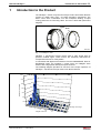


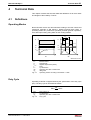
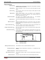
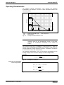
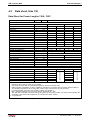
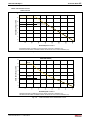
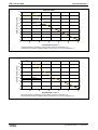
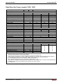
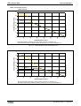
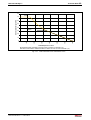
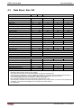
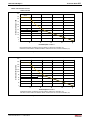
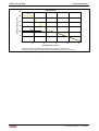
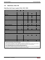
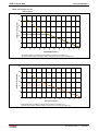
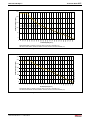
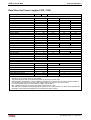
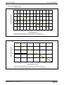
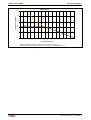
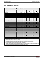
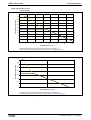
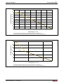
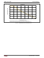
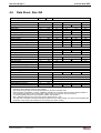
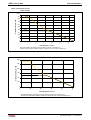
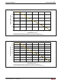
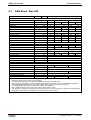
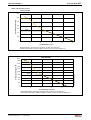
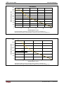
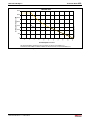
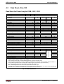
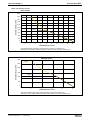
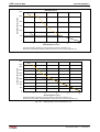
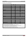
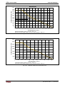
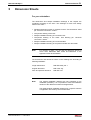
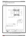
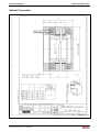
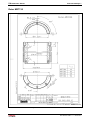
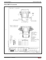
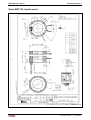
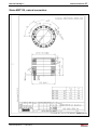
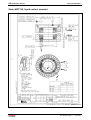
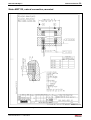
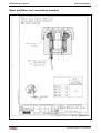
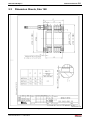
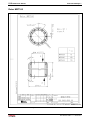
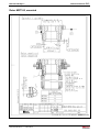
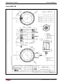
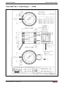
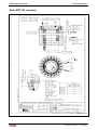
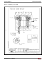
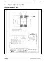
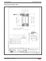
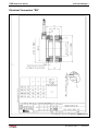
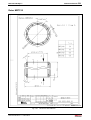
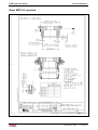
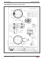
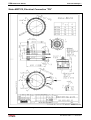
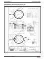
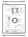
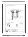
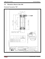
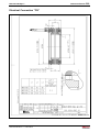
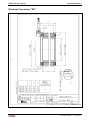
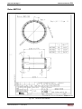
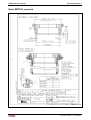
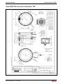
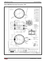
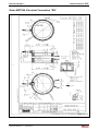
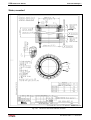
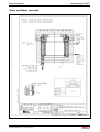
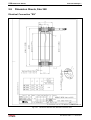
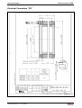
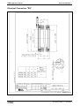
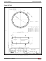
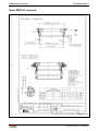
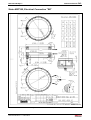
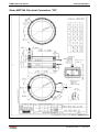
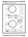
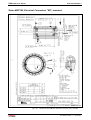
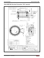
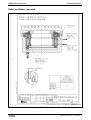
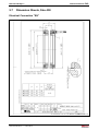
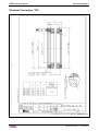
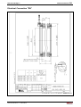
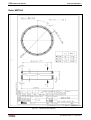
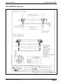
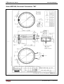
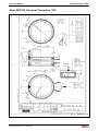
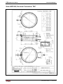
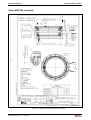
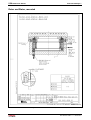
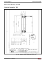
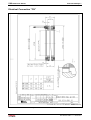
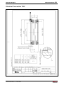
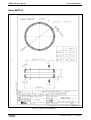
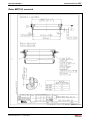
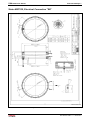
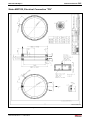
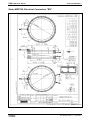
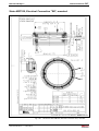
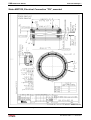
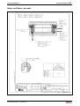

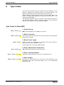
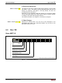
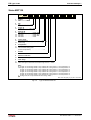
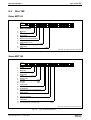
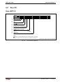
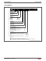
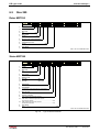
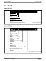
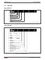
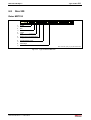
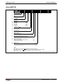
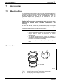
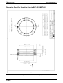
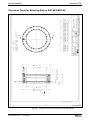
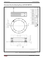
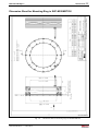
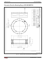
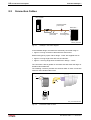
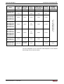
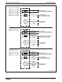
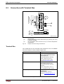
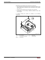
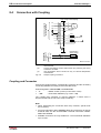
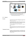
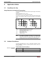
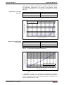
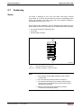
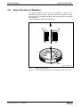
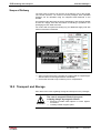
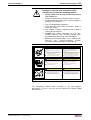
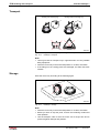
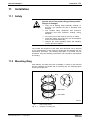
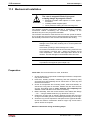
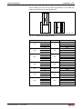
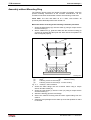
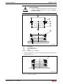
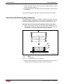
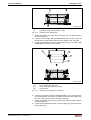
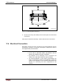

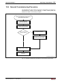
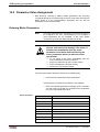
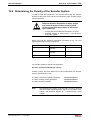
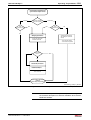
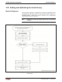
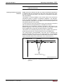

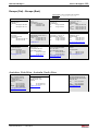
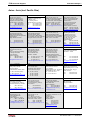
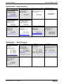
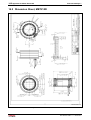
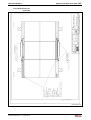
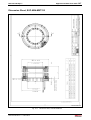

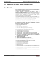
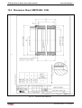
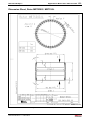

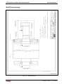
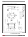
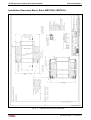
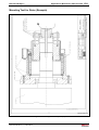
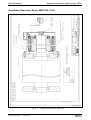


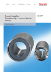


![[Download] azionamenti-hcs01](http://vs1.manualzilla.com/store/data/006141009_1-1242967de3765f3b826dc0b688197751-150x150.png)