1
Electric Drives
and Controls
Hydraulics
Linear Motion and
Assembly Technologies
Rexroth IndraDyn S
MSK Synchronous Motors
Project Planning Manual
Pneumatics
Service
R911296289
Edition 05
Bosch Rexroth AG | Electric Drives
and Controls
Title
Rexroth IndraDyn S | Project Planning Manual
Rexroth IndraDyn S
MSK Synchronous Motors
Type of Documentation
Document Typecode
Internal File Reference
Purpose of Documentation
Record of Revision
Copyright
Project Planning Manual
DOK-MOTOR*-MSK********-PR05-EN-P
RS-e376b79b0a6846ac00f6d325fdbe2ed7-1-en-US-6
This documentation…
●
explains the features of the product, operating conditions, conditions for
use and operating limits for MSK motors.
●
contains technical data regarding available MSK motors.
●
provides information regarding product selection, handling and operation
Edition
Release Date
Notes
DOK-MOTOR*-MSK********-PR01-EN-P
06/2004
First edition
DOK-MOTOR*-MSK********-PR02-EN-P
10/2004
Revision, amendment
DOK-MOTOR*-MSK********-PR03-EN-P
02/2005
Revision, amendment,
not printed
DOK-MOTOR*-MSK********-PR04-EN-P
06/2005
Revision, amendment
DOK-MOTOR*-MSK********-PR05-EN-P
03/2006
Revision, amendment
© 2006 Bosch Rexroth AG
Copying this document, giving it to others and the use or communication of the
contents therof without express authourity, are forbidden. Offenders are liable
for the payment of damages. All rights are reserved in the event of the grant of
a patent or the registration of a utility model or design (DIN 34-1).
Validity
Published by
The specified data is for product description purposes only and may not be
deemed to be guaranteed unless expressly confirmed in the contract. All rights
are reserved with respect to the content of this documentation and the availability of the product.
Bosch Rexroth AG
Bgm.-Dr.-Nebel-Str. 2 ■ 97816 Lohr a. Main, Germany
Tel. +49 (0)93 52 / 40-0 ■ Fax +49 (0)93 52 / 40-48 85
http://www.boschrexroth.com/
Dept. BRC/EDM2 (JW)
Note
This document has been printed on chlorine-free bleached paper.
Project Planning Manual | Rexroth IndraDyn S
Electric Drives | Bosch Rexroth AG
and Controls
I/V
Table of contents
Table of contents
Page
1
1.1
1.2
2
2.1
2.1.1
2.1.2
2.2
3
3.1
3.2
3.3
3.4
3.5
3.6
3.7
3.8
3.9
3.10
3.11
4
4.1
4.1.1
4.1.2
4.1.3
4.1.4
4.1.5
4.2
4.3
4.4
4.5
4.6
4.7
4.8
4.9
4.10
4.11
4.12
4.13
4.14
Introduction.................................................................................................................... 1
Introduction to the Product IndraDyn S................................................................................................... 1
About this Documentation....................................................................................................................... 2
Important Directions for Use .......................................................................................... 5
Appropriate Use ..................................................................................................................................... 5
Introduction.......................................................................................................................................... 5
Areas of Use and Application............................................................................................................... 5
Inappropriate Use .................................................................................................................................. 6
Safety Instructions for Electric Drives and Controls ....................................................... 7
Introduction............................................................................................................................................. 7
Explanation............................................................................................................................................. 7
General................................................................................................................................................... 7
Protection Against Contact with Electric Parts........................................................................................ 9
Protection Against Electric Shock by Protective Extra-Low Voltage...................................................... 10
Protection Against Dangerous Movements........................................................................................... 10
Protection Against Magnetic and Electromagnetic Fields During Operation and Mounting.................... 12
Protection Against Contact with Hot Parts............................................................................................ 12
Protection During Handling and Mounting............................................................................................. 12
Battery Safety....................................................................................................................................... 13
Protection Against Pressurized Systems.............................................................................................. 13
Technical Data............................................................................................................. 15
Definition of Parameters ...................................................................................................................... 15
60K and 100K Parameters................................................................................................................. 15
Operating Mode ................................................................................................................................ 15
Operating Time ................................................................................................................................. 16
Dimension Sheet Specifications........................................................................................................ 16
Example of a Characteristic Curve..................................................................................................... 18
MSK030B Technical Data..................................................................................................................... 19
MSK030C Technical Data..................................................................................................................... 21
MSK040B Technical Data..................................................................................................................... 23
MSK040C Technical Data..................................................................................................................... 25
MSK050B Technical Data..................................................................................................................... 27
MSK050C Technical Data..................................................................................................................... 30
MSK060B Technical Data..................................................................................................................... 33
MSK060C Technical Data..................................................................................................................... 36
MSK061C Technical Data..................................................................................................................... 39
MSK070C Technical Data..................................................................................................................... 41
MSK070D Technical Data..................................................................................................................... 45
MSK070E Technical Data..................................................................................................................... 49
MSK071D Technical Data..................................................................................................................... 53
II/V
Bosch Rexroth AG | Electric Drives
and Controls
Rexroth IndraDyn S | Project Planning Manual
Table of contents
Page
4.15
4.16
4.17
4.18
4.19
4.20
4.21
5
5.1
5.2
5.3
5.4
5.5
5.6
5.7
5.8
5.9
5.10
5.11
5.12
5.13
6
6.1
6.2
6.3
6.4
6.5
6.6
6.7
6.8
6.9
6.10
6.11
7
7.1
7.1.1
7.1.2
7.2
7.3
7.3.1
7.3.2
7.3.3
MSK071E Technical Data..................................................................................................................... 58
MSK076C Technical Data..................................................................................................................... 63
MSK100B Technical Data..................................................................................................................... 66
MSK100C Technical Data..................................................................................................................... 70
MSK100D Technical Data..................................................................................................................... 74
MSK101D Technical Data..................................................................................................................... 77
MSK101E Technical Data..................................................................................................................... 82
Specifications............................................................................................................... 87
Basic Data – Technical Design ............................................................................................................. 87
Size MSK030........................................................................................................................................ 88
Size MSK040........................................................................................................................................ 89
Size MSK050........................................................................................................................................ 90
Size MSK060........................................................................................................................................ 91
Size MSK061........................................................................................................................................ 92
Size MSK070........................................................................................................................................ 93
Size MSK071........................................................................................................................................ 94
Size MSK071 with Liquid Coolant......................................................................................................... 95
Size MSK076........................................................................................................................................ 96
Size MSK100........................................................................................................................................ 97
Size MSK101........................................................................................................................................ 98
Size MSK101 with Liquid Cooling......................................................................................................... 99
Type Codes................................................................................................................ 101
Description.......................................................................................................................................... 101
Size MSK030...................................................................................................................................... 105
Size MSK040...................................................................................................................................... 107
Size MSK050...................................................................................................................................... 109
Size MSK060...................................................................................................................................... 111
Size MSK061...................................................................................................................................... 113
Size MSK070...................................................................................................................................... 115
Size MSK071...................................................................................................................................... 117
Size MSK076...................................................................................................................................... 119
Size MSK100...................................................................................................................................... 121
Size MSK101...................................................................................................................................... 123
Accessories and Options........................................................................................... 125
Motor Encoder ................................................................................................................................... 125
General............................................................................................................................................ 125
Motor Encoder Technical Data........................................................................................................ 125
Holding Brakes................................................................................................................................... 126
Fan Units for MSK Motors................................................................................................................... 126
Technical Data................................................................................................................................. 126
Assignment...................................................................................................................................... 126
Electrical Connection, Adjust Motor Protection................................................................................ 127
Project Planning Manual | Rexroth IndraDyn S
Electric Drives | Bosch Rexroth AG
and Controls
III/V
Table of contents
Page
7.3.4
7.3.5
7.3.6
7.4
7.5
8
8.1
8.2
8.2.1
8.2.2
8.3
8.3.1
8.3.2
8.4
8.4.1
8.4.2
8.5
8.5.1
8.5.2
8.6
8.6.1
8.6.2
8.6.3
8.6.4
8.7
8.7.1
8.7.2
9
9.1
9.1.1
9.1.2
9.1.3
9.1.4
9.2
9.3
Ordering........................................................................................................................................... 127
Specifications .................................................................................................................................. 129
MSK060 fan unit axial................................................................................................................... 129
MSK070 fan unit axial................................................................................................................... 130
MSK071 fan unit axial................................................................................................................... 131
MSK100 fan unit axial................................................................................................................... 132
MSK101 fan unit axial................................................................................................................... 133
Assembly......................................................................................................................................... 134
Fan unit LEM-AB-116N................................................................................................................. 134
Fan unit LEM-AB-140N................................................................................................................. 135
Fan unit LEM-AB-192N................................................................................................................. 136
Gearbox ............................................................................................................................................. 136
Sealing Air Connection....................................................................................................................... 136
Connection Techniques............................................................................................. 141
General............................................................................................................................................... 141
Power Connector Size 1..................................................................................................................... 142
RLS1100 Flange Socket.................................................................................................................. 142
RLS1101 Power Connector ............................................................................................................ 143
Power Connector Size 1.5.................................................................................................................. 144
RLS1200 Flange Socket.................................................................................................................. 144
RLS1201 Power Connector ............................................................................................................ 145
Power Connector Size 2..................................................................................................................... 147
RLS1300 Flange Socket.................................................................................................................. 147
RLS1301 Power Connector ............................................................................................................ 148
Encoder connector.............................................................................................................................. 150
RGS1000 Flange Socket, RGS1003 Flange Socket........................................................................ 150
RGS1001 Power Connector............................................................................................................ 151
Connection Cable............................................................................................................................... 152
Dimensioning of Power Cables........................................................................................................ 152
Ready-Made Connection Cables..................................................................................................... 153
Cable Layout.................................................................................................................................... 153
Line Lengths.................................................................................................................................... 154
Motor Cooling System......................................................................................................................... 154
Connection Techniques Fan Units................................................................................................... 154
Connection Technique Liquid Cooling............................................................................................. 154
Operating Conditions and Application Notes.............................................................. 157
Ambient Conditions ............................................................................................................................ 157
Setup elevation and ambient temperature ...................................................................................... 157
Humidity / Temperature .................................................................................................................. 157
Vibration .......................................................................................................................................... 158
Shock .............................................................................................................................................. 158
Protection Class.................................................................................................................................. 159
Compatibility with Foreign Materials .................................................................................................. 160
IV/V
Bosch Rexroth AG | Electric Drives
and Controls
Rexroth IndraDyn S | Project Planning Manual
Table of contents
Page
9.4
9.5
9.6
9.6.1
9.6.2
9.6.3
9.7
9.7.1
9.7.2
9.7.3
9.8
9.9
9.9.1
9.9.2
9.9.3
9.10
9.10.1
9.10.2
9.10.3
9.11
9.11.1
9.11.2
9.11.3
9.12
9.12.1
9.12.2
9.12.3
10
10.1
10.1.1
10.1.2
10.1.3
10.2
10.2.1
10.2.2
10.3
10.4
10.5
Design and Installation Positions ....................................................................................................... 160
Housing Varnish ................................................................................................................................ 161
Output Shaft ....................................................................................................................................... 161
Smooth Shaft .................................................................................................................................. 161
Output Shaft with Key ..................................................................................................................... 162
Output Shaft with Shaft Sealing Ring .............................................................................................. 162
Bearing and Shaft Load ..................................................................................................................... 164
General............................................................................................................................................ 164
Radial Load, Axial Load .................................................................................................................. 164
Bearing Lifetime .............................................................................................................................. 165
Attachment of Drive Elements ............................................................................................................ 166
Holding Brakes .................................................................................................................................. 167
General............................................................................................................................................ 167
Dimension of Holding Brakes .......................................................................................................... 168
General......................................................................................................................................... 168
Safety Notes Holding Brakes ....................................................................................................... 169
Drive of Holding Brakes .................................................................................................................. 169
Acceptances and Authorizations......................................................................................................... 169
CE-Sign .......................................................................................................................................... 169
UR, cUR Listing .............................................................................................................................. 169
CCC (China Compulsory Certification)............................................................................................ 170
Motor Cooling System......................................................................................................................... 170
Natural Convection.......................................................................................................................... 170
Fan Units......................................................................................................................................... 170
Liquid cooling................................................................................................................................... 170
General......................................................................................................................................... 170
Operating pressure ...................................................................................................................... 171
Coolant ........................................................................................................................................ 172
Used Materials ............................................................................................................................. 173
Coolant inlet temperature ............................................................................................................. 173
Motor Temperature Overview............................................................................................................. 174
General............................................................................................................................................ 174
Temperature sensor ....................................................................................................................... 174
Temperature Model......................................................................................................................... 174
Handling, Transport and Storage............................................................................... 175
Supplied Condition.............................................................................................................................. 175
General............................................................................................................................................ 175
Inspection at the Factory.................................................................................................................. 175
Test on the Customer Side.............................................................................................................. 175
Identification and Checking of the Supplied Goods............................................................................. 175
Shipping documents and delivery note............................................................................................ 175
Name plate...................................................................................................................................... 176
Handling of the Equipment.................................................................................................................. 176
Transport of the Equipment ................................................................................................................ 177
Storage of the Equipment .................................................................................................................. 178
Project Planning Manual | Rexroth IndraDyn S
Electric Drives | Bosch Rexroth AG
and Controls
V/V
Table of contents
Page
11
11.1
11.2
11.3
11.3.1
11.3.2
11.3.3
11.4
11.4.1
11.4.2
11.4.3
12
12.1
12.2
12.3
12.4
12.4.1
12.4.2
12.4.3
12.4.4
12.4.5
12.5
12.6
12.7
13
13.1
14
14.1
14.2
14.3
14.4
Installation.................................................................................................................. 179
Safety.................................................................................................................................................. 179
Skilled Personnel................................................................................................................................ 179
Mechanical Mounting – Motor Assembly............................................................................................. 179
Mounting the Flange........................................................................................................................ 179
Preparation...................................................................................................................................... 180
Assembly......................................................................................................................................... 180
Electrical Connection – Motor Connection.......................................................................................... 180
General............................................................................................................................................ 180
Connecting the Plug........................................................................................................................ 181
Adjusting the Output Direction......................................................................................................... 181
Commissioning, Operation and Maintenance ............................................................ 183
Commissioning................................................................................................................................... 183
Operation............................................................................................................................................ 183
Deactivation........................................................................................................................................ 183
Maintenance....................................................................................................................................... 184
General............................................................................................................................................ 184
Cleaning.......................................................................................................................................... 184
Bearing............................................................................................................................................ 184
Connection Cable............................................................................................................................ 185
Holding Brakes ............................................................................................................................... 185
Troubleshooting.................................................................................................................................. 186
Dismantling......................................................................................................................................... 186
Waste Disposal................................................................................................................................... 186
Appendix.................................................................................................................... 189
List of Standards................................................................................................................................. 189
Service & Support...................................................................................................... 191
Helpdesk............................................................................................................................................. 191
Service Hotline.................................................................................................................................... 191
Internet................................................................................................................................................ 191
Helpful Information.............................................................................................................................. 191
Index.......................................................................................................................... 193
Bosch Rexroth AG | Electric Drives
and Controls
Rexroth IndraDyn S | Project Planning Manual
Project Planning Manual | Rexroth IndraDyn S
Electric Drives | Bosch Rexroth AG
and Controls
1/194
Introduction
1
Introduction
1.1
Introduction to the Product IndraDyn S
IndraDyn S servomotors set new standards. Many innovations in synchronous
servomotors combine past experiences and the most up-to-date motor technology to create a new standard.
IndraDyn S servomotors are characterized by
●
dynamics
●
a compact construction
●
a high torque density
●
an extremely high degree of precision due to new optical encoder systems
IndraDyn S motors are available in the following power spectrum:
Fig.1-1:
MSK power graduation
2/194
Bosch Rexroth AG | Electric Drives
and Controls
Rexroth IndraDyn S | Project Planning Manual
Introduction
1.2
About this Documentation
Document Structure
This documentation contains safety regulations, technical data and operating
instructions for IndraDyn S motors. The individual chapters can be subdivided
into the following focal points:
Section / Title
Contents
chapter 1 "Introduction" on page 1
General Information
chapter 2 "Important Directions for Use " on page 5
chapter 3 "Safety Instructions for Electric Drives and Controls " Safety
on page 7
chapter 4 "Technical Data" on page 15
chapter 5 "Specifications" on page 87
chapter 6 "Type Codes" on page 101
Product description
(for planners and
designers)
chapter 7 "Accessories and Options" on page 125
chapter 8 "Connection Techniques" on page 141
chapter 9 "Operating Conditions and Application Notes" on
page 157
chapter 10 "Handling, Transport and Storage" on page 175
chapter 11 "Installation" on page 179
chapter 12 "Commissioning, Operation and Maintenance " on
page 183
In Practice (for operating and maintenance personnel)
chapter 13 "Appendix" on page 189
chapter 14 "Service & Support" on page 191
General Information
Index
Fig.1-2:
Additional documentation
Document Structure
If required, you need additional documentation referring the used devices, to
project the drive-systems of the MSK motor unit. Rexroth provides all product
documentation on DVD in a PDF-format. You will not need all the documentation included on the DVD to project a system.
All documentation on the DVD are also available in a printed version. You can order the required product documentation via your
Rexroth sales office.
MNR
R911306531
1)
Fig.1-3:
Standards
Title / Designation
-Product documentation Electric Drives and Controls Version xx 1)
DOK-GENERL-DRIVE*CONTR-GNxx-D0-V04G7
1) The index (16, for example) identifies the version of the DVD.
Additional documentation on DVD
This documentation refers to German, European and international technical
standards. Documents and sheets on standards are subject to copyright protection and may not be passed on to third parties by Rexroth. If necessary,
please address the authorized sales outlets or, in Germany, directly to:
BEUTH Verlag GmbH
Project Planning Manual | Rexroth IndraDyn S
Electric Drives | Bosch Rexroth AG
and Controls
3/194
Introduction
Burggrafenstrasse 6
10787 Berlin, Germany
Phone +49-(0)30-26 01-22 60, Fax +49-(0)30-26 01-12 60
Internet: http://www.din.de/beuth
Email: [email protected]
Foreign systems
Documentation for external systems which are connected to Rexroth components are not included in the scope of delivery and must be ordered directly
from the particular manufacturers.
Feedback
Your experiences are an essential part of the process of improving both the
product and the documentation.
Please do not hesitate to inform us of any mistakes you detect in this documentation or of any modifications you might desire. We would appreciate your
feedback.
Please send your remarks to:
Bosch Rexroth AG
Dep. BRC/EDM2
Buergermeister-Dr.-Nebel-Strasse 2
97816 Lohr, Germany
Fax +49 (0) 93 52 / 40-43 80
Bosch Rexroth AG | Electric Drives
and Controls
Rexroth IndraDyn S | Project Planning Manual
Project Planning Manual | Rexroth IndraDyn S
Electric Drives | Bosch Rexroth AG
and Controls
5/194
Important Directions for Use
2
Important Directions for Use
2.1
Appropriate Use
2.1.1
Introduction
Rexroth products represent state-of-the-art developments and manufacturing.
They are tested prior to delivery to ensure operating safety and reliability.
Personal injury and property damage caused by inappropriate use of
the products!
WARNING
The products may only be used in the manner that is defined as appropriate. If
they are used in an inappropriate manner, then situations can develop that may
lead to property damage or injury to personnel.
Rexroth, as manufacturer, is not liable for any damages resulting
from inappropriate use. In such cases, the guarantee and the right
to payment of damages resulting from inappropriate use are forfeited. The user alone carries all responsibility of the risks.
Before using Rexroth products, make sure that all the pre-requisites for appropriate use of the products are satisfied:
2.1.2
●
Personnel that in any way, shape or form uses our products must first read
and understand the relevant safety instructions and be familiar with appropriate use.
●
If the product takes the form of hardware, then they must remain in their
original state, in other words, no structural changes are permitted. It is not
permitted to decompile software products or alter source codes.
●
Do not mount damaged or faulty products or use them in operation.
●
Make sure that the products have been installed in the manner described
in the relevant documentation.
Areas of Use and Application
Motors of the MSK line made by Rexroth are designed to be used as rotary
main and servo drives, as linear drives, or as kit motors. Typical applications
are:
●
Machine tools
●
Printing and paper processing machines
●
Packaging and foodstuff machines
●
Metal-forming machine tools
To ensure an application-specific use, the motors are available with differing
drive power and different interfaces.
Control and monitoring of motors may require additional sensors and actors.
MSK may only be used with the accessories and parts specified in
this document. If a component has not been specifically named,
then it may not be either mounted or connected. The same applies
to cables and lines.
Operation is only permitted in the specified configurations and combinations of components using the software and firmware as specified in the relevant function descriptions.
6/194
Bosch Rexroth AG | Electric Drives
and Controls
Rexroth IndraDyn S | Project Planning Manual
Important Directions for Use
Every connected drive controller has to be programmed before starting it up,
making it possible for the motor to execute the specific functions of an application.
MSK may only be operated under the assembly, installation and ambient conditions as described here (temperature, system of protection, humidity, EMC
requirements, etc.) and in the position specified.
2.2
Inappropriate Use
Using MSK outside of the above-referenced areas of application or under operating conditions other than described in the document and the technical data
specified is defined as "inappropriate use".
MSK may not be used if
●
they are subject to operating conditions that do not meet the above specified ambient conditions. This includes, for example, operation under water, in the case of extreme temperature fluctuations or extremely high
maximum temperatures or if
●
Rexroth has not specifically released them for that intended purpose.
Please note the specifications outlined in the general safety instructions!
Project Planning Manual | Rexroth IndraDyn S
Electric Drives | Bosch Rexroth AG
and Controls
7/194
Safety Instructions for Electric Drives and Controls
3
Safety Instructions for Electric Drives and Controls
3.1
Introduction
Read at first the following notes before startup procedure to avoid personal
injury and/or material damages! This safety notes are always to be observed.
Do not try to install this machine or take into commission before you haven`t
read all delivered documentations exactly. This safety instructions and all other
user notes must always been read before working with this machine. Should
you have no user notes for this machine, please contact your responsible sales
representative at Rexroth Indramat. Ask for prompt sending of this documentations to the responsible person to use this machine safely.
You have to pass this safety notes when you sell, lend out or otherwise pass
this machine.
Improper use of this equipment, failure to follow the attached safety instructions, or tampering with the product, including disabling or disconnection the safety device, may result in injury, severe electrical shock
or death and material damage!
WARNING
3.2
Observe the following instructions.
Explanation
The safety instructions describe the following degrees of hazard seriousness.
The degree of hazard seriousness informs about the consequences resulting
from non-compliance with the safety instructions:
Warning symbols with signal word
Hazard classification (according to ANSI Z 535)
Death or severe bodily injury will occur.
DANGER
Death or severe bodily injury may occur.
WARNING
Bodily injury or damage may occur.
CAUTION
Fig.3-1:
3.3
Danger classes (according to ANSI Z 535)
General
●
Bosch Rexroth AG is not liable for damages resulting from failure to observe the warnings provided in this documentation.
●
Read the operating, maintenance and safety instructions in your language
before commissioning the machine. If you find that you cannot completely
understand the documentation for your product, please ask your supplier
to clarify.
8/194
Bosch Rexroth AG | Electric Drives
and Controls
Rexroth IndraDyn S | Project Planning Manual
Safety Instructions for Electric Drives and Controls
●
Proper and correct transport, storage, assembly and installation, as well
as care in operation and maintenance, are prerequisites for optimal and
safe operation of this device.
●
Only assign trained and qualified persons to work with electrical installations:
●
Only persons who are trained and qualified for the use and operation of
the device may work on this device or within its proximity. The persons
are qualified if they have sufficient knowledge of the assembly, installation
and operation of the product, as well as an understanding of all warnings
and precautionary measures noted in these instructions.
●
Furthermore, they must be trained, instructed and qualified to switch electrical circuits and devices on and off in accordance with technical safety
regulations, to ground them and to mark them according to the requirements of safe work practices. They must have adequate safety equipment
and be trained in first aid.
●
Only use spare parts and accessories approved by the manufacturer.
●
Follow all safety regulations and requirements for the specific application
as practiced in the country of use.
●
The devices have been designed for installation in industrial machinery.
●
The ambient conditions given in the product documentation must be observed.
●
Only use safety-relevant applications that are clearly and explicitly approved in the Project Planning Manual. For example, the following operating conditions and fields of application are excluded: cranes, passenger
and freight elevators, equipments and vehicles for passenger transportation, medical applications, refinery, transport of dangerous goods, nuclear
applications, use in high-frequency sensitive areas, mining, food processing, control of protective decives (even in machines).
●
The information given in the documentation of the product with regard to
the use of the delivered components contains only examples of applications and suggestions.
The machine and installation manufacturer must
–
make sure that the delivered components are suited for his individual
application and check the information given in this documentation
with regard to the use of the components,
–
make sure that his application complies with the applicable safety
regulations and standards and carry out the required measures,
modifications and complements.
●
Commissioning of the delivered components is only permitted once it is
sure that the machine or installation in which they are installed complies
with the national regulations, safety specifications and standards of the
application.
●
Operation is only permitted if the national EMC regulations for the application are met.
For notes regarding an EMC-compatible installation, refer to the documentation "EMC at AC Drives and Controls".
The machine or installation manufacturer is responsible for compliance
with the limiting values as prescribed in the national regulations.
●
Technical data, connection and installation conditions are specified in the
product documentation and must be followed at all times.
Project Planning Manual | Rexroth IndraDyn S
Electric Drives | Bosch Rexroth AG
and Controls
9/194
Safety Instructions for Electric Drives and Controls
3.4
Protection Against Contact with Electric Parts
This section only concerns devices and drive components with voltages of more than 50 Volt.
Contact with parts conducting voltages above 50 volts can cause personal
danger and electric shock. When operating electrical equipment, it is unavoidable that some parts of the units conduct dangerous voltage.
High electrical voltage! Danger to life, electric shock and severe bodily
injury!
DANGER
⇒ Only those trained and qualified to work with or on electrical equipment are
permitted to operate, maintain and repair this equipment.
⇒ Follow general construction and safety regulations when working on electrical
power installations.
⇒ Before switching on the device, the equipment grounding conductor must
have been permanently connected to all electrical equipment in accordance
with the connection diagram.
⇒ Do not operate electrical equipment at any time, even for brief measurements
or tests, if the equipment grounding conductor is not permanently connected to
the mounting points of the components provided for this purpose.
⇒ Before working with electrical parts with voltage potentials higher than 50 V,
the device must be disconnected from the mains voltage or power supply unit.
Provide a safeguard to prevent reconnection.
For electrical drive and filter components, observe the following:
Wait 30 minutes after switching off power to allow capacitors to discharge before beginning to work. Measure the voltage on the capacitors before beginning
to work to make sure that the equipment is safe to touch.
⇒ Never touch the electrical connection points of a component while power is
turned on.
⇒ Install the covers and guards provided with the equipment properly before
switching the device on. Before switching the equipment on, cover and safeguard live parts safely to prevent contact with those parts.
⇒ A residual-current-operated circuit-breaker or r.c.d. cannot be used for electric drives! Indirect contact must be prevented by other means, for example, by
an overcurrent protective device according to the relevant standards.
⇒ Secure built-in devices from direct touching of electrical parts by providing
an external housing, for example a control cabinet.
European countries: according to EN 50178/1998, section 5.3.2.3.
USA: See National Electric Code (NEC), National Electrical Manufacturers Association (NEMA) as well as local building regulations. The user must always
keep all named articles.
For electrical drive and filter components, observe the following:
10/194
Bosch Rexroth AG | Electric Drives
and Controls
Rexroth IndraDyn S | Project Planning Manual
Safety Instructions for Electric Drives and Controls
High housing voltage and high leakage current! Risk of death or bodily
injury by electric shock!
DANGER
⇒ Before switching on, the housings of all electrical equipment and motors must
be connected or grounded with the equipment grounding conductor to the
grounding points. This is also applicable before short tests.
⇒ The equipment grounding conductor of the electrical equipment and the devices must be non-detachably and permanently connected to the power supply
unit at all times. The leakage current is greater than 3.5 mA.
⇒ Over the total length, use copper wire of a cross section of a minimum of
10 mm2 for this equipment grounding connection!
⇒ Before commissioning, also in trial runs, always attach the equipment grounding conductor or connect to the ground wire. Otherwise, high voltages may
occur at the housing causing electric shock.
3.5
Protection Against Electric Shock by Protective Extra-Low
Voltage
All connections and terminal connectors with a voltage of 5 to 50 Volt on Rexroth
Indramat products are protective extra-low voltages, which are performed safe
from touch according to the product standards
High electric voltage by incorrect connection! Risk of death or bodily
injury by electric shock!
WARNING
3.6
⇒ Connect only devices with connectors and terminal connectors with a voltage
of 0 to 50 volt, which have a protective extra-low voltage (PELV).
⇒ Connect only voltages and circuits, which have a safe disconnection to dangerous voltages. A safe disconnection can be done, for example, by isolating
transformers, safe optocouplers or operation from battery.
Protection Against Dangerous Movements
Dangerous movements can be caused by faulty control of connected motors.
Some common examples are:
●
improper or wrong wiring of cable connections
●
incorrect operation of the equipment components
●
wrong input of parameters before operation
●
malfunction of sensors, encoders and monitoring devices
●
defective components
●
software or firmware errors
These errors can occur immediately after equipment is switched on or even
after an unspecified time of trouble-free operation.
The monitoring in the drive components will normally be sufficient to avoid faulty
operation in the connected drives. Regarding personal safety, especially the
danger of bodily harm and/or material damage, this alone cannot be relied upon
to ensure complete safety. Until the integrated monitoring functions become
effective, it must be assumed in any case that faulty drive movements will occur.
The extent of faulty drive movements depends upon the type of control and the
state of operation.
Project Planning Manual | Rexroth IndraDyn S
Electric Drives | Bosch Rexroth AG
and Controls
11/194
Safety Instructions for Electric Drives and Controls
Dangerous movements! Danger to life, risk of injury, severe bodily harm
or material damage!
DANGER
⇒ For the above reasons, ensure personal safety by means of qualified and
tested higher-level monitoring devices or measures integrated in the installation.
They have to be provided for by the user according to the specific conditions
within the installation and a hazard and fault analysis. The safety regulations
applicable for the installation have to be taken into consideration. Unintended
machine motion or other malfunction is possible if safety devices are disabled,
bypassed or not activated.
To avoid accidents, bodily harm and/or material damage:
⇒ Keep free and clear of the machine’s range of motion and moving parts.
Possible measures to prevent people from accidentally entering the machine’s
range of motion:
●
use safety fences
●
use safety guards
●
use protective coverings
●
install light curtains or light barriers
⇒ Fences and coverings must be strong enough to resist maximum possible
momentum.
⇒ Mount the emergency stop switch in the immediate reach of the operator.
Verify that the emergency stop works before commissioning. Do not operate
the device if the emergency stop switch is not working.
⇒ Isolate the drive power connection by means of an emergency stop circuit or
use a safety related starting lockout to prevent unintentional start.
⇒ Make sure that the drives are brought to a safe standstill before accessing
or entering the danger zone.
⇒ Additionally secure vertical axes against falling or dropping after switching
off the motor power by, for example:
●
mechanically securing the vertical axes,
●
adding an external braking/arrester/clamping mechanism or
●
ensuring sufficient equilibration of the vertical axes.
The standard equipment motor brake or an external brake controlled by the
drive controller are not sufficient to guarantee personal safety!
⇒ Disconnect electrical power to the equipment using a master switch and secure the switch against reconnection for:
●
maintenance and repair work
●
cleaning of equipment
●
long periods of discontinued equipment use
⇒ Prevent the operation of high-frequency, remote control and radio equipment
near electronics circuits and supply leads. If the use of such devices cannot be
avoided, verify the system and the installation for possible malfunctions in all
possible positions of normal use before initial commissioning. If necessary,
perform a special electromagnetic compatibility (EMC) test on the installation.
12/194
Bosch Rexroth AG | Electric Drives
and Controls
Rexroth IndraDyn S | Project Planning Manual
Safety Instructions for Electric Drives and Controls
3.7
Protection Against Magnetic and Electromagnetic Fields During Operation and Mounting
Magnetic and electromagnetic fields generated by current-carrying conductors
and permanent magnets in motors represent a serious personal danger to
those with heart pacemakers, metal implants and hearing aids.
Health hazard for persons with heart pacemakers, metal implants and
hearing aids in proximity to electrical equipment!
WARNING
⇒ Persons with heart pacemakers and metal implants are not permitted to enter
following areas:
●
Areas in which electrical equipment and parts are mounted, being operated or commissioned.
●
Areas in which parts of motors with permanent magnets are being stored,
repaired or mounted.
⇒ If it is necessary for somebody with a pacemaker to enter such an area, a
doctor must be consulted prior to doing so. The noise immunity of present or
future implanted heart pacemakers differs greatly so that no general rules can
be given.
⇒ Those with metal implants or metal pieces, as well as with hearing aids, must
consult a doctor before they enter the areas described above. Otherwise health
hazards may occur.
3.8
Protection Against Contact with Hot Parts
Danger of burning via hot surfaces with temperatures over 100°C!
WARNING
⇒ Touch the motor only after cooling! A cooling time up to 140 minutes can be
necessary! The stated thermical time constant in the technical data is a measure for the necessary cooling
⇒ Do not work on hot surfaces.
⇒ Use safety gloves.
Hot surfaces on device housing! Danger of injury! Danger of burns!
⇒ Do not touch the housing surface near a hot heat source! Danger of burns!
CAUTION
⇒ After switching devices off, wait 10 minutes to allow them to cool down before
touching them.
⇒ Touching hot parts of the machine, like the housing which contains the heat
sink and resistances, could lead to combustions!
3.9
Protection During Handling and Mounting
In unfavorable conditions, handling and mounting certain parts and components in an improper way can cause injuries.
Project Planning Manual | Rexroth IndraDyn S
Electric Drives | Bosch Rexroth AG
and Controls
13/194
Safety Instructions for Electric Drives and Controls
Risk of injury by improper handling! Bodily injury by bruising, shearing,
cutting, hitting!
CAUTION
⇒ Observe the general construction and safety regulations on handling and
mounting.
Use suitable devices for mounting and transport.
⇒ Avoid jamming and bruising by appropriate measures.
⇒ Always use suitable tools. Use special tools if specified.
⇒ Use lifting equipment and tools in the correct manner.
⇒ If necessary, use suitable protective equipment (for example safety goggles,
safety shoes, safety gloves).
⇒ Do not stand under hanging loads.
⇒ Immediately clean up any spilled liquids because of the danger of skidding.
3.10
Battery Safety
Batteries consist of active chemicals enclosed in a solid housing. Therefore,
improper handling can cause injury or material damage.
Risk of injury by improper handling!
CAUTION
⇒ Do not attempt to reactivate low batteries by heating or other methods (risk
of explosion and cauterization).
⇒ Do not recharge the batteries as this may cause leakage or explosion.
⇒ Do not throw batteries into open flames.
⇒ Do not dismantle batteries.
⇒ Do not damage electrical parts which are mounted into the devices.
Environmental protection and disposal! The batteries contained in
the product are considered dangerous goods during land, air, and
sea transport (risk of explosion) in the sense of the legal regulations.
Dispose of used batteries separate from other waste. Observe the
local regulations in the country of assembly.
3.11
Protection Against Pressurized Systems
According to the information given in the Project Planning Manuals, some IndraDyn motors, as well as drive controllers, can be partially supplied with
externally fed, pressurized media, such as compressed air, hydraulics oil, cooling liquids and cooling lubricating agents. Improper handling of the external
supply systems, supply lines or connections can cause injuries or material
damage.
Risk of injury by improper handling of pressurized lines!
⇒ Do not attempt to disconnect, open or cut pressurized lines (risk of explosion).
CAUTION
⇒ Observe the respective manufacturer's operating instructions.
⇒ Before dismounting lines, relieve pressure and empty medium.
⇒ Use suitable protective equipment (for example safety goggles, safety shoes,
safety gloves).
⇒ Immediately clean up any spilled liquids from the floor.
14/194
Bosch Rexroth AG | Electric Drives
and Controls
Rexroth IndraDyn S | Project Planning Manual
Safety Instructions for Electric Drives and Controls
Environmental protection and disposal! The agents used to operate
the product might not be economically friendly. Dispose of ecologically harmful agents separately from other waste. Observe the local
regulations in the country of assembly.
Project Planning Manual | Rexroth IndraDyn S
Electric Drives | Bosch Rexroth AG
and Controls
15/194
Technical Data
4
Technical Data
4.1
Definition of Parameters
4.1.1
60K and 100K Parameters
The speed-torque curves and the technical data are specified for two different
temperature models.
●
60K temperature stroke on the housing and
●
100K temperature stroke on the winding
When selecting the technical data, observe the temperatures specified! The appropriate parameters are identified by 100K or 60K.
Setup and measurement of the 60K
characteristic curve
Setup and measurement of the
100K characteristic curve
The motor data and characteristic curves for IndraDyn S motors are determined
under the following conditions:
●
Environmental temperature approx. 40°C
●
Insulated structure (aluminum flange)
●
Permissible temperature increase on the housing ΔT = 60K
●
In the case of motors with the optional holding brake, the data are always
specified for motors with a holding brake.
●
Motors with radial shaft sealing ring
The motor data and characteristic curves for IndraDyn S motors are determined
under the following conditions:
●
Environmental temperature approx. 40°C
●
Structure not insulated (attachment to steel flange, LxWxH = 450x30x350
or 120x40x100)
●
Permissible temperature increase on the winding ΔT = 100K
●
In the case of motors with the optional holding brake, the data are always
specified for motors with a holding brake.
●
Motors with radial shaft sealing ring
The machine accuracy can be negatively affected by an increased
linear expansion during 100K operation. We recommend using 60K
data when projecting systems.
4.1.2
Operating Mode
IndraDyn S motors are documented according to the inspection criteria and
measurement procedures of EN 60034-1. The specified characteristic curves
correspond to operating modes S1 or S3.
16/194
Bosch Rexroth AG | Electric Drives
and Controls
Rexroth IndraDyn S | Project Planning Manual
Technical Data
P
PV
Θ
Θmax
t
TC
ΔtP
ΔtV
Fig.4-1:
4.1.3
Load
Electric losses
Temperature
Highest temperature (motor housing)
Time
Cycle time
Operating time with constant load
Idle time
Operating modes according to EN 60034-1:1998
Operating Time
Operating mode S3 is supplemented by specification of the ON time (ED) in %.
The operating time is calculated as follows:
ED
ΔtP
Fig.4-2:
Cyclic duration factor in %
Operating time with constant load
Cyclic duration factor
The values specified in the documentation have been determined on the basis
of the following parameters:
Cycle duration: 10 min
Cyclic duration factor (ED): 25%
4.1.4
Dimension Sheet Specifications
Standstill continuous torque
Continuous stand-still current
The permanent shaft load on the motor output shaft at speed n≈0. The different
operating modes are indicated by the following indices:
M0_60
Continuous torque at standstill, 60K
M0_100
Continuous torque at standstill, 100K
M0_S
Standstill continuous torque surface
M0_L
Continuous torque at standstill, liquid
For the continuous torque at standstill M0 necessary phase current (effective
value) of the motor at a speed of n≈0. The various operating modes are indicated by the following indices.
I0_60(eff)
Continuous current at standstill, 60K
I0_100(eff)
Continuous current at standstill, 100K
Project Planning Manual | Rexroth IndraDyn S
Electric Drives | Bosch Rexroth AG
and Controls
17/194
Technical Data
I0_S(eff)
Standstill continuous torque surface
Maximum torque
I0_L(eff)
Mmax
Peak current
Imax(eff)
Continuous current at standstill, liquid
The maximum torque that can be output for approx. 400 ms at
a maximum current of Imax (guaranteed value which, owing to
production tolerances, may be up to 20% higher). The achievable maximum torque depends on the drive controller used.
Only the specified maximum torque in the selection lists is
binding.
Maximum short-term branch current (root-mean-square value)
of the motor permitted without damaging the permanent magnetic circuit of the motor.
Ratio of the torque to the motor phase current (root-meansquare value) at a motor temperature of 20°C. Unit Nm/A. Valid
up to approx. i = 2x I0_60(eff) .
Root-mean-square value of the induced motor voltage at a
motor temperature of 20°C and 1000 revolutions per minute.
Unit: V/1000min-1.
Resistance measured between two winding ends in ohms (Ω).
Inductivity measured between two winding ends in mH.
Capacity of short-circuited power connections U, V, W against
the motor housing.
Number of pole pairs of the motor.
Moment of inertia of the rotor without the optional holding
brake.
Maximum permissible speed of the motor. Limiting factors can
have mechanical (centrifugal forces, bearing stress) or electrical (DC link voltage) causes.
Motor mass without the holding brake option, given in kg.
Airborne noise emitted, in dB(A).
Torque constant at 20° C
KM_N
Constant voltage at 20°C
KEMK_1000
Winding resistance at 20°C
Winding inductivity
Discharge capacity
R12
L12
Cab
Number of pole pairs
Moment of inerta of rotor
p
Jrot
Maximum torque
Mass
Sound pressure level
nmax
m
LP
18/194
Bosch Rexroth AG | Electric Drives
and Controls
Rexroth IndraDyn S | Project Planning Manual
Technical Data
4.1.5
Example of a Characteristic Curve
S1 (60K)
S1 (100K)
S1 (surface)
S3 (25% ED)
①-④
①
②
③
④
Fig.4-3:
Continuous operation curve of the motor (according to EN 60034-1;
1998), natural convection
Continuous operation curve of the motor (according to EN 60034-1;
1998), natural convection
Continuous operation curve S1 of the motor (according to EN 60034-1;
1998), surface cooling.
Intermittent service characteristic curve at 25% operating rate of the
motor (according to EN 60034-1; 1998) and max. cycle time of 10 min.
Characteristic voltage limit curves When a speed at the safe commutation limit is reached, the voltage limit curve limits the available maximum
torque Mmax. The maximum motor speed is determined by the DC link
voltage used. There are separate characteristic curves for the various
drive controllers in connection with the power supply unit and the supply
voltage used.
Mmax for IndraDrive, controlled feed, 3 x AC 400V
Mmax for IndraDrive, uncontrolled feed, 3 x AC 480V
Mmax for IndraDrive, uncontrolled feed, 3 x AC 440V
Mmax for IndraDrive, uncontrolled feed, 3 x AC 400V
Example of a motor characteristic curve
Project Planning Manual | Rexroth IndraDyn S
Electric Drives | Bosch Rexroth AG
and Controls
19/194
Technical Data
4.2
MSK030B Technical Data
Description
Symbol
Unit
MSK030B-0900-NN
Continuous torque at standstill, 60K
M0_60
Nm
0,4
Continuous current at standstill, 60K
I0_60(eff)
A
1,5
Continuous torque at standstill,
100K
M0_100
Nm
0,4
Continuous current at standstill,
100K
I0_100(eff)
A
1,7
Maximum torque
Mmax
Nm
1,8
Maximum current
Imax(eff)
A
6,8
KM_N
Nm/A
0,29
V/min-1
17,9
Torque constant at 20°C
Constant voltage at 20°C
KEMK_100
0
Winding resistance at 20°C
R12
Ohm
7,20
Winding inductivity
L12
mH
8,100
Leakage capacitance of the component
Cab
nF
0,7
p
-
3
Moment of inertia of rotor without
brake1)
Jrot
kg*m2
0,00001
Thermal time constant
Tth
min
19,0
nmax
min-1
9000
Sound pressure level
LP
dB[A]
<75
Ambient temperature during operation
Tum
°C
0 ... 40
Degree of protection
-
IP65
Insulation class EN 60034-1
-
F
Number of pole pairs
Maximum speed
1)
Fig.4-4:
Description
Specified without brake. If necessary, add the moment of inertia brake.
Technical data
Symbol
Unit
BREMSE-231389
holding torque
M4
Nm
1,0
rated voltage ±10%
UN
V
24
rated currend
IN
A
0,40
connection time
t1
ms
3
disconnection time
t2
ms
4
moment of inertia brake
Jrot
kg*m2
0,000007
mass brake
MBr
kg
0,2
Fig.4-5:
MSK030: Holding brake - Technical data (optional)
20/194
Bosch Rexroth AG | Electric Drives
and Controls
Rexroth IndraDyn S | Project Planning Manual
Technical Data
Speed-torque characteristic
①
②
③
④
Fig.4-6:
Shaft load
Mmax for IndraDrive, controlled feed, 3x AC 400V
Mmax for IndraDrive, uncontrolled feed, 3x AC 480V
Mmax for IndraDrive, uncontrolled feed, 3x AC 440V
Mmax for IndraDrive, uncontrolled feed, 3x AC 400V
Speed-torque characteristic of MSK030B-0900
Diagram for determining the maximum permissible radial force Fradial .
Fig.4-7:
permissible radial force of MSK030 - Motors (shaft and bearing load)
The maximum permissible axial force Faxial is 50 N .
For additional information about permissible radial and axial forces, see chapter
9.7 "Bearing and Shaft Load " on page 164.
Project Planning Manual | Rexroth IndraDyn S
Electric Drives | Bosch Rexroth AG
and Controls
21/194
Technical Data
4.3
MSK030C Technical Data
Description
Symbol
Unit
MSK030C-0900-NN
Continuous torque at standstill, 60K
M0_60
Nm
0,8
Continuous current at standstill, 60K
I0_60(eff)
A
1,5
Continuous torque at standstill,
100K
M0_100
Nm
0,9
Continuous current at standstill,
100K
I0_100(eff)
A
1,7
Maximum torque
Mmax
Nm
4,0
Maximum current
Imax(eff)
A
6,8
KM_N
Nm/A
0,58
V/min-1
35,6
Torque constant at 20°C
Constant voltage at 20°C
KEMK_100
0
Winding resistance at 20°C
R12
Ohm
9,80
Winding inductivity
L12
mH
14,100
Leakage capacitance of the component
Cab
nF
1,3
p
-
3
Moment of inertia of rotor without
brake1)
Jrot
kg*m2
0,00003
Thermal time constant
Tth
min
15,0
nmax
min-1
9000
Sound pressure level
LP
dB[A]
<75
Ambient temperature during operation
Tum
°C
0 ... 40
Degree of protection
-
IP65
Insulation class EN 60034-1
-
F
Number of pole pairs
Maximum speed
1)
Fig.4-8:
Description
Specified without brake. If necessary, add the moment of inertia brake.
Technical data
Symbol
Unit
BREMSE-231389
Holding torque
M4
Nm
1,0
Rated voltage ±10%
UN
V
24
Rated currend
IN
A
0,40
Connection time
t1
ms
3
Disconnection time
t2
ms
4
Moment of inertia brake
Jrot
kg*m2
0,000007
Mass brake
MBr
kg
0,2
Fig.4-9:
MSK030: Holding brake - Technical data (optional)
22/194
Bosch Rexroth AG | Electric Drives
and Controls
Rexroth IndraDyn S | Project Planning Manual
Technical Data
Speed-torque characteristic
①
②
③
④
Fig.4-10:
Shaft load
Mmax for IndraDrive, controlled feed, 3x AC 400V
Mmax for IndraDrive, uncontrolled feed, 3x AC 480V
Mmax for IndraDrive, uncontrolled feed, 3x AC 440V
Mmax for IndraDrive, uncontrolled feed, 3x AC 400V
Speed-torque characteristic of MSK030C-0900
Diagram for determining the maximum permissible radial force Fradial .
Fig.4-11:
permissible radial force of MSK030 - Motors (shaft and bearing load)
The maximum permissible axial force Faxial is 50 N .
For additional information about permissible radial and axial forces, see chapter
9.7 "Bearing and Shaft Load " on page 164.
Project Planning Manual | Rexroth IndraDyn S
Electric Drives | Bosch Rexroth AG
and Controls
23/194
Technical Data
4.4
MSK040B Technical Data
Description
Symbol
Unit
MSK040B-0600-NN
Continuous torque at standstill, 60K
M0_60
Nm
1,7
Continuous current at standstill, 60K
I0_60(eff)
A
2,0
Continuous torque at standstill,
100K
M0_100
Nm
---
Continuous current at standstill,
100K
I0_100(eff)
A
---
Maximum torque
Mmax
Nm
5,1
Maximum current
Imax(eff)
A
8,0
KM_N
Nm/A
0,95
V/min-1
58,5
Torque constant at 20°C
Constant voltage at 20°C
KEMK_100
0
Winding resistance at 20°C
R12
Ohm
7,90
Winding inductivity
L12
mH
36,000
Leakage capacitance of the component
Cab
nF
1,5
p
-
4
Moment of inertia of rotor without
brake1)
Jrot
kg*m2
0,00010
Thermal time constant
Tth
min
13,0
nmax
min-1
7500
Sound pressure level
LP
dB[A]
<75
Ambient temperature during operation
Tum
°C
0 ... 40
Degree of protection
-
IP65
Insulation class EN 60034-1
-
F
Number of pole pairs
Maximum speed
1)
Fig.4-12:
Description
Specified without brake. If necessary, add the moment of inertia brake.
Technical Data
Symbol
Unit
BREMSE-305590
Holding torque
M4
Nm
4,0
Rated voltage ±10%
UN
V
24
Rated currend
IN
A
0,50
Connection time
t1
ms
35
Disconnection time
t2
ms
25
Moment of inertia brake
Jrot
kg*m2
0,000023
Mass brake
MBr
kg
0,3
Fig.4-13:
MSK040: Holding brake - Technical data (optional)
24/194
Bosch Rexroth AG | Electric Drives
and Controls
Rexroth IndraDyn S | Project Planning Manual
Technical Data
Speed-torque characteristics
①
②
③
④
Fig.4-14:
Shaft load
Mmax for IndraDrive, controlled feed, 3x AC 400V
Mmax for IndraDrive, uncontrolled feed, 3x AC 480V
Mmax for IndraDrive, uncontrolled feed, 3x AC 440V
Mmax for IndraDrive, uncontrolled feed, 3x AC 400V
Speed-torque characteristic of MSK040B-0600
Diagram for determining the maximum permissible radial force Fradial .
Fig.4-15:
permissible radial force of MSK040 - Motors (shaft and bearing load)
The maximum permissible axial force Faxial is 200 N .
For additional information about permissible radial and axial forces, see chapter
9.7 "Bearing and Shaft Load " on page 164.
Project Planning Manual | Rexroth IndraDyn S
Electric Drives | Bosch Rexroth AG
and Controls
25/194
Technical Data
4.5
MSK040C Technical Data
Description
Symbol
Unit
MSK040C-0600-NN
M0_60
Nm
2,7
continuous current at standstill,
60K
I0_60(eff)
A
3,1
continuous torque at standstill,
100K
M0_100
Nm
3,1
continuous current at standstill,
100K
I0_100(eff)
A
---
maximum torque
Mmax
Nm
8,1
maximum current
Imax(eff)
A
12,4
torque constant at 20°C
KM_N
Nm/A
0,95
constant voltage at 20°C
KEMK_1000
V/min-1
58,2
winding resistance at 20°C
R12
Ohm
3,90
winding inductivity
L12
mH
21,300
leakage capacitance of the component
Cab
nF
2,0
p
-
4
moment of inertia of rotor without
brake1)
Jrot
kg*m2
0,00014
thermal time constant
Tth
min
16,0
nmax
min-1
7500
sound pressure level
LP
dB[A]
<75
ambient temperature during operation
Tum
°C
0 ... 40
degree of protection
-
IP65
insulation class EN 60034-1
-
F
continuous torque at standstill, 60K
number of pole pairs
maximum speed
1)
Fig.4-16:
Description
specified without brake. If necessary, add the moment of inertia brake.
MSK - Technical Data (natural cooling)
Symbol
Unit
BREMSE-305590
holding torque
M4
Nm
4,0
rated voltage ±10%
UN
V
24
rated currend
IN
A
0,50
connection time
t1
ms
35
disconnection time
t2
ms
25
moment of inertia brake
Jrot
kg*m2
0,000023
mass brake
MBr
kg
0,3
Fig.4-17:
MSK040: Holding brake - Technical data (optional)
26/194
Bosch Rexroth AG | Electric Drives
and Controls
Rexroth IndraDyn S | Project Planning Manual
Technical Data
Speed-torque characteristics
①
②
③
④
Fig.4-18:
Shaft load
Mmax for IndraDrive, controlled feed, 3x AC 400V
Mmax for IndraDrive, uncontrolled feed, 3x AC 480V
Mmax for IndraDrive, uncontrolled feed, 3x AC 440V
Mmax for IndraDrive, uncontrolled feed, 3x AC 400V
Speed-torque characteristic of MSK040C-0600
Diagram for determining the maximum permissible radial force Fradial .
Fig.4-19:
permissible radial force of MSK040 - Motors (shaft and bearing load)
The maximum permissible axial force Faxial is 200 N .
For additional information about permissible radial and axial forces, see chapter
9.7 "Bearing and Shaft Load " on page 164.
Project Planning Manual | Rexroth IndraDyn S
Electric Drives | Bosch Rexroth AG
and Controls
27/194
Technical Data
4.6
MSK050B Technical Data
Description
Symbol
Unit
M0_60
Nm
continuous current at standstill,
60K
I0_60(eff)
A
continuous torque at standstill,
100K
M0_100
Nm
continuous current at standstill,
100K
I0_100(eff)
A
maximum torque
Mmax
Nm
maximum current
Imax(eff)
A
7,2
14,8
torque constant at 20°C
KM_N
Nm/A
1,80
0,90
constant voltage at 20°C
KEMK_1000
V/min-1
111,0
55,0
winding resistance at 20°C
R12
Ohm
13,10
3,30
winding inductivity
L12
mH
76,400
19,900
leakage capacitance of the component
Cab
nF
2,1
p
-
4
moment of inertia of rotor without
brake1)
Jrot
kg*m2
0,00028
thermal time constant
Tth
min
8,0
nmax
min-1
sound pressure level
LP
dB[A]
<75
ambient temperature during operation
Tum
°C
0 ... 40
degree of protection
-
IP65
insulation class EN 60034-1
-
F
continuous torque at standstill, 60K
number of pole pairs
maximum speed
1)
Fig.4-20:
Description
MSK050B-0300-NN
MSK050B-0600-NN
3,0
1,8
3,7
3,4
---
4,2
9,0
4300
6000
specified without brake. If necessary, add the moment of inertia brake.
MSK - Technical Data (natural cooling)
Symbol
Unit
BREMSE-298905
holding torque
M4
Nm
5,0
rated voltage ±10%
UN
V
24
rated currend
IN
A
0,65
connection time
t1
ms
13
disconnection time
t2
ms
43
moment of inertia brake
Jrot
kg*m2
0,000107
mass brake
MBr
kg
0,7
Fig.4-21:
MSK050: Holding brake - Technical data (optional)
28/194
Bosch Rexroth AG | Electric Drives
and Controls
Rexroth IndraDyn S | Project Planning Manual
Technical Data
Speed-torque characteristic
①
②
③
④
Fig.4-22:
Mmax for IndraDrive, controlled feed, 3x AC 400V
Mmax for IndraDrive, uncontrolled feed, 3x AC 480V
Mmax for IndraDrive, uncontrolled feed, 3x AC 440V
Mmax for IndraDrive, uncontrolled feed, 3x AC 400V
Speed-torque characteristic of MSK050B-0300
①
②
③
④
Fig.4-23:
Mmax for IndraDrive, controlled feed, 3x AC 400V
Mmax for IndraDrive, uncontrolled feed, 3x AC 480V
Mmax for IndraDrive, uncontrolled feed, 3x AC 440V
Mmax for IndraDrive, uncontrolled feed, 3x AC 400V
Speed-torque characteristic of MSK050B-0600
Project Planning Manual | Rexroth IndraDyn S
Electric Drives | Bosch Rexroth AG
and Controls
29/194
Technical Data
Shaft load
Diagram for determining the maximum permissible radial force Fradial .
Fig.4-24:
permissible radial force of MSK050 - Motors (shaft and bearing load)
The maximum permissible axial force Faxial is 300 N .
For additional information about permissible radial and axial forces, see chapter
9.7 "Bearing and Shaft Load " on page 164.
30/194
Bosch Rexroth AG | Electric Drives
and Controls
Rexroth IndraDyn S | Project Planning Manual
Technical Data
4.7
MSK050C Technical Data
Description
Symbol
Unit
Continuous torque at standstill, 60K
M0_60
Nm
Continuous current at standstill, 60K
I0_60(eff)
A
Continuous torque at standstill,
100K
M0_100
Nm
Continuous current at standstill,
100K
I0_100(eff)
A
Maximum torque
Mmax
Nm
Maximum current
Imax(eff)
A
12,4
24,8
KM_N
Nm/A
1,77
0,89
V/min-1
109,0
55,0
Torque constant at 20°C
Constant voltage at 20°C
KEMK_100
0
MSK050C-0300-NN
MSK050C-0600-NN
5,0
3,1
6,2
5,5
---
6,8
15,0
Winding resistance at 20°C
R12
Ohm
6,60
1,70
Winding inductivity
L12
mH
46,100
11,000
Leakage capacitance of the component
Cab
nF
2,6
p
-
4
Moment of inertia of rotor without
brake1)
Jrot
kg*m2
0,00033
Thermal time constant
Tth
min
14,0
nmax
min-1
Sound pressure level
LP
dB[A]
<75
Ambient temperature during operation
Tum
°C
0 ... 40
Degree of protection
-
IP65
Insulation class EN 60034-1
-
F
Number of pole pairs
Maximum speed
1)
Fig.4-25:
Description
4700
6000
Specified without brake. If necessary, add the moment of inertia brake.
MSK - Technical Data (natural cooling)
Symbol
Unit
BREMSE-298905
Holding torque
M4
Nm
5,0
Rated voltage ±10%
UN
V
24
Rated currend
IN
A
0,65
Connection time
t1
ms
13
Disconnection time
t2
ms
43
Moment of inertia brake
Jrot
kg*m2
0,000107
Mass brake
MBr
kg
0,7
Fig.4-26:
MSK050: Holding brake - Technical data (optional)
Project Planning Manual | Rexroth IndraDyn S
Electric Drives | Bosch Rexroth AG
and Controls
31/194
Technical Data
Speed-torque characteristic
①
②
③
④
Fig.4-27:
Mmax for IndraDrive, controlled feed, 3x AC 400V
Mmax for IndraDrive, uncontrolled feed, 3x AC 480V
Mmax for IndraDrive, uncontrolled feed, 3x AC 440V
Mmax for IndraDrive, uncontrolled feed, 3x AC 400V
Speed-torque characteristic of MSK050C-0300
①
②
③
④
Fig.4-28:
Mmax for IndraDrive, controlled feed, 3x AC 400V
Mmax for IndraDrive, uncontrolled feed, 3x AC 480V
Mmax for IndraDrive, uncontrolled feed, 3x AC 440V
Mmax for IndraDrive, uncontrolled feed, 3x AC 400V
Speed-torque characteristic of MSK050C-0600
32/194
Bosch Rexroth AG | Electric Drives
and Controls
Rexroth IndraDyn S | Project Planning Manual
Technical Data
Shaft load
Diagram for determining the maximum permissible radial force Fradial .
Fig.4-29:
permissible radial force of MSK050 - Motors (shaft and bearing load)
The maximum permissible axial force Faxial is 300 N .
For additional information about permissible radial and axial forces, see chapter
9.7 "Bearing and Shaft Load " on page 164.
Project Planning Manual | Rexroth IndraDyn S
Electric Drives | Bosch Rexroth AG
and Controls
33/194
Technical Data
4.8
MSK060B Technical Data
Description
Symbol
Unit
Continuous torque at standstill, 60K
M0_60
Nm
Continuous current at standstill, 60K
I0_60(eff)
A
Continuous torque at standstill,
100K
M0_100
Nm
---
Continuous current at standstill,
100K
I0_100(eff)
A
---
Maximum torque
Mmax
Nm
15,0
Maximum current
Imax(eff)
A
12,0
24,4
KM_N
Nm/A
1,85
0,90
V/min-1
113,5
55,2
Torque constant at 20°C
Constant voltage at 20°C
KEMK_100
0
MSK060B-0300-NN
MSK060B-0600-NN
5,0
3,0
6,1
Winding resistance at 20°C
R12
Ohm
7,30
1,85
Winding inductivity
L12
mH
73,000
18,000
Leakage capacitance of the component
Cab
nF
2,1
p
-
4
Moment of inertia of rotor without
brake1)
Jrot
kg*m2
0,00048
Thermal time constant
Tth
min
16,0
nmax
min-1
Sound pressure level
LP
dB[A]
<75
Ambient temperature during operation
Tum
°C
0 ... 40
Degree of protection
-
IP65
Insulation class EN 60034-1
-
F
Number of pole pairs
Maximum speed
1)
Fig.4-30:
Description
4800
6000
Specified without brake. If necessary, add the moment of inertia brake.
MSK - Technical Data (natural cooling)
Symbol
Unit
BREMSE-299026
Holding torque
M4
Nm
10,0
Rated voltage ±10%
UN
V
24
Rated currend
IN
A
0,75
Connection time
t1
ms
25
Disconnection time
t2
ms
40
Moment of inertia brake
Jrot
kg*m2
0,000059
Mass brake
MBr
kg
0,4
Fig.4-31:
MSK060: Holding brake - Technical data (optional)
34/194
Bosch Rexroth AG | Electric Drives
and Controls
Rexroth IndraDyn S | Project Planning Manual
Technical Data
Speed-torque characteristics
①
②
③
④
Fig.4-32:
Mmax for IndraDrive, controlled feed, 3x AC 400V
Mmax for IndraDrive, uncontrolled feed, 3x AC 480V
Mmax for IndraDrive, uncontrolled feed, 3x AC 440V
Mmax for IndraDrive, uncontrolled feed, 3x AC 400V
Speed-torque characteristic of MSK060B-0300
①
②
③
④
Fig.4-33:
Mmax for IndraDrive, controlled feed, 3x AC 400V
Mmax for IndraDrive, uncontrolled feed, 3x AC 480V
Mmax for IndraDrive, uncontrolled feed, 3x AC 440V
Mmax for IndraDrive, uncontrolled feed, 3x AC 400V
Speed-torque characteristic of MSK060B-0600
Project Planning Manual | Rexroth IndraDyn S
Electric Drives | Bosch Rexroth AG
and Controls
35/194
Technical Data
Shaft load
Diagram for determining the maximum permissible radial force Fradial .
Fig.4-34:
permissible radial force of MSK060 - Motors (shaft and bearing load)
The maximum permissible axial force Faxial is 350 N .
For additional information about permissible radial and axial forces, see chapter
9.7 "Bearing and Shaft Load " on page 164.
36/194
Bosch Rexroth AG | Electric Drives
and Controls
Rexroth IndraDyn S | Project Planning Manual
Technical Data
4.9
MSK060C Technical Data
Description
Symbol
Unit
Continuous torque at standstill, 60K
M0_60
Nm
Continuous current at standstill, 60K
I0_60(eff)
A
Continuous torque at standstill,
100K
M0_100
Nm
Continuous current at standstill,
100K
I0_100(eff)
A
Continuous torque at standstill, surface
M0_S
Nm
Continuous current at standstill, surface
I0_S(eff)
A
Maximum torque
Mmax
Nm
Maximum current
Imax(eff)
A
19,2
38,0
KM_N
Nm/A
1,85
0,93
V/min-1
114,0
57,0
Torque constant at 20°C
Constant voltage at 20°C
KEMK_100
0
MSK060C-0300-NN
MSK060C-0600-NN
8,0
4,8
9,5
8,8
5,5
10,5
10,4
6,2
--24,0
Winding resistance at 20°C
R12
Ohm
3,10
0,80
Winding inductivity
L12
mH
35,900
8,600
Leakage capacitance of the component
Cab
nF
2,1
2,2
p
-
4
Moment of inertia of rotor without
brake1)
Jrot
kg*m2
0,00080
Thermal time constant
Tth
min
14,0
nmax
min-1
Sound pressure level
LP
dB[A]
<75
Ambient temperature during operation
Tum
°C
0 ... 40
Degree of protection
-
IP65
Insulation class EN 60034-1
-
F
Number of pole pairs
Maximum speed
1)
Fig.4-35:
Description
4900
6000
Specified without brake. If necessary, add the moment of inertia brake.
MSK - Technical Data (natural and surface cooling)
Symbol
Unit
BREMSE-299026
Holding torque
M4
Nm
10,0
Rated voltage ±10%
UN
V
24
Rated currend
IN
A
0,75
Connection time
t1
ms
25
Project Planning Manual | Rexroth IndraDyn S
Electric Drives | Bosch Rexroth AG
and Controls
37/194
Technical Data
Description
Symbol
Unit
BREMSE-299026
t2
ms
40
Moment of inertia brake
Jrot
kg*m2
0,000059
Mass brake
MBr
kg
0,4
Disconnection time
Fig.4-36:
MSK060: Holding brake - Technical data (optional)
①
②
③
④
Fig.4-37:
Mmax for IndraDrive, controlled feed, 3x AC 400V
Mmax for IndraDrive, uncontrolled feed, 3x AC 480V
Mmax for IndraDrive, uncontrolled feed, 3x AC 440V
Mmax for IndraDrive, uncontrolled feed, 3x AC 400V
Speed-torque characteristic of MSK060C-0300
Speed-torque characteristic
38/194
Bosch Rexroth AG | Electric Drives
and Controls
Rexroth IndraDyn S | Project Planning Manual
Technical Data
①
②
③
④
Fig.4-38:
Shaft load
Mmax for IndraDrive, controlled feed, 3x AC 400V
Mmax for IndraDrive, uncontrolled feed, 3x AC 480V
Mmax for IndraDrive, uncontrolled feed, 3x AC 440V
Mmax for IndraDrive, uncontrolled feed, 3x AC 400V
Speed-torque characteristic of MSK060C-0600
Diagram for determining the maximum permissible radial force Fradial .
Fig.4-39:
permissible radial force of MSK060 - Motors (shaft and bearing load)
The maximum permissible axial force Faxial is 350 N .
For additional information about permissible radial and axial forces, see chapter
9.7 "Bearing and Shaft Load " on page 164.
Project Planning Manual | Rexroth IndraDyn S
Electric Drives | Bosch Rexroth AG
and Controls
39/194
Technical Data
4.10
MSK061C Technical Data
Description
Symbol
Unit
MSK061C-0600-NN
Continuous torque at standstill, 60K
M0_60
Nm
8,0
Continuous current at standstill, 60K
I0_60(eff)
A
7,7
Continuous torque at standstill,
100K
M0_100
Continuous current at standstill,
100K
I0_100(eff)
Maximum torque
Mmax
Nm
32,0
Maximum current
Imax(eff)
A
34,7
KM_N
Nm/A
1,14
V/min-1
70,5
Torque constant at 20°C
Constant voltage at 20°C
KEMK_100
0
Winding resistance at 20°C
R12
Ohm
1,55
Winding inductivity
L12
mH
6,700
Leakage capacitance of the component
Cab
nF
2,1
p
-
4
Moment of inertia of rotor without
brake1)
Jrot
kg*m2
0,00075
Thermal time constant
Tth
min
15,0
nmax
min-1
6000
Sound pressure level
LP
dB[A]
<75
Ambient temperature during operation
Tum
°C
0 ... 40
Degree of protection
-
IP 65
Insulation class EN 60034-1
-
F
Number of pole pairs
Maximum speed
1)
Fig.4-40:
Description
Specified without brake. If necessary, add the moment of inertia brake.
MSK - Technical Data (natural cooling)
Symbol
Unit
BREMSE-299026
holding torque
M4
Nm
10,0
rated voltage ±10%
UN
V
24
rated currend
IN
A
0,75
connection time
t1
ms
25
disconnection time
t2
ms
40
moment of inertia brake
Jrot
kg*m2
0,000059
mass brake
MBr
kg
0,4
Fig.4-41:
MSK061: Holding brake - Technical data (optional)
40/194
Bosch Rexroth AG | Electric Drives
and Controls
Rexroth IndraDyn S | Project Planning Manual
Technical Data
Speed-torque characteristics
①
②
③
④
Fig.4-42:
Shaft load
Mmax for IndraDrive, controlled feed, 3x AC 400V
Mmax for IndraDrive, uncontrolled feed, 3x AC 480V
Mmax for IndraDrive, uncontrolled feed, 3x AC 440V
Mmax for IndraDrive, uncontrolled feed, 3x AC 400V
Speed-torque characteristic of MSK061C-0600
Diagram for determining the maximum permissible radial force Fradial .
Fig.4-43:
permissible radial force of MSK061 - Motors (shaft and bearing load)
The maximum permissible axial force Faxial is 250 N .
For additional information about permissible radial and axial forces, see chapter
9.7 "Bearing and Shaft Load " on page 164.
Project Planning Manual | Rexroth IndraDyn S
Electric Drives | Bosch Rexroth AG
and Controls
41/194
Technical Data
4.11
MSK070C Technical Data
Description
Symbol
Unit
Continuous torque at standstill, 60K
M0_60
Nm
Continuous current at standstill, 60K
I0_60(eff)
A
Continuous torque at standstill,
100K
M0_100
Nm
Continuous current at standstill,
100K
I0_100(eff)
A
Continuous torque at standstill, surface
M0_S
Nm
Continuous current at standstill, surface
I0_S(eff)
A
Maximum torque
Mmax
Nm
Maximum current
Imax(eff)
A
16,4
32,8
36,9
KM_N
Nm/A
3,47
1,74
1,16
V/min-1
213,2
107,0
71,3
Torque constant at 20°C
Constant voltage at 20°C
KEMK_100
0
MSK070C-0150-NN
MSK070C-0300-NN
MSK070C-0450-NN
13,0
4,1
8,2
12,3
14,5
4,6
9,2
13,7
19,5
6,2
12,3
18,5
33,0
Winding resistance at 20°C
R12
Ohm
4,70
1,13
0,55
Winding inductivity
L12
mH
34,900
8,300
4,000
Leakage capacitance of the component
Cab
nF
3,8
4,0
3,1
p
-
6
Moment of inertia of rotor without
brake1)
Jrot
kg*m2
0,00291
Thermal time constant
Tth
min
nmax
min-1
2500
5500
6000
Sound pressure level
LP
dB[A]
<75
< 75
<75
Ambient temperature during operation
Tum
°C
0 ... 40
Degree of protection
-
IP65
Insulation class EN 60034-1
-
F
Number of pole pairs
Maximum speed
1)
Fig.4-44:
Description
22,0
31,0
Specified without brake. If necessary, add the moment of inertia brake.
MSK - Technical Data (natural and surface cooling)
Symbol
Unit
BREMSE-298397
Holding torque
M4
Nm
23,0
Rated voltage ±10%
UN
V
24
Rated currend
IN
A
0,79
Connection time
t1
ms
130
42/194
Bosch Rexroth AG | Electric Drives
and Controls
Rexroth IndraDyn S | Project Planning Manual
Technical Data
Description
Symbol
Unit
BREMSE-298397
t2
ms
180
Moment of inertia brake
Jrot
kg*m2
0,000300
Mass brake
MBr
kg
1,6
Disconnection time
Fig.4-45:
MSK070: Holding brake - Technical data (optional)
①
②
③
④
Fig.4-46:
Mmax for IndraDrive, controlled feed, 3x AC 400V
Mmax for IndraDrive, uncontrolled feed, 3x AC 480V
Mmax for IndraDrive, uncontrolled feed, 3x AC 440V
Mmax for IndraDrive, uncontrolled feed, 3x AC 400V
Speed-torque characteristic of MSK070C-0150
Speed-torque characteristics
Project Planning Manual | Rexroth IndraDyn S
Electric Drives | Bosch Rexroth AG
and Controls
43/194
Technical Data
①
②
③
④
Fig.4-47:
Mmax for IndraDrive, controlled feed, 3x AC 400V
Mmax for IndraDrive, uncontrolled feed, 3x AC 480V
Mmax for IndraDrive, uncontrolled feed, 3x AC 440V
Mmax for IndraDrive, uncontrolled feed, 3x AC 400V
Speed-torque characteristic of MSK070C-0300
①
②
③
④
Fig.4-48:
Mmax for IndraDrive, controlled feed, 3x AC 400V
Mmax for IndraDrive, uncontrolled feed, 3x AC 480V
Mmax for IndraDrive, uncontrolled feed, 3x AC 440V
Mmax for IndraDrive, uncontrolled feed, 3x AC 400V
Speed-torque characteristic of MSK070C-0450
44/194
Bosch Rexroth AG | Electric Drives
and Controls
Rexroth IndraDyn S | Project Planning Manual
Technical Data
Shaft load
Diagram for determining the maximum permissible radial force Fradial .
Fig.4-49:
permissible radial force of MSK070 - Motors (shaft and bearing load)
The maximum permissible axial force Faxial is 500 N .
For additional information about permissible radial and axial forces, see chapter
9.7 "Bearing and Shaft Load " on page 164.
Project Planning Manual | Rexroth IndraDyn S
Electric Drives | Bosch Rexroth AG
and Controls
45/194
Technical Data
4.12
MSK070D Technical Data
Description
Symbol
Unit
Continuous torque at standstill, 60K
M0_60
Nm
Continuous current at standstill, 60K
I0_60(eff)
A
Continuous torque at standstill,
100K
M0_100
Nm
Continuous current at standstill,
100K
I0_100(eff)
A
Continuous torque at standstill, surface
M0_S
Nm
Continuous current at standstill, surface
I0_S(eff)
A
Maximum torque
Mmax
Nm
Maximum current
Imax(eff)
A
24,8
33,0
49,8
KM_N
Nm/A
3,10
1,75
1,16
V/min-1
210,0
107,3
71,1
Torque constant at 20°C
Constant voltage at 20°C
KEMK_100
0
MSK070D-0150-NN
MSK070D-0300-NN
MSK070D-0450-NN
17,5
6,2
11,0
16,6
20,0
7,1
12,6
22,0
26,3
9,3
16,5
24,9
52,5
Winding resistance at 20°C
R12
Ohm
3,20
0,75
0,37
Winding inductivity
L12
mH
25,900
6,000
3,000
Leakage capacitance of the component
Cab
nF
5,0
p
-
6
Moment of inertia of rotor without
brake1)
Jrot
kg*m2
0,00375
Thermal time constant
Tth
min
23,0
nmax
min-1
2700
Sound pressure level
LP
dB[A]
< 75
Ambient temperature during operation
Tum
°C
0 ... 40
Degree of protection
-
IP65
Insulation class EN 60034-1
-
F
Number of pole pairs
Maximum speed
1)
Fig.4-50:
Description
4,5
4900
6000
<75
Specified without brake. If necessary, add the moment of inertia brake.
MSK - Technical Data (natural and surface cooling)
Symbol
Unit
BREMSE-298397
Holding torque
M4
Nm
23,0
Rated voltage ±10%
UN
V
24
Rated currend
IN
A
0,79
Connection time
t1
ms
130
46/194
Bosch Rexroth AG | Electric Drives
and Controls
Rexroth IndraDyn S | Project Planning Manual
Technical Data
Description
Symbol
Unit
BREMSE-298397
t2
ms
180
Moment of inertia brake
Jrot
kg*m2
0,000300
Mass brake
MBr
kg
1,6
Disconnection time
Fig.4-51:
MSK070: Holding brake - Technical data (optional)
①
②
③
④
Fig.4-52:
Mmax for IndraDrive, controlled feed, 3x AC 400V
Mmax for IndraDrive, uncontrolled feed, 3x AC 480V
Mmax for IndraDrive, uncontrolled feed, 3x AC 440V
Mmax for IndraDrive, uncontrolled feed, 3x AC 400V
Speed-torque characteristic of MSK070D-0150
Speed-torque characteristics
Project Planning Manual | Rexroth IndraDyn S
Electric Drives | Bosch Rexroth AG
and Controls
47/194
Technical Data
①
②
③
④
Fig.4-53:
Mmax for IndraDrive, controlled feed, 3x AC 400V
Mmax for IndraDrive, uncontrolled feed, 3x AC 480V
Mmax for IndraDrive, uncontrolled feed, 3x AC 440V
Mmax for IndraDrive, uncontrolled feed, 3x AC 400V
Speed-torque characteristic of MSK070D-0300
①
②
③
④
Fig.4-54:
Mmax for IndraDrive, controlled feed, 3x AC 400V
Mmax for IndraDrive, uncontrolled feed, 3x AC 480V
Mmax for IndraDrive, uncontrolled feed, 3x AC 440V
Mmax for IndraDrive, uncontrolled feed, 3x AC 400V
Speed-torque characteristic of MSK070D-0450
48/194
Bosch Rexroth AG | Electric Drives
and Controls
Rexroth IndraDyn S | Project Planning Manual
Technical Data
Shaft load
Diagram for determining the maximum permissible radial force Fradial .
Fig.4-55:
permissible radial force of MSK070 - Motors (shaft and bearing load)
The maximum permissible axial force Faxial is 500 N .
For additional information about permissible radial and axial forces, see chapter
9.7 "Bearing and Shaft Load " on page 164.
Project Planning Manual | Rexroth IndraDyn S
Electric Drives | Bosch Rexroth AG
and Controls
49/194
Technical Data
4.13
MSK070E Technical Data
Description
Symbol
Unit
Continuous torque at standstill, 60K
M0_60
Nm
Continuous current at standstill, 60K
I0_60(eff)
A
Continuous torque at standstill,
100K
M0_100
Nm
Continuous current at standstill,
100K
I0_100(eff)
A
Continuous torque at standstill, surface
M0_S
Nm
Continuous current at standstill, surface
I0_S(eff)
A
9,6
23,1
29,0
Maximum torque
Mmax
Nm
70,0
65,0
60,0
Maximum current
Imax(eff)
A
25,6
49,3
57,9
KM_N
Nm/A
3,94
1,64
1,31
V/min-1
242,4
101,0
80,6
Torque constant at 20°C
Constant voltage at 20°C
KEMK_100
0
MSK070E-0150-NN
MSK070E-0300-NN
MSK070E-0450-NN
23,0
6,4
15,4
19,3
25,0
7,0
16,7
---
34,5
Winding resistance at 20°C
R12
Ohm
3,10
0,55
0,36
Winding inductivity
L12
mH
24,500
3,900
2,700
Leakage capacitance of the component
Cab
nF
6,3
3,5
6,7
p
-
6
Moment of inertia of rotor without
brake1)
Jrot
kg*m2
0,00458
Thermal time constant
Tth
min
75,0
nmax
min-1
2200
Sound pressure level
LP
dB[A]
<75
Ambient temperature during operation
Tum
°C
0 ... 40
Degree of protection
-
IP65
Insulation class EN 60034-1
-
F
Number of pole pairs
Maximum speed
1)
Fig.4-56:
Description
32,0
5300
6000
Specified without brake. If necessary, add the moment of inertia brake.
MSK - Technical Data (natural and surface cooling)
Symbol
Unit
BREMSE-298397
Holding torque
M4
Nm
23,0
Rated voltage ±10%
UN
V
24
Rated currend
IN
A
0,79
Connection time
t1
ms
130
50/194
Bosch Rexroth AG | Electric Drives
and Controls
Rexroth IndraDyn S | Project Planning Manual
Technical Data
Description
Symbol
Unit
BREMSE-298397
t2
ms
180
Moment of inertia brake
Jrot
kg*m2
0,000300
Mass brake
MBr
kg
1,6
Disconnection time
Fig.4-57:
MSK070: Holding brake - Technical data (optional)
①
②
③
④
Fig.4-58:
Mmax for IndraDrive, controlled feed, 3x AC 400V
Mmax for IndraDrive, uncontrolled feed, 3x AC 480V
Mmax for IndraDrive, uncontrolled feed, 3x AC 440V
Mmax for IndraDrive, uncontrolled feed, 3x AC 400V
Speed-torque characteristic of MSK070E-0150
Speed-torque characteristics
Project Planning Manual | Rexroth IndraDyn S
Electric Drives | Bosch Rexroth AG
and Controls
51/194
Technical Data
①
②
③
④
Fig.4-59:
Mmax for IndraDrive, controlled feed, 3x AC 400V
Mmax for IndraDrive, uncontrolled feed, 3x AC 480V
Mmax for IndraDrive, uncontrolled feed, 3x AC 440V
Mmax for IndraDrive, uncontrolled feed, 3x AC 400V
Speed-torque characteristic of MSK070E-0300
①
②
③
④
Fig.4-60:
Mmax for IndraDrive, controlled feed, 3x AC 400V
Mmax for IndraDrive, uncontrolled feed, 3x AC 480V
Mmax for IndraDrive, uncontrolled feed, 3x AC 440V
Mmax for IndraDrive, uncontrolled feed, 3x AC 400V
Speed-torque characteristic of MSK070E-0450
52/194
Bosch Rexroth AG | Electric Drives
and Controls
Rexroth IndraDyn S | Project Planning Manual
Technical Data
Shaft load
Diagram for determining the maximum permissible radial force Fradial .
Fig.4-61:
permissible radial force of MSK070 - Motors (shaft and bearing load)
The maximum permissible axial force Faxial is 500 N .
For additional information about permissible radial and axial forces, see chapter
9.7 "Bearing and Shaft Load " on page 164.
Project Planning Manual | Rexroth IndraDyn S
Electric Drives | Bosch Rexroth AG
and Controls
53/194
Technical Data
4.14
MSK071D Technical Data
Description
Symbol
Unit
Continuous torque at standstill, 60K
M0_60
Nm
Continuous current at standstill, 60K
I0_60(eff)
A
Continuous torque at standstill,
100K
M0_100
Nm
Continuous current at standstill,
100K
I0_100(eff)
A
Continuous torque at standstill, surface
M0_S
Nm
Continuous current at standstill, surface
I0_S(eff)
A
Maximum torque
Mmax
Nm
Maximum current
Imax(eff)
A
32,8
40,5
69,3
KM_N
Nm/A
2,63
2,12
1,25
V/min-1
162,0
134,0
77,1
Torque constant at 20°C
Constant voltage at 20°C
KEMK_100
0
MSK071D-0200-NN
MSK071D-0300-NN
MSK071D-0450-NN
17,5
7,3
9,0
15,4
20,0
8,6
10,7
17,6
26,3
11,0
13,5
23,1
66,0
Winding resistance at 20°C
R12
Ohm
1,90
1,26
0,45
Winding inductivity
L12
mH
14,200
10,700
3,200
Leakage capacitance of the component
Cab
nF
6,9
7,2
7,8
p
-
4
Moment of inertia of rotor without
brake1)
Jrot
kg*m2
0,00255
Thermal time constant
Tth
min
54,0
nmax
min-1
Sound pressure level
LP
dB[A]
<75
Ambient temperature during operation
Tum
°C
0 ... 40
Degree of protection
-
IP65
Insulation class EN 60034-1
-
F
Number of pole pairs
Maximum speed
1)
Fig.4-62:
3200
3800
6000
Specified without brake. If necessary, add the moment of inertia brake.
MSK - Technical Data (natural and surface cooling)
54/194
Bosch Rexroth AG | Electric Drives
and Controls
Rexroth IndraDyn S | Project Planning Manual
Technical Data
Description
Symbol
Unit
MSK071D-0450-FN
Continuous torque at standstill, 60K
M0_60
Nm
17,5
Continuous current at standstill, 60K
I0_60(eff)
A
15,4
Continuous torque at standstill,
100K
M0_100
Nm
20,0
Continuous current at standstill,
100K
I0_100(eff)
A
17,6
Continuous torque at standstill, liquid
M0_L
Nm
33,3
Continuous current at standstill, liquid
I0_L(eff)
A
30,3
Maximum torque
Mmax
Nm
66,0
Maximum current
Imax(eff)
A
69,3
KM_N
Nm/A
1,25
V/min-1
77,1
Torque constant at 20°C
Constant voltage at 20°C
KEMK_100
0
Winding resistance at 20°C
R12
Ohm
0,45
Winding inductivity
L12
mH
3,200
Leakage capacitance of the component
Cab
nF
7,8
p
-
4
Moment of inertia of rotor without
brake1)
Jrot
kg*m2
0,00255
Thermal time constant
Tth
min
54,0
nmax
min-1
6000
Sound pressure level
LP
dB[A]
<75
Ambient temperature during operation
Tum
°C
0 ... 40
Degree of protection
-
IP65
Insulation class EN 60034-1
-
F
Number of pole pairs
Maximum speed
1)
Fig.4-63:
Description
Specified without brake. If necessary, add the moment of inertia brake.
MSK - Technical Data (natural and liquid cooling)
Symbol
Unit
BREMSE-298397
BREMSE-308413
Holding torque
M4
Nm
23,0
30,0
Rated voltage ±10%
UN
V
Rated currend
IN
A
0,79
0,94
Connection time
t1
ms
130
35
Disconnection time
t2
ms
180
125
24
Project Planning Manual | Rexroth IndraDyn S
Electric Drives | Bosch Rexroth AG
and Controls
55/194
Technical Data
Description
Symbol
Unit
Moment of inertia brake
Jrot
kg*m2
0,000300
Mass brake
MBr
kg
1,6
Fig.4-64:
Description
BREMSE-298397
BREMSE-308413
MSK071: Holding brake - Technical data (optional)
Symbol
Unit
MSK071D
Nominal power loss
PvN
W
900
Coolant inlet temperature 1)
ϑein
°C
10 ... 40
Coolant temperature raise with PvN
ΔϑN
°C
10
Minimum necessary required coolant flow for ΔϑN 2)
QN
l/min
1,3
Pressure decrease at QN 2) 3)
ΔpN
bar
0,6
Maximum system pressure
Pmax
bar
3,0
Volume liquid cooling duct
V
l
0,05
pH-Value coolant
6 ... 8
Materials with coolant contact
Flange, end shield
Al Mg 5 F32
Motor housing
Al Mg Si 0,5 F22
O-ring
Viton
1)
2)
3)
Fig.4-65:
Danger of condensation! The coolant inlet temperature should be max.
5° C under the real environmental temperature.
At coolant water.
For devating discharge values notice the discharge diagram.
Technical data liquid coolant for MSK071D
56/194
Bosch Rexroth AG | Electric Drives
and Controls
Rexroth IndraDyn S | Project Planning Manual
Technical Data
Speed-torque characteristics
①
②
③
④
Fig.4-66:
Mmax for IndraDrive, controlled feed, 3x AC 400V
Mmax for IndraDrive, uncontrolled feed, 3x AC 480V
Mmax for IndraDrive, uncontrolled feed, 3x AC 440V
Mmax for IndraDrive, uncontrolled feed, 3x AC 400V
Speed-torque characteristic of MSK071D-0200
①
②
③
④
Fig.4-67:
Mmax for IndraDrive, controlled feed, 3x AC 400V
Mmax for IndraDrive, uncontrolled feed, 3x AC 480V
Mmax for IndraDrive, uncontrolled feed, 3x AC 440V
Mmax for IndraDrive, uncontrolled feed, 3x AC 400V
Speed-torque characteristic of MSK071D-0300
Project Planning Manual | Rexroth IndraDyn S
Electric Drives | Bosch Rexroth AG
and Controls
57/194
Technical Data
①
②
③
④
Fig.4-68:
Shaft load
Mmax for IndraDrive, controlled feed, 3x AC 400V
Mmax for IndraDrive, uncontrolled feed, 3x AC 480V
Mmax for IndraDrive, uncontrolled feed, 3x AC 440V
Mmax for IndraDrive, uncontrolled feed, 3x AC 400V
Speed-torque characteristic of MSK071D-0450
Diagram for determining the maximum permissible radial force Fradial .
Fig.4-69:
permissible radial force of MSK071 - Motors (shaft and bearing load)
The maximum permissible axial force Faxial is 500 N .
For additional information about permissible radial and axial forces, see chapter
9.7 "Bearing and Shaft Load " on page 164.
58/194
Bosch Rexroth AG | Electric Drives
and Controls
Rexroth IndraDyn S | Project Planning Manual
Technical Data
4.15
MSK071E Technical Data
Description
Symbol
Unit
Continuous torque at standstill, 60K
M0_60
Nm
Continuous current at standstill, 60K
I0_60(eff)
A
Continuous torque at standstill,
100K
M0_100
Nm
Continuous current at standstill,
100K
I0_100(eff)
A
Continuous torque at standstill, surface
M0_S
Nm
Continuous current at standstill, surface
I0_S(eff)
A
Maximum torque
Mmax
Nm
Maximum current
Imax(eff)
A
45,5
56,3
90,1
KM_N
Nm/A
2,51
2,05
1,29
V/min-1
154,6
126,4
82,7
Torque constant at 20°C
Constant voltage at 20°C
KEMK_100
0
MSK071E-0200-NN
MSK071E-0300-NN
MSK071E-0450-NN
23,0
10,1
12,5
20,0
28,0
12,6
15,2
24,4
34,5
15,2
18,8
30,0
84,0
Winding resistance at 20°C
R12
Ohm
1,16
0,79
0,32
Winding inductivity
L12
mH
9,150
6,200
2,600
Leakage capacitance of the component
Cab
nF
8,9
9,3
9,5
p
-
4
Moment of inertia of rotor without
brake1)
Jrot
kg*m2
0,00290
Thermal time constant
Tth
min
75,0
nmax
min-1
3400
Sound pressure level
LP
dB[A]
<75
Ambient temperature during operation
Tum
°C
0 ... 40
Degree of protection
-
IP65
Insulation class EN 60034-1
-
F
Number of pole pairs
Maximum speed
1)
Fig.4-70:
19,8
4200
6000
Specified without brake. If necessary, add the moment of inertia brake.
MSK - Technical Data (natural and surface cooling)
Project Planning Manual | Rexroth IndraDyn S
Electric Drives | Bosch Rexroth AG
and Controls
59/194
Technical Data
Description
Symbol
Unit
MSK071E-0450-FN
Continuous torque at standstill, 60K
M0_60
Nm
23,0
Continuous current at standstill, 60K
I0_60(eff)
A
20,0
Continuous torque at standstill,
100K
M0_100
Nm
28,0
Continuous current at standstill,
100K
I0_100(eff)
A
24,4
Continuous torque at standstill, liquid
M0_L
Nm
43,7
Continuous current at standstill, liquid
I0_L(eff)
A
38,0
Maximum torque
Mmax
Nm
84,0
Maximum current
Imax(eff)
A
90,1
KM_N
Nm/A
1,29
V/min-1
82,7
Torque constant at 20°C
Constant voltage at 20°C
KEMK_100
0
Winding resistance at 20°C
R12
Ohm
0,32
Winding inductivity
L12
mH
2,600
Leakage capacitance of the component
Cab
nF
9,5
p
-
4
Moment of inertia of rotor without
brake1)
Jrot
kg*m2
0,00290
Thermal time constant
Tth
min
19,8
nmax
min-1
6000
Sound pressure level
LP
dB[A]
<75
Ambient temperature during operation
Tum
°C
0 ... 40
Degree of protection
-
IP65
Insulation class EN 60034-1
-
F
Number of pole pairs
Maximum speed
1)
Fig.4-71:
Description
Specified without brake. If necessary, add the moment of inertia brake.
MSK - Technical Data (natural and liquid cooling)
Symbol
Unit
BREMSE-298397
BREMSE-308413
Holding torque
M4
Nm
23,0
30,0
Rated voltage ±10%
UN
V
Rated currend
IN
A
0,79
0,94
Connection time
t1
ms
130
35
Disconnection time
t2
ms
180
125
24
60/194
Bosch Rexroth AG | Electric Drives
and Controls
Rexroth IndraDyn S | Project Planning Manual
Technical Data
Description
Symbol
Unit
Moment of inertia brake
Jrot
kg*m2
0,000300
Mass brake
MBr
kg
1,6
Fig.4-72:
Description
BREMSE-298397
BREMSE-308413
MSK071: Holding brake - Technical data (optional)
Symbol
Unit
MSK071E
Nominal power loss
PvN
W
1000
Coolant inlet temperature 1)
ϑein
°C
10 ... 40
Coolant temperature raise with PvN
ΔϑN
°C
10
Minimum necessary required coolant flow for ΔϑN 2)
QN
l/min
1,4
Pressure decrease at QN 2) 3)
ΔpN
bar
0,7
Maximum system pressure
Pmax
bar
3,0
Volume liquid cooling duct
V
l
0,06
pH-Value coolant
6 ... 8
Materials with coolant contact
Flange, end shield
Al Mg 5 F32
Motor housing
Al Mg Si 0,5 F22
O-ring
Viton
1)
2)
3)
Fig.4-73:
Danger of condensation! The coolant inlet temperature should be max.
5° C under the real environmental temperature.
At coolant water.
For devating discharge values notice the discharge diagram.
Technical data liquid coolant for MSK071E
Project Planning Manual | Rexroth IndraDyn S
Electric Drives | Bosch Rexroth AG
and Controls
61/194
Technical Data
Speed-torque characteristics
①
②
③
④
Fig.4-74:
Mmax for IndraDrive, controlled feed, 3x AC 400V
Mmax for IndraDrive, uncontrolled feed, 3x AC 480V
Mmax for IndraDrive, uncontrolled feed, 3x AC 440V
Mmax for IndraDrive, uncontrolled feed, 3x AC 400V
Speed-torque characteristic of MSK071E-0200
①
②
③
④
Fig.4-75:
Mmax for IndraDrive, controlled feed, 3x AC 400V
Mmax for IndraDrive, uncontrolled feed, 3x AC 480V
Mmax for IndraDrive, uncontrolled feed, 3x AC 440V
Mmax for IndraDrive, uncontrolled feed, 3x AC 400V
Speed-torque characteristic of MSK071E-0300
62/194
Bosch Rexroth AG | Electric Drives
and Controls
Rexroth IndraDyn S | Project Planning Manual
Technical Data
①
②
③
④
Fig.4-76:
Shaft load
Mmax for IndraDrive, controlled feed, 3x AC 400V
Mmax for IndraDrive, uncontrolled feed, 3x AC 480V
Mmax for IndraDrive, uncontrolled feed, 3x AC 440V
Mmax for IndraDrive, uncontrolled feed, 3x AC 400V
Speed-torque characteristic of MSK071E-0450
Diagram for determining the maximum permissible radial force Fradial .
Fig.4-77:
permissible radial force of MSK071 - Motors (shaft and bearing load)
The maximum permissible axial force Faxial is 500 N .
For additional information about permissible radial and axial forces, see chapter
9.7 "Bearing and Shaft Load " on page 164.
Project Planning Manual | Rexroth IndraDyn S
Electric Drives | Bosch Rexroth AG
and Controls
63/194
Technical Data
4.16
MSK076C Technical Data
Description
Symbol
Unit
Continuous torque at standstill, 60K
M0_60
Nm
Continuous current at standstill, 60K
I0_60(eff)
A
Continuous torque at standstill,
100K
M0_100
Nm
Continuous current at standstill,
100K
I0_100(eff)
A
Maximum torque
Mmax
Nm
Maximum current
Imax(eff)
A
32,4
54,9
KM_N
Nm/A
1,84
1,14
V/min-1
113,0
70,5
Torque constant at 20°C
Constant voltage at 20°C
KEMK_100
0
MSK076C-0300-NN
MSK076C-0450-NN
12,0
7,2
12,2
13,5
8,1
13,7
43,5
Winding resistance at 20°C
R12
Ohm
1,85
0,71
Winding inductivity
L12
mH
12,600
4,700
Leakage capacitance of the component
Cab
nF
6,5
6,0
p
-
4
Moment of inertia of rotor without
brake1)
Jrot
kg*m2
0,00430
Thermal time constant
Tth
min
60,0
nmax
min-1
Sound pressure level
LP
dB[A]
< 75
Ambient temperature during operation
Tum
°C
0 ... 40
Degree of protection
-
IP65
Insulation class EN 60034-1
-
F
Number of pole pairs
Maximum speed
1)
Fig.4-78:
Description
4700
5000
Specified without brake. If necessary, add the moment of inertia brake.
MSK - Technical Data (natural cooling)
Symbol
Unit
BREMSE-277525
Holding torque
M4
Nm
11,0
Rated voltage ±10%
UN
V
24
Rated currend
IN
A
0,71
Connection time
t1
ms
13
Disconnection time
t2
ms
30
Moment of inertia brake
Jrot
kg*m2
0,000360
Mass brake
MBr
kg
1,1
Fig.4-79:
MSK076: Holding brake - Technical data (optional)
64/194
Bosch Rexroth AG | Electric Drives
and Controls
Rexroth IndraDyn S | Project Planning Manual
Technical Data
Speed-torque characteristics
①
②
③
④
Fig.4-80:
Mmax for IndraDrive, controlled feed, 3x AC 400V
Mmax for IndraDrive, uncontrolled feed, 3x AC 480V
Mmax for IndraDrive, uncontrolled feed, 3x AC 440V
Mmax for IndraDrive, uncontrolled feed, 3x AC 400V
Speed-torque characteristic of MSK076C-0300
①
②
③
④
Fig.4-81:
Mmax for IndraDrive, controlled feed, 3x AC 400V
Mmax for IndraDrive, uncontrolled feed, 3x AC 480V
Mmax for IndraDrive, uncontrolled feed, 3x AC 440V
Mmax for IndraDrive, uncontrolled feed, 3x AC 400V
Speed-torque characteristic of MSK076C-0450
Project Planning Manual | Rexroth IndraDyn S
Electric Drives | Bosch Rexroth AG
and Controls
65/194
Technical Data
Shaft load
Diagram for determining the maximum permissible radial force Fradial .
Fig.4-82:
permissible radial force of MSK076 - Motors (shaft and bearing load)
The maximum permissible axial force Faxial is 200 N .
For additional information about permissible radial and axial forces, see chapter
9.7 "Bearing and Shaft Load " on page 164.
66/194
Bosch Rexroth AG | Electric Drives
and Controls
Rexroth IndraDyn S | Project Planning Manual
Technical Data
4.17
MSK100B Technical Data
Description
MSK100B0200-NN
MSK100B0400-NN
MSK100B0450-NN
23,7
24,6
30,8
32,0
37,8
36,9
78,3
106,7
110,7
2,10
1,77
1,30
1,14
V/min-1
129,5
108,5
80,0
70,0
Symbol
Unit
Continuous torque at standstill, 60K
M0_60
Nm
Continuous current at standstill, 60K
I0_60(eff)
A
Continuous torque at standstill,
100K
M0_100
Nm
Continuous current at standstill,
100K
I0_100(eff)
A
Continuous torque at standstill, surface
M0_S
Nm
Continuous current at standstill, surface
I0_S(eff)
A
Maximum torque
Mmax
Nm
Maximum current
Imax(eff)
A
66,2
KM_N
Nm/A
Torque constant at 20°C
Constant voltage at 20°C
KEMK_100
0
MSK100B0300-NN
28,0
14,7
17,4
33,0
17,3
20,5
42,0
22,1
26,1
102,0
Winding resistance at 20°C
R12
Ohm
0,58
0,43
0,23
0,17
Winding inductivity
L12
mH
7,600
5,500
3,100
2,200
Leakage capacitance of the component
Cab
nF
10,3
9,3
p
-
4
Moment of inertia of rotor without
brake1)
Jrot
kg*m2
0,01920
Thermal time constant
Tth
min
40,0
nmax
min-1
Sound pressure level
LP
dB[A]
<75
Ambient temperature during operation
Tum
°C
0 ... 40
Degree of protection
-
IP65
Insulation class EN 60034-1
-
F
Number of pole pairs
Maximum speed
1)
Fig.4-83:
Description
4100
10,3
4750
4500
Specified without brake. If necessary, add the moment of inertia brake.
MSK - Technical Data (natural and surface cooling)
Symbol
Unit
BREMSE-276088
BREMSE-296482
Holding torque
M4
Nm
70,0
32,0
Rated voltage ±10%
UN
V
Rated currend
IN
A
24
1,29
0,93
Project Planning Manual | Rexroth IndraDyn S
Electric Drives | Bosch Rexroth AG
and Controls
67/194
Technical Data
Description
Symbol
Unit
BREMSE-276088
BREMSE-296482
Connection time
t1
ms
53
15
Disconnection time
t2
ms
97
115
Moment of inertia brake
Jrot
kg*m2
0,003000
0,001242
Mass brake
MBr
kg
3,8
2,4
Fig.4-84:
MSK100: Holding brake - Technical data (optional)
①
②
③
④
Fig.4-85:
Mmax for IndraDrive, controlled feed, 3x AC 400V
Mmax for IndraDrive, uncontrolled feed, 3x AC 480V
Mmax for IndraDrive, uncontrolled feed, 3x AC 440V
Mmax for IndraDrive, uncontrolled feed, 3x AC 400V
Speed-torque characteristic of MSK100B-0200
Speed-torque characteristics
68/194
Bosch Rexroth AG | Electric Drives
and Controls
Rexroth IndraDyn S | Project Planning Manual
Technical Data
①
②
③
④
Fig.4-86:
Mmax for IndraDrive, controlled feed, 3x AC 400V
Mmax for IndraDrive, uncontrolled feed, 3x AC 480V
Mmax for IndraDrive, uncontrolled feed, 3x AC 440V
Mmax for IndraDrive, uncontrolled feed, 3x AC 400V
Speed-torque characteristic of MSK100B-0300
①
②
③
④
Fig.4-87:
Mmax for IndraDrive, controlled feed, 3x AC 400V
Mmax for IndraDrive, uncontrolled feed, 3x AC 480V
Mmax for IndraDrive, uncontrolled feed, 3x AC 440V
Mmax for IndraDrive, uncontrolled feed, 3x AC 400V
Speed-torque characteristic of MSK100B-0400
Project Planning Manual | Rexroth IndraDyn S
Electric Drives | Bosch Rexroth AG
and Controls
69/194
Technical Data
①
②
③
④
Fig.4-88:
Shaft load
Mmax for IndraDrive, controlled feed, 3x AC 400V
Mmax for IndraDrive, uncontrolled feed, 3x AC 480V
Mmax for IndraDrive, uncontrolled feed, 3x AC 440V
Mmax for IndraDrive, uncontrolled feed, 3x AC 400V
Speed-torque characteristic of MSK100B-0450
Diagram for determining the maximum permissible radial force Fradial .
Fig.4-89:
permissible radial force of MSK100 - Motors (shaft and bearing load)
The maximum permissible axial force Faxial is 500 N .
For additional information about permissible radial and axial forces, see chapter
9.7 "Bearing and Shaft Load " on page 164.
70/194
Bosch Rexroth AG | Electric Drives
and Controls
Rexroth IndraDyn S | Project Planning Manual
Technical Data
4.18
MSK100C Technical Data
Description
Symbol
Unit
Continuous torque at standstill, 60K
M0_60
Nm
Continuous current at standstill, 60K
I0_60(eff)
A
Continuous torque at standstill,
100K
M0_100
Nm
Continuous current at standstill,
100K
I0_100(eff)
A
Continuous torque at standstill, surface
M0_S
Nm
Continuous current at standstill, surface
I0_S(eff)
A
Maximum torque
Mmax
Nm
Maximum current
Imax(eff)
A
79,7
97,2
159,3
KM_N
Nm/A
2,37
1,94
1,18
V/min-1
145,5
119,1
72,7
Torque constant at 20°C
Constant voltage at 20°C
KEMK_100
0
MSK100C-0200-NN
MSK100C-0300-NN
MSK100C-0450-NN
38,0
17,7
21,6
35,4
43,5
20,3
27,0
43,5
56,8
28,2
32,4
52,9
148,0
Winding resistance at 20°C
R12
Ohm
0,46
0,30
0,12
Winding inductivity
L12
mH
6,700
4,200
1,600
Leakage capacitance of the component
Cab
nF
12,8
14,3
13,2
p
-
4
Moment of inertia of rotor without
brake1)
Jrot
kg*m2
0,02730
Thermal time constant
Tth
min
90,0
nmax
min-1
Sound pressure level
LP
dB[A]
<75
Ambient temperature during operation
Tum
°C
0 ... 40
Degree of protection
-
IP65
Insulation class EN 60034-1
-
F
Number of pole pairs
Maximum speed
1)
Fig.4-90:
Description
3500
4500
4000
Specified without brake. If necessary, add the moment of inertia brake.
MSK - Technical Data (natural and surface cooling)
Symbol
Unit
BREMSE-276088
BREMSE-296482
Holding torque
M4
Nm
70,0
32,0
Rated voltage ±10%
UN
V
Rated currend
IN
A
1,29
0,93
Connection time
t1
ms
53
15
24
Project Planning Manual | Rexroth IndraDyn S
Electric Drives | Bosch Rexroth AG
and Controls
71/194
Technical Data
Description
Symbol
Unit
BREMSE-276088
BREMSE-296482
t2
ms
97
115
Moment of inertia brake
Jrot
kg*m2
0,003000
0,001242
Mass brake
MBr
kg
3,8
2,4
Disconnection time
Fig.4-91:
MSK100: Holding brake - Technical data (optional)
①
②
③
④
Fig.4-92:
Mmax for IndraDrive, controlled feed, 3x AC 400V
Mmax for IndraDrive, uncontrolled feed, 3x AC 480V
Mmax for IndraDrive, uncontrolled feed, 3x AC 440V
Mmax for IndraDrive, uncontrolled feed, 3x AC 400V
Speed-torque characteristic of MSK100C-0200
Speed-torque characteristics
72/194
Bosch Rexroth AG | Electric Drives
and Controls
Rexroth IndraDyn S | Project Planning Manual
Technical Data
①
②
③
④
Fig.4-93:
Mmax for IndraDrive, controlled feed, 3x AC 400V
Mmax for IndraDrive, uncontrolled feed, 3x AC 480V
Mmax for IndraDrive, uncontrolled feed, 3x AC 440V
Mmax for IndraDrive, uncontrolled feed, 3x AC 400V
Speed-torque characteristic of MSK100C-0300
①
②
③
④
Fig.4-94:
Mmax for IndraDrive, controlled feed, 3x AC 400V
Mmax for IndraDrive, uncontrolled feed, 3x AC 480V
Mmax for IndraDrive, uncontrolled feed, 3x AC 440V
Mmax for IndraDrive, uncontrolled feed, 3x AC 400V
Speed-torque characteristic of MSK100C-0450
Project Planning Manual | Rexroth IndraDyn S
Electric Drives | Bosch Rexroth AG
and Controls
73/194
Technical Data
Shaft load
Diagram for determining the maximum permissible radial force Fradial .
Fig.4-95:
permissible radial force of MSK100 - Motors (shaft and bearing load)
The maximum permissible axial force Faxial is 500 N .
For additional information about permissible radial and axial forces, see chapter
9.7 "Bearing and Shaft Load " on page 164.
74/194
Bosch Rexroth AG | Electric Drives
and Controls
Rexroth IndraDyn S | Project Planning Manual
Technical Data
4.19
MSK100D Technical Data
Description
Symbol
Unit
Continuous torque at standstill, 60K
M0_60
Nm
Continuous current at standstill, 60K
I0_60(eff)
A
Continuous torque at standstill,
100K
M0_100
Nm
Continuous current at standstill,
100K
I0_100(eff)
A
Continuous torque at standstill, surface
M0_S
Nm
Continuous current at standstill, surface
I0_S(eff)
A
Maximum torque
Mmax
Nm
Maximum current
Imax(eff)
A
99,9
137,7
KM_N
Nm/A
2,48
1,80
V/min-1
152,0
113,0
Torque constant at 20°C
Constant voltage at 20°C
KEMK_100
0
MSK101D-0200-NN
MSK101D-0300-NN
50,0
22,2
30,6
57,0
25,3
34,9
75,0
33,3
45,9
160,0
Winding resistance at 20°C
R12
Ohm
0,35
0,19
Winding inductivity
L12
mH
6,000
3,200
Leakage capacitance of the component
Cab
nF
13,2
9,1
p
-
4
Moment of inertia of rotor without
brake1)
Jrot
kg*m2
0,00932
Thermal time constant
Tth
min
100,0
nmax
min-1
Sound pressure level
LP
dB[A]
<75
Ambient temperature during operation
Tum
°C
0 ... 40
Degree of protection
-
IP65
Insulation class EN 60034-1
-
F
Number of pole pairs
Maximum speed
1)
Fig.4-96:
Description
3400
4600
Specified without brake. If necessary, add the moment of inertia brake.
MSK - Technical Data (natural and surface cooling)
Symbol
Unit
BREMSE-276088
BREMSE-296482
Holding torque
M4
Nm
70,0
32,0
Rated voltage ±10%
UN
V
Rated currend
IN
A
1,29
0,93
Connection time
t1
ms
53
15
24
Project Planning Manual | Rexroth IndraDyn S
Electric Drives | Bosch Rexroth AG
and Controls
75/194
Technical Data
Description
Symbol
Unit
BREMSE-276088
BREMSE-296482
t2
ms
97
115
Moment of inertia brake
Jrot
kg*m2
0,003000
0,001242
Mass brake
MBr
kg
3,8
2,4
Disconnection time
Fig.4-97:
MSK100: Holding brake - Technical data (optional)
①
②
③
④
Fig.4-98:
Mmax for IndraDrive, controlled feed, 3x AC 400V
Mmax for IndraDrive, uncontrolled feed, 3x AC 480V
Mmax for IndraDrive, uncontrolled feed, 3x AC 440V
Mmax for IndraDrive, uncontrolled feed, 3x AC 400V
Speed-torque characteristic of MSK100D-0200
Shaft load
76/194
Bosch Rexroth AG | Electric Drives
and Controls
Rexroth IndraDyn S | Project Planning Manual
Technical Data
①
②
③
④
Fig.4-99:
Shaft load
Mmax for IndraDrive, controlled feed, 3x AC 400V
Mmax for IndraDrive, uncontrolled feed, 3x AC 480V
Mmax for IndraDrive, uncontrolled feed, 3x AC 440V
Mmax for IndraDrive, uncontrolled feed, 3x AC 400V
Speed-torque characteristic of MSK100D-0300
Diagram for determining the maximum permissible radial force Fradial .
Fig.4-100:
permissible radial force of MSK100 - Motors (shaft and bearing load)
The maximum permissible axial force Faxial is 500 N .
For additional information about permissible radial and axial forces, see chapter
9.7 "Bearing and Shaft Load " on page 164.
Project Planning Manual | Rexroth IndraDyn S
Electric Drives | Bosch Rexroth AG
and Controls
77/194
Technical Data
4.20
MSK101D Technical Data
Description
Symbol
Unit
Continuous torque at standstill, 60K
M0_60
Nm
Continuous current at standstill, 60K
I0_60(eff)
A
Continuous torque at standstill,
100K
M0_100
Nm
Continuous current at standstill,
100K
I0_100(eff)
A
Continuous torque at standstill, surface
M0_S
Nm
Continuous current at standstill, surface
I0_S(eff)
A
Maximum torque
Mmax
Nm
Maximum current
Imax(eff)
A
99,9
137,7
187,7
KM_N
Nm/A
2,48
1,80
1,32
V/min-1
152,0
113,0
81,0
Torque constant at 20°C
Constant voltage at 20°C
KEMK_100
0
MSK101D-0200-NN
MSK101D-0300-NN
MSK101D-0450-NN
50,0
22,2
30,6
41,7
57,0
25,3
34,9
50,6
75,0
33,3
45,9
66,0
160,0
Winding resistance at 20°C
R12
Ohm
0,35
0,19
0,10
Winding inductivity
L12
mH
6,000
3,200
1,700
Leakage capacitance of the component
Cab
nF
13,2
9,1
13,2
p
-
4
Moment of inertia of rotor without
brake1)
Jrot
kg*m2
0,00932
Thermal time constant
Tth
min
100,0
nmax
min-1
Sound pressure level
LP
dB[A]
<75
Ambient temperature during operation
Tum
°C
0 ... 40
Degree of protection
-
IP65
Insulation class EN 60034-1
-
F
Number of pole pairs
Maximum speed
1)
Fig.4-101:
3400
4600
6000
Specified without brake. If necessary, add the moment of inertia brake.
MSK - Technical Data (natural and surface cooling)
78/194
Bosch Rexroth AG | Electric Drives
and Controls
Rexroth IndraDyn S | Project Planning Manual
Technical Data
Description
Symbol
Unit
Continuous torque at standstill, 60K
M0_60
Nm
Continuous current at standstill, 60K
I0_60(eff)
A
Continuous torque at standstill,
100K
M0_100
Nm
Continuous current at standstill,
100K
I0_100(eff)
A
Continuous torque at standstill, liquid
M0_L
Nm
Continuous current at standstill, liquid
I0_L(eff)
A
Maximum torque
Mmax
Nm
Maximum current
Imax(eff)
A
99,9
137,7
187,7
KM_N
Nm/A
2,48
1,80
1,32
V/min-1
152,0
113,0
81,0
Torque constant at 20°C
Constant voltage at 20°C
KEMK_100
0
MSK101D-0200-FN
MSK101D-0300-FN
MSK101D-0450-FN
50,0
22,2
30,6
41,7
57,0
26,8
34,9
50,6
95,0
43,3
58,1
83,6
160,0
Winding resistance at 20°C
R12
Ohm
0,35
0,19
0,10
Winding inductivity
L12
mH
6,000
3,200
1,700
Leakage capacitance of the component
Cab
nF
13,2
9,1
13,2
p
-
4
Moment of inertia of rotor without
brake1)
Jrot
kg*m2
0,00932
Thermal time constant
Tth
Number of pole pairs
100,0
nmax
min-1
Sound pressure level
LP
dB[A]
<75
Ambient temperature during operation
Tum
°C
0 ... 40
Degree of protection
-
IP65
Insulation class EN 60034-1
-
F
Maximum speed
1)
Fig.4-102:
Description
3400
4600
6000
Specified without brake. If necessary, add the moment of inertia brake.
MSK - Technical Data (natural and liquid cooling)
Symbol
Unit
BREMSE-276088
BREMSE-296482
Holding torque
M4
Nm
70,0
32,0
Rated voltage ±10%
UN
V
Rated currend
IN
A
1,29
0,93
Connection time
t1
ms
53
15
Disconnection time
t2
ms
97
115
24
Project Planning Manual | Rexroth IndraDyn S
Electric Drives | Bosch Rexroth AG
and Controls
79/194
Technical Data
Description
Symbol
Unit
BREMSE-276088
BREMSE-296482
Moment of inertia brake
Jrot
kg*m2
0,003000
0,001242
Mass brake
MBr
kg
3,8
2,4
Fig.4-103:
Description
MSK101: Holding brake - Technical data (optional)
Symbol
Unit
MSK101D
Nominal power loss
PvN
W
1200
Coolant inlet temperature 1)
ϑein
°C
10 ... 40
Coolant temperature raise with PvN
ΔϑN
°C
10
Minimum necessary required coolant flow for ΔϑN 2)
QN
l/min
1,7
Pressure decrease at QN 2) 3)
ΔpN
bar
0,9
Maximum system pressure
Pmax
bar
3,0
Volume liquid cooling duct
V
l
0,11
pH-Value coolant
6 ... 8
Materials with coolant contact
Flange, end shield
Al Mg 5 F32
Motor housing
Al Mg Si 0,5 F22
O-ring
Viton
1)
2)
3)
Fig.4-104:
Danger of condensation! The coolant inlet temperature should be max.
5° C under the real environmental temperature.
At coolant water.
For devating discharge values notice the discharge diagram.
Technical data liquid coolant for MSK101D
80/194
Bosch Rexroth AG | Electric Drives
and Controls
Rexroth IndraDyn S | Project Planning Manual
Technical Data
Speed-torque characteristics
①
②
③
④
Fig.4-105:
Mmax for IndraDrive, controlled feed, 3x AC 400V
Mmax for IndraDrive, uncontrolled feed, 3x AC 480V
Mmax for IndraDrive, uncontrolled feed, 3x AC 440V
Mmax for IndraDrive, uncontrolled feed, 3x AC 400V
Speed-torque characteristic of MSK101D-0200
①
②
③
④
Fig.4-106:
Mmax for IndraDrive, controlled feed, 3x AC 400V
Mmax for IndraDrive, uncontrolled feed, 3x AC 480V
Mmax for IndraDrive, uncontrolled feed, 3x AC 440V
Mmax for IndraDrive, uncontrolled feed, 3x AC 400V
Speed-torque characteristic of MSK101D-0300
Project Planning Manual | Rexroth IndraDyn S
Electric Drives | Bosch Rexroth AG
and Controls
81/194
Technical Data
①
②
③
④
Fig.4-107:
Shaft load
Mmax for IndraDrive, controlled feed, 3x AC 400V
Mmax for IndraDrive, uncontrolled feed, 3x AC 480V
Mmax for IndraDrive, uncontrolled feed, 3x AC 440V
Mmax for IndraDrive, uncontrolled feed, 3x AC 400V
Speed-torque characteristic of MSK101D-0450
Diagram for determining the maximum permissible radial force Fradial .
Fig.4-108:
permissible radial force of MSK101 - Motors (shaft and bearing load)
The maximum permissible axial force Faxial is 500 N .
For additional information about permissible radial and axial forces, see chapter
9.7 "Bearing and Shaft Load " on page 164.
82/194
Bosch Rexroth AG | Electric Drives
and Controls
Rexroth IndraDyn S | Project Planning Manual
Technical Data
4.21
MSK101E Technical Data
Description
Symbol
Unit
Continuous torque at standstill, 60K
M0_60
Nm
Continuous current at standstill, 60K
I0_60(eff)
A
Continuous torque at standstill,
100K
M0_100
Nm
Continuous current at standstill,
100K
I0_100(eff)
A
Continuous torque at standstill, surface
M0_S
Nm
Continuous current at standstill, surface
I0_S(eff)
A
Maximum torque
Mmax
Nm
Maximum current
Imax(eff)
A
144,5
187,4
262,4
KM_N
Nm/A
2,40
1,85
1,32
V/min-1
148,0
113,8
81,2
Torque constant at 20°C
Constant voltage at 20°C
KEMK_100
0
MSK101E-0200-NN
MSK101E-0300-NN
MSK101E-0450-NN
70,0
32,1
41,6
58,3
80,5
39,0
47,8
67,6
105,0
48,2
62,4
87,5
231,0
Winding resistance at 20°C
R12
Ohm
0,18
0,11
0,06
Winding inductivity
L12
mH
3,300
1,960
1,080
Leakage capacitance of the component
Cab
nF
15,2
p
-
4
Moment of inertia of rotor without
brake1)
Jrot
kg*m2
0,01380
Thermal time constant
Tth
min
100,0
nmax
min-1
Sound pressure level
LP
dB[A]
<75
Ambient temperature during operation
Tum
°C
0 ... 40
Degree of protection
-
IP65
Insulation class EN 60034-1
-
F
Number of pole pairs
Maximum speed
1)
Fig.4-109:
3500
16,7
4600
6000
Specified without brake. If necessary, add the moment of inertia brake.
MSK - Technical Data (natural and surface cooling)
Project Planning Manual | Rexroth IndraDyn S
Electric Drives | Bosch Rexroth AG
and Controls
83/194
Technical Data
Description
Symbol
Unit
MSK101E-0200-FN
Continuous torque at standstill, 60K
M0_60
Nm
70,0
Continuous current at standstill, 60K
I0_60(eff)
A
32,1
Continuous torque at standstill,
100K
M0_100
Nm
80,5
Continuous current at standstill,
100K
I0_100(eff)
A
39,0
Continuous torque at standstill, liquid
M0_L
Nm
133,0
Continuous current at standstill, liquid
I0_L(eff)
A
63,8
Maximum torque
Mmax
Nm
231,0
Maximum current
Imax(eff)
A
144,5
KM_N
Nm/A
2,40
V/min-1
148,0
Torque constant at 20°C
Constant voltage at 20°C
KEMK_100
0
Winding resistance at 20°C
R12
Ohm
0,18
Winding inductivity
L12
mH
3,300
Leakage capacitance of the component
Cab
nF
15,2
p
-
4
Moment of inertia of rotor without
brake1)
Jrot
kg*m2
0,01380
Thermal time constant
Tth
min
100,0
nmax
min-1
3500
Sound pressure level
LP
dB[A]
<75
Ambient temperature during operation
Tum
°C
0 ... 40
Degree of protection
-
IP65
Insulation class EN 60034-1
-
F
Number of pole pairs
Maximum speed
1)
Fig.4-110:
Description
Specified without brake. If necessary, add the moment of inertia brake.
MSK - Technical Data (natural and liquid cooling)
Symbol
Unit
BREMSE-276088
BREMSE-296482
Holding torque
M4
Nm
70,0
32,0
Rated voltage ±10%
UN
V
Rated currend
IN
A
1,29
0,93
Connection time
t1
ms
53
15
Disconnection time
t2
ms
97
115
24
84/194
Bosch Rexroth AG | Electric Drives
and Controls
Rexroth IndraDyn S | Project Planning Manual
Technical Data
Description
Symbol
Unit
BREMSE-276088
BREMSE-296482
Moment of inertia brake
Jrot
kg*m2
0,003000
0,001242
Mass brake
MBr
kg
3,8
2,4
Fig.4-111:
Description
MSK101: Holding brake - Technical data (optional)
Symbol
Unit
MSK101E
Nominal power loss
PvN
W
1300
Coolant inlet temperature 1)
ϑein
°C
10 ... 40
Coolant temperature raise with PvN
ΔϑN
°C
10
Minimum necessary required coolant flow for ΔϑN 2)
QN
l/min
1,8
Pressure decrease at QN 2) 3)
ΔpN
bar
1,0
Maximum system pressure
Pmax
bar
3,0
Volume liquid cooling duct
V
l
0,14
pH-Value coolant
6 ... 8
Materials with coolant contact
Flange, end shield
Al Mg 5 F32
Motor housing
Al Mg Si 0,5 F22
O-ring
Viton
1)
2)
3)
Fig.4-112:
Danger of condensation! The coolant inlet temperature should be max.
5° C under the real environmental temperature.
At coolant water.
For devating discharge values notice the discharge diagram.
Technical data liquid coolant for MSK101E
Project Planning Manual | Rexroth IndraDyn S
Electric Drives | Bosch Rexroth AG
and Controls
85/194
Technical Data
Shaft load
①
②
③
④
Fig.4-113:
Mmax for IndraDrive, controlled feed, 3x AC 400V
Mmax for IndraDrive, uncontrolled feed, 3x AC 480V
Mmax for IndraDrive, uncontrolled feed, 3x AC 440V
Mmax for IndraDrive, uncontrolled feed, 3x AC 400V
Speed-torque characteristic of MSK101E-0200
①
②
③
④
Fig.4-114:
Mmax for IndraDrive, controlled feed, 3x AC 400V
Mmax for IndraDrive, uncontrolled feed, 3x AC 480V
Mmax for IndraDrive, uncontrolled feed, 3x AC 440V
Mmax for IndraDrive, uncontrolled feed, 3x AC 400V
Speed-torque characteristic of MSK101E-0300
86/194
Bosch Rexroth AG | Electric Drives
and Controls
Rexroth IndraDyn S | Project Planning Manual
Technical Data
①
②
③
④
Fig.4-115:
Shaft load
Mmax for IndraDrive, controlled feed, 3x AC 400V
Mmax for IndraDrive, uncontrolled feed, 3x AC 480V
Mmax for IndraDrive, uncontrolled feed, 3x AC 440V
Mmax for IndraDrive, uncontrolled feed, 3x AC 400V
Speed-torque characteristic of MSK101E-0450
Diagram for determining the maximum permissible radial force Fradial .
Fig.4-116:
permissible radial force of MSK101 - Motors (shaft and bearing load)
The maximum permissible axial force Faxial is 500 N .
For additional information about permissible radial and axial forces, see chapter
9.7 "Bearing and Shaft Load " on page 164.
Project Planning Manual | Rexroth IndraDyn S
Electric Drives | Bosch Rexroth AG
and Controls
87/194
Specifications
5
Specifications
5.1
Basic Data – Technical Design
Motor design
Housing varnish
Vibration characteristics
Balance characteristics
Concentricity, run-out and alignment
Motor design B5 according to EN60034-7 (for additional information see chapter 9.4 "Design and Installation Positions " on page 160)
Black (RAL 9005)
N (normal), according to EN 60034-14
G 2.5 acc. to DIN ISO 1940-1
According to DIN 42955, edition 12.81 (IEC 60072-1)
Encoder
Concentricity tolerance
Run-out and alignment tolerance
S1, M1
N
---
N
---
S2, M2
---
R
---
R
Fig.5-1:
Flange
Drive shaft, shaft end and centering
hole
Tolerance for concentricity, run-out and alignment, depending on the
encoder option
Flange according to DIN 42948, ed. 11.65.
Motors with keyway are balanced with complete key. The machine element to
be driven must be balanced without a key.
Cylindrical shaft end according to DIN 748, Part 3, ed. 07.75 IEC 60072 (-1).
Centering hole, according to DIN 332 Part 2, Edition 05.83
Motor
Corresponding keyway according to
Centering hole according to DIN
DIN 6885-A (does not belong to scope
332 Part 2, Edition 05.83
of delivery of the motors)
MSK030 3 x 3 x 16
DS M3
MSK040 5 x 5 x 20
DS M5
MSK050 6 x 6 x 32
DS M6
MSK060 8 x 7 x 40
DS M8
MSK061 6 x 6 x 32
DS M6
MSK070 10 x 8 x 45
DS M10
MSK071 10 x 8 x 45
DS M10
MSK076 8 x 7 x 40
DS M8
MSK100 10 x 8 x 45
DS M10
MSK101 10 x 8 x 70
DS M12
Fig.5-2:
Key and centering hole
88/194
Bosch Rexroth AG | Electric Drives
and Controls
Rexroth IndraDyn S | Project Planning Manual
Specifications
5.2
Size MSK030
Fig.5-3:
MSK030 specification
Project Planning Manual | Rexroth IndraDyn S
Electric Drives | Bosch Rexroth AG
and Controls
89/194
Specifications
5.3
Size MSK040
Fig.5-4:
MSK040 specification
90/194
Bosch Rexroth AG | Electric Drives
and Controls
Rexroth IndraDyn S | Project Planning Manual
Specifications
5.4
Size MSK050
Fig.5-5:
MSK050 specification
Project Planning Manual | Rexroth IndraDyn S
Electric Drives | Bosch Rexroth AG
and Controls
91/194
Specifications
5.5
Size MSK060
Fig.5-6:
MSK060 specification
92/194
Bosch Rexroth AG | Electric Drives
and Controls
Rexroth IndraDyn S | Project Planning Manual
Specifications
5.6
Size MSK061
Fig.5-7:
MSK061 specification
Project Planning Manual | Rexroth IndraDyn S
Electric Drives | Bosch Rexroth AG
and Controls
93/194
Specifications
5.7
Size MSK070
Fig.5-8:
MSK070 specification
94/194
Bosch Rexroth AG | Electric Drives
and Controls
Rexroth IndraDyn S | Project Planning Manual
Specifications
5.8
Size MSK071
Fig.5-9:
MSK071...NN specification
Project Planning Manual | Rexroth IndraDyn S
Electric Drives | Bosch Rexroth AG
and Controls
95/194
Specifications
5.9
Size MSK071 with Liquid Coolant
Fig.5-10:
MSK071...FN specification
96/194
Bosch Rexroth AG | Electric Drives
and Controls
Rexroth IndraDyn S | Project Planning Manual
Specifications
5.10
Size MSK076
Fig.5-11:
MSK076 specification
Project Planning Manual | Rexroth IndraDyn S
Electric Drives | Bosch Rexroth AG
and Controls
97/194
Specifications
5.11
Size MSK100
Fig.5-12:
MSK100 specification
98/194
Bosch Rexroth AG | Electric Drives
and Controls
Rexroth IndraDyn S | Project Planning Manual
Specifications
5.12
Size MSK101
Fig.5-13:
MSK101 specification
Project Planning Manual | Rexroth IndraDyn S
Electric Drives | Bosch Rexroth AG
and Controls
99/194
Specifications
5.13
Size MSK101 with Liquid Cooling
Fig.5-14:
MSK101...FN specification
Bosch Rexroth AG | Electric Drives
and Controls
Rexroth IndraDyn S | Project Planning Manual
Project Planning Manual | Rexroth IndraDyn S
Electric Drives | Bosch Rexroth AG
and Controls
101/194
Type Codes
6
Type Codes
6.1
Description
General
Each order of a Rexroth product must be based on the type code. All available
motor variants are uniquely described by their type code. The individual characters of the type code (abbrev. column) and their meaning are described
below.
●
The sections below are numbered according to the numbering
of the individual type codes.
●
Before ordering, please check the availability of the separate
options with your Bosch Rexroth sales partner.
Product
Fig.6-1:
Type code column
MSK three-digit Rexroth-specific designation of a servomotor series.
Frame size
Fig.6-2:
Type code column
The motor frame size determines important mechanical motor specifications
and is proportional to the performance variables. In addition, column 6 indicates
a difference in the rotor moments of inertia.
0 Normal rotor moment of inertia
1 Normal rotor moment of inertia
Frame length
Fig.6-3:
Type code column
Within a series, the graduation of increasing motor frame length is indicated by
ID letters in alphabetic order. Frame lengths are, for example, B, C, D and E.
Winding
Fig.6-4:
Type code column
The four-digit sequence of figures identifies the rated speed applicable for the
respective type of winding.
102/194
Bosch Rexroth AG | Electric Drives
and Controls
Rexroth IndraDyn S | Project Planning Manual
Type Codes
Type of Cooling
Fig.6-5:
Type code column
Option
Design
Detail
NN
Natural Convection
Fan mounting possible
FN
Liquid cooling
Standard connection for coolant ducts 1/8´´,
fan mounting not possible
Fig.6-6:
Cooling modes for IndraDyn S motors
Fig.6-7:
Type code column
Encoder
IndraDyn S motors are equipped with an integrated encoder system. To control
the motor speed and/or to position the motor, the drive controller requires information on the current motor position.
Fig.6-8:
IndraDyn S motor encoders
Fig.6-9:
Type code column
Electrical Connection
Option U
MSK030, -040, -050, -060, -070 and -071 motors are equipped with rotatable
plugs to connect encoders and the power supply.
Project Planning Manual | Rexroth IndraDyn S
Electric Drives | Bosch Rexroth AG
and Controls
103/194
Type Codes
Fig.6-10:
IndraDyn S rotating plugs
Options A, B, L or R
Motors with frame size MSK100 are available with determined output directions
only.
Option
Description
A
Output connector in direction of side A
B
Output connector in direction of side B
L
Power connector to the left
R
Power connector to the right
Fig.6-11:
IndraDyn S connectors with fixed output direction
Fig.6-12:
Type code column
Drive shaft
In order to connect the machine elements to be driven to the motor drive shafts,
the following options are available for all IndraDyn S motors:
Option
Design
Detail
G
Plain shaft
P
Shaft with keyway 1)
With frontal centering hole with ”DS” thread
according to DIN 332, Part 2, Edition 05.83
1) Keyway according to DIN 6885, Sheet 1, ed. 08.68. For details, refer to the dimension sheets.
Fig.6-13:
IndraDyn S drive shafts
IndraDyn S motors are balanced with a key. The pertinent key is
not included in the scope of delivery.
Holding brake
Fig.6-14:
Type code column
104/194
Bosch Rexroth AG | Electric Drives
and Controls
Rexroth IndraDyn S | Project Planning Manual
Type Codes
As an option, IndraDyn S motors are available with electrically-released holding
brakes with various holding torques.
Option
Holding Brakes
0
Without holding brake
1, 2, 3
With holding brake
Fig.6-15:
Please refer to the motor type codes for the
holding torques.
IndraDyn S holding brakes
The holding brake is not suitable for the protection of personnel or
as a service brake! Please also observe the installation and safety
instructions on the motor holding brakes in the chapter entitled ”Application Instructions”.
Design
Fig.6-16:
Type code column
NNNN = default model
NSNN = Standard and ATEX design according to Group II, Categories 3G and
3D according to DIN EN 60079 ff.
RNNN = design with increased concentricity
RSNN = Design with increased concentricity and ATEX design according to
Group II, Categories 3G and 3D according to DIN EN 60079 ff.
You can find precise descriptions of motors in ATEX design in the
documentation DOK-MOTOR*-MSK*EXGIIK3-PRxx-EN-P. If required, order this documentation at your responsible Rexroth sales
office.
Reference to Standards
The item ”Reference to standards” indicates standards referred to in the type
code (e.g. DIN, EN, ISO, etc.) or factory standards (RNC ...) that are also applicable. The version listed is always that valid at the time the type code is
issued.
Comment
Please refer to this item for additionally required information concerning the
handling of the type code. This includes, for example, descriptions on footnotes
or notes on availability.
Project Planning Manual | Rexroth IndraDyn S
Electric Drives | Bosch Rexroth AG
and Controls
105/194
Type Codes
6.2
Size MSK030
Fig.6-17:
Type Codes MSK030 (page 1)
106/194
Bosch Rexroth AG | Electric Drives
and Controls
Rexroth IndraDyn S | Project Planning Manual
Type Codes
Fig.6-18:
Type Codes MSK030 (page 2)
Project Planning Manual | Rexroth IndraDyn S
Electric Drives | Bosch Rexroth AG
and Controls
107/194
Type Codes
6.3
Size MSK040
Fig.6-19:
Type Codes MSK040 (page 1)
108/194
Bosch Rexroth AG | Electric Drives
and Controls
Rexroth IndraDyn S | Project Planning Manual
Type Codes
Fig.6-20:
Type Codes MSK040 (page 2)
Project Planning Manual | Rexroth IndraDyn S
Electric Drives | Bosch Rexroth AG
and Controls
109/194
Type Codes
6.4
Size MSK050
Fig.6-21:
Type Codes MSK050 (page 1)
110/194
Bosch Rexroth AG | Electric Drives
and Controls
Rexroth IndraDyn S | Project Planning Manual
Type Codes
Fig.6-22:
Type Codes MSK050 (page 2)
Project Planning Manual | Rexroth IndraDyn S
Electric Drives | Bosch Rexroth AG
and Controls
111/194
Type Codes
6.5
Size MSK060
Fig.6-23:
Type Codes MSK060 (page 1)
112/194
Bosch Rexroth AG | Electric Drives
and Controls
Rexroth IndraDyn S | Project Planning Manual
Type Codes
Fig.6-24:
Type Codes MSK060 (page 2)
Project Planning Manual | Rexroth IndraDyn S
Electric Drives | Bosch Rexroth AG
and Controls
113/194
Type Codes
6.6
Size MSK061
Fig.6-25:
Type Codes MSK061 (page 1)
114/194
Bosch Rexroth AG | Electric Drives
and Controls
Rexroth IndraDyn S | Project Planning Manual
Type Codes
Fig.6-26:
Type Codes MSK061 (page 2)
Project Planning Manual | Rexroth IndraDyn S
Electric Drives | Bosch Rexroth AG
and Controls
115/194
Type Codes
6.7
Size MSK070
Fig.6-27:
Type Codes MSK070 (page 1)
116/194
Bosch Rexroth AG | Electric Drives
and Controls
Rexroth IndraDyn S | Project Planning Manual
Type Codes
Fig.6-28:
Type Codes MSK070 (page 2)
Project Planning Manual | Rexroth IndraDyn S
Electric Drives | Bosch Rexroth AG
and Controls
117/194
Type Codes
6.8
Size MSK071
Fig.6-29:
Type Codes MSK071 (page 1)
118/194
Bosch Rexroth AG | Electric Drives
and Controls
Rexroth IndraDyn S | Project Planning Manual
Type Codes
Fig.6-30:
Type Codes MSK071 (page 2)
Project Planning Manual | Rexroth IndraDyn S
Electric Drives | Bosch Rexroth AG
and Controls
119/194
Type Codes
6.9
Size MSK076
Fig.6-31:
Type Codes MSK076 (page 1)
120/194
Bosch Rexroth AG | Electric Drives
and Controls
Rexroth IndraDyn S | Project Planning Manual
Type Codes
Fig.6-32:
Type Codes MSK076 (page 2)
Project Planning Manual | Rexroth IndraDyn S
Electric Drives | Bosch Rexroth AG
and Controls
121/194
Type Codes
6.10
Size MSK100
Fig.6-33:
Type Codes MSK100 (page 1)
122/194
Bosch Rexroth AG | Electric Drives
and Controls
Rexroth IndraDyn S | Project Planning Manual
Type Codes
Fig.6-34:
Type Codes MSK100 (page 2)
Project Planning Manual | Rexroth IndraDyn S
Electric Drives | Bosch Rexroth AG
and Controls
123/194
Type Codes
6.11
Size MSK101
Fig.6-35:
Type Codes MSK101 (page 1)
124/194
Bosch Rexroth AG | Electric Drives
and Controls
Rexroth IndraDyn S | Project Planning Manual
Type Codes
Fig.6-36:
Type Codes MSK101 (page 2)
Project Planning Manual | Rexroth IndraDyn S
Electric Drives | Bosch Rexroth AG
and Controls
125/194
Accessories and Options
7
Accessories and Options
7.1
Motor Encoder
7.1.1
General
To control the motor speed and/or to position the motor, the drive controller
requires information on the current rotor position.
To achieve this, the integrated encoder unit makes the appropriate signals
available to the drive controller. The drive control devices can transfer the position value determined in this manner to a superordinate controller.
The encoder electronics are equipped with a data memory where the motor
type name, the control loop parameters and the motor parameters are filed.
Rexroth drive control devices read out these data. This ensures
7.1.2
Option
S1
●
quick and easy startup,
●
adaptation between the motor and the drive controller without the risk of
damage to the motor.
Motor Encoder Technical Data
Encoder type
Singleturn Hiperface optical encoder
Measuring
method
System accuracy
Position recording type
Absolute (more than 1 motor revolutions)
Optically
± 80 angular seconds
M1
Multiturn absolute
optical encoder
Absolute (more than 4096
motor revolutions)
S2
Optical encoder
singleturn EnDat
2.1
Absolute (more than 1 motor revolutions)
M2
Optical encoder
multiturn absolute
EnDat 2.1
Optically
Fig.7-1:
Singleturn optical encoder Option
S1, S2
± 20 angular seconds
Absolute (more than 4096
motor revolutions)
Position resolution on
the motor
128 x 213 = 1,048,576
bits of information / revolution
2048 x 213 = 16,777,216
bits of information / revolution
Motor Encoder Technical Data
These encoders permit absolute, indirect position recording within one mechanical rotation. The encoders replace a separate incremental encoder on the
motor.
After a power failure or after the first POWER ON, the axis must first
always be moved to its home position.
Exception: Applications in which the maximum working path is within one mechanical rotation of the motor.
Multiturn absolute optical encoder
Option M1, M2
These encoders permit absolute, indirect position recording within 4096 mechanical rotations. The encoders replace a separate absolute value encoder
on the motor. With this encoder version, the absolute position of the axis is
preserved even after voltage switch-off.
126/194
Bosch Rexroth AG | Electric Drives
and Controls
Rexroth IndraDyn S | Project Planning Manual
Accessories and Options
7.2
Holding Brakes
In normal operation, use the brake only when at a standstill and when performing the drive-internal brake check. The holding brake is required for holding the
axle when the machine is in a de-energized state.
When using holding brakes, observe the additional information in chapter 9.9
"Holding Brakes " on page 167 and chapter 12.4.5 "Holding Brakes " on page
185.
For technical data and availability of holding brakes see chapters
”Technical data” and ”Type codes”.
7.3
Fan Units for MSK Motors
7.3.1
Technical Data
Type
Protection
class
UN [V]
fN [Hz]
IN [A]
mL[kg]
LP [dB(A)]
LEM-AB-116N-11-NNNN
IP 65
115 ±10%
60
0,48
2,3
<75
LEM-AB-116N-21-NNNN
IP 65
230 ±15%
50
0,19
2,3
<75
LEM-AB-140N-11-NNNN
IP 65
115 ±10%
60
0,48
3,7
<75
LEM-AB-140N-21-NNNN
IP 65
230 ±15%
50
0,19
3,7
<75
LEM-AB-192N-11-NNNN
IP 65
115 ±10%
60
0,45
4,25
<75
LEM-AB-192N-21-NNNN
IP 65
230 ±15%
50
0,2
4,25
<75
Fig.7-2:
7.3.2
Technical data of fan unit
Assignment
●
Select the required fan unit for the motor type from the following table.
The complete type code is not necessary to select a motor. The fan
unit is identically within a motor frame size.
LEM-AB-140N11-NNNN
LEM-AB-140N21-NNNN
LEM-AB-192N11-NNNN
LEM-AB-192N21-NNNN
MSK070C, -D
■
■
MSK071D, -E
■
■
MSK100B, -C, -D
■
■
MSK101D, -E
■
■
MSK060B, -C
LEM-AB-116N11-NNNN
LEM-AB-116N21-NNNN
■
■
Fig.7-3:
Matrix to select the motor - fan unit
Project Planning Manual | Rexroth IndraDyn S
Electric Drives | Bosch Rexroth AG
and Controls
127/194
Accessories and Options
7.3.3
Electrical Connection, Adjust Motor Protection
Fig.7-4:
Fan connection 1-phase with circuit breaker
Protect from wrong connection!
●
230V: L1 auf Pin 1
●
115V: L1 auf Pin 3
Fire danger! Improper temperature-rise of the motor cable due to motor
current.
⇒ dimension the power cable correctly, select the cross-section according to
the motor current
WARNING
Fusing due to the motor circuit
breaker
The connection of the fan units is to be done by adjustable motor protective
equipment.
The active principle of the motor circuit breaker is based on the motor currentcarrying bimetall-actuator, which heats-up faster than the motor winding and
disconnects it from the supply system before critical temperature values can be
reached.
The motor circuit breakers are adjusted with reference to the rated current of
the fan unit. Observe, when selecting the motor circuit breaker that the adjustment range corresponds with the rated current of the fan unit.
7.3.4
Ordering
Motor with attached fan unit
In order to procure a motor with attached surface-cooling, the type name of the
fan unit must be specified as an ordering subitem of the motor with the fan
arrangement desired.
128/194
Bosch Rexroth AG | Electric Drives
and Controls
Rexroth IndraDyn S | Project Planning Manual
Accessories and Options
Ordering item
1
Synchronous motor MSK100B-0300-NN-S1-BG1-NNNN
1.1
Fan unit LEM-AB-192N-11-NNNN, mounted on Pos. 1 fan
arranged on the left side
Fig.7-5:
Motor with separate fan unit
Ordering name
Ordering data for a motor with attached fan unit
If it is specified as an independent ordering item, the fan unit is supplied separately from the motor (i.e. not attached to the latter).
Ordering item
Ordering name
1
Synchronous motor MSK100B-0300-NN-S1-BG1-NNNN
2
Fan unit LEM-AB-192N-11-NNNN
Fig.7-6:
Ordering data for a motor with separate fan unit
Project Planning Manual | Rexroth IndraDyn S
Electric Drives | Bosch Rexroth AG
and Controls
129/194
Accessories and Options
7.3.5
Specifications
MSK060 fan unit axial
Fig.7-7:
Dimension sheet MSK060 with axial fan unit
130/194
Bosch Rexroth AG | Electric Drives
and Controls
Rexroth IndraDyn S | Project Planning Manual
Accessories and Options
MSK070 fan unit axial
Fig.7-8:
Dimension sheet MSK070 with axial fan unit
Project Planning Manual | Rexroth IndraDyn S
Electric Drives | Bosch Rexroth AG
and Controls
131/194
Accessories and Options
MSK071 fan unit axial
Fig.7-9:
Dimension sheet MSK071 with axial fan unit
132/194
Bosch Rexroth AG | Electric Drives
and Controls
Rexroth IndraDyn S | Project Planning Manual
Accessories and Options
MSK100 fan unit axial
Fig.7-10:
Dimension sheet MSK100 with axial fan unit
Project Planning Manual | Rexroth IndraDyn S
Electric Drives | Bosch Rexroth AG
and Controls
133/194
Accessories and Options
MSK101 fan unit axial
Fig.7-11:
Dimension sheet MSK101 with axial fan unit
134/194
Bosch Rexroth AG | Electric Drives
and Controls
Rexroth IndraDyn S | Project Planning Manual
Accessories and Options
7.3.6
Assembly
Fan unit LEM-AB-116N
Fig.7-12:
Assembly of fan unit LEM-AB-116N-xx-NNNN
Mounting procedure
1. Insert the terminal block D into the groove of the end shield.
2. Insert the fan unit as far as (A2) it will go onto the end shield.
3. Tighten the fastening screws A. Tightening torque 4 Nm.
4. Electrical connection according to the connection diagram.
Project Planning Manual | Rexroth IndraDyn S
Electric Drives | Bosch Rexroth AG
and Controls
135/194
Accessories and Options
Fan unit LEM-AB-140N
A
A1
Fig.7-13:
Fastening screws of the fan unit
Insert the fastening rail into the motor
Assembly of fan unit LEM-AB-140N-xx-NNNN
Mounting procedure
1. Loosen the fastening screws A on both sides and insert the fan unit onto
the motor housing.
2. Tighten the fastening screws A. Tightening torque 4 Nm.
3. Electrical connection according to the connection diagram.
136/194
Bosch Rexroth AG | Electric Drives
and Controls
Rexroth IndraDyn S | Project Planning Manual
Accessories and Options
Fan unit LEM-AB-192N
A
A1
C
Fig.7-14:
Fastening screws of the fan unit
Insert the fastening rail into the motor
Cover sheet for encoder connector
Assembly of fan unit LEM-AB-192N-xx-NNNN
Mounting procedure
1. Loosen the fastening screws A on both sides and insert the fan unit onto
the motor housing.
2. Tighten the fastening screws A. Tightening torque 4 Nm.
3. Electrical connection according to the connection diagram.
4. Open the cover C, pass the encoder cable through and connect the encoder connector.
7.4
Gearbox
Gearboxes of the series
●
GTM
●
GTE
are optimally tuned to the motor series of IndraDyn S. The technical data, as
well as the various transformation ratios, are described in detailed documentation.
You can order product documentation about gearboxes with the following ordering designation at your responsible sales office.
DOK-GEAR**-GTE******-PRxx-EN-P
DOK-GEAR**-GTM******-PRxx-EN-P
7.5
Sealing Air Connection
Function, description
The accessory set SUP-M01-MSK allows a defined excess pressure to be introduced into the interior of the motor. This procedure reliably prevents damaging fluids from penetrating through sealing points that are at risk. The areas
Project Planning Manual | Rexroth IndraDyn S
Electric Drives | Bosch Rexroth AG
and Controls
137/194
Accessories and Options
of application for sealing air are all installation locations in which humid air or
coolant can come into direct contact with the motors, especially in wet rooms.
Conditions, requirements
In order to use sealing air in IndraDyn S motors, the system must have a compressed air connection. The required compressed air preparation system and
the hoses for the compressed air must be provided by the customer.
Observe the stated operating pressure for motors!
Technical Data
MSK030
MSK040
MSK061
Description
Symbol
Unit
MSK071
MSK076
MSK100
MSK101
Working pressure
p
bar
0,1 ... 0,2
Max. relative air humidity
φ
%
20 ... 30
dustfree
Air
oil-free
Fig.7-15:
Ordering designations and assignment
Technical data for IndraDyn S sealing air connection
Select the required sealing air accessory for the motor type from the following
table.
SUP-M01-MSK Sealing air
connection
SUP-M02-MSK Sealing air
connection
R911306562
R911315974
MSK030
■
MSK040
■
MSK061
■
MSK071
■
MSK076
■
MSK100
■
MSK101
■
Fig.7-16:
Matrix to select the sealing air accessory
138/194
Bosch Rexroth AG | Electric Drives
and Controls
Rexroth IndraDyn S | Project Planning Manual
Accessories and Options
Mounting instructions
Retrofitting of IndraDyn S - SUP-M01-MSK
Fig.7-17:
RLS1000 with sealing air connection
Death by electrocution possible due to live parts with more than 50V!
DANGER
⇒ Open the machine sockets of the motor only when the system has been deenergized!
1. Open the main switch
2. Ensure that the main switch cannot be accidentally switched on again
3. Loosen the screws of the encoder plug cover and remove the cover.
4. Assemble the sealing air connection.
When positioning the cover, ensure that the cable wires and
seals are not damaged.
Screw the encoder plug cover with the sealing air connection onto the
motor. Torque of the screws = 1.3 Nm.
5. Connect the quick-acting pneumatic coupling of the accessory set to the
regulated compressed air source.
The sealing air unit is now ready for operation.
Mounting instructions
Retrofitting of IndraDyn S - SUP-M02-MSK
Fig.7-18:
RLS1300 with sealing air connection
Project Planning Manual | Rexroth IndraDyn S
Electric Drives | Bosch Rexroth AG
and Controls
139/194
Accessories and Options
Death by electrocution possible due to live parts with more than 50V!
DANGER
⇒ Open the machine sockets of the motor only when the system has been deenergized!
1. Open the main switch
2. Ensure that the main switch cannot be accidentally switched on again
3. Loosen the screws of the power plug cover and remove the cover.
4. Assemble the sealing air connection.
When positioning the cover, ensure that the cable wires and
seals are not damaged.
Screw the power plug cover with the sealing air connection onto the motor.
Torque of the screws = 1.3 Nm.
5. Connect the quick-acting pneumatic coupling of the accessory set to the
regulated compressed air source.
The sealing air unit is now ready for operation.
Bosch Rexroth AG | Electric Drives
and Controls
Rexroth IndraDyn S | Project Planning Manual
Project Planning Manual | Rexroth IndraDyn S
Electric Drives | Bosch Rexroth AG
and Controls
141/194
Connection Techniques
8
Connection Techniques
8.1
General
The electrical connections of IndraDyn S motors are standardized over all
frame sizes. IndraDyn S motors are provided with
●
a power connector, incl. connection for temperature sensor and holding
brake,
●
an encoder connection.
Both connectors are designed as plug connections. When ready-made Rexroth
connection cables are used, this ensures simple, fast and error-free assembly
and commissioning.
The connection diagram applies to all IndraDyn S motors.
①
②
③
Fig.8-1:
Power connection with temperature sensor and holding brake
Encoder Connection
Fan connection(optional)
Overview of IndraDyn S connections
142/194
Bosch Rexroth AG | Electric Drives
and Controls
Rexroth IndraDyn S | Project Planning Manual
Connection Techniques
8.2
Power Connector Size 1
8.2.1
RLS1100 Flange Socket
In motors of frame size MSK030, MSK040, MSK050, MSK060 , the power is
supplied using a flange socket RLS1100.
Graphical representation
Fig.8-2:
Mechanical data
RLS1100 Flange Socket
Protection class
Number of pins
Temperature range
Contact type
IP66 / IP67 plugged
3 + PE + 5
-40 °C to +125 °C
Pin
Fig.8-3:
Electrical data
Mechanical data
Rated voltage
Continuous rated
current
630 V / 125 V
Fig.8-4:
Contact assignment
Degree of pollution
16 A
III (according to DIN
VDE 0110)
Electrical data
U1
Power
V1
Power
W1
Power
PE
Grounding
5
Temperature sensor KTY84 (T1 TM+)
6
Temperature sensor KTY84 (T2 TM-)
7
Holding brake (Br+ / +24V)
8
Holding brake (Br- / 0V)
9
n.c.
Fig.8-5:
3
Overvoltage category
RLS1100 – contact assignment for MSK motors
Option
Project Planning Manual | Rexroth IndraDyn S
Electric Drives | Bosch Rexroth AG
and Controls
143/194
Connection Techniques
8.2.2
RLS1101 Power Connector
The power plug RLS1101 is used as a motor connection plug for motors
MSK030, MSK040, MSK050, MSK060, and as a power coupling.
Graphical representation
Fig.8-6:
Mechanical data
Plug RLS1101
Protection class
Number of pins
Temperature range
Contact type
IP66 / IP67 plugged
3 + PE + 5
-40 °C to +125 °C
Socket
Overvoltage category
Fig.8-7:
Electrical data
Mechanical data
Rated voltage
Continuous rated
current
Degree of pollution
630 V / 125 V
16 A
3
Fig.8-8:
Contact assignment
Electrical data
U1
Power
V1
Power
W1
Power
PE
Grounding
5
Temperature sensor KTY84 (T1 TM+)
6
Temperature sensor KTY84 (T2 TM-)
7
Holding brake (Br+ / +24V)
8
Holding brake (Br- / 0V)
9
Brake / temp. shield
Fig.8-9:
III (according to DIN
VDE 0110)
RLS1101 – contact assignment for MSK motors
Option
144/194
Bosch Rexroth AG | Electric Drives
and Controls
Rexroth IndraDyn S | Project Planning Manual
Connection Techniques
Order designation for plugs
Ordering type
Power wire crosssection
Terminal area, outer cable diameter [mm]
RLS1101/C02
1,0 / 1,5
11,0 – 14,0
Fig.8-10:
Order designation for RLS1101 plug
8.3
Power Connector Size 1.5
8.3.1
RLS1200 Flange Socket
In motors of frame size MSK070, MSK071, the power is supplied by using a
flange socket RLS1200.
Graphical representation
Fig.8-11:
Mechanical data
Flange Socket RLS1200
Protection class
Number of pins
IP66 / IP67 plug3 + PE + 5
ged
Fig.8-12:
Electrical data
Contact type
-40 °C to +125 °C
Pin
Degree of pollution
Overvoltage category
Mechanical data
Rated voltage
Continuous rated
current
630 V / 125 V
Fig.8-13:
Temperature range
max. 57.0 A depending from the wire
cross-section
Electrical data
3
III (according to DIN
VDE 0110)
Project Planning Manual | Rexroth IndraDyn S
Electric Drives | Bosch Rexroth AG
and Controls
145/194
Connection Techniques
Contact assignment
U1
Power
V1
Power
W1
Power
PE
Grounding
5
Temperature sensor KTY84 (T1 TM+)
6
Temperature sensor KTY84 (T2 TM-)
7
Holding brake (Br+ / +24V)
8
Holding brake (Br- / 0V)
9
n.c.
Fig.8-14:
8.3.2
Option
RLS1200 – contact assignment for MSK motors
RLS1201 Power Connector
The flange socket RLS1201 is used as a connection for MSK070, MSK071
motors and as a power coupling.
Graphical representation
Fig.8-15:
Mechanical data
Plug RLS1201
Protection class
Number of pins
Temperature range
Contact type
IP66 / IP67 plugged
3 + PE + 5
-40 °C to +125 °C
Socket
Fig.8-16:
Mechanical data
146/194
Bosch Rexroth AG | Electric Drives
and Controls
Rexroth IndraDyn S | Project Planning Manual
Connection Techniques
Electrical data
Rated voltage
630 V / 125 V
Fig.8-17:
Contact assignment
Degree of pollution
max. 57.0 A depending from the wire
cross-section
Overvoltage category
III (according to DIN
VDE 0110)
3
Electrical data
U1
Power
V1
Power
W1
Power
PE
Grounding
5
Temperature sensor KTY84 (T1 TM+)
6
Temperature sensor KTY84 (T2 TM-)
7
Holding brake (Br+ / +24V)
8
Holding brake (Br- / 0V)
9
Brake / temp. shield
Fig.8-18:
Order designation for plugs
Continuous rated
current
Option
RLS1201 – contact assignment for MSK motors
Ordering type
Power wire cross-section
Terminal area, outer cable diameter [mm]
RLS1201/C02
1,5
9,0 – 12,7
RLS1201/C04
2,5 / 4,0
13,0 – 17,3
RLS1201/C06
6,0
17,5 – 21,5
RLS1201/C10
10,0
21,5 – 26,0
Fig.8-19:
Order designation for RLS1201 plug
Project Planning Manual | Rexroth IndraDyn S
Electric Drives | Bosch Rexroth AG
and Controls
147/194
Connection Techniques
8.4
Power Connector Size 2
8.4.1
RLS1300 Flange Socket
In motors of frame size MSK100, MSK101 the power is supplied using flange
socket RLS1300.
Graphical representation
Fig.8-20:
Mechanical data
RLS1300 Flange Socket
Protection class
Number of pins
IP66 / IP67 plug3 + PE + 5
ged
Fig.8-21:
Electrical data
Rated voltage
700V
Fig.8-22:
Temperature range
Contact type
-40 °C to +125 °C
Pin
Degree of pollution
Overvoltage category
Mechanical data
Continuous rated
current
100A
Electrical data
3
III (according to DIN
VDE 0110)
148/194
Bosch Rexroth AG | Electric Drives
and Controls
Rexroth IndraDyn S | Project Planning Manual
Connection Techniques
Contact assignment
U1
Power
V1
Power
W1
Power
PE
Grounding
5
Temperature sensor KTY84 (T1 TM+)
6
Temperature sensor KTY84 (T2 TM-)
7
Holding brake (Br+ / +24V)
8
Holding brake (Br- / 0V)
9
n.c.
Fig.8-23:
8.4.2
Option
RLS1300 – contact assignment for MSK motors
RLS1301 Power Connector
The connector RLS1301 is used as a connection for MSK100, MSK101 motors
and as a power coupling.
Graphical representation
Fig.8-24:
Flange socket RLS1301
Project Planning Manual | Rexroth IndraDyn S
Electric Drives | Bosch Rexroth AG
and Controls
149/194
Connection Techniques
Mechanical data
Protection class
Number of pins
Temperature range
Contact type
IP66 / IP67 plugged
3 + PE + 5
-40 °C to +125 °C
Socket
Overvoltage category
Fig.8-25:
Electrical data
Rated voltage
Continuous rated
current
Degree of pollution
700V
100A
3
Fig.8-26:
Contact assignment
Mechanical data
Electrical data
U1
Power U1
V1
Power V1
W1
Power W1
PE
Grounding
5
Temperature sensor KTY84 (T1 TM+)
6
Temperature sensor KTY84 (T2 TM-)
7
Holding brake (Br+ / +24V)
8
Holding brake (Br- / 0V)
9
Brake / temp. shield
Fig.8-27:
Order designation for plugs
Option
RLS1301 – contact assignment for MSK motors
Ordering type
Power wire
cross-section
RLS1301/C03
1,5 / 2,5
RLS1301/C06
4,0 / 6,0
RLS1301/C10
10,0
RLS1301/C16
16,0
RLS1301/C25
25,0
RLS1301/C35
35,0
Fig.8-28:
III (according to DIN
VDE 0110)
Clamping area of the cable outer diameter
The cable gland is not in the scope of delivery
and must agree to the outer diameter of the
cable. Thread on the plug-in connector M40 x
1.5.
You can find further information within the documentation „Rexroth Connection Cable, DOKCONNEC-CABLE*STAND-AU□□-EN-P“
Order designation for RLS1301 plug-in connectors
150/194
Bosch Rexroth AG | Electric Drives
and Controls
Rexroth IndraDyn S | Project Planning Manual
Connection Techniques
8.5
Encoder connector
8.5.1
RGS1000 Flange Socket, RGS1003 Flange Socket
The encoder is connected to IndraDyn S motors using a 10-pin flange socket.
Graphical display RGS1000
Fig.8-29:
Mechanical data
RLS1100 Flange Socket
Protection class
Number of pins
IP66 / IP67 plugged
Fig.8-30:
Electrical data
10
Temperature range
Contact type
-40 °C to +125 °C
Pins
Mechanical data
Rated voltage
Continuous rated
current
Degree of pollution
125 V
Fig.8-31:
Contact assignment
3
Overvoltage category
III (according to DIN
VDE 0110)
Electrical data
Pin
Encoders S1, M1 (Hyperface)
Encoders S2, M2 (EnDat 2.1)
1
VCC_Encoder
VCC_Encoder
2
GND_Encoder
GND_Encoder
3
A+
A+
4
A-
A-
5
B+
B+
6
B-
B-
7
EncData +
EncData +
8
EncData -
EncData -
9
n.c.
EncCLK +
10
n.c.
EncCLK -
Fig.8-32:
Contact assignment RGS1000, RGS1003
Project Planning Manual | Rexroth IndraDyn S
Electric Drives | Bosch Rexroth AG
and Controls
151/194
Connection Techniques
8.5.2
RGS1001 Power Connector
The flange socket RGS1001 is used as a connection for IndraDyn S motors
and as a coupling.
Graphical representation
Fig.8-33:
Mechanical data
RGS1001 power connector
Protection class
Number of pins
IP66 / IP67 plugged
Fig.8-34:
Electrical data
Rated voltage
10
Temperature range
-40 °C to +125 °C
Fig.8-35:
Socket
Mechanical data
Continuous rated
current
Degree of pollution
125 V
Contact assignment
Contact type
3
Overvoltage category
III (according to DIN
VDE 0110)
Electrical data
Pin
Rexroth INK0448 wire colors
1
BN 0.5mm²
2
WH 0.5mm²
3
GN 0.25mm²
4
BN 0.25mm²
5
PK 0.25mm²
6
GY 0.25mm²
7
BU 0.25mm²
8
VT 0.25mm²
9
BK 0.25mm²
10
RD 0.25mm²
Total shielding over housing
Fig.8-36:
Order designation for plugs
Contact assignment
Ordering type
Contact diameter
Terminal area, outer cable diameter [mm]
RGS1001/C02
1,0
7,5 – 9,0
Fig.8-37:
Order designation for RGS1001 plug
152/194
Bosch Rexroth AG | Electric Drives
and Controls
Rexroth IndraDyn S | Project Planning Manual
Connection Techniques
8.6
Connection Cable
8.6.1
Dimensioning of Power Cables
Heed the current information on the motor type label and observe the installation and ambient conditions in your type of application.
The machine/system manufacturer is responsible for selecting the
cable cross-sections.
Observe the regulations of the country where the motors are to be
used. USA: see National Electric Code (NEC), National Electrical
Manufacturers Association (NEMA), Underwriters Laboratories
(UL) regulations as well as local building regulations.
The following table shows the current rating of Bosch Rexroth and PVC cables
depending on the method of installation at an ambient temperature of +40°C.
Cross- Current rating ac- Current rating according to EN 60204 PVC cable in A eff
sec- cording to VDE 0298
tion
Part 4, Rexroth cable in A eff
in mm² Installation mode B2
Installation
type B1
Installation
type B2
Installation
type C
Installation
type E
1,0
13,0
10,4
9,6
11,7
11,5
1,5
15,7
13,5
12,2
15,2
16,1
2,5
22,6
18,3
16,5
21
22
4
29,6
25
23
28
30
6
38,3
32
29
36
37
10
53,0
44
40
50
52
16
71,3
60
53
66
70
25
93,9
77
67
84
88
35
117,4
97
83
104
114
50
146,1
---
---
123
123
Fig.8-38:
Current rating
The current rating is dependent on the way that the cables are installed. The
following figure shows the methods of installation according to EN 60204-1
(1993) and VDE 0298, Part 4.
Project Planning Manual | Rexroth IndraDyn S
Electric Drives | Bosch Rexroth AG
and Controls
153/194
Connection Techniques
Fig.8-39:
Installation methods
Dimension the connection cable depending on the type of application according to DIN VDE 0298, Part 4, EN 60204-1.
8.6.2
Ready-Made Connection Cables
Connection Cable
Rexroth provides ready-made power and encoder cables. The following documentation is available to help select cables.
You can find additional information ...
●
in the documentation “Selection Data Connection Cables”; DOK-CONNEC-CABLE*STAND-AUxx-EN-P. All available power and encoder cables, as well as the combinations for IndraDyn S motors, are described
here.
Note: If installation modes that are not covered in classification "B2"
according to EN 60204-1 (1993) are required, larger cable crosssections may need to be used!
8.6.3
Cable Layout
A distance of at least 100 mm must be maintained between the power and the
encoder cables; otherwise, a metallic cable duct with separating bars must be
used.
154/194
Bosch Rexroth AG | Electric Drives
and Controls
Rexroth IndraDyn S | Project Planning Manual
Connection Techniques
Fig.8-40:
Cable duct variants
Do not position encoder/signal cables near radio frequency devices, magnetic
fields (transformers, throttles, etc.) or power lines.
8.6.4
Line Lengths
The maximum available line length for power and encoder cables is limited to
75 m.
Note that the line length can be limited by:
●
connectors (number > 2)
●
the switching frequency of the drive controllers (e.g. 4kHz, 8kHz)
●
the EMC behavior
Observe the notes for the IndraDrive drive controllers and the EMC
layout in the Project Planning manual.
8.7
Motor Cooling System
8.7.1
Connection Techniques Fan Units
Fan units are designed with connectors in protection class IP 65. Additionally,
connectors are delivered with the fan unit, which have to be connected lineside. Please, observe the notes in chapter 7.3 "Fan Units for MSK Motors" on
page 126.
8.7.2
Connection Technique Liquid Cooling
The following motors offer the possibility to liquid-cooling.
Motor
Connection
MSK071
G1/8"
MSK101
Fig.8-41:
MSK overview cooling connections
Project Planning Manual | Rexroth IndraDyn S
Electric Drives | Bosch Rexroth AG
and Controls
155/194
Connection Techniques
Installation materials, like tubes and fixing clamps, do not belong to the scope
of delivery. Choose a supply-tube with correct internal diameter di . The following figure shows possible connection variants.
Fig.8-42:
Connection variants liquid cooling
Additional information about motor operation with liquid cooling chapter 9.11.3
"Liquid cooling" on page 170.
Bosch Rexroth AG | Electric Drives
and Controls
Rexroth IndraDyn S | Project Planning Manual
Project Planning Manual | Rexroth IndraDyn S
Electric Drives | Bosch Rexroth AG
and Controls
157/194
Operating Conditions and Application Notes
9
Operating Conditions and Application Notes
9.1
Ambient Conditions
9.1.1
Setup elevation and ambient temperature
The stated motor performance data, according to EN 60034-1 are valid for:
Ambient temperature
0°C to 40°C
Set-up elevation
0 to 1000 m above sea level
Fig.9-1:
Ambient temperature, setup elevation (in operation)
When exceeding the given limits, the performance data of the motors must be
reduced.
①
②
fT
tA
fH
h
Fig.9-2:
Utilization depending on the ambient temperature
Utilization depending on the setup elevation
Temperature utilization factor
Ambient temperature in degrees Celsius
Height utilization factor
Setup elevation in meters
Derating ambient temperature, setup elevation (in operation)
Ambient temperature > 40°C
Setup elevation > 1,000 m
Ambient temperature > 40°C and Setup elevation > 1,000 m
M0_red = M0•fT
M0_red = M0•fH
M0_red = M0•fT•fH
Fig.9-3:
9.1.2
Derating ambient temperature, setup elevation (in operation)
Humidity / Temperature
Ambient climatic conditions are defined into different classes according to DIN
EN 60721-3-3, Table 1. They are based on observations made over long periods of time throughout the world and take into account all influencing quantities
that could have an effect, such as the air temperature and humidity.
Based on this table, Rexroth recommends class 3K4 for continuous use of the
motors.
This class is excerpted in the following table.
158/194
Bosch Rexroth AG | Electric Drives
and Controls
Rexroth IndraDyn S | Project Planning Manual
Operating Conditions and Application Notes
Environmental factor
Unit
Class 3K4
Low air temperature
°C
+5 1)
High air temperature
°C
+40
Low rel. air humidity
%
5
High rel. air humidity
%
95
Low absolute air humidity
g/m³
1
High absolute air humidity
g/m³
29
°C/min
0,5
Speed of temperature change
1)
Fig.9-4:
9.1.3
Rexroth permits 0°C as the lowest air temperature.
Classification of climatic environmental conditions according to DIN EN
60721-3-3, Table 1
Vibration
Sinusoidal Vibrations
Sine-shaped vibrations occur in stationary use; depending on their intensity,
they have different effects on the robustness of the motors.
The robustness of the overall system is determined by the weakest component.
Based on DIN EN 60721-3-3 and DIN EN 60068-2-6, the following values result
for Rexroth motors:
Direction
Encoder S1, M1
Encoder S2, M2
axial
10 m/s²
10 m/s²
radial
30 m/s²
10 m/s²
Fig.9-5:
9.1.4
Maximum permissible vibration load (10-2,000 Hz)
Permissible vibration load for MSK motors
Shock
The shock load of the motors is indicated by providing the maximum permitted
acceleration in non-stationary use, such as during transport.
Damage to functions is prevented by maintaining the limit values specified.
Based on DIN EN 60721-3-3 and DIN EN 60068-2-6, the following values result
for Rexroth motors:
Frame size
Maximum permitted shock load (6ms)
axial
radial
MSK030
MSK040
MSK050
MSK060
MSK061
MSK070
MSK071
MSK076
MSK100
MSK101
Fig.9-6:
10 m/s²
1,000 m/s²
10 m/s²
500 m/s²
10 m/s²
300 m/s²
10 m/s²
200 m/s²
Permitted shock load for MSK motors
Project Planning Manual | Rexroth IndraDyn S
Electric Drives | Bosch Rexroth AG
and Controls
159/194
Operating Conditions and Application Notes
9.2
Protection Class
The motors are divided into corresponding protection classes (IP) regarding
their applicability for different ambient conditions. These protection classes (IP)
are described in DIN EN 60529. The protection of the device is signed with a
double-digit number. The first characteristic numeral defines the degree of protection against contact and penetration of foreign particles. The second code
numeral defines the degree of protection against water.
1st code number
Degree of protection
6
Protection against penetration of dust (dust-proof); complete contact
protection
4
Protection against penetration of solid foreign bodies, more than 1
mm in diameter
2
Protection against penetration of solid foreign bodies, more than 12.5
mm in diameter
2nd code num- Degree of protection
ber
7
Protection against harmful effects if temporarily immersed in water
5
Protection against a water jet from a nozzle directed against the
housing from all directions (jet water)
4
Protection against water splashing against the housing from all directions (splashwater)
Fig.9-7:
IP protection classes
①
②
③
④
Fig.9-8:
Motor housing and output shaft with shaft sealing ring
Plug-in in connected condition
Fan motor and connector
Fan screen
IP protection class range for MSK motors
The IndraDyn S motor construction corresponds with the following protection
class according to DIN VDE 0470, Part 1, ed. 11/1992 (EN 60 529):
160/194
Bosch Rexroth AG | Electric Drives
and Controls
Rexroth IndraDyn S | Project Planning Manual
Operating Conditions and Application Notes
Protection
class
Motor area
Comment
① motor housing, output shaft
IP 65
Standard design
② connected motor connector at correct
assembly
IP 65
Standard design
② connected motor connector at correct
assembly and use of sealing air
IP 67
only with the accessory
sealing air!
③ connected fan motor and connector
IP 65
④ fan screen
IP 24
Fig.9-9:
Accessory fan unit
IP protection class for the motors
The inspections for the second ID number are executed with fresh water.
If cleaning is effected using high pressure and/or solvents, coolants, or penetrating oils, it might be necessary to select a higher degree of protection.
9.3
Compatibility with Foreign Materials
All Rexroth controls and drives are developed and tested according to the state
of the art.
However, since it is impossible to follow the continuing further development of
every material with which our controls and drives could come into contact (e.g.
lubricants on tool machines), reactions with the materials that we use cannot
be ruled out in every case.
For this reason, you must execute a compatibility test between new lubricants,
cleansers, etc. and our housings and device materials before using these products.
9.4
Design and Installation Positions
IndraDyn S motors are available in design B05. Please refer to the table below
for the conditions of installation permissible according to EN 60034-7:1993.
Project Planning Manual | Rexroth IndraDyn S
Electric Drives | Bosch Rexroth AG
and Controls
161/194
Operating Conditions and Application Notes
Motor design
Permissible conditions of installation
Description
B05
Fig.9-10:
Sketch
Setup
IM B5
Flange mounting on the
drive end of the flange
IM V1
Flange attached on the
drive side of the flange;
drive side pointing down
IM V3
Flange attached on the
drive side of the flange;
drive side pointing down
Installation positions
Penetration of fluids! If motors are attached according to IM V3, fluid
present at the output shaft over a prolonged time may penetrate and
cause damage to the motors.
DANGER
9.5
⇒ For that reason, ensure that fluid cannot be present at the output shaft.
Housing Varnish
The housing painting of the motors consists of a black (RAL9005) 2K-Epoxydharz coating based on Epoxyd-Polyamid-Resin in water.
Chemically resistant
against
Limited resistant against
No resistance against
diluted acids and alkaline
solutions
organic solvents
concentrated acids/brines
water, sea-water, sewage
hydraulic oil
current mineral oil
Fig.9-11:
Painting resistance
It is permitted to provide the housing with additional varnish (coat thickness no
more than 40 µm). Check the adhesion and resistance of the new paint coat
before applying it.
9.6
Output Shaft
9.6.1
Smooth Shaft
The recommended standard model for IndraDyn S motors provides a forceactuated, zero-backlash shaft-hub connection with a high degree of quiet
running. Use clamping sets, clamping sleeves or clamping elements to couple
the machine elements to be driven.
162/194
Bosch Rexroth AG | Electric Drives
and Controls
Rexroth IndraDyn S | Project Planning Manual
Operating Conditions and Application Notes
9.6.2
Output Shaft with Key
The optional fitting spring according to DIN 6885, Sheet 1, version 08-1968,
permits keyed transmission of torques with constant direction, with low requirements for the shaft-hub connection.
①
②
③
④
Fig.9-12:
Fitting spring
Fitting spring groove
Motor shaft
Centering hole
IndraDyn S drive shaft with fitting spring
The machine elements to be driven must additionally be secured in the axial
direction via the centering hole on the end face.
Shaft damage! In case of intense reversing operation, the seat of the
fitting spring may deflect. Increasing deformations in this area can then
lead to breakage of the shaft!
CAUTION
⇒ Preferably, drive output shafts should be used.
Balancing with a complete fitting
spring
IndraDyn S motors are balanced with the complete key. Hence, the machine
element to be driven must be balanced without a fitting spring.
Modifications to the keys may be made only by the user himself and on
his own responsibility. Bosch Rexroth does not provide any warranty for modified fitting springs or motor shafts.
9.6.3
Output Shaft with Shaft Sealing Ring
IndraDyn S motors are designed with radial shaft sealing rings according to
DIN 3760 – design A.
Project Planning Manual | Rexroth IndraDyn S
Electric Drives | Bosch Rexroth AG
and Controls
163/194
Operating Conditions and Application Notes
①
Fig.9-13:
Wear
Radial shaft sealing ring
IndraDyn S radial shaft sealing ring
Radial shaft sealing rings are rubbing seals. Hence, they are subject to wear
and generate frictional heat.
Wear of the rubbing seal can be reduced only if lubrication is adequate and the
sealing point is clean. Here, the lubricant also acts as a coolant, supporting the
discharge of frictional heat from the sealing point.
●
Prevent the sealing point from becoming dry and dirty. Always ensure adequate cleanliness.
Under normal environmental conditions, the shaft seal is greased
for its lifetime. Under unfavorable environmental conditions (e.g.
grinding dust, metal shavings), maintenance could be necessary.
Resistance
The materials used for the radial shaft sealing rings are highly resistant to oils
and chemicals. The performance test for the particular operating conditions lies,
however, within the machine manufacturer’s responsibility.
As of the publication date of this document, the following material assignment
is applicable:
Motor
Sealing material
Abbreviation
IndraDyn S
Therban
HNBR
Fig.9-14:
IndraDyn S shaft sealing ring
The complex interactions between the sealing ring, the shaft and the fluid
to be sealed, as well as the particular operating conditions (frictional heat, soiling, etc.), do not allow calculation of the lifetime of the shaft sealing ring.
Vertical installation positions IM V3
The degree of protection on the flange side of motors with a shaft sealing ring
is IP 65. Hence, tightness is ensured only in case of splashing fluids. Fluid
levels present on side A require a higher degree of protection. For vertical installation position (shaft at the top) of the motor, please observe the additional
notes in chapter 9.4 "Design and Installation Positions " on page 160 .
Note on construction
Rexroth recommends that any direct contact of the drive shaft and the radial
shaft sealing ring with the processing medium (coolant, material corrosion)
caused by the machine or system construction should be avoided.
164/194
Bosch Rexroth AG | Electric Drives
and Controls
Rexroth IndraDyn S | Project Planning Manual
Operating Conditions and Application Notes
9.7
Bearing and Shaft Load
9.7.1
General
During operation, both radial and axial forces act upon the motor shaft and the
motor bearings. The construction of the machine, the selected motor type and
the attachment of driving elements on the shaft side must be adapted to one
another to ensure that the load limits specified are not exceeded.
9.7.2
Radial Load, Axial Load
Fig.9-15:
Maximum permitted radial force
Permittable radial force
Example of a shaft load diagram
The maximum permissible radial force Fradial_max depends on the following factors:
●
Shaft break load
●
Point of application of force x (see chapter „Technical Data“)
●
Shaft design (plain; with keyway)
The permitted radial force Fradial depends on the following factors:
●
Arithmetic mean speed (nmittel)
●
Point of application of force x (see chapter „Technical Data“)
●
Bearing Lifetime
Permittable axial force
The maximum permitted axial force Faxial is proportional to the radial force. The
maximum permitted axial force Faxial is specified in the Technical Data, in the
”Shaft load” section.
Mean speed
The initialization and deceleration times can be ignored in the calculation if the
time in which the drive is operated at a constant speed is significantly greater
than the acceleration and deceleration time. In the exact calculation of the mean
speed according to the following example, the run-up and braking times are
taken into account.
Project Planning Manual | Rexroth IndraDyn S
Electric Drives | Bosch Rexroth AG
and Controls
165/194
Operating Conditions and Application Notes
n1m; n2m
n1; n2
tH1; tH1
t1; t2
tB1; tB2
t11; t22
Fig.9-16:
mean speed in section x
processing speed
run-up time
processing time
braking time
standstill time
Mean speed
A complete processing cycle can consist of several sections with different
speeds. In this case, the average is to be generated from all the sections.
9.7.3
Bearing Lifetime
The bearing lifetime is an important criterion for the availability of IndraDyn motors.
If IndraDyn S-motors are operated within the limits specified for radial and axial
loads, the bearing lifetime is as follows:
Bearing Lifetime
L10h = 30 000 operating hours
(calculated according to ISO 281, ed. 12/1990)
This applies to all IndraDyn motors based on the following:
●
The permitted loads from the corresponding chapter „Technical Data“ are
never exceeded.
●
The motor is operated under the permitted conditions for use and in the
permitted ambient temperature range of 0° to +40° C.
●
The „mean speed“ driven over the entire operating cycle conforms with
the characteristic curves for the grease lifetime from the corresponding
section „Technical Data“, whereby:
nm
nm(tf)
Fig.9-17:
Mean speed
mean speed for which a grease lifetime of 30,000 h can be expected.
Mean speed
Differing loads can have the following effects:
Mechanical bearing lifetime with increased radial force
●
Premature failure of the bearing due to increased wear or mechanical
damage.
●
Reduction of the grease lifetime leads to premature failure of the bearing.
●
Avoid exceeding the load limits.
In other cases, the bearing lifetime is reduced as follows:
166/194
Bosch Rexroth AG | Electric Drives
and Controls
Rexroth IndraDyn S | Project Planning Manual
Operating Conditions and Application Notes
L10h
Fradial
Fradial_ist
Fig.9-18:
(Bearing lifetime according to ISO 281, ed. 12/1990)
Determined permissible radial force in N (Newtons)
Actually acting radial force in N (Newtons)
Calculation of the bearing service life L10h if the permissible radial force
Fradial is exceeded
Under no circumstances may the actually acting radial force
Fradial_ist be higher than the maximum permissible radial force
Fradial_max.
9.8
Attachment of Drive Elements
For all attachments of drive elements to the drive shaft, such as
●
Gearboxes
●
Couplings
●
Gear pinion
it is imperative that the following notes are observed.
Gearbox mounting on motors
Are gearboxes mounted on motors, the thermal coupling of the motors on machines or constructions changes.
Depending on the gearbox type, the heat development on the gearbox is different. The heat dissipation of the motor via the flange is reduced in every case
when a gearbox is mounted. This must be heeded at project planning.
A reduction of the given performance data is necessary, to do not overload
motors when using gearboxes.
Fig.9-19:
S1 characteristic curve of gearboxes
The indicated torques in the characteristic curves of the motor have
to be reduced by 10-20% when mounting gearboxes.
Please, heed all further notes and specifications within this documentation for
the used gearboxes.
Overtermined Bearing
Generally, redundant bearings are to be avoided by all means when connecting
drive elements. The tolerances inevitably present in such cases will lead to
Project Planning Manual | Rexroth IndraDyn S
Electric Drives | Bosch Rexroth AG
and Controls
167/194
Operating Conditions and Application Notes
additional forces acting on the bearing of the motor shaft and, should the occasion arise, to a distinctly reduced service life of the bearing.
If redundant attachment cannot be avoided, it is absolutely necessary to consult with Bosch Rexroth.
Couplings
The machine construction and the drive elements used must be carefully adapted to the motor type so that the loading limits of the shaft and the bearing are
not exceeded.
When connecting extremely stiff couplings, the radial force which
constantly changes the angular position may cause an impermissibly high load on the shaft and bearing.
Ball bearing pinion or helical teeth
drive pinion
Owing to thermal effects, the flange-sided end of the output shaft may shift by
0.6 mm in relation to the motor housing. If skew bevel driving pinions or bevel
gear pinions directly attached to the output shaft are used, this change in position will lead to
●
a shift in the position of the axis if the driving pinions are not defined axially
on the machine side,
●
a thermally dependent component of the axial force if the driving pinions
are defined axially on the machine side. This causes the risk of exceeding
the maximum permissible axial force or of the play within the gears increasing to an impermissible degree.
In such cases, drive elements should be preferably used with their
own bearings which are connected to the motor drive shaft via axially compensating couplings.
9.9
Holding Brakes
9.9.1
General
The holding brakes of the IndraDyn S motors works according to the
principle „electrically-released“ . Non-operative closed holding brakes open
when applying the operating voltage.
The electrically-released holding brake is used to hold the axes at a standstill
and when the ”controller enable” signal is off. When the power supply voltage
loss and the controller is enabled, the electrically-released brake will automatically shutdown.
Do not use the holding brake as an operational brake for moving
axles.
If the holding brake is engaged repeatedly on a drive in motion or the rated
brake torque is exceeded, premature brake wear can occur.
Observe the safety requirements during the system design.
168/194
Bosch Rexroth AG | Electric Drives
and Controls
Rexroth IndraDyn S | Project Planning Manual
Operating Conditions and Application Notes
Bodily harm by hazardous movements due to falling or sinking axes!
Secure vertical axes against falling or sinking after disconnection:
DANGER
●
lock the vertical axes mechanically,
●
provide an external braking / collecting / clamping device, or
●
ensuring sufficient equilibration of the vertical axes.
⇒ The serially delivered, from the control device driven holding brakes themselfs, are not suited for personal safety!
Ensure protection of persons by superordinate fail-safe measures.
Cordon off the hazardous area by means of a safety fence or a safety screen.
Observe supplementary DIN and recommendations.
For European countries:
●
DIN EN 954 / 03.97 on security-related parts of controllers.
●
Leaflet Vertical axes (Editor: Süddeutsche Metall - Berufsgenossenschaft Fachausschuss Eisen und Metall II, Wilhelm–
Theodor–Römheld-Str.15, 55130 Mainz, Germany)
For US:
●
See National Electric Code (NEC), National Electrical Manufacturers Association (NEMA) as well as local building regulations.
The following is generally valid: the national terms must be observed!
9.9.2
Dimension of Holding Brakes
General
Holding brakes on motors of Rexroth are basically not designed for service
braking. The effective braking torques are physically conditionally different in
static and dynamic operation.
Normal Operation
Fault Condition (EMERGENCY STOP)
In normal operation, using the holding
brake for clamping of an axis standstill, the
brake`s static torque (M4) rating in the data sheets applies directly as static friction
(M4) – stiction (friction coefficient μH).
In fault conditions (i.e., EMERGENCY
STOP), where the holding brake is used to
stop a moving axis, the ”dynamic braking
torque”, or sliding friction (friction factor
μG) applies.
M4 > Mdyn Therefore, note the following description of dynamic dimensioning.
Fig.9-20:
Dynamic sizing
Dynamic sizing
The load torque must be smaller than the minimum dynamic torque Mdynwhich
the holding brake can provide. Otherwise the dynamic holding brake torque is
not sufficient to stop the axes.
If a mass is to be decelerated in a defined time or in a defined route, the additional mass moment of inertia of the whole system must be taken into account.
To ensure construction safety, reduce the required holding torque to 60% of
the static holding torque (M4) of the holding brake.
Project Planning Manual | Rexroth IndraDyn S
Electric Drives | Bosch Rexroth AG
and Controls
169/194
Operating Conditions and Application Notes
Safety Notes Holding Brakes
The permanent magnetic brake is no safety brake. This means, a torque reduction by non-influenceable disturbance factors can occur (see DIN EN 954/
03.97 or the leaflet about vertical axes SMBG).
Particularly heed:
●
Corrosion on friction surfaces, as well as dust, perspiration and sediments
reduce the braking effect.
●
Grease may not hit the friction surface.
●
Over voltage and too high temperatures can weaken the permanent magnets and therewith the brake.
Engaging of the brake is no longer ensured, if the air gap among armature and
pole is improper heightened by deterioration. In this case, no braking occurs.
9.9.3
Drive of Holding Brakes
The holding brakes are driven over the function drive enable (AF) by the IndraDrive control devices. Details about overview and control possibilities are
described within the function description of IndraDrive control devices.
The following conditions have to be ensured during operation to make a safe
function of the holding brake sure.
Power supply voltage
Under worst installation conditions of the connection cables and in worst load
condition of the supply, a voltage with a tolerance of 24V +/-10% must be provided on the motor .
Monitoring of undervoltage
If a voltage divergence occurs due to a failure during operation, this failure must
be identified and corrected immediately. For failure detection, we recommend
a monitoring device of the undervoltage.
Functional test
Before start-up and in operation, the function of the holding brake must be tested in periodic intervals of, e.g., 8 hours. A defined torque is generated by the
motor, which actuates the motor insignificantly. It is tested, if the holding brake
released completely. For further information, please see firmware-function description of IndraDrive drive devices.
9.10
Acceptances and Authorizations
9.10.1
CE-Sign
Declaration of conformity
Certificate of conformity certifying the structure of and compliance with the valid
EN standards and EC guidelines are available for all IndraDyn S motors. If
necessary, these certificates of conformity can be requested from the responsible sales office.
The CE symbol is applied to the motor type label of IndraDyn S motors.
Fig.9-21:
9.10.2
CE symbol
UR, cUR Listing
The MSK motors listed below have been presented to the UL authorities ”Underwriters Laboratories Inc.®”- authorities „Underwriters Laboratories Inc.®“
170/194
Bosch Rexroth AG | Electric Drives
and Controls
Rexroth IndraDyn S | Project Planning Manual
Operating Conditions and Application Notes
E239913
MSK040B, -C; MSK050B, -C; MSK060B, -C; MSK070C, -D;
MSK071D, -E
E163211
MSK030B, -C ; MSK061C; MSK076C
The motors have been approved with a file number by the UL authorities and
have been marked on their motor type label with the following sign:
Fig.9-22:
9.10.3
cUR mark
CCC (China Compulsory Certification)
The test symbol CCC is a compulsory marking for safety and quality of products
distributed in China.
IndraDyn S motors are not liable to certification regarding CCC in China (status
when printing this documentation).
(CCC = China Compulsory Certification)
9.11
Motor Cooling System
9.11.1
Natural Convection
Rexroth motors in standard design are self-cooling motors. The heat dissipation
occurs over the natural convection to the ambient air and by heat conduction
onto the machine construction.
Pollution of the motors reduces the heat dissipation. Attend to tidiness!
9.11.2
Fan Units
Fan units are available for certain motor types. The stated power data within
the section Technical Data are designated with the index „S“ for surface. You
will find explanations for Technical Data of the available fan units in chapter 7.3
"Fan Units for MSK Motors" on page 126.
9.11.3
Liquid cooling
General
Rexroth motors in liquid-cooled design are suited for extreme loads, e.g. duration, start, stop-operation with high repetition rates. MSK motors with liquid
cooling are signed in the type code with “FN” under point 5 “Cooling mode”.
Fig.9-23:
MSK motors with liquid cooling (type code designation)
The heat dissipation occurs over the used coolant, released via a downstream
heat exchanger to the ambient air.
Core duct
Coolant lines can be designed either as
●
pipeline or as
●
tubing system.
Project Planning Manual | Rexroth IndraDyn S
Electric Drives | Bosch Rexroth AG
and Controls
171/194
Operating Conditions and Application Notes
Owing to the turning points inevitably present in pipeline systems
(e.g. 90-degree elbows), high pressure losses develop in the cooling lines. For that reason, we recommend that tubing systems be
used.
When selecting the coolant lines, please be absolutely sure to take
the pressure drop within the system into consideration. If greater
lengths are used, the inside diameter of the lines should, therefore,
at least be 9 mm and be reduced only shortly before being connected to the motor.
Coolant
The data specified in the documentation relate to water as coolant.
Operating pressure
A maximum coolant supply pressure of 3 bar applies to all MSK motors, regarding the pressure effectively existing directly at the coolant connection of
the motor.
Please note that additional screwed or branch connections in the cooling circuit
can reduce the flow and supply pressure of the coolant.
Pressure drop
The flow in the coolant in the drive components is subject to changes in crosssection and direction. For that reason, there are friction and turning losses.
These losses show as the pressure drop Δp.
The pressure drop Δpn of the liquid-cooled motors is specified in the technical
data. It relates to the specified flow volume of water as coolant. If the flow volume is converted to a different temperature increase, the pressure drop must
be taken from the characteristic curve below.
Fig.9-24:
Discharge-diagram for MSK motors
If a different coolant is used, a different coolant-specific flow diagram is applicable.
172/194
Bosch Rexroth AG | Electric Drives
and Controls
Rexroth IndraDyn S | Project Planning Manual
Operating Conditions and Application Notes
Coolant
Only MSK motors with the option ”FN” are allowed to be operated via an external connected cooling system.
The heat of the transformed motor power loss PV is dissipated using the cooling
system. MSK motors may only be operated if the coolant supply is ensured.
The cooling system must be rated by the machine manufacturer in such a way
that all requirements regarding flow, pressure, purity, temperature gradient etc.
are maintained in every operating state.
Impairment or loss of motor, machine or cooling system!
⇒ Heed the manufacturer’s instructions when constructing and operating
cooling systems.
CAUTION
⇒ Do not use any lubricants or cutting materials from operating processes.
All information and technical data are based on water as the coolant. If other
coolants are used, these data no longer apply and must be recalculated.
A cooling with floating water from the supply network is not recommended.
Calcareous water can cause deposits or corrosion and damage the motor and
the cooling system.
For corrosion protection and for chemical stabilization, the cooling water must
have an additional additive which is suitable for mixed-installations with the
materials acc. to chapter " Coolant " on page 172).
The utilization of aggressive coolants, additives, or cooling lubricants can cause
irreparable motor damages.
●
Use systems with a closed circulation and a fine filter ≤ 100 µm.
●
Heed the environmental protection and waste disposal instructions at the
place of installation when selecting the coolant.
Aqueous solution
Aqueous solutions ensure reliable corrosion protection without significant
changes of the physical property of the water. The recommended additives
contain no materials harmful to water.
Emulsion with Corrosion Protection
Corrosion protection oils for coolant systems contain emulsifiers which ensure
a fine distribution of the oil in the water. The oily components of the emulsion
protect the metal surfaces of the coolant duct against corrosion and cavitation.
Herewith, an oil content of 0.5 – 2 volume percent has proved itself.
Does the corrosion protection oil compared with the corrosion protection has
also the coolant pumping lubricant, then the oil content of 5 volume percent is
necessary.
●
Coolant additive
Heed the instructions of the pumping manufacturer!
Example for coolant additives:
Description
Manufacturer
1%...3%-Solutions
Aquaplus 22
Petrofer, Hildesheim
Varidos 1+1
Schilling Chemie, Freiburg
33%-Solutions
Glycoshell
Deutsche Shell Chemie GmbH, Eschborn
Tyfocor L
Tyforop Chemie GmbH, Hamburg
OZO antifreeze
Deutsche Total GmbH, Düsseldorf
Project Planning Manual | Rexroth IndraDyn S
Electric Drives | Bosch Rexroth AG
and Controls
173/194
Operating Conditions and Application Notes
Description
Manufacturer
Aral cooler antifreeze A
ARAL AG, Bochum
BP antifrost X 2270 A
Deutsche BP AG, Hamburg
mineral grease concentrate emulsive
Shell Donax CC (WGK: 3)
Fig.9-25:
Shell, Hamburg
Coolant additives
Bosch Rexroth can give no general statements or investigations
regarding applicability of process-related coolants, additives, or operating conditions.
The performance test for the used coolants and the design of the
liquid coolant system are generally the responsibility of the machine
manufacturer.
Used Materials
The coolant used with MSK motors comes into contact with the materials
named in chapter ”Technical Data – Liquid Cooling”.
In dimensioning and operating the cooling system, the machine manufacturer
has to exclude all chemical or electro-chemical interactions with ensuing corrosion or decomposition of motor parts.
Coolant inlet temperature
IndraDyn S motors (option "FN") are designed according to DIN EN 60034-1
for operating with +10...+40°C coolant inlet temperature. This temperature
range must be strictly observed. At higher coolant temperatures, the reduction
of the available torque is increased. Because of high coolant temperature gradients, lower temperatures can lead to destruction of the motor.
Install systems in the cooling circuit for monitoring flow, pressure
and temperature.
Setting of the inlet temperature
Observe the temperature range permitted and consider the existing ambient
temperature when setting the coolant inlet temperature.
The lower limit of the recommended coolant inlet temperature can be limited
compared to the existing ambient temperature. To avoid condensation, a value
of max. 5°C below the existing ambient temperature is permitted as the lowest
temperature to be set.
Example 1:
Permittable coolant inlet temperature range +10... +10... +40°C
Ambient temperature: +20°C
Set coolant inlet temperature: +15... +40°C
Example 2:
Permittable coolant inlet temperature range +10... +10... +40°C
Ambient temperature: +30°C
Set coolant inlet temperature: +25... +40°C
174/194
Bosch Rexroth AG | Electric Drives
and Controls
Rexroth IndraDyn S | Project Planning Manual
Operating Conditions and Application Notes
The coolant inlet temperature must be set in a temperature range
of +10°C - +40°C and may be only max. 5°C under the existing
ambient temperature to avoid condensation.
9.12
Motor Temperature Overview
9.12.1
General
The motor temperature overview occurs via two – independent of each other working systems.
●
Temperature sensor
●
Temperature Model
and ensures, therewith, the highest protection of the motors against irreversible
damage by thermal overload.
9.12.2
Temperature sensor
The motor temperature overview is ensured via the temperature sensor of type
KTY84, which is built into the stator. The measured motor temperature is controlled via the following marginal values:
●
Motor-warning temperature (140°C)
●
Motor-disconnection temperature (150°C)
The marginal values are filed within the encoder memory of the MSK motors.
Fig.9-26:
Characteristic curves KTY84-130
The IndraDrive drive devices overview the functionality of the temperature sensors.
For further information, please refer to the function description for IndraDrive
drive devices.
9.12.3
Temperature Model
Description in preparation!
Project Planning Manual | Rexroth IndraDyn S
Electric Drives | Bosch Rexroth AG
and Controls
175/194
Handling, Transport and Storage
10
Handling, Transport and Storage
10.1
Supplied Condition
10.1.1
General
On delivery, the IndraDyn S motors are packed in cardboard boxes or crates.
Packing units on pallets are secured by retaining straps.
Injuries due to uncontrolled movement of the retaining straps when cutting!
⇒ Maintain a sufficient distance and carefully cut the retaining straps.
WARNING
On delivery from the factory, the motor drive shaft and the connectors have
protective sleeves. Remove the protective sleeves just before assembly.
10.1.2
Inspection at the Factory
All IndraDyn S motors undergo the following inspections:
Electrical test
Mechanical test
10.1.3
●
High-voltage test according to DIN EN 60034-1/02/99
●
Insulation resistance according to EN 60204-1/1.92, Section 20.3.
●
Ground conductor connection according to EN 60204-1/1.92, Section
20.3.
●
Test of winding resistance
●
Concentricity and position tolerances of shaft end and fastening flange
according to DIN 42955/12.81
●
Axial eccentricity of the flange face to the shaft according to DIN 42955/
12.81.
●
Axial eccentricity of the centering shoulder to the shaft according to DIN
42955/12.81.
●
Test brake holding torque (option)
Test on the Customer Side
Since all IndraDyn S motors undergo a standardized inspection procedure,
high-voltage tests on the customer side are not required. Motors and components could be damaged if they undergo several high-voltage inspections.
Destruction of motor components by improperly executed high-voltage
inspection! Invalidation of warranty!
DANGER
⇒ Avoid repeated inspections.
⇒ Observe the regulations of EN 60034-1 (= VDE 0530-1).
10.2
Identification and Checking of the Supplied Goods
10.2.1
Shipping documents and delivery note
The total scope of a delivery can be seen in the delivery note or waybill. However, the contents of a delivery can be distributed over several packages.
Each individual package can be identified using the shipment label attached to
the outside.
176/194
Bosch Rexroth AG | Electric Drives
and Controls
Rexroth IndraDyn S | Project Planning Manual
Handling, Transport and Storage
10.2.2
Name plate
Each device has an individual type label containing the device designation and
technical information.
●
Motor
After receiving the goods, compare the ordered and the supplied type.
Submit claims concerning deviations immediately.
The motor is delivered with its own separate name plate. This is attached to the
motor housing. In addition, a second name plate is attached using two-side tape
onto the original motor name plate. The second can be put where visible on the
machine, if the original name plate on the motor be concealed by parts of the
machine.
Fig.10-1:
Type label (example: IndraDyn S)
The name plate is provided for
●
Identification of the motor
●
Procurement of spare parts in case of a failure,
●
Service information.
The type designation of the motor is also filed in the encoder data
memory.
10.3
Handling of the Equipment
Damages or injuries and invalidation of the warranty due to improper
handling!
CAUTION
⇒ Avoid mechanical stressing, throwing, tipping or dropping of the products.
⇒ Use only suitable lifting equipment.
⇒ Never lift up the motor on the optional fan housing.
⇒ Use suitable protective equipment and protective clothing during transport.
⇒ Protect the products from dampness and corrosion.
On delivery, IndraDyn S motors have protective sleeves and covers on the drive
shaft and the flange sockets. During transport and storage, the protective
sleeves must remain on the motor.
●
Remove the protective sleeves just before assembly.
●
Also use the protective sleeves if you return the goods.
Project Planning Manual | Rexroth IndraDyn S
Electric Drives | Bosch Rexroth AG
and Controls
177/194
Handling, Transport and Storage
③
②
①
Fig.10-2:
Power plug protective sleeve
Encoder plug protective sleeve
Shaft protective sleeve
IndraDyn S protective sleeves
●
Avoid damage to the motor flange and drive shaft.
●
Avoid blows to the drive shaft.
Fig.10-3:
Care of the shaft end
Blows to the shaft end damage the encoder and the ball bearings! Drive elements such as pulleys, clutch discs, gears, etc. may be attached or removed
only by uniformly heating the drive elements or using suitable mounting or dismantling equipment.
●
Use cranes with lifting sling belts to lift the motors.
Fig.10-4:
10.4
Lifting and transporting motors by means of lifting sling belts
Transport of the Equipment
Requirements for transport according to DIN EN 60271-3-2.
178/194
Bosch Rexroth AG | Electric Drives
and Controls
Rexroth IndraDyn S | Project Planning Manual
Handling, Transport and Storage
Environmental factor
Unit
Class 2K3
Low air temperature
°C
- 25
High air temperature
°C
+ 70
Max. rel. air humidity
%
95
g/m³
60
Max. absolute air humidity
Shock stress
Fig.10-5:
see fig. 9-6 "Permitted shock load for MSK motors" on
page 158
Conditions for transport
The following conditions must be maintained during transport:
10.5
●
Use suitable means for transport and heed the weight of the components.
You can find indications of weight on the data sheets or on the type plate
of the motor.
●
Provide shock absorbability if strong vibrations may occur during transport.
●
Transport the motors only in the horizontal position.
Storage of the Equipment
Requirements for storage according to DIN EN 60271-3-1.
Environmental factor
Unit
Class 1K3
Low air temperature
°C
-5
High air temperature
°C
+ 45
Low rel. air humidity
%
5
High rel. air humidity
%
95
Low absolute air humidity
g/m³
1
High absolute air humidity
g/m³
29
Shock stress
Fig.10-6:
see fig. 9-6 "Permitted shock load for MSK motors" on
page 158
Conditions for storage
Damage and invalidation of the warranty due to incorrect storage!
CAUTION
⇒ Store the motors horizontally in a dry, vibration-free, dust-free and corrosionprotected location.
Project Planning Manual | Rexroth IndraDyn S
Electric Drives | Bosch Rexroth AG
and Controls
179/194
Installation
11
Installation
11.1
Safety
Injuries due to live parts! Lifting of heavy loads!
WARNING
●
Install the motors only when they are de-energized and not connected
electrically.
●
Use suitable tackles, protective equipment and protective clothing during
transport.
Observe the notes regarding safety found in previous chapters.
Carry out all working steps especially carefully. In this way, you minimize the
risk of accidents and damage.
11.2
Skilled Personnel
Any work on the system and on the drives or in their vicinity may be carried out
only by appropriately trained technical personnel.
Please make sure that all persons carrying out
●
Installation work
●
Maintenance, or
●
Operational activities
on the system are adequately familiar with the contents of this documentation
as well as with all warnings and precautionary measures contained therein.
Qualified skilled personnel are defined as those who have been trained,
instructed or are authorized to activate and deactivate, ground and mark electric
circuits and equipment according to the technical safety regulations. Qualified
technical personnel must possess appropriate safety equipment and have been
trained in first aid.
11.3
Mechanical Mounting – Motor Assembly
11.3.1
Mounting the Flange
IndraDyn S motors are designed for flange assembly (frame shape B05). Details for the fastening holes can be found in the corresponding dimension sheet
chapter 5 "Specifications" on page 87.
To fix the flange, we recommend using the screws and tightening torques listed
in the table below.
Motor Frame Size
Recommended
screw size
Tightening torque
[Nm]
Minimum strength
MSK030
M4 x 20
3,1
8.8
MSK040
M6 x 20
10,4
8.8
MSK050
M8 x 20
25
8.8
MSK060
M8 x 20
25
8.8
MSK061
M8 x 20
25
8.8
MSK070
M10 x 30
51
8.8
180/194
Bosch Rexroth AG | Electric Drives
and Controls
Rexroth IndraDyn S | Project Planning Manual
Installation
Motor Frame Size
Recommended
screw size
Tightening torque
[Nm]
Minimum strength
MSK071
M10 x 30
51
8.8
MSK076
M10 x 30
51
8.8
MSK100
M12 x 40
87
8.8
MSK101
M12 x 40
87
8.8
The indicated screw lengths apply for screwing into steel.
Fig.11-1:
Fastening screws
The screwed connections must be able to take up both the force
due to the weight of the motor and the forces acting during operation.
11.3.2
Preparation
Prepare the motor assembly as follows:
If the optional holding brake is used
11.3.3
1.
Procure tools, supplies, measuring and test equipment.
2.
Check all components for visible damaged. Defective components may
not be mounted.
3.
Ensure that dimensions and tolerances on the system side are suitable
for motor attachment (for details, see the dimension sheet).
4.
Check whether all components, assembly surfaces and threads are clean.
5.
Ensure that mounting can be done in a dry and clean environment.
6.
Ensure that the holder for the motor flange is without burrs.
7.
Remove the protective sleeve of the motor drive shaft and keep it for further use.
1.
Check whether the motor holding brake reaches the holding torque specified in the data sheet. If the brake fails to reach the torque specified, first
proceed as described under section 12.4, ”Holding Brake Maintenance”.
●
Mount the motor.
Assembly
Note:
1.
Avoid pinching or jamming the centering bundle on the motor side.
2.
Avoid damage to the insertion fitting on the system side.
3.
Check the fit and precision of the connection before you proceed.
After having mounted the motor mechanically as prescribed, establish the electrical connections.
11.4
Electrical Connection – Motor Connection
11.4.1
General
It is recommended that you use ready-made Rexroth connection cables. These
cables provide a number of advantages, such as UL/CSA authorization, extreme load capability and resistance as well as a design suitable for EMC.
Project Planning Manual | Rexroth IndraDyn S
Electric Drives | Bosch Rexroth AG
and Controls
181/194
Installation
Danger to life and limb due to electrical power! Handling within the range
of live parts is extremely dangerous.
DANGER
●
Any work required on the electric system may be carried out only by skilled
electricians. It is absolutely necessary to use power tools.
●
Before starting work, the system must be de-energized and the power
switch be secured against unintentional or unauthorized re-energization.
●
Before starting work, the appropriate measuring equipment must be used
to check whether parts of the system are still applied to residual voltage
(e.g. caused by capacitors, etc.). If yes, wait until these parts have discharged.
Injuries to persons or property possible! Interrupting or connecting live
lines may cause unpredictable dangerous situations or lead to physical
damage.
WARNING
●
Connect and disconnect plug connectors only when they are dry and deenergized.
●
During operation of the system, all plug connectors must be securely
tightened.
Risk of short-circuit caused by liquid coolant or lubricant! Short-circuits
of live lines may cause unpredictable dangerous situations or lead to
physical damage.
WARNING
11.4.2
●
Provide open sides of the power connectors with protective caps when
installing or replacing drive components.
Connecting the Plug
Power/encoder plugs
When fitting the connector with a threaded connection, proceed as follows:
1. Place the power connector in the correct position onto the thread of the
connection housing.
2. Tighten the union nut of the power connector manually. By conducting the
cable, the power connector can be steadily brought to its final position.
3. Completely tighten the union nut.
Only completely tightened union nuts guarantee the indicated
IP65 protection against water and activate the vibration protection.
11.4.3
Adjusting the Output Direction
The flange sockets can be turned through 240°.
The motor flange socket can be turned if an appropriate plug has been connected. Owing to the leverage of the connected plug, the flange socket can be
turned manually to the desired position.
1. Connect the motor power cable to the flange socket.
2.
Do not use any tools (e.g. pliers or screwdrivers) to turn the
motor flange socket. Mechanical damage to the flange socket
when using tools cannot be excluded.
Move the flange socket to the desired output direction by turning the connected plug.
182/194
Bosch Rexroth AG | Electric Drives
and Controls
Rexroth IndraDyn S | Project Planning Manual
Installation
The desired output direction is set.
Whenever the flange socket is turned, the holding torque in the set
position is reduced. To ensure the required holding torque of the
flange socket, the output direction should be changed no more than
5 times!
Project Planning Manual | Rexroth IndraDyn S
Electric Drives | Bosch Rexroth AG
and Controls
183/194
Commissioning, Operation and Maintenance
12
Commissioning, Operation and Maintenance
12.1
Commissioning
Material damage due to errors in the controls of motors and moving
elements! Unclear operating states and product data!
CAUTION
●
Do not carry out commissioning if connections, operating states or product
data are unclear or faulty!
●
Do not carry out commissioning if the safety and monitoring equipment of
the system is damaged or not in operation.
●
Damaged products may not be operated!
●
Contact Rexroth for missing information or support during commissioning!
The following notes on commissioning refer to IndraDyn S motors as part of a
drive system with drive and control devices.
Preparation
1. Keep the documentation of all applied products ready.
2. Check the products for damage.
3. Check all mechanical and electrical connections.
4. Activate the safety and monitoring equipment of the system.
5. Make sure that the optional holding brake is ready for operation. chapter
12.4.5 "Holding Brakes " on page 185
Execution
When all prerequisites have been fulfilled, proceed as follows:
1. Activate the optional motor cooling fan unit or liquid cooling.
2. Carry out the commission of the drive-system according to the instructions
of the respective documentation. You can find the respective information
in the functional description of the drive-devices.
Commissioning of drive controllers and the control unit may require
additional steps. The inspection of the functioning and performance of the
systems is not part of the commissioning of the motor; instead, it is carried
out within the framework of the commissioning of the machine as a whole.
Observe the information and regulations of the machine manufacturer.
12.2
Operation
Keep the described ambient conditions during operation.
12.3
Deactivation
In the case of malfunctions or maintenance, or to deactivate the motors, proceed as follows:
1. Observe the instructions of the machine documentation.
2. Use the machine-side control commands to bring the drive to a controlled
standstill.
3. Switch off the power and control voltage of the drive controller.
4. Only at motors with blowers: Switch off the motor protection switch for the
motor blower.
184/194
Bosch Rexroth AG | Electric Drives
and Controls
Rexroth IndraDyn S | Project Planning Manual
Commissioning, Operation and Maintenance
5. Switch off the main switch of the machine.
6. Secure the machine against accidental movements and against unauthorized operation.
7. Wait for the discharge time of the electrical systems to expire and then
disconnect all electrical connections.
8. Before dismantling, secure the motor and fan unit against falling or movement before disconnecting the mechanical connections.
12.4
Maintenance
12.4.1
General
Synchronous motors of the IndraDyn S series operate mainenance-free within
the given operating conditions. However, operation under unfavorable conditions can lead to limitations in availability.
●
Increase availability with regular preventive maintenance measures. Heed
the information in the maintenance schedule of the machine manufacturer
and the service measures described below.
Danger of burning via hot surfaces with temperatures over 100°C!
⇒ Touch the motor only after cooling! A cooling time up to 140 minutes can be
necessary! The stated thermical time constant in the technical data is a measure for the necessary cooling
WARNING
⇒ Do not work on hot surfaces.
⇒ Use safety gloves.
Danger of injury due to moving elements!
WARNING
12.4.2
●
Do not carry out any maintenance measures when the machine is running.
●
During maintenance work, secure the system against restarting and unauthorized use.
Cleaning
Excessive dirt, dust or shavings may affect the function of the motors adversely,
may in extreme cases even cause a failure of the motors. Clean the cooling fins
of the motors in regularly intervals (after one year at the latest) to reach a
sufficiently high heat emission surface. If the cooling ribs are dirty in part, sufficient heat dissipation via the environmental air is not possible any longer.
An insufficient heat radiation may have undesired consequences. The bearing
lifetime is reduced by operation at impermissibly high temperatures (the bearing
grease is decomposing). Switchoff caused by overtemperature despite operation on the basis of selected data, because the appropriate cooling is missing.
12.4.3
Bearing
The nominal lifetime of the bearings is L10h = 30,000 h according to DIN ISO
281, ed. 1990, if the permissible radial and axial forces are not exceeded. Even
if the bearings are loaded with higher forces to a minor degree only, their service
life is affected negatively.
The motor bearings should be replaced if
●
the nominal bearing service life has been reached,
●
running noise comes up
Project Planning Manual | Rexroth IndraDyn S
Electric Drives | Bosch Rexroth AG
and Controls
185/194
Commissioning, Operation and Maintenance
We recommend that bearings are replaced by the Bosch Rexroth
Service.
12.4.4
Connection Cable
Check connection cables for damage at regular intervals and replace them, if
necessary.
Check any optionally present energy management chains (drag chains) for defects.
Death by electrocution possible due to live parts with more than 50V!
●
DANGER
Do not repair any connection lines provisionally. If the slightest defects
are detected in the cable sheath, the system must be put out of operation
immediately. Then the cable must be replaced.
Check the protective conductor connection for proper state and tight seat at
regular intervals and replace it, if necessary.
12.4.5
Holding Brakes
In order to ensure proper functioning of the holding brake, it must be checked
before the motors are installed.
Before initial startup
Measure the holding torque of the holding brake.If necessary, grind in the holding brake.
Measure the holding torque of the holding brake
1. De-energize the motor and secure it against re-energization.
2. Measure the transferable holding torque of the holding brake with a torque
wrench. The holding torque of the brakes is stated in the data sheets.
If the holding torque specified in the data sheets is attained, the holding
brake is ready for operation. If the holding torque specified in the data
sheets is not reached,, the holding brake must be ground in as described
in page 185
Grinding in the Holding Brake
1. With the holding brake closed, manually turn the output shaft by approx.
five revolutions and measure the transmittable holding torque of the brake
using a torque spanner.
2. Measure the holding torque page 185
If the specified holding torque is not attained after the second grinding-in
process, the holding brake is not operable. Notify Rexroth Service.
During operation
If holding brakes are required only sporadically (braking cycle >48 h) during
operation, film rust may develop on the brake friction surface.
To prevent the holding torque from dropping below the specified holding torque,
we recommend the grinding procedure described below:
Grind in the holding brake
Interval
Once in 48 h
Grinding-in speed
100 min-1
186/194
Bosch Rexroth AG | Electric Drives
and Controls
Rexroth IndraDyn S | Project Planning Manual
Commissioning, Operation and Maintenance
Grind in the holding brake
Number of grinding-in revolutions
1
Ambient temperature
-20°C to +50°C
Fig.12-1:
Grinding the holding brake (rule)
The option of automatically implementing the grinding-in routine in
the program run is described in the documentation of the particular
drive controllers.
During normal operation, it is not necessary to grind in the brake. It is
sufficient if the brake is activated twice a day by removing the controller enable
signal.
12.5
Troubleshooting
In preparation
12.6
Dismantling
Fatal injury due to errors in activating motors and working on moving
elements!
DANGER
●
Do not work on unsecured and operating machines.
●
Secure the machine against accidental movements and against unauthorized operation.
●
Before dismantling, secure the motor and power supply against falling or
movements before disconnecting the mechanical connections.
Burning via hot surface with temperatures over 100 °C
WARNING
12.7
●
Do not work on hot surfaces.
●
Use safety gloves.
⇒ Let the motor cool down, before maintenance. The stated thermical time
constant in the technical data is a measure for the cooling A cooling time up to
140 minutes can be necessary!
●
Observe the instructions of the machine documentation.
●
Please observe the safety notes.
●
Dismantle the motor from the machine. Store the motor properly!
Waste Disposal
Manufacturing process
The manufacturing process of the products is executed in such a manner that
energy and raw materials are optimized; in addition the process permits recycling and the utilization of incidental waste.
Bosch Rexroth regularly tries to replace polluted raw materials and supplies by
environmentally friendly alternatives.
Application
Bosch Rexroth products do not contain any kind of dangerous substances
which could be released with proper use. Normally, no negative influences for
the environment can be assumed .
Project Planning Manual | Rexroth IndraDyn S
Electric Drives | Bosch Rexroth AG
and Controls
187/194
Commissioning, Operation and Maintenance
Forbidden substances
Material composition
Recycling
We guarantee that our products include no substances according to chemical
ban regulations. Furthermore, our products are free of mercury, asbestos,
PCBs and chlorinated hydrocarbons.
Basically, our motors contain
●
steel
●
aluminum
●
copper
●
brass
●
magnetic materials
●
electronic components and modules
Most of the products can be recycled due to the high metal proportion. To reach
optimum metal recovery, disassembly into individual components is necessary.
The metals also contain electrical and electronical components that can be recycled using special separation processes. The hereby arising plastics could
be thermally recycled.
Returns
The products manufactured by us can be returned to our premises for waste
disposal at no charge. This is possible only if the product does not contain any
disturbing adhesions such asoil, grease or other contamination.
Furthermore, it is not permitted that the product contains inappropriate foreign
materials when it is returned.
The products must be delivered postage-free to the following address:
Bosch Rexroth AG
Electric Drives and Controls
Buergermeister-Dr.-Nebel-Strasse 2
97816 Lohr, Germany
Packaging
High-quality products need optimal packaging. The packaging material consists
of paper, wood and polystyrene.
They can be recycled everywhere.
For ecological reasons, a return transport of the packaging should not take
place.
Bosch Rexroth AG | Electric Drives
and Controls
Rexroth IndraDyn S | Project Planning Manual
Project Planning Manual | Rexroth IndraDyn S
Electric Drives | Bosch Rexroth AG
and Controls
189/194
Appendix
13
Appendix
13.1
List of Standards
Standard
Edition
Title
Concordance
98/37/EG
Guideline 98/37/EC of the European Parliament and the
1998-06- Council dated June 22, 1998, for aligning the legal provisions
22
and administrative regulations of the member states for machines
89/336/EEC
Guideline of the Council dated May 3, 1989, for aligning the
1989-05legal provisions of the member states on electromagnetic
03
compatibility
DIN EN 50178; VDE
0160
1998-04
DIN IEC 60364-4-41;
VDE 0100 part 410
Standard draft) DIN IEC 60364-4-41, Edition: 2003-04 Elec- HD 384.4.41 S2(19962003-04 trical installations of buildings – Part 4-41: Protection for safe- 04); IEC 6036-4-41(1992ty; Protection against electric shock (IEC 64/1272/CDV:2002) 10)
DIN 332-2
1983-05
Center holes 60° with thread for shaft ends for rotating electrical machines
DIN 6885-1
1968-08
Driver connection without pick-up; feather keys, grooves, high
shape
Electronic equipment for use in power installations; German
version EN 50178:1997
EN 50178(1997-10)
EN 60034-1(1998-05); EN
60034-1/A1(1998-05); EN
Rotating electrical machines - Part 1: Rating and performance 60034-1/A2(1999-08);
DIN EN 60034-1; VDE
2000-09 (IEC 60034-1:1996, modified + A1:1997 + A2:1999); German IEC 60034-1(1996-11);
0530 Part 1
version EN 60034-1:1998 + A1:1998 + A2:1999
IEC 60034-1 AMD 1
(1997-06); IEC 60034-1
AMD 2(1999-05)
Application of cables and cords in power installations - Part 4:
DIN VDE 0298-4; VDE
Recommended current-carrying capacity for sheathed and
2003-08
0298 Part 4
non-sheathed cables for fixed wirings in buildings and for flexible calbes and cords
Safety of machinery - Electrical equipment of machines - Part
1: General requirements (IEC 60204-1:1997 + Corrigendum
1998); German version EN 60204-1:1997 (In addition, DIN EN
DIN EN 60204-1; VDE
EN 60204-1(1997-12);
1998-11 60204-1 (1993.06) is applicable until 2001.07.01. DIN VDE
0113 Part 1
IEC 60204-1(1997-10)
60204-1 (1993.06) is applicable until further notice as the reference standard for EN 60204-3-1 (1990.08), which has been
published in Germany as DIN EN 60204-3-1 (1993.02).
Tolerances of shaft extension run-out and of mounting flanges
IEC 60072(1971)
for rotating electrical machinery, test
DIN 42955
1981-12
DIN 748-1
1970-01 Cylindrical Shaft Ends for Electrical Machines
DIN EN 60034-14;
VDE 0530 Part 14
Rotating electrical machines - Part 14: Mechanical vibration of
certain machines with shaft heights 56 mm and higher; meas- EN 60034-14(1996-12);
1997-09
urement, evaluation and limits of vibration (IEC 60034IEC 60034-14(1996-11)
14:1996); German version EN 60034-14:1996
IEC 60072(1971)
190/194
Bosch Rexroth AG | Electric Drives
and Controls
Rexroth IndraDyn S | Project Planning Manual
Appendix
Standard
IEC 721-3-3 replaced
by DIN EN 60721-3-3
Edition
Title
Concordance
Classification of environmental conditions - Part 3: Classification of groups of environmental parameters and their severiEN 60721-3-3(1995-01);
1995-09 ties; section 3: Fixed use, weatherproof (IEC 60721-3IEC 60721-3-3(1994-12)
3:1994); German Version EN 60721-3-3:1995 Changed by
DIN EN 60721-3-3/A2 dated July 1997
Classification of environmental conditions - Part 1: EnvironIEC 721-1 replaced by
mental parameters and their severities (IEC 60721-1:1990 +
1997-02
DIN IEC 60721-1
A1:1992 + A2:1995); German version EN 60721-1:1995 +
A2:1995
DIN EN 60529; VDE
0470 Part 1
Degrees of protection provided by enclosures (IP code) (IEC
60529:1989 + A1:1999); German version EN 60529:1991 +
2000-09
A1:2000 (In addition, DIN VDE 0470-1 (1992-11) may still be
used until 2003-01-01.)
EN 60721-1(1995-04); EN
60721-1/A2(1995-07);
IEC 60721-1(1990-12);
IEC 60721-1 AMD 1
(1992-12); IEC 60721-1
AMD 2(1995-04)
EN 60529(1991-10); EN
60529/A1(2000-02); IEC
60529(1989-11); IEC
60529 AMD 1(1999-11)
Rotating electrical machines - Part 7: Classification of types of
DIN EN 60034-7; VDE
EN 60034-7(1993-01);
1996-06 constructions and mounting arrangements (IM code) (IEC
0530 Part 7
IEC 60034-7(1992-12)
60034-7:1992); German version EN 60034-7:1993
DIN 3760
1996-09 Rotary shaft lip type seals
DIN ISO 281
1993-01
Rolling bearings; dynamic load ratings and rating life; identical
with ISO 281:1990
Fig.13-1:
List of Standards
Project Planning Manual | Rexroth IndraDyn S
Electric Drives | Bosch Rexroth AG
and Controls
191/194
Service & Support
14
Service & Support
14.1
Helpdesk
Our service helpdesk at our headquarters in Lohr, Germany, will assist you with
all kinds of enquiries.
Contact us:
●
By phone through the Service Call Entry Center,
Mo - Fr 7:00 am - 6:00 pm CET
+49 (0) 9352 40 50 60
●
By Fax
+49 (0) 9352 40 49 41
●
14.2
By email: [email protected]
Service Hotline
Out of helpdesk hours please contact our German service department directly:
+49 (0) 171 333 88 26
or
+49 (0) 172 660 04 06
Hotline numbers for other countries can be found in the addresses of each
region (see below).
14.3
Internet
Additional notes regarding service, maintenance and training, as well as the
current addresses of our sales and service offices can be found on
http://www.boschrexroth.com
Outwith Germany please contact our sales/service office in your area first.
14.4
Helpful Information
For quick and efficient help please have the following information ready:
●
detailed description of the fault and the circumstances
●
information on the type plate of the affected products, especially type codes and serial numbers
●
your phone / fax numbers and e-mail address so we can contact you in
case of questions
Bosch Rexroth AG | Electric Drives
and Controls
Rexroth IndraDyn S | Project Planning Manual
Project Planning Manual | Rexroth IndraDyn S
Electric Drives | Bosch Rexroth AG
and Controls
193/194
Index
Index
A
Alignment 87
Ambient temperature 157
Appropriate use 5
Uses 5
Aqueous solution 172
Attachments 166
available motor variants 101
Axial load 164
B
Balance characteristics 87
Ball bearing pinion 167
Bearing
wear 165
Bearing failure 165
Bearing Lifetime 165
Bearing load 164
Brake torque 167
C
CCC- test symbol 170
Centering hole 87
CE-Sign 169
Climatic conditions 157
Compatibility 160
Concentricity 87
Conditions of installation 160
Connection cables 185
Connection technique
Internal diameter 155
Connection techniques
operating pressure 171
Constant voltage 17
Continuous stand-still current 16
Coolant 171
Coolant additive 172
Cooling fins 184
Core duct 170
Corrosion Protection 172
Coupling 167
Couplings 166
cUR, UR Listing 169
D
Design 160
Disconnection temperature 174
Drag chains 185
Drive shaft 87, 103
E
Energy management chains 185
F
Flange 87
Foreign materials 160
Foreign systems 3
Frame length 101
Frame size 101
G
Gearbox
GTE 136
GTM 136
Gear pinion 166
Getriebe 166
H
heat dissipation 184
Helical teeth 167
Holding brake 104
grind in 185
Holding brakes 167
commissioning 185
Danger notices 168
Dimension 168
Drive 169
electrically-released 167
Safety notes 169
Housing varnish 87, 161
Humidity
absolute air humidity 157
relative air humidity 157
I
Identification 176
Inappropriate use, 6
Consequences, Discharge of liability 5
Installation positions 160
IP protection class 159
K
key 162
Keyway 87
M
Machine accuracy 15
Mass 17
Materials used 173
Maximum line length 154
Maximum torque 17
Mean speed 164
Moment of inerta of rotor 17
Monitoring of undervoltage 169
Motor cooling
coolant 172
coolant temperature 173
194/194
Bosch Rexroth AG | Electric Drives
and Controls
Rexroth IndraDyn S | Project Planning Manual
Index
Motor design 87
Motor encoder 125
Operating hours 165
Operating Mode 15
Operating time 16
Output shaft, 161
Key balancing 103
Smooth output shaft 161
Output Shaft 162
Overtermined bearing 166
Overview 141
Setup elevation 157
Shaft
smooth 161
with key 162
Shaft end 87
Shaft load 164
Shaft Sealing Ring 162
Shock 158
Shock absorbability 178
Sinusoidal Vibrations 158
Sling belts 177
Standards 2
Standstill continuous torque 16
State-of-the-art 5
Storage 178
Systemaccuracy 125
P
T
Peak current 17
Position resolution 125
Pressure drop 171
processing cycle 165
Product 101
Protection class 159
Temperature sensor 174
Temperature stroke on the housing 60K 15
Temperature stroke on the winding 100K 15
tightness 163
Torque constant 17
Transport 177
R
U
N
Number of pole pairs 17
O
Radial load 164
Radial shaft sealing ring 15
Radial shaft sealing rings 162
RGS1000 150
RGS1001 151
RLS1100 142
RLS1101 143
RLS1200 144
RLS1201 145
RLS1300 147
RLS1301 148
running noise 184
Run-out 87
S
Safety instructions for electric drives and controls 7
Sealing air 136
UL authorization 169
Umgebungstemperatur 152
UR, cUR Listing 169
Use
Appropriate use 5
Inappropriate use 6
V
Varnish 161
Vibration 158
Vibration characteristics 87
W
Warning temperature 174
Winding 101
Winding inductivity 17
Winding resistance 17
Project Planning Manual | Rexroth IndraDyn S
Notes
Electric Drives | Bosch Rexroth AG
and Controls
Bosch Rexroth AG
Electric Drives and Controls
P.O. Box 13 57
97803 Lohr, Germany
Bgm.-Dr.-Nebel-Str. 2
97816 Lohr, Germany
Phone +49 (0)93 52-40-50 60
Fax
+49 (0)93 52-40-49 41
[email protected]
www.boschrexroth.com
R911296289
Printed in Germany
DOK-MOTOR*-MSK********-PR05-EN-P


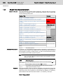


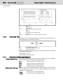
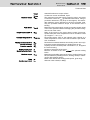
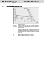

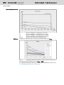
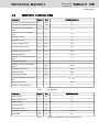
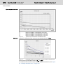


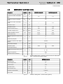
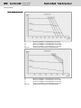

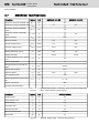


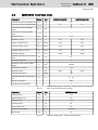
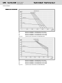
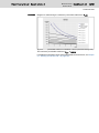

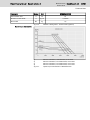
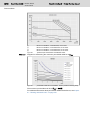
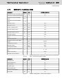

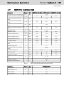

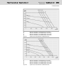

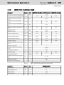


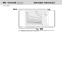


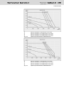


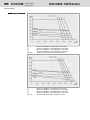


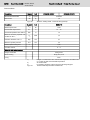
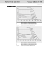


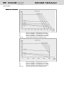

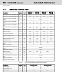


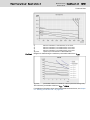

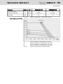

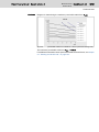
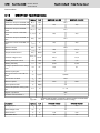
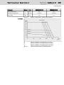


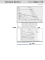
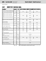

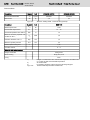
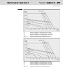
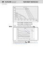

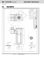

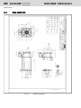

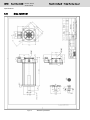

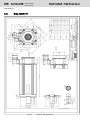
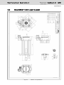


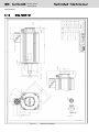


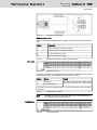


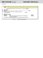


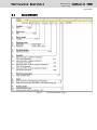


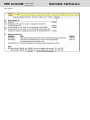
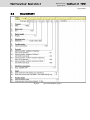


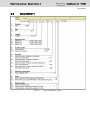


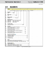
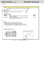

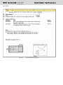

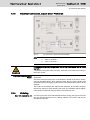
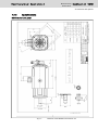
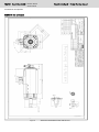


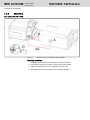

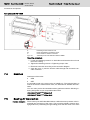
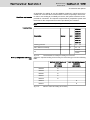


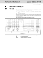


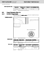
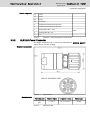


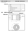


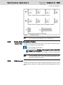


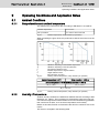

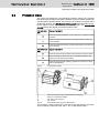
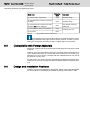

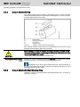
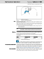
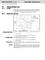


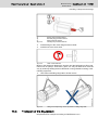


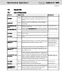
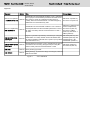


![[Download] azionamenti-hcs01](http://vs1.manualzilla.com/store/data/006141009_1-1242967de3765f3b826dc0b688197751-150x150.png)