1
Electric Drives and Controls Hydraulics Linear Motion and Assembly Technologies Pneumatics Service Rexroth IndraControl VCP 20 Rexroth IndraDyn H Frameless Synchronous Spindle Motors Project Planning Manual R911297895 Edition 02 About this Documentation Title Rexroth IndraDyn H Rexroth IndraDyn H Frameless Synchronous Spindle Motors Type of Documentation Document Typecode Internal File Refernece Purpose of Documentation Project Planning Manual DOK-MOTOR*-MBS-H******-PR02-EN-P • 29789502_book.doc • Document Number 120-1500-B327-02/EN This documentation .... • explains product features and applications, technical data as well as conditions and limits for operation. • provides guidelines for product selection, application, handling and operation. Record of Revisions Copyright Description Release date Notes DOK-MOTOR*-MBS-H******-PR01-EN-P Sept04 1st edition DOK-MOTOR*-MBS-H******-PR02-EN-P May05 1st reprint Bosch Rexroth AG, 2005 Copying this document, giving it to others and the use or communication of the contents thereof without express authority, are forbidden. Offenders are liable for the payment of damages. All rights are reserved in the event of the grant of a patent or the registration of a utility model or design (DIN34-1). Validity Published by The specified data is for product description purposes only and may not be deemed to be guaranteed unless expressly confirmed in the contract. All rights are reserved with respect to the content of this documentation and the availability of the product. Bosch Rexroth AG Bgm.-Dr.-Nebel-Str. 2 • D-97816 Lohr a. Main Telefon +49 (0)93 52 / 40-0 • Tx 68 94 21 • Fax +49 (0)93 52 / 40-48 85 http://www.boschrexroth.com/ Abt. BRC/EDM1 (FS) Note This document has been printed on chlorine-free bleached paper. DOK-MOTOR*-MBS-H******-PR02-EN-P Rexroth IndraDyn H Table of Contents I Table of Contents 1 Introduction to the Product 1-1 About this Documentation ..................................................................................................................1-2 Additional Components........................................................................................................1-3 Feedback ............................................................................................................................1-3 Standards............................................................................................................................1-4 2 Safety Instructions for Electric Drives and Controls 2-1 2.1 Introduction ..............................................................................................................................2-1 2.2 Explanations ............................................................................................................................2-1 2.3 Hazards by Improper Use.........................................................................................................2-2 2.4 General Information..................................................................................................................2-3 2.5 Protection Against Contact with Electrical Parts ........................................................................2-5 2.6 Protection Against Electric Shock by Protective Low Voltage (PELV) ........................................2-6 2.7 Protection Against Dangerous Movements ...............................................................................2-7 2.8 Protection Against Magnetic and Electromagnetic Fields During Operation and Mounting ..................................................................................................................................2-9 2.9 Protection Against Contact with Hot Parts...............................................................................2-10 2.10 Protection During Handling and Mounting...............................................................................2-10 2.11 Battery Safety.........................................................................................................................2-10 2.12 Protection Against Pressurized Systems.................................................................................2-11 3 Important directions for use 3.1 3-1 Appropriate use........................................................................................................................3-1 Introduction .........................................................................................................................3-1 Areas of use and application................................................................................................3-2 3.2 4 Inappropriate use .....................................................................................................................3-2 Technical Data 4.1 4-1 Definitions ................................................................................................................................4-1 Operating Modes.................................................................................................................4-1 ON Time..............................................................................................................................4-1 Parameters .........................................................................................................................4-2 Operating characteristic.......................................................................................................4-3 4.2 Data Sheet Size 102 (preliminary) ............................................................................................4-4 4.3 Data Sheet Size 142 (preliminary) ............................................................................................4-5 4.4 Data Sheet Size 162 ................................................................................................................4-6 4.5 Data Sheet Size 182 ................................................................................................................4-7 4.6 Data Sheet Size 202 ................................................................................................................4-8 4.7 Data Sheet Size 242 ................................................................................................................4-9 DOK-MOTOR*-MBS-H******-PR02-EN-P II Table of Contents Rexroth IndraDyn H 4.8 Data Sheet Size 272 ..............................................................................................................4-10 4.9 Data Sheet Size 312 ..............................................................................................................4-11 4.10 Preliminary Data Sheet Size 382 ............................................................................................4-12 5 Dimensional Sheet IndraDyn H 5.1 5-1 Size 162...................................................................................................................................5-2 MBS162 with Axial Cooling Connection and Rotor Design “1N” ...........................................5-2 MBS162 with Axial Cooling Connection and Rotor Design “2N” ...........................................5-3 MSS162, axial cooling connection .......................................................................................5-4 MRS162 with 1N Design (Smooth Hole) ..............................................................................5-5 MRS162 with 2N Design (Step Interference Fit)...................................................................5-6 5.2 Size 182...................................................................................................................................5-7 MBS182 with Axial Cooling Connection and Rotor Design “1N” ...........................................5-7 MBS182 with Axial Cooling Connection and Rotor Design “2N” ...........................................5-8 MBS182A with Radial Cooling Connection and Rotor Design “1N”.......................................5-9 MSS182, axial cooling connection .....................................................................................5-10 MSS182, radial cooling connection ....................................................................................5-11 MRS182 with 1N Design (Smooth Hole) ............................................................................5-12 MRS182 with 2N Design (Step Interference Fit).................................................................5-13 5.3 Size 202.................................................................................................................................5-14 MBS202 with Axial Cooling Connection and Rotor Design “1N” .........................................5-14 MBS202 with Axial Cooling Connection and Rotor Design “2N” .........................................5-15 MSS202, axial cooling connection .....................................................................................5-16 MRS202 with 1N Design (Smooth Hole) ............................................................................5-17 MRS202 with 2N Design (Step Interference Fit).................................................................5-18 5.4 Size 242.................................................................................................................................5-19 MBS242 with Axial Cooling Connection and Rotor Design “1N” .........................................5-19 MBS242 with Axial Cooling Connection and Rotor Design “2N” .........................................5-20 MSS242, axial cooling connection .....................................................................................5-21 MRS242 in design 1N........................................................................................................5-22 MRS242 in design 2N........................................................................................................5-23 5.5 Size 272.................................................................................................................................5-24 MBS272 with Axial Cooling Connection and Rotor Design “1N” .........................................5-24 MBS272 with Axial Cooling Connection and Rotor Design “2N” .........................................5-25 MSS272, axial cooling connection .....................................................................................5-26 MRS272 in design 1N........................................................................................................5-27 MRS272 in design 2N........................................................................................................5-28 5.6 Dimension Sheet Size 312 .....................................................................................................5-29 MBS312 with Axial Cooling Connection and Rotor Design “1N” .........................................5-29 MBS312 with Axial Cooling Connection and Rotor Design “2N” .........................................5-30 MBS312 with Radial Cooling Connection and Rotor Design “1N” .......................................5-31 MBS312 with Radial Cooling Connection and Rotor Design “2N” .......................................5-32 MSS312, axial cooling connection .....................................................................................5-33 MRS312 in design 1N........................................................................................................5-34 MRS312 in design 2N........................................................................................................5-35 5.7 Size 382.................................................................................................................................5-36 DOK-MOTOR*-MBS-H******-PR02-EN-P Rexroth IndraDyn H Table of Contents III MBS382 with Axial Cooling Connection and Rotor Design “1N” .........................................5-36 MBS382 with Axial Cooling Connection and Rotor Design “2N” .........................................5-37 MSS382, axial cooling connection .....................................................................................5-38 MRS382 in design 1N........................................................................................................5-39 MRS382 in design 2N........................................................................................................5-40 6 Type Codes of IndraDyn H Motors 6.1 6-1 Introduction ..............................................................................................................................6-1 Type Code for Rotor “MRS” .................................................................................................6-3 Type Code for Stator “MSS” ................................................................................................6-4 6.2 Type Code MRS102.................................................................................................................6-6 6.3 Type Code MSS102 .................................................................................................................6-6 6.4 Type Code MRS142.................................................................................................................6-7 6.5 Type Code MSS142 .................................................................................................................6-7 6.6 Type Code MRS162.................................................................................................................6-8 6.7 Type Code MSS162 .................................................................................................................6-8 6.8 Type Code MRS182.................................................................................................................6-9 6.9 Type Code MSS182 .................................................................................................................6-9 6.10 Type Code MRS202...............................................................................................................6-10 6.11 Type Code MSS202 ...............................................................................................................6-10 6.12 Type Code MRS242...............................................................................................................6-11 6.13 Type Code MSS242 ...............................................................................................................6-11 6.14 Type Code MRS272...............................................................................................................6-12 6.15 Type Code MSS272 ...............................................................................................................6-12 6.16 Type Code MRS312...............................................................................................................6-13 6.17 Type Code MSS312 ...............................................................................................................6-13 6.18 Type Code MRS382...............................................................................................................6-14 6.19 Type Code MSS382 ...............................................................................................................6-14 7 Accessories 7.1 8 7-1 O-Rings for the Rotors..............................................................................................................7-1 Connection Techniques 8-1 8.1 Notes .......................................................................................................................................8-1 8.2 Power connector ......................................................................................................................8-2 Ground Connection .............................................................................................................8-4 Connection with Terminal Box .............................................................................................8-5 Connection with Coupling ....................................................................................................8-7 8.3 Connection Designations on the Drive Device ..........................................................................8-8 8.4 Temperature Sensors...............................................................................................................8-8 8.5 Motor Cooling...........................................................................................................................8-9 Operating Pressure ...........................................................................................................8-11 8.6 9 Motor Encoder........................................................................................................................8-11 Notes Regarding Application 9.1 9-1 Setup Elevation and Ambient Temperature...............................................................................9-1 DOK-MOTOR*-MBS-H******-PR02-EN-P IV Table of Contents Rexroth IndraDyn H 9.2 Humidity...................................................................................................................................9-2 9.3 Vibration and Shock .................................................................................................................9-2 Vibration..............................................................................................................................9-2 Shock..................................................................................................................................9-2 9.4 Protection Class .......................................................................................................................9-3 9.5 Compatibility ............................................................................................................................9-4 9.6 Motor Cooling...........................................................................................................................9-4 Coolants..............................................................................................................................9-5 Coolant Inlet Temperature ...................................................................................................9-6 Thermal Behavior ................................................................................................................9-7 Sizing the Cooling Circuit.....................................................................................................9-8 Liquid Cooling System.......................................................................................................9-11 9.7 Motor Temperature Monitor ....................................................................................................9-15 9.8 Motor Direction of Rotation .....................................................................................................9-18 9.9 Design of Rotor and Assembly Principle of Rotor/Spindle Shaft ..............................................9-18 Rotor with Smooth Bore.....................................................................................................9-18 Rotor with Step Interference Fit .........................................................................................9-20 9.10 Stator Installation Principles....................................................................................................9-21 9.11 Regenerative Power Uptake...................................................................................................9-22 9.12 External Components .............................................................................................................9-23 Motor Encoders .................................................................................................................9-23 Bearings............................................................................................................................9-25 10 Handling, Transport and Storage 10-1 10.1 General ..................................................................................................................................10-1 10.2 Delivery Status .......................................................................................................................10-1 Factory Test ......................................................................................................................10-2 Test on the Customer Side ................................................................................................10-2 Scope of Delivery ..............................................................................................................10-2 10.3 Identification...........................................................................................................................10-3 10.4 Transport and Storage............................................................................................................10-5 Transport...........................................................................................................................10-6 Storage .............................................................................................................................10-8 11 Assembly Instructions 11-1 11.1 General Notes Regarding Safety ............................................................................................11-3 11.2 Aids for Assembly and Disassembly .......................................................................................11-4 11.3 Securing Screws with LOCTITE 1)...........................................................................................11-6 11.4 Assembling a Rotor with a Smooth Shaft on the Spindle.........................................................11-7 Parts / Scope of Delivery of the Rotor with a Smooth Shaft ................................................11-7 Before Assembly ...............................................................................................................11-7 Shrink-fitting the Rotor onto the Spindle .............................................................................11-8 11.5 Assembling a Rotor with a Step interference fit on the Spindle..............................................11-10 Parts / Scope of Delivery of the Rotor with a Step interference fit .....................................11-10 Before Assembly .............................................................................................................11-10 Shrink-fitting the Rotor onto the Spindle ...........................................................................11-11 DOK-MOTOR*-MBS-H******-PR02-EN-P Rexroth IndraDyn H Table of Contents V 11.6 Measures to be Taken in the Case of Faulty Assembly .........................................................11-13 11.7 Balancing the Rotor..............................................................................................................11-15 11.8 Removing the Rotor with a Step interference fit from the Spindle ..........................................11-16 11.9 Installing the Stator in the Spindle Housing...........................................................................11-18 Stator Parts / Scope of Delivery .......................................................................................11-18 Before Assembly .............................................................................................................11-18 Installation Procedure......................................................................................................11-19 Connecting the Stator......................................................................................................11-20 11.10 Removing the Stator from the Spindle Housing.....................................................................11-20 11.11 Mounting the Motor Spindle ..................................................................................................11-21 11.12 Dismantling the Motor Spindle ..............................................................................................11-24 12 Startup, Operation and Maintenance 12-1 12.1 General Information on Startup IndraDyn H Motors.................................................................12-1 12.2 Basic Requirements ...............................................................................................................12-2 Check of all Electrical and Mechanical Components ..........................................................12-2 Materials ...........................................................................................................................12-3 12.3 General Startup Procedure.....................................................................................................12-4 12.4 Parametrization ......................................................................................................................12-5 Entering Motor Parameters................................................................................................12-5 Entering Encoder System Parameters ...............................................................................12-7 Entering Drive Limitations and Application-Dependent Parameters ....................................12-7 12.5 Determining the Polarity of the Encoder System .....................................................................12-8 12.6 Commutation Adjustment .......................................................................................................12-9 12.7 Setting and Optimizing the Control Circuit.............................................................................12-11 General Procedure ..........................................................................................................12-11 12.8 Maintenance and Inspection of Motor components ...............................................................12-13 Check of Motor and Auxiliary Components ......................................................................12-13 Electrical Check of Motor Components ............................................................................12-13 12.9 Startup .................................................................................................................................12-14 Preparation .....................................................................................................................12-14 Execution ........................................................................................................................12-14 12.10 Deactivation .........................................................................................................................12-15 12.11 Dismantling ..........................................................................................................................12-15 12.12 Maintenance ........................................................................................................................12-16 Measures ........................................................................................................................12-16 Coolant Supply ................................................................................................................12-16 12.13 Troubleshooting ...................................................................................................................12-17 Excess temperature of motor housing..............................................................................12-18 High motor temperature values, but housing temperature is normal .................................12-18 Motor or machine generates vibrations ............................................................................12-19 Specified position is not attained......................................................................................12-19 13 Service & Support 13-1 13.1 Helpdesk ................................................................................................................................13-1 13.2 Service-Hotline.......................................................................................................................13-1 DOK-MOTOR*-MBS-H******-PR02-EN-P VI Table of Contents Rexroth IndraDyn H 13.3 Internet...................................................................................................................................13-1 13.4 Vor der Kontaktaufnahme... - Before contacting us... ..............................................................13-1 13.5 Kundenbetreuungsstellen - Sales & Service Facilities.............................................................13-2 14 Index 14-1 DOK-MOTOR*-MBS-H******-PR02-EN-P Introduction to the Product 1-1 Rexroth IndraDyn H 1 Introduction to the Product New technologies with high economic benefits are posing increasingly extreme demands on the acceleration, velocity and precision of motors. Rexroth IndraDyn H motors are state-of-the-art, high-speed synchronous frameless motors, optimized for high torques at high speeds. They consist of a stator with a three-phase winding and a rotor with permanent magnets. Due to a wide constant-power range, the brief startup times and the low rotor temperature, these motors are especially suitable for use in motor spindles. The novel cooling system, which is self-contained in the motor, reduces expenses for the machine manufacturer and increases the cooling efficiency and capacity. IndradynH-Stat_Rot.tif Fig. 1-1: Examples of IndraDyn H stator and rotor Rexroth IndraDyn H motors are used mainly as direct drives in motor spindles. The position of the motor between the main spindle bearings gives the motor spindle a high rigidity. As a result, the main spindle and the C axis can be operated with only one drive in grinding machines, for example. Motor spindles are used for turning, milling and grinding in machine tools, transfer lines, processing centers and special-purpose machines. DOK-MOTOR*-MBS-H******-PR02-EN-P 1-2 Introduction to the Product Rexroth IndraDyn H Performance list The following diagram gives an overview of the performance range of the IndraDyn H motors. 7000 Maximaldrehmoment M max Maximum Torque Mmax Drehmoment in Nm Torque in Nm 6000 Bemessungsdrehmoment MN Rated Torque MN 5000 4000 3000 2000 1000 102 142 162 182 202 242 272 312 382 0 A B D F J Baugröße Size Fig. 1-2: IndraDyn H performance range About this Documentation Document structure This documentation includes safety instructions, technical data and operating instructions. The following setup provides an overview of the contents of this documentation. Chapter Title Content 1 Introduction Introduction to the product and notes 2 Important instructions on use 3 Safety 4 Technical data 5 Dimension sheets 6 Type code 7 Accessories 8 Connection techniques 9 Notes on application 10 Handling & transport 11 Installation 12 Operation 13 Service & support 14 Index Important safety instructions Product description Practice For planners and projectors For operating and maintenance personnel Additional information Fig. 1-3: Chapter structure DOK-MOTOR*-MBS-H******-PR02-EN-P Introduction to the Product 1-3 Rexroth IndraDyn H Supplementary Documentation To design the IndraDyn H motor type drive systems, you may need additional documentation depending on the devices used. Rexroth provides all product documentation on CD in PDF format. To design a system, you will not need all the documentation included on the CD. Note: All documentation on the CD is also available in a printed version. You can order the required product documentation from your Rexroth sales office. Material No. Title / description R911281882 -Product documentation Electric Drives and Controls Version xx 1) DOK-GENRL-CONTR*DRIVE-GNxx-DE-D650 R911281883 -Product documentation Electric Drives and Controls Version xx 1) DOK-GENRL-CONTR*DRIVE-GNxx-EN-D650 1) The index (e.g. ..02-...) identifies the version of the CD. Fig. 1-4: Supplementary documentation Additional Components Documentation for external systems which are connected to BOSCH REXROTH components are not included in the scope of delivery and must be ordered directly from the corresponding manufacturers. For information on the manufacturers, see chapter 9 "Notes on Application". Feedback Your experiences are an essential part of the process of improving both the product and the documentation. Please do not hesitate to inform us of any mistakes you detect in this documentation or of any modifications you might desire. We would appreciate your feedback. Please send your remarks to: REXROTH INDRAMAT GmbH Dep. BRC/EDM1 Bürgermeister-Dr.-Nebel-Strasse 2 D-97816 Lohr, Germany Fax +49 (0) 93 52 / 40-43 80 DOK-MOTOR*-MBS-H******-PR02-EN-P 1-4 Introduction to the Product Rexroth IndraDyn H Standards This documentation refers to German, European and international technical standards. Documents and sheets on standards are subject to copyright protection and may not be passed on to third parties by REXROTH INDRAMAT. If necessary, please address the authorized sales offices or, in Germany, directly to: BEUTH Verlag GmbH Burggrafenstrasse 6 10787 Berlin Phone +49-(0)30-26 01-22 60, Fax +49-(0)30-26 01-12 60 Internet: http://www.din.de/beuthEmail: [email protected] DOK-MOTOR*-MBS-H******-PR02-EN-P Safety Instructions for Electric Drives and Controls 2-1 Rexroth IndraDyn H 2 Safety Instructions for Electric Drives and Controls 2.1 Introduction Read these instructions before the initial startup of the equipment in order to eliminate the risk of bodily harm or material damage. Follow these safety instructions at all times. Do not attempt to install or start up this equipment without first reading all documentation provided with the product. Read and understand these safety instructions and all user documentation of the equipment prior to working with the equipment at any time. If you do not have the user documentation for your equipment, contact your local Bosch Rexroth representative to send this documentation immediately to the person or persons responsible for the safe operation of this equipment. If the equipment is resold, rented or transferred or passed on to others, then these safety instructions must be delivered with the equipment. WARNING 2.2 Improper use of this equipment, failure to follow the safety instructions in this document or tampering with the product, including disabling of safety devices, may result in material damage, bodily harm, electric shock or even death! Explanations The safety instructions describe the following degrees of hazard seriousness in compliance with ANSI Z535. The degree of hazard seriousness informs about the consequences resulting from noncompliance with the safety instructions. Warning symbol with signal word Degree of hazard seriousness according to ANSI Death or severe bodily harm will occur. DANGER Death or severe bodily harm may occur. WARNING Bodily harm or material damage may occur. CAUTION Fig. 2-1: DOK-MOTOR*-MBS-H******-PR02-EN-P Hazard classification (according to ANSI Z535) 2-2 Safety Instructions for Electric Drives and Controls 2.3 Rexroth IndraDyn H Hazards by Improper Use High voltage and high discharge current! Danger to life or severe bodily harm by electric shock! DANGER Dangerous movements! Danger to life, severe bodily harm or material damage by unintentional motor movements! DANGER High electrical voltage due to wrong connections! Danger to life or bodily harm by electric shock! WARNING Health hazard for persons with heart pacemakers, metal implants and hearing aids in proximity to electrical equipment! WARNING Surface of machine housing could be extremely hot! Danger of injury! Danger of burns! CAUTION CAUTION Risk of injury due to improper handling! Bodily harm caused by crushing, shearing, cutting and mechanical shock or incorrect handling of pressurized systems! Risk of injury due to incorrect handling of batteries! CAUTION DOK-MOTOR*-MBS-H******-PR02-EN-P Safety Instructions for Electric Drives and Controls 2-3 Rexroth IndraDyn H 2.4 General Information • Bosch Rexroth AG is not liable for damages resulting from failure to observe the warnings provided in this documentation. • Read the operating, maintenance and safety instructions in your language before starting up the machine. If you find that you cannot completely understand the documentation for your product, please ask your supplier to clarify. • Proper and correct transport, storage, assembly and installation as well as care in operation and maintenance are prerequisites for optimal and safe operation of this equipment. • Only persons who are trained and qualified for the use and operation of the equipment may work on this equipment or within its proximity. • The persons are qualified if they have sufficient knowledge of the assembly, installation and operation of the equipment as well as an understanding of all warnings and precautionary measures noted in these instructions. • Furthermore, they must be trained, instructed and qualified to switch electrical circuits and equipment on and off in accordance with technical safety regulations, to ground them and to mark them according to the requirements of safe work practices. They must have adequate safety equipment and be trained in first aid. • Only use spare parts and accessories approved by the manufacturer. • Follow all safety regulations and requirements for the specific application as practiced in the country of use. • The equipment is designed for installation in industrial machinery. • The ambient conditions given in the product documentation must be observed. • Use only safety features and applications that are clearly and explicitly approved in the Project Planning Manual. If this is not the case, they are excluded. The following areas of use and application, for example, include safety features and applications: construction cranes, elevators used for people or freight, devices and vehicles to transport people, medical applications, refinery plants, transport of hazardous goods, nuclear applications, applications in which electrical devices with vital functions can be electromagnetically disturbed, mining, food processing, control of protection equipment (also in a machine). • The information given in the documentation of the product with regard to the use of the delivered components contains only examples of applications and suggestions. The machine and installation manufacturer must • make sure that the delivered components are suited for his individual application and check the information given in this documentation with regard to the use of the components, • make sure that his application complies with the applicable safety regulations and standards and carry out the required measures, modifications and complements. • Startup of the delivered components is only permitted once it is sure that the machine or installation in which they are installed complies with the national regulations, safety specifications and standards of the application. DOK-MOTOR*-MBS-H******-PR02-EN-P 2-4 Safety Instructions for Electric Drives and Controls Rexroth IndraDyn H • Operation is only permitted if the national EMC regulations for the application are met. The instructions for installation in accordance with EMC requirements can be found in the documentation "EMC in Drive and Control Systems". The machine or installation manufacturer is responsible for compliance with the limiting values as prescribed in the national regulations. • Technical data, connections and operational conditions are specified in the product documentation and must be followed at all times. DOK-MOTOR*-MBS-H******-PR02-EN-P Safety Instructions for Electric Drives and Controls 2-5 Rexroth IndraDyn H 2.5 Protection Against Contact with Electrical Parts Note: This section refers to equipment and drive components with voltages above 50 Volts. Touching live parts with voltages of 50 Volts and more with bare hands or conductive tools or touching ungrounded housings can be dangerous and cause electric shock. In order to operate electrical equipment, certain parts must unavoidably have dangerous voltages applied to them. High electrical voltage! Danger to life, severe bodily harm by electric shock! DANGER DOK-MOTOR*-MBS-H******-PR02-EN-P ⇒ Only those trained and qualified to work with or on electrical equipment are permitted to operate, maintain or repair this equipment. ⇒ Follow general construction and safety regulations when working on high voltage installations. ⇒ Before switching on power the ground wire must be permanently connected to all electrical units according to the connection diagram. ⇒ Do not operate electrical equipment at any time, even for brief measurements or tests, if the ground wire is not permanently connected to the points of the components provided for this purpose. ⇒ Before working with electrical parts with voltage higher than 50 V, the equipment must be disconnected from the mains voltage or power supply. Make sure the equipment cannot be switched on again unintended. ⇒ The following should be observed with electrical drive and filter components: ⇒ Wait thirty (30) minutes after switching off power to allow capacitors to discharge before beginning to work. Measure the voltage on the capacitors before beginning to work to make sure that the equipment is safe to touch. ⇒ Never touch the electrical connection points of a component while power is turned on. ⇒ Install the covers and guards provided with the equipment properly before switching the equipment on. Prevent contact with live parts at any time. ⇒ A residual-current-operated protective device (RCD) must not be used on electric drives! Indirect contact must be prevented by other means, for example, by an overcurrent protective device. ⇒ Electrical components with exposed live parts and uncovered high voltage terminals must be installed in a protective housing, for example, in a control cabinet. 2-6 Safety Instructions for Electric Drives and Controls Rexroth IndraDyn H To be observed with electrical drive and filter components: High electrical voltage on the housing! High leakage current! Danger to life, danger of injury by electric shock! DANGER 2.6 ⇒ Connect the electrical equipment, the housings of all electrical units and motors permanently with the safety conductor at the ground points before power is switched on. Look at the connection diagram. This is even necessary for brief tests. ⇒ Connect the safety conductor of the electrical equipment always permanently and firmly to the supply mains. Leakage current exceeds 3.5 mA in normal operation. ⇒ Use a copper conductor with at least 10 mm² cross section over its entire course for this safety conductor connection! ⇒ Prior to startups, even for brief tests, always connect the protective conductor or connect with ground wire. Otherwise, high voltages can occur on the housing that lead to electric shock. Protection Against Electric Shock by Protective Low Voltage (PELV) All connections and terminals with voltages between 0 and 50 Volts on Rexroth products are protective low voltages designed in accordance with international standards on electrical safety. High electrical voltage due to wrong connections! Danger to life, bodily harm by electric shock! WARNING ⇒ Only connect equipment, electrical components and cables of the protective low voltage type (PELV = Protective Extra Low Voltage) to all terminals and clamps with voltages of 0 to 50 Volts. ⇒ Only electrical circuits may be connected which are safely isolated against high voltage circuits. Safe isolation is achieved, for example, with an isolating transformer, an opto-electronic coupler or when battery-operated. DOK-MOTOR*-MBS-H******-PR02-EN-P Rexroth IndraDyn H 2.7 Safety Instructions for Electric Drives and Controls 2-7 Protection Against Dangerous Movements Dangerous movements can be caused by faulty control of the connected motors. Some common examples are: • improper or wrong wiring of cable connections • incorrect operation of the equipment components • wrong input of parameters before operation • malfunction of sensors, encoders and monitoring devices • defective components • software or firmware errors Dangerous movements can occur immediately after equipment is switched on or even after an unspecified time of trouble-free operation. The monitoring in the drive components will normally be sufficient to avoid faulty operation in the connected drives. Regarding personal safety, especially the danger of bodily injury and material damage, this alone cannot be relied upon to ensure complete safety. Until the integrated monitoring functions become effective, it must be assumed in any case that faulty drive movements will occur. The extent of faulty drive movements depends upon the type of control and the state of operation. DOK-MOTOR*-MBS-H******-PR02-EN-P 2-8 Safety Instructions for Electric Drives and Controls Rexroth IndraDyn H Dangerous movements! Danger to life, risk of injury, severe bodily harm or material damage! DANGER ⇒ Ensure personal safety by means of qualified and tested higher-level monitoring devices or measures integrated in the installation. Unintended machine motion is possible if monitoring devices are disabled, bypassed or not activated. ⇒ Pay attention to unintended machine motion or other malfunction in any mode of operation. ⇒ Keep free and clear of the machine’s range of motion and moving parts. Possible measures to prevent people from accidentally entering the machine’s range of motion: - use safety fences - use safety guards - use protective coverings - install light curtains or light barriers ⇒ Fences and coverings must be strong enough to resist maximum possible momentum, especially if there is a possibility of loose parts flying off. ⇒ Mount the emergency stop switch in the immediate reach of the operator. Verify that the emergency stop works before startup. Don’t operate the machine if the emergency stop is not working. ⇒ Isolate the drive power connection by means of an emergency stop circuit or use a starting lockout to prevent unintentional start. ⇒ Make sure that the drives are brought to a safe standstill before accessing or entering the danger zone. Safe standstill can be achieved by switching off the power supply contactor or by safe mechanical locking of moving parts. ⇒ Secure vertical axes against falling or dropping after switching off the motor power by, for example: - mechanically securing the vertical axes - adding an external braking/ arrester/ clamping mechanism - ensuring sufficient equilibration of the vertical axes The standard equipment motor brake or an external brake controlled directly by the drive controller are not sufficient to guarantee personal safety! DOK-MOTOR*-MBS-H******-PR02-EN-P Safety Instructions for Electric Drives and Controls 2-9 Rexroth IndraDyn H ⇒ Disconnect electrical power to the equipment using a master switch and secure the switch against reconnection for: - maintenance and repair work - cleaning of equipment - long periods of discontinued equipment use ⇒ Prevent the operation of high-frequency, remote control and radio equipment near electronics circuits and supply leads. If the use of such equipment cannot be avoided, verify the system and the installation for possible malfunctions in all possible positions of normal use before initial startup. If necessary, perform a special electromagnetic compatibility (EMC) test on the installation. 2.8 Protection Against Magnetic and Electromagnetic Fields During Operation and Mounting Magnetic and electromagnetic fields generated near current-carrying conductors and permanent magnets in motors represent a serious health hazard to persons with heart pacemakers, metal implants and hearing aids. Health hazard for persons with heart pacemakers, metal implants and hearing aids in proximity to electrical equipment! WARNING ⇒ Persons with heart pacemakers, hearing aids and metal implants are not permitted to enter the following areas: - Areas in which electrical equipment and parts are mounted, being operated or started up. - Areas in which parts of motors with permanent magnets are being stored, operated, repaired or mounted. ⇒ If it is necessary for a person with a heart pacemaker to enter such an area, then a doctor must be consulted prior to doing so. Heart pacemakers that are already implanted or will be implanted in the future, have a considerable variation in their electrical noise immunity. Therefore there are no rules with general validity. ⇒ Persons with hearing aids, metal implants or metal pieces must consult a doctor before they enter the areas described above. Otherwise, health hazards will occur. DOK-MOTOR*-MBS-H******-PR02-EN-P 2-10 Safety Instructions for Electric Drives and Controls 2.9 Rexroth IndraDyn H Protection Against Contact with Hot Parts Housing surfaces could be extremely hot! Danger of injury! Danger of burns! CAUTION ⇒ Do not touch housing surfaces near sources of heat! Danger of burns! ⇒ After switching the equipment off, wait at least ten (10) minutes to allow it to cool down before touching it. ⇒ Do not touch hot parts of the equipment, such as housings with integrated heat sinks and resistors. Danger of burns! 2.10 Protection During Handling and Mounting Under certain conditions, incorrect handling and mounting of parts and components may cause injuries. Risk of injury by incorrect handling! Bodily harm caused by crushing, shearing, cutting and mechanical shock! CAUTION ⇒ Observe general installation and safety instructions with regard to handling and mounting. ⇒ Use appropriate mounting and transport equipment. ⇒ Take precautions to avoid pinching and crushing. ⇒ Use only appropriate tools. If specified by the product documentation, special tools must be used. ⇒ Use lifting devices and tools correctly and safely. ⇒ For safe protection wear appropriate protective clothing, e.g. safety glasses, safety shoes and safety gloves. ⇒ Never stand under suspended loads. ⇒ Clean up liquids from the floor immediately to prevent slipping. 2.11 Battery Safety Batteries contain reactive chemicals in a solid housing. Inappropriate handling may result in injuries or material damage. DOK-MOTOR*-MBS-H******-PR02-EN-P Safety Instructions for Electric Drives and Controls 2-11 Rexroth IndraDyn H Risk of injury by incorrect handling! CAUTION Note: ⇒ Do not attempt to reactivate discharged batteries by heating or other methods (danger of explosion and cauterization). ⇒ Never charge non-chargeable batteries (danger of leakage and explosion). ⇒ Never throw batteries into a fire. ⇒ Do not dismantle batteries. ⇒ Do not damage electrical components installed in the equipment. Be aware of environmental protection and disposal! The batteries contained in the product should be considered as hazardous material for land, air and sea transport in the sense of the legal requirements (danger of explosion). Dispose batteries separately from other waste. Observe the legal requirements in the country of installation. 2.12 Protection Against Pressurized Systems Certain motors and drive controllers, corresponding to the information in the respective Project Planning Manual, must be provided with pressurized media, such as compressed air, hydraulic oil, cooling fluid and cooling lubricant supplied by external systems. Incorrect handling of the supply and connections of pressurized systems can lead to injuries or accidents. In these cases, improper handling of external supply systems, supply lines or connections can cause injuries or material damage. Danger of injury by incorrect handling of pressurized systems ! CAUTION Note: DOK-MOTOR*-MBS-H******-PR02-EN-P ⇒ Do not attempt to disassemble, to open or to cut a pressurized system (danger of explosion). ⇒ Observe the operation instructions of the respective manufacturer. ⇒ Before disassembling pressurized systems, release pressure and drain off the fluid or gas. ⇒ Use suitable protective clothing (for example safety glasses, safety shoes and safety gloves) ⇒ Remove any fluid that has leaked out onto the floor immediately. Environmental protection and disposal! The media used in the operation of the pressurized system equipment may not be environmentally compatible. Media that are damaging the environment must be disposed separately from normal waste. Observe the legal requirements in the country of installation. 2-12 Safety Instructions for Electric Drives and Controls Rexroth IndraDyn H Notes DOK-MOTOR*-MBS-H******-PR02-EN-P Important directions for use 3-1 Rexroth IndraDyn H 3 Important directions for use 3.1 Appropriate use Introduction Bosch Rexroth products represent state-of-the-art developments and manufacturing. They are tested prior to delivery to ensure operating safety and reliability. The products may only be used in the manner that is defined as appropriate. If they are used in an inappropriate manner, then situations can develop that may lead to property damage or injury to personnel. Note: Bosch Rexroth, as manufacturer, is not liable for any damages resulting from inappropriate use. In such cases, the guarantee and the right to payment of damages resulting from inappropriate use are forfeited. The user alone carries all responsibility of the risks. Before using Bosch Rexroth products, make sure that all the prerequisites for appropriate use of the products are satisfied: • Personnel that in any way, shape or form uses our products must first read and understand the relevant safety instructions and be familiar with appropriate use. • If the product takes the form of hardware, then they must remain in their original state, in other words, no structural changes are permitted. It is not permitted to decompile software products or alter source codes. • Do not mount damaged or faulty products or use them in operation. • Make sure that the products have been installed in the manner described in the relevant documentation. DOK-MOTOR*-MBS-H******-PR02-EN-P 3-2 Important directions for use Rexroth IndraDyn H Areas of use and application High-speed synchronous frameless motors of the IndraDyn H line made by Bosch Rexroth are designed to be used as rotary main motors. Typical applications are in: • machine tools Several types of motors with differing drive power and different interfaces are available for application-specific uses. Control and monitoring of the motors may require additional sensors and actors. Note: The motors may only be used with the accessories and parts specified in this document. If a component has not been specifically named, then it may not be either mounted or connected. The same applies to cables and lines. Operation is only permitted in the specified configurations and combinations of components using the software and firmware as specified in the relevant function descriptions. Every drive controller has to be programmed before starting it up, making it possible for the motor to execute the specific functions of an application. The motors may only be operated under the assembly, installation and ambient conditions as described here (temperature, protection categories, humidity, EMC requirements, etc.) and in the position specified. 3.2 Inappropriate use Inappropriate use is defined as using the motors outside of the abovereferenced areas of application or under operating conditions other than described in the document and the technical data specified. IndraDyn H motors may not be used if • they are subject to operating conditions that do not meet the above specified ambient conditions. This includes, for example, operation under water, in the case of extreme temperature fluctuations or extremely high maximum temperatures or if • Bosch Rexroth has not specifically released them for that intended purpose. Please note the specifications outlined in the general Safety Instructions! DOK-MOTOR*-MBS-H******-PR02-EN-P Technical Data 4-1 Rexroth IndraDyn H 4 Technical Data 4.1 Definitions Operating Modes Bosch Rexroth motors are documented according to the test criteria and measuring methods of EN 60034-1. The stated technical data refer to the operating mode S1 (continuous operation) and S6 (periodic operation), each with liquid cooling with water as the cooling medium. P P PV PV Q Q Qmax Qmax DtP TC DtV t S1 S6 t MBS_Definitions1.EPS P: Capacity Electric losses PV: Θ: Temperature Θmax: Highest temperature (stator) t: Time T C: Cycle time Operating time with constant load ∆tP: ∆tV: Idle time Fig. 4-1: Operating modes according to EN 60034-1 :1998 ON Time The operating mode S6 is supplemented by specification of the duty cycle (ED) in %. The duty cycle is calculated as follows: ED = ED: Duty cycle in % T C: Cycle time ∆tP: On time Fig. 4-2: Duty cycle DOK-MOTOR*-MBS-H******-PR02-EN-P ∆t P ⋅100% TC 4-2 Technical Data Rexroth IndraDyn H Parameters Rated torque Available torque that can be output at the rated speed in operating mode S1 (continuous operation). Unit Newton meter (Nm). Rated speed Typical working speed as defined by the manufacturer. Depending on the particular application, other working speeds are possible (see speedtorque characteristic curve). Rated power Mechanical power output of the motor while running at rated speed and rated torque. The value is specified in kilowatts (kW). Rated current Phase current of the motor while running at rated speed and rated torque. The value is specified as root-mean-square value in amps (A). Maximum torque This is the maximum torque available using maximum current Imax .The achievable maximum torque depends on the drive controller used. Maximum current This is the maximum current (root-mean-square) of the motor at Mmax. The value is specified in amps (A). Rotor moment of inertia Jrot The moment of inertia of the rotor without bearings and encoder. Unit: kgm². Torque constant at 20 C KM_nenn This is the relation of torque increase to the motor phase-current (RMS). The value is specified in Nm/A. Valid up to the rated current Inenn. Voltage constant at 20°C KEMK_1000 Root-mean-square of the induced motor voltage with respect to the motor speed. The value is specified in V/1000 rpm. Winding resistance at 20°C R12 Winding resistance measured between two phases in ohms (Ω). Stator/Rotor mass mstat / mrot The mass of stator and rotor, without bearing and encoder, stated in kilogram (kg). Maximum speed nmax Maximum allowable speed of the motor in nmax. Value specified in RPM. Normally restricted by mechanical factors like centrifugal force or bearing stress. Number of pole pairs p Thermal time constant Tth Number of pole pairs of the motor. The time it takes for the motor temperature to rise to 63% of the final temperature with the stators loaded with rated torque in S1-operation and liquid cooling. Q 100% 63% ~ 5 x Tth Qmax Tth 1 0% t [min] MBS_Definitions2.EPS (1): Curve of the stator temperature over time Tth: Thermal time constant Fig. 4-3: Thermal time constant DOK-MOTOR*-MBS-H******-PR02-EN-P Technical Data 4-3 Rexroth IndraDyn H Operating characteristic The following sample characteristic curves explain the operating behavior of IndraDyn H motors, as does information found in the motor data sheet. M [Nm] Mmax MN Mnmax N nmax n [min-1] MBS_Definitions3.EPS [1]: [3]: [5]: Fig. 4-4: Rated torque Mnenn [2]: Rated speed nnenn Maximum torque Mmax [4]: Max. speed with max. torque nMmax Max. speed nmax Example motor characteristic curve Note: The attainable motor torque depends on the drive device used: it is available for IndraDyn H motors only if the drive controller is able to set the input control angle optimally. This is the case for all IndraDrive devices of Bosch Rexroth. If the drive controller is not able to do this, the reluctance torque cannot be used, and 10-15% less rated torque will be available. The maximum torque Mmax is available up to the speed nMmax. When the velocity rises, the available DC bus voltage is reduced by the velocitydependent back-EMF (electromotive force) of the motor. This leads to a reduction of the maximum torque with rising velocity. The specified characteristic curves can be linearly extrapolated to the existing voltages if the connection voltages or mains voltages are different. Example: n (UDC ,neu ) = Fig. 4-5: Conversion to DC bus voltage 750VDC n max 750 V = DOK-MOTOR*-MBS-H******-PR02-EN-P 540 V ⋅ n nenn Example for conversion Mmax 750 V = Mmax = cons tan t Fig. 4-6: UDC,neu 750 V ⋅ n max 540 V Mnenn 750 V = Mnenn = cons tan t n nenn 750 V = 750 V ⋅ n nenn 540 V Conversion-example to DC bus voltage 750VDC 4-4 Technical Data 4.2 Rexroth IndraDyn H Data Sheet Size 102 (preliminary) Description Symbol Unit Size 102 1 Motor data ) Frame length B D Winding code F 0800 Rated torque Mnenn Nm 12 20 33 Rated speed nnenn rpm Rated power Pnenn KW 10,1 16,8 27,6 8000 Rated current Inenn A 18 24 39 Maximum torque 2) Mmax Nm 30 45 75 Maximum current Imax A 48 69 100 nmax rpm A mm² Jrot kgm² KM_nenn Constant voltage at 20°C ) Winding resistance at 20°C Maximum speed 3 Minimum cross-section power cable ) 2,5 4 10 0,003 0,004 0,006 i.V. i.V. i.V. Nm/A i.p. i.p. i.p. KEMK_1000 V/ rpm i.p. i.p. i.p. R12 Ohm i.p. i.p. i.p. Ld mH i.p. i.p. i.p. 6 Moment of inertia for rotor type 1N ) Moment of inertia for rotor type 2N 7) Torque constant at 20°C 4 Winding inductivity longitudinal across 30000 Lq mH i.p. i.p. i.p. Tth min i.p. i.p. i.p. Rotor ) mrot kg 2,1 3,1 5,1 Stator mstat kg 7,7 10,1 14,9 Permissible ambient temperature Tum °C 0...+40 Permissible storage and transport temperature Tlager °C -20...+80 Thermal time constant 6 Mass Insulation class F International protection class acc. to IEC60050-411 Number of pole pairs IP00 p 3 Liquid Cooling Rated power loss PV_H2O kW Tein °C +10...+40 ∆Tdiff K 10 Qmin_H2O l/min i.p. i.p. i.p. ∆pdiff bar i.p. i.p. i.p. Permissible inlet pressure pmax bar Volume liquid cooling duct Vkuehl l 0,018 0,024 Coolant inlet temperature 5) 5 Coolant temperature rise at PV ) Necessary coolant flow for ∆Tdiff ) 5 Pressure drop at Qmin i.p. 1 ) 2 ) 3 ) 6 ) ) 7 i.p. i.p. i.p. 5 0,035 in preparation The determined values are root-mean-squares according to IEC 60034-1, if no others are given. Reference value 540 VDC The achievable maximum torque depends on the drive controller used. Rated according to EN60204-1 (1993), installation mode B2 and conversion factor for Bosch Rexroth cables at 40°C ambient temperature. When using other cables, larger cross sections may be necessary. For notes regarding connection cables on the motor see chapter 8.2 -1 EMV = electromagnetic force Root-mean-square applying to 1000 min . The data refer to operation with liquid cooling, cooling medium water. For additional notes for coolant inlet temperature see chapter 9.5 Values for rotor design “1N” with bigger available rotor internal diameter Values for rotor design “2N” with bigger available rotor internal diameter Fig. 4-7: Technical Data Size 102 (preliminary) DOK-MOTOR*-MBS-H******-PR02-EN-P Technical Data 4-5 Rexroth IndraDyn H 4.3 Data Sheet Size 142 (preliminary) Description Symbol Unit Size 142 1 Motor data ) Frame length B Winding code D F 0700 Rated torque Mnenn Nm 35 Rated speed nnenn rpm Rated power Pnenn KW 25,7 50 65 7000 36,7 47,6 Rated current Inenn A 38 55 68 Maximum torque 2) Mmax Nm 80 115 150 Maximum current Imax A 100 145 180 nmax rpm A mm² Jrot kgm² KM_nenn Constant voltage at 20°C ) Winding resistance at 20°C Maximum speed 3 Minimum cross-section power cable ) 10 16 16 0,011 0,014 0,017 i.V. i.V. i.V. Nm/A i.p. i.p. i.p. KEMK_1000 V/ rpm i.p. i.p. i.p. R12 Ohm i.p. i.p. i.p. Ld mH i.p. i.p. i.p. 6 Moment of inertia for rotor type 1N ) Moment of inertia for rotor type 2N 7) Torque constant at 20°C 4 Winding inductivity longitudinal across 28000 Lq mH i.p. i.p. i.p. Tth min i.p. i.p. i.p. Rotor ) mrot kg 4,6 6,5 8,3 Stator mstat kg 16,7 21,2 25,7 Permissible ambient temperature Tum °C 0...+40 Permissible storage and transport temperature Tlager °C -20...+80 Thermal time constant 6 Mass Insulation class F International protection class acc. to IEC60050-411 Number of pole pairs IP00 p 4 Liquid Cooling Rated power loss PV_H2O kW Tein °C +10...+40 ∆Tdiff K 10 Qmin_H2O l/min i.p. i.p. i.p. ∆pdiff bar i.p. i.p. i.p. Permissible inlet pressure pmax bar Volume liquid cooling duct Vkuehl l 0,028 0,036 Coolant inlet temperature 5) 5 Coolant temperature rise at PV ) Necessary coolant flow for ∆Tdiff ) 5 Pressure drop at Qmin 1 ) ) 3 ) 2 6 ) ) 7 i.p. i.p. i.p. 5 0,043 The determined values are root-mean-squares according to IEC 60034-1, if no others are given. Reference value 540 VDC The achievable maximum torque depends on the drive controller used. Rated according to EN60204-1 (1993), installation mode B2 and conversion factor for Bosch Rexroth cables at 40°C ambient temperature. When using other cables, larger cross sections may be necessary. For notes regarding connection cables on the motor see chapter 8.2 -1 EMV = electromagnetic force Root-mean-square applying to 1000 min . The data refer to operation with liquid cooling, cooling medium water. For additional notes for coolant inlet temperature see chapter 9.5 Values for rotor design “1N” with bigger available rotor internal diameter Values for rotor design “2N” with bigger available rotor internal diameter Fig. 4-8: Technical Data Size 142 (preliminary) DOK-MOTOR*-MBS-H******-PR02-EN-P 4-6 Technical Data 4.4 Rexroth IndraDyn H Data Sheet Size 162 Description Symbol Unit Size 162 1 Motor data ) Frame length B D F J Winding code 0400 0400 0310 0200 Rated torque Mnenn Nm 50 70 90 120 Rated speed nnenn rpm 4000 4000 3100 2000 Rated power Pnenn KW 20,9 29,3 29,2 25,1 Rated current Inenn A 42 64 64 64 Maximum torque 2) Mmax Nm 115 160 200 275 Maximum current Imax A 110 170 170 170 nmax rpm 16000 16000 12400 8000 A mm² 10 16 16 16 Jrot kgm² 0,014 0,018 0,022 0,028 0,016 0,02 0,024 0,03 KM_nenn Nm/A 1,24 1,09 1,406 1,875 Constant voltage at 20°C ) KEMK_1000 V/ rpm 90 90 110 160 Winding resistance at 20°C R12 Ohm 0,24 0,15 0,18 0,46 longitudinal Ld mH 1,04 1,04 1,1 2 across Lq mH 3,12 2,685 3,28 5,8 Tth min i.p. i.p. i.p. i.p. Rotor ) mrot kg 6,9 8,8 10,6 13,4 Stator mstat kg 22,0 28,1 34,1 46,1 Permissible ambient temperature Tum °C 0...+40 Permissible storage and transport temperature Tlager °C -20...+80 Maximum speed 3 Minimum cross-section power cable ) 6 Moment of inertia for rotor type 1N ) Moment of inertia for rotor type 2N 7) Torque constant at 20°C 4 Winding inductivity Thermal time constant 6 Mass Insulation class F International protection class acc. to IEC60050-411 Number of pole pairs IP00 p 4 Liquid Cooling Rated power loss PV_H2O kW Tein °C +10...+40 ∆Tdiff K 10 Qmin_H2O l/min ∆pdiff bar Permissible inlet pressure pmax bar Volume liquid cooling duct Vkuehl l Coolant inlet temperature 5) 5 Coolant temperature rise at PV ) Necessary coolant flow for ∆Tdiff ) 5 Pressure drop at Qmin i.p. 1 ) 2 ) 3 ) 6 ) ) 7 0,55 2 0,9 1,1 3 1,5 3 4 0,086 0,109 1,6 5 0,056 0,071 = in preparation The determined values are root-mean-squares according to IEC 60034-1, if no others are given. Reference value 540 VDC The achievable maximum torque depends on the drive controller used. Rated according to EN60204-1 (1993), installation mode B2 and conversion factor for Bosch Rexroth cables at 40°C ambient temperature. When using other cables, larger cross sections may be necessary. For notes regarding connection cables on the motor see chapter 8.2 -1 EMV = electromagnetic force Root-mean-square applying to 1000 min . The data refer to operation with liquid cooling, cooling medium water. For additional notes for coolant inlet temperature see chapter 9.5 Values for rotor design “1N” with bigger available rotor internal diameter Values for rotor design “2N” with bigger available rotor internal diameter Fig. 4-9: Technical Data Size 162 DOK-MOTOR*-MBS-H******-PR02-EN-P Technical Data 4-7 Rexroth IndraDyn H 4.5 Data Sheet Size 182 Description Symbol Unit Size 182 1 Motor data ) Frame length A Winding code 0100 0250 12 B D F 0280 0260 0200 100 140 200 Rated torque Mnenn Nm Rated speed nnenn rpm 1000 2500 2800 2600 2000 Rated power Pnenn KW 1,25 3,1 29,3 38,1 41,9 3,7 Rated current Inenn A Maximum torque 2) Mmax Nm Maximum current Imax A 11 nmax rpm A mm² Jrot kgm² KM_nenn Nm/A 3,51 Constant voltage at 20°C ) KEMK_1000 V/ rpm Winding resistance at 20°C R12 Ld Maximum speed 3 Minimum cross-section power cable ) 6 Moment of inertia for rotor type 1N ) Moment of inertia for rotor type 2N 7) Torque constant at 20°C 4 Winding inductivity longitudinal across 10,6 64 71 71 230 320 450 32 170 200 200 4000 10000 11200 10400 8000 1 1 16 16 16 30 0,0089 0,031 0,039 0,053 0,0099 0,035 0,043 0,059 1,132 1,56 1,97 2,82 297 141 113 130 160 Ohm 15,47 3,89 0,17 0,15 0,21 mH 56,34 9 1 1 1,1 Lq mH 127,9 25 3,6 2,6 3,7 Tth min 9,4 9,4 i.p. i.p. i.p. Rotor ) mrot kg 2,7 9,6 11,8 21,3 Stator mstat kg 6,9 32,1 38,9 52,6 Permissible ambient temperature Tum °C 0...+40 Permissible storage and transport temperature Tlager °C -20...+80 1,1 1,5 Thermal time constant 6 Mass Insulation class F International protection class acc. to IEC60050-411 Number of pole pairs IP00 p 4 Liquid Cooling Rated power loss PV_H2O kW Tein °C +10...+40 ∆Tdiff K 10 Qmin_H2O l/min 3 3 3 4 ∆pdiff bar 0,36 1,6 1,6 1,6 Permissible inlet pressure pmax bar Volume liquid cooling duct Vkuehl l 0,019 0,065 0,08 0,11 Coolant inlet temperature 5) 5 Coolant temperature rise at PV ) Necessary coolant flow for ∆Tdiff ) 5 Pressure drop at Qmin i.p. 1 ) 2 ) 3 ) 6 ) ) 7 0,27 1,05 5 = in preparation The determined values are root-mean-squares according to IEC 60034-1, if no others are given. Reference value 540 VDC The achievable maximum torque depends on the drive controller used. Rated according to EN60204-1 (1993), installation mode B2 and conversion factor for Bosch Rexroth cables at 40°C ambient temperature. When using other cables, larger cross sections may be necessary. For notes regarding connection cables on the motor see chapter 8.2 -1 EMV = electromagnetic force Root-mean-square applying to 1000 min . The data refer to operation with liquid cooling, cooling medium water. For additional notes for coolant inlet temperature see chapter 9.5 Values for rotor design “1N” with bigger available rotor internal diameter Values for rotor design “2N” with bigger available rotor internal diameter Fig. 4-10: Technical Data Size 182 DOK-MOTOR*-MBS-H******-PR02-EN-P 4-8 Technical Data 4.6 Rexroth IndraDyn H Data Sheet Size 202 Description Symbol Unit Size 202 1 Motor data ) Frame length A Winding code 0200 B 0150 0210 170 D F 0170 0120 210 290 Rated torque Mnenn Nm 120 Rated speed nnenn rpm 2000 1500 2100 1700 1200 Rated power Pnenn KW 25,1 26,7 37,4 37,4 36,4 Rated current Inenn A 48 52 68 68 68 Maximum torque 2) Mmax Nm 270 390 390 480 650 Maximum current Imax A 125 141 180 180 180 nmax rpm 8000 6000 8400 6800 4800 A mm² 10 10 16 16 16 Jrot kgm² KM_nenn Nm/A 2,5 3,27 Constant voltage at 20°C ) KEMK_1000 V/ rpm 160 Winding resistance at 20°C R12 Ohm Ld Maximum speed 3 Minimum cross-section power cable ) 6 Moment of inertia for rotor type 1N ) Moment of inertia for rotor type 2N 7) Torque constant at 20°C 4 Winding inductivity longitudinal across 0,05 0,064 0,077 0,104 0,055 0,07 0,084 0,114 2,5 3,09 4,26 250 170 185 260 0,5 0,38 0,19 0,23 0,31 mH 1,3 2,2 1,1 1,5 1,3 Lq mH 5,1 6,6 3,2 4,4 3,6 Tth min i.p. i.p. i.p. i.p. i.p. Rotor ) mrot kg 12,8 16,2 19,6 26,9 Stator mstat kg 33,0 40,7 48,3 63,7 Permissible ambient temperature Tum °C 0...+40 Permissible storage and transport temperature Tlager °C -20...+80 1,6 2,1 4 4 0,076 0,101 Thermal time constant 6 Mass Insulation class F International protection class acc. to IEC60050-411 Number of pole pairs IP00 p 5 Liquid Cooling Rated power loss PV_H2O kW Tein °C +10...+40 Coolant temperature rise at PV ) ∆Tdiff K 10 Required coolant flow for ∆Tdiff ) Qmin_H2O l/min ∆pdiff bar Permissible inlet pressure pmax bar Volume liquid cooling duct Vkuehl l Coolant inlet temperature 5) 5 5 Pressure drop at Qmin i.p. 1 ) 2 ) 3 ) 6 ) ) 7 1,05 3 1,3 3 1,6 5 0,051 0,063 = in preparation The determined values are root-mean-squares according to IEC 60034-1, if no others are given. Reference value 540 VDC The achievable maximum torque depends on the drive controller used. Rated according to EN60204-1 (1993), installation mode B2 and conversion factor for Bosch Rexroth cables at 40°C ambient temperature. When using other cables, larger cross sections may be necessary. For notes regarding connection cables on the motor see chapter 8.2 -1 EMV = electromagnetic force Root-mean-square applying to 1000 min . The data refer to operation with liquid cooling, cooling medium water. For additional notes for coolant inlet temperature see chapter 9.5 Values for rotor design “1N” with bigger available rotor internal diameter Values for rotor design “2N” with bigger available rotor internal diameter Fig. 4-11: Technical Data Size 202 DOK-MOTOR*-MBS-H******-PR02-EN-P Technical Data 4-9 Rexroth IndraDyn H 4.7 Data Sheet Size 242 Description Symbol Unit Size 242 1 Motor data ) Frame length B D F Winding code 0100 0070 0060 Rated torque Mnenn Nm 250 375 425 Rated speed nnenn rpm 1000 700 600 Rated power Pnenn KW 26,2 27,5 26,7 Rated current Inenn A 68 49,5 68 Maximum torque 2) Mmax Nm 575 860 970 Maximum current Imax A 180 180 180 nmax rpm 4000 2800 2400 A mm² 16 10 16 Jrot kgm² 0,119 0,167 0,193 0,128 0,18 0,207 KM_nenn Nm/A 3,68 6,6 6,25 Constant voltage at 20°C ) KEMK_1000 V/ rpm 310 454 570 Winding resistance at 20°C R12 Ohm 0,65 0,48 0,41 Ld mH 3 8,2 3 Maximum speed 3 Minimum cross-section power cable ) 6 Moment of inertia for rotor type 1N ) Moment of inertia for rotor type 2N 7) Torque constant at 20°C 4 Winding inductivity longitudinal across Lq mH 8,8 14,3 13,3 Tth min 7,3 7,3 7,3 Rotor ) mrot kg 22,5 31,7 36,5 Stator mstat kg 66,7 92,3 105,1 Permissible ambient temperature Tum °C 0...+40 Permissible storage and transport temperature Tlager °C -20...+80 Thermal time constant 6 Mass Insulation class F International protection class acc. to IEC60050-411 Number of pole pairs IP00 p 5 Liquid Cooling Rated power loss PV_H2O kW Tein °C +10...+40 ∆Tdiff K 10 Qmin_H2O l/min ∆pdiff bar Permissible inlet pressure pmax bar Volume liquid cooling duct Vkuehl l Coolant inlet temperature 5) 5 Coolant temperature rise at PV ) Necessary coolant flow for ∆Tdiff ) 5 Pressure drop at Qmin 1 ) ) 3 ) 2 6 ) ) 7 2,3 4 3,3 3,8 5 6 1,2 5 0,076 0,107 0,122 The determined values are root-mean-squares according to IEC 60034-1, if no others are given. Reference value 540 VDC The achievable maximum torque depends on the drive controller used. Rated according to EN60204-1 (1993), installation mode B2 and conversion factor for Bosch Rexroth cables at 40°C ambient temperature. When using other cables, larger cross sections may be necessary. For notes regarding connection cables on the motor see chapter 8.2 -1 EMV = electromagnetic force Root-mean-square applying to 1000 min . The data refer to operation with liquid cooling, cooling medium water. For additional notes for coolant inlet temperature see chapter 9.5 Values for rotor design “1N” with bigger available rotor internal diameter Values for rotor design “2N” with bigger available rotor internal diameter Fig. 4-12: Technical Data Size 242 DOK-MOTOR*-MBS-H******-PR02-EN-P 4-10 Technical Data 4.8 Rexroth IndraDyn H Data Sheet Size 272 Description Symbol Unit Size 272 1 Motor data ) Frame length B D F Winding code 0065 0050 0040 Rated torque Mnenn Nm 400 525 650 Rated speed nnenn rpm 650 500 400 Rated power Pnenn KW 27,2 27,5 27,2 Rated current Inenn A 71 71 71 Maximum torque 2) Mmax Nm 900 1200 1500 Maximum current Imax A 200 200 200 nmax rpm 2600 2000 1600 A mm² 16 16 16 Jrot kgm² 0,268 0,335 0,403 0,287 0,36 0,433 KM_nenn Nm/A 5,63 7,39 9,15 Constant voltage at 20°C ) KEMK_1000 V/ rpm 520 620 775 Winding resistance at 20°C R12 Ohm 0,298 0,37 0,5 Ld mH 2 4 4,4 Maximum speed 3 Minimum cross-section power cable ) 6 Moment of inertia for rotor type 1N ) Moment of inertia for rotor type 2N 7) Torque constant at 20°C 4 Winding inductivity longitudinal across Lq mH 10,2 13,5 16,9 Tth min i.p. i.p. i.p. Rotor ) mrot kg 35,5 44,5 53,5 Stator mstat kg 90,4 112,3 134,2 Permissible ambient temperature Tum °C 0...+40 Permissible storage and transport temperature Tlager °C -20...+80 Thermal time constant 6 Mass Insulation class F International protection class acc. to IEC60050-411 Number of pole pairs IP00 p 6 Liquid Cooling Rated power loss PV_H2O kW Tein °C +10...+40 ∆Tdiff K 10 Qmin_H2O l/min ∆pdiff bar Permissible inlet pressure pmax bar Volume liquid cooling duct Vkuehl l Coolant inlet temperature 5) 5 Coolant temperature rise at PV ) Necessary coolant flow for ∆Tdiff ) 5 Pressure drop at Qmin i.p. 1 ) 2 ) 3 ) 6 ) ) 7 3,8 4,5 6 4,9 7 7 1,2 5 0,075 0,091 0,108 = in preparation The determined values are root-mean-squares according to IEC 60034-1, if no others are given. Reference value 540 VDC The achievable maximum torque depends on the drive controller used. Rated according to EN60204-1 (1993), installation mode B2 and conversion factor for Bosch Rexroth cables at 40°C ambient temperature. When using other cables, larger cross sections may be necessary. For notes regarding connection cables on the motor see chapter 8.2 -1 EMV = electromagnetic force Root-mean-square applying to 1000 min . The data refer to operation with liquid cooling, cooling medium water. For additional notes for coolant inlet temperature see chapter 9.5 Values for rotor design “1N” with bigger available rotor internal diameter Values for rotor design “2N” with bigger available rotor internal diameter Fig. 4-13: Technical Data Size 272 DOK-MOTOR*-MBS-H******-PR02-EN-P Technical Data 4-11 Rexroth IndraDyn H 4.9 Data Sheet Size 312 Symbol Description Unit Size 312 1 Motor data ) Frame length B D F H Winding code 0035 0028 0028 0025 0085 Rated torque Mnenn Nm 650 820 975 1125 1100 Rated speed nnenn rpm 350 280 280 250 850 Rated power Pnenn KW 23,8 24 28,6 29,5 97,9 Rated current Inenn A 62 59,5 62 62 197 Maximum torque 2) Mmax Nm 1550 1950 2275 2750 2750 Maximum current Imax A 180 160 180 180 570 nmax rpm 1400 1120 1120 1000 3400 A mm² 16 16 16 16 2x25 Jrot kgm² KM_nenn Constant voltage at 20°C ) Winding resistance at 20°C Maximum speed 3 Minimum cross-section power cable ) 6 Moment of inertia for rotor type 1N ) Moment of inertia for rotor type 2N 7) Torque constant at 20°C 4 Winding inductivity longitudinal across 0,617 0,751 0,885 1,064 0,664 0,809 0,953 1,146 Nm/A 10,48 13,78 15,72 20,5 5,6 KEMK_1000 V/ rpm 850 926 930 1250 375 R12 Ohm 0,464 0,77 0,59 0,95 0,07 Ld mH 2,01 8,25 15 20,8 1,8 26 Lq mH 5,67 10,4 18,8 Tth min 7,5 7,8 7,8 8 Rotor 6) mrot kg 55 67,4 79,5 95,6 Stator mstat kg 128,7 154,1 179,5 215 Permissible ambient temperature Tum °C 0...+40 Permissible storage and transport temperature Tlager °C -20...+80 Thermal time constant Mass Insulation class 2,25 F International protection class acc. to IEC60050-411 Number of pole pairs IP00 p 7 Liquid Cooling Rated power loss PV kW Tein °C +10...+40 Coolant temperature rise at PV ) ∆Tdiff K 10 Necessary coolant flow for ∆Tdiff ) Qmin l/min Pressure drop at Qmin ∆pdiff bar Permissible inlet pressure pmax bar Volume liquid cooling duct Vkuehl l Coolant inlet temperature 5) 5 5 1 ) ) 3 ) 2 6 ) ) 7 4,8 7 5,0 7,3 5,3 7,7 5,6 6 8,3 8,7 0,5 5 0,126 0,152 0,179 0,207 The determined values are root-mean-squares according to IEC 60034-1, if no others are given. Reference value 540 VDC The achievable maximum torque depends on the drive controller used. Rated according to EN60204-1 (1993), installation mode B2 and conversion factor for Bosch Rexroth cables at 40°C ambient temperature. When using other cables, larger cross sections may be necessary. For notes regarding connection cables on the motor see chapter 8.2 -1 EMV = electromagnetic force Root-mean-square applying to 1000 min . The data refer to operation with liquid cooling, cooling medium water. For additional notes for coolant inlet temperature see chapter 9.5 Values for rotor design “1N” with bigger available rotor internal diameter Values for rotor design “2N” with bigger available rotor internal diameter Fig. 4-14: Technical Data Size 312 DOK-MOTOR*-MBS-H******-PR02-EN-P 4-12 Technical Data Rexroth IndraDyn H 4.10 Preliminary Data Sheet Size 382 Description Symbol Unit Size 382 1 Motor data ) Frame length B D F Winding code 0025 0020 0018 Rated torque Mnenn Nm 1375 1775 2170 Rated speed nnenn rpm 250 200 180 Rated power Pnenn KW 36 37,2 40,9 Inenn A 85 85 83,6 Mmax Nm 2875 3700 4500 Rated current 2 Maximum torque ) Maximum current Imax A 250 250 250 Maximum speed nmax rpm 1000 800 720 A mm² 16 16 16 Jrot kgm² 1,525 1,911 2,296 1,682 2,108 2,533 KM_nenn Nm/A 16,18 20,88 28 Constant voltage at 20°C ) KEMK_1000 V/ rpm 1250 1550 1842 Winding resistance at 20°C R12 Ohm 0,48 0,61 0,9 longitudinal Ld mH 6,1 16 13 across Lq mH 19,8 21,2 17,3 Tth min 9,8 9,8 9,8 Rotor ) mrot kg 77,6 97,2 120 Stator 178,5 220,1 262 Minimum cross-section power cable 3) 6 Moment of inertia for rotor type 1N ) 7 Moment of inertia for rotor type 2N ) Torque constant at 20°C 4 Winding inductivity Thermal time constant 6 Mass mstat kg Permissible ambient temperature Tum °C 0...+40 Permissible storage and transport temperature Tlager °C -20...+80 Insulation class F International protection class acc. to IEC60050-411 Number of pole pairs IP00 p 9 Liquid Cooling Rated power loss Coolant inlet temperature 5) 6,4 8,2 Tein °C +10...+40 K 10 Qmin_H2O l/min Pressure drop at Qmin ∆pdiff bar 1 Permissible inlet pressure pmax bar 5 Volume liquid cooling duct Vkuehl l Necessary coolant flow for ∆Tdiff ) 5 i.p. 1 ) 2 ) 3 ) ) ) 7 kW ∆Tdiff Coolant temperature rise at PV 5) 6 PV_H2O 9,2 0,73 11,8 0,91 10 14,4 1,09 = in preparation The determined values are root-mean-squares according to IEC 60034-1, if no others are given. Reference value 540 VDC The achievable maximum torque depends on the drive controller used. Rated according to EN60204-1 (1993), installation mode B2 and conversion factor for Bosch Rexroth cables at 40°C ambient temperature. When using other cables, larger cross sections may be necessary. For notes regarding connection cables on the motor see chapter 8.2 -1 EMV = electromagnetic force Root-mean-square applying to 1000 min . The data refer to operation with liquid cooling, cooling medium water. For additional notes for coolant inlet temperature see chapter 9.5 Values for rotor design “1N” with bigger available rotor internal diameter Values for rotor design “2N” with bigger available rotor internal diameter Fig. 4-15: Technical Data Size 382 DOK-MOTOR*-MBS-H******-PR02-EN-P Dimensional Sheet IndraDyn H 5-1 Rexroth IndraDyn H 5 Dimensional Sheet IndraDyn H For your orientation: The dimensioned drawings in this chapter are combined according to the sizes. The drawings for each size always follow in this order: • Dimension sheet of the complete motor with axial cooling connection and rotor design “1N”. • Dimension sheet of the complete motor with axial cooling connection and rotor design “2N”. • Dimension sheet of the complete motor with radial cooling connection and rotor design “1N” (only for sizes 182 and 312). • Dimension sheet of the complete motor with radial cooling connection and rotor design “2N” (only for sizes 182 and 312). • Single part drawing of the stator with axial cooling connection • Single part drawing of the stator with radial cooling connection (only for size 182) • Single part drawing of the rotor in design “1N” • Single part drawing of the rotor in design “2N” The dimensions and tolerances shown in the drawings underlie the following standards: DOK-MOTOR*-MBS-H******-PR02-EN-P Longitudinal dimensions: DIN ISO 2768, part 1 Angular dimension: DIN 7168 middle Form and position tolerance: DIN ISO 1101 5-2 Dimensional Sheet IndraDyn H 5.1 Rexroth IndraDyn H Size 162 MBS162 with Axial Cooling Connection and Rotor Design “1N” 106-0444-3001-05.tif Fig. 5-1: MBS162 with Axial Cooling Connection and Rotor Design “1N” DOK-MOTOR*-MBS-H******-PR02-EN-P Dimensional Sheet IndraDyn H 5-3 Rexroth IndraDyn H MBS162 with Axial Cooling Connection and Rotor Design “2N” 106-0444-3002-02.tif Fig. 5-2: DOK-MOTOR*-MBS-H******-PR02-EN-P MBS162 with Axial Cooling Connection and Rotor Design “2N” 5-4 Dimensional Sheet IndraDyn H Rexroth IndraDyn H MSS162, axial cooling connection 106-0444-3020-02.tif Fig. 5-3: MSS162, axial cooling connection DOK-MOTOR*-MBS-H******-PR02-EN-P Dimensional Sheet IndraDyn H 5-5 Rexroth IndraDyn H MRS162 with 1N Design (Smooth Hole) 106-0444-3011-02.TIF Fig. 5-4: DOK-MOTOR*-MBS-H******-PR02-EN-P MRS162 in design 1N 5-6 Dimensional Sheet IndraDyn H Rexroth IndraDyn H MRS162 with 2N Design (Step Interference Fit) 106-0444-3012-02.tif Fig. 5-5: MRS162 in design 2N DOK-MOTOR*-MBS-H******-PR02-EN-P Dimensional Sheet IndraDyn H 5-7 Rexroth IndraDyn H 5.2 Size 182 MBS182 with Axial Cooling Connection and Rotor Design “1N” 106-0445-3001-04.tif Fig. 5-6: DOK-MOTOR*-MBS-H******-PR02-EN-P MBS182 with Axial Cooling Connection and Rotor Design “1N” 5-8 Dimensional Sheet IndraDyn H Rexroth IndraDyn H MBS182 with Axial Cooling Connection and Rotor Design “2N” 106-0445-3002-02.tif Fig. 5-7: MBS182 with Axial Cooling Connection and Rotor Design “2N” DOK-MOTOR*-MBS-H******-PR02-EN-P Dimensional Sheet IndraDyn H 5-9 Rexroth IndraDyn H MBS182A with Radial Cooling Connection and Rotor Design “1N” 106-0445-3003-02.tif Fig. 5-8: DOK-MOTOR*-MBS-H******-PR02-EN-P MBS182A with Radial Cooling Connection and Rotor Design “1N” 5-10 Dimensional Sheet IndraDyn H Rexroth IndraDyn H MSS182, axial cooling connection 106-0445-3020-02.tif Fig. 5-9: MSS182, axial cooling connection DOK-MOTOR*-MBS-H******-PR02-EN-P Dimensional Sheet IndraDyn H 5-11 Rexroth IndraDyn H MSS182, radial cooling connection 106-0445-3021-02.tif Fig. 5-10: DOK-MOTOR*-MBS-H******-PR02-EN-P MSS182, radial cooling connection 5-12 Dimensional Sheet IndraDyn H Rexroth IndraDyn H MRS182 with 1N Design (Smooth Hole) 106-0445-3011-02.TIF Fig. 5-11: MRS182 in design 1N DOK-MOTOR*-MBS-H******-PR02-EN-P Dimensional Sheet IndraDyn H 5-13 Rexroth IndraDyn H MRS182 with 2N Design (Step Interference Fit) 106-0445-3012-02.tif Fig. 5-12: DOK-MOTOR*-MBS-H******-PR02-EN-P MRS182 in design 2N 5-14 Dimensional Sheet IndraDyn H 5.3 Rexroth IndraDyn H Size 202 MBS202 with Axial Cooling Connection and Rotor Design “1N” 106-0446-3001-02.tif Fig. 5-13: MBS202 with Axial Cooling Connection and Rotor Design “1N” DOK-MOTOR*-MBS-H******-PR02-EN-P Dimensional Sheet IndraDyn H 5-15 Rexroth IndraDyn H MBS202 with Axial Cooling Connection and Rotor Design “2N” 106-0446-3002-02.tif Fig. 5-14: DOK-MOTOR*-MBS-H******-PR02-EN-P MBS202 with Axial Cooling Connection and Rotor Design “2N” 5-16 Dimensional Sheet IndraDyn H Rexroth IndraDyn H MSS202, axial cooling connection 106-0446-3020-02.tif Fig. 5-15: MSS202, axial cooling connection DOK-MOTOR*-MBS-H******-PR02-EN-P Dimensional Sheet IndraDyn H 5-17 Rexroth IndraDyn H MRS202 with 1N Design (Smooth Hole) 106-0446-3011-02.TIF Fig. 5-16: DOK-MOTOR*-MBS-H******-PR02-EN-P MRS202 in design 1N 5-18 Dimensional Sheet IndraDyn H Rexroth IndraDyn H MRS202 with 2N Design (Step Interference Fit) 106-0446-3012-02.tif Fig. 5-17: MRS202 in design 2N DOK-MOTOR*-MBS-H******-PR02-EN-P Dimensional Sheet IndraDyn H 5-19 Rexroth IndraDyn H 5.4 Size 242 MBS242 with Axial Cooling Connection and Rotor Design “1N” 106-0447-3001-02.TIF Fig. 5-18: DOK-MOTOR*-MBS-H******-PR02-EN-P MBS242 with Axial Cooling Connection and Rotor Design “1N” 5-20 Dimensional Sheet IndraDyn H Rexroth IndraDyn H MBS242 with Axial Cooling Connection and Rotor Design “2N” 106-0447-3002-02.TIF Fig. 5-19: MBS242 with Axial Cooling Connection and Rotor Design “2N” DOK-MOTOR*-MBS-H******-PR02-EN-P Dimensional Sheet IndraDyn H 5-21 Rexroth IndraDyn H MSS242, axial cooling connection 106-0447-3020-02.TIF Fig. 5-20: DOK-MOTOR*-MBS-H******-PR02-EN-P MSS242, axial cooling connection 5-22 Dimensional Sheet IndraDyn H Rexroth IndraDyn H MRS242 in design 1N 106-0447-3011-02.TIF Fig. 5-21: MRS242 in design 1N DOK-MOTOR*-MBS-H******-PR02-EN-P Dimensional Sheet IndraDyn H 5-23 Rexroth IndraDyn H MRS242 in design 2N 106-0447-3012-02.TIF Fig. 5-22: DOK-MOTOR*-MBS-H******-PR02-EN-P MRS242 in design 2N 5-24 Dimensional Sheet IndraDyn H 5.5 Rexroth IndraDyn H Size 272 MBS272 with Axial Cooling Connection and Rotor Design “1N” 106-0448-3001-02.tif Fig. 5-23: MBS272 with Axial Cooling Connection and Rotor Design “1N” DOK-MOTOR*-MBS-H******-PR02-EN-P Dimensional Sheet IndraDyn H 5-25 Rexroth IndraDyn H MBS272 with Axial Cooling Connection and Rotor Design “2N” 106-0448-3002-02.tif Fig. 5-24: DOK-MOTOR*-MBS-H******-PR02-EN-P MBS272 with Axial Cooling Connection and Rotor Design “2N” 5-26 Dimensional Sheet IndraDyn H Rexroth IndraDyn H MSS272, axial cooling connection 106-0448-2020-02.tif Fig. 5-25: MSS272, axial cooling connection DOK-MOTOR*-MBS-H******-PR02-EN-P Dimensional Sheet IndraDyn H 5-27 Rexroth IndraDyn H MRS272 in design 1N 106-0448-3011-02.TIF Fig. 5-26: DOK-MOTOR*-MBS-H******-PR02-EN-P MRS272 in design 1N 5-28 Dimensional Sheet IndraDyn H Rexroth IndraDyn H MRS272 in design 2N 106-0448-3012-02.tif Fig. 5-27: MRS272 in design 2N DOK-MOTOR*-MBS-H******-PR02-EN-P Dimensional Sheet IndraDyn H 5-29 Rexroth IndraDyn H 5.6 Dimension Sheet Size 312 MBS312 with Axial Cooling Connection and Rotor Design “1N” 106-0449-3001-03.tif Fig. 5-28: DOK-MOTOR*-MBS-H******-PR02-EN-P MBS312 with Axial Cooling Connection and Rotor Design “1N” 5-30 Dimensional Sheet IndraDyn H Rexroth IndraDyn H MBS312 with Axial Cooling Connection and Rotor Design “2N” 106-0449-3002-03.tif Fig. 5-29: MBS312 with Axial Cooling Connection and Rotor Design “2N” DOK-MOTOR*-MBS-H******-PR02-EN-P Dimensional Sheet IndraDyn H 5-31 Rexroth IndraDyn H MBS312 with Radial Cooling Connection and Rotor Design “1N” 106-0449-3003-03.TIF Fig. 5-30: DOK-MOTOR*-MBS-H******-PR02-EN-P MBS312 with Radial Cooling Connection and Rotor Design “1N” 5-32 Dimensional Sheet IndraDyn H Rexroth IndraDyn H MBS312 with Radial Cooling Connection and Rotor Design “2N” 106-0449-3004-04.TIF Fig. 5-31: MBS312 with Radial Cooling Connection and Rotor Design “2N” DOK-MOTOR*-MBS-H******-PR02-EN-P Dimensional Sheet IndraDyn H 5-33 Rexroth IndraDyn H MSS312, axial cooling connection 106-0449-2020-02.tif Fig. 5-32: DOK-MOTOR*-MBS-H******-PR02-EN-P MSS312, axial cooling connection 5-34 Dimensional Sheet IndraDyn H Rexroth IndraDyn H MRS312 in design 1N 106-0449-3011-02.TIF Fig. 5-33: MRS312 in design 1N DOK-MOTOR*-MBS-H******-PR02-EN-P Dimensional Sheet IndraDyn H 5-35 Rexroth IndraDyn H MRS312 in design 2N 106-0449-3012-03.tif Fig. 5-34: DOK-MOTOR*-MBS-H******-PR02-EN-P MRS312 in design 2N 5-36 Dimensional Sheet IndraDyn H 5.7 Rexroth IndraDyn H Size 382 MBS382 with Axial Cooling Connection and Rotor Design “1N” 106-0468-3001-02.TIF Fig. 5-35: MBS382 with Axial Cooling Connection and Rotor Design “1N” DOK-MOTOR*-MBS-H******-PR02-EN-P Dimensional Sheet IndraDyn H 5-37 Rexroth IndraDyn H MBS382 with Axial Cooling Connection and Rotor Design “2N” 106-0468-3002-02.TIF Fig. 5-36: DOK-MOTOR*-MBS-H******-PR02-EN-P MBS382 with Axial Cooling Connection and Rotor Design “2N” 5-38 Dimensional Sheet IndraDyn H Rexroth IndraDyn H MSS382, axial cooling connection 106-0468-2020-02.TIF Fig. 5-37: MSS382, axial cooling connection DOK-MOTOR*-MBS-H******-PR02-EN-P Dimensional Sheet IndraDyn H 5-39 Rexroth IndraDyn H MRS382 in design 1N 106-0468-3011-02.TIF Fig. 5-38: DOK-MOTOR*-MBS-H******-PR02-EN-P MRS382 in design 1N 5-40 Dimensional Sheet IndraDyn H Rexroth IndraDyn H MRS382 in design 2N 106-0468-3012-02.TIF Fig. 5-39: MRS382 in design 2N DOK-MOTOR*-MBS-H******-PR02-EN-P Type Codes of IndraDyn H Motors 6-1 Rexroth IndraDyn H 6 Type Codes of IndraDyn H Motors 6.1 Introduction The type code describes the available motor variants; it is the basis for selecting and ordering products from BOSCH REXROTH. This applies to both new products as well as spare parts and repairs. “IndraDyn H” is the overall product designation for the new high-speed synchronous kit motor series of REXROTH. The IndraDyn H motors include additional technical developments made to the MBS motor series. IndraDyn H motors are kit motors. For this reason, both rotor and stator have their own unique type codes. The designation of rotor (MRS) and stator (MSS) are the same as for MBS motors. To differentiate the motors, the “IndraDyn H” generation contains a “2” in the 6th position of the type codes (e.g. MSSxx2 / MRSxx2). The following figures give examples of motor type codes for rotors and stators. With a proper type code, an exact specification of the single parts (e.g. for orders) is possible. The following description gives an overview of the individual positions (”abbrev. column”) of the type codes and their meanings. Note: DOK-MOTOR*-MBS-H******-PR02-EN-P When selecting a product, always consider the detailed specifications in chapter 4 “Technical Data” and in chapter 9 “Notes regarding Application”. 6-2 Type Codes of IndraDyn H Motors Abbrev. Column Rexroth IndraDyn H 1 1 21 233 44 556 67 879 80 2 1 2 3 4 5 6 7 8 9 0 1 2 3 4 5 6 7 8 Example: M R S 1 8 2 A - 1 N - 0 0 8 5 - N N N N : MR S 1 8 2 A - 1. 1.1 Product MRS . . . . . . . = MRS 2. 2.1 MRS Size 182 . . . . . . . . . . . . . . = 182 3. 3.1 Length Lengths . . . . . . . . . . = A, B, D, F 4. 4.1 4.2 Mounting style 1 plain drilling . . . . . . . . . . . . . . . . . = 1N step interference fit . . . . . . . . . . . = 2N 5. 5.1 5.2 Inner diameter of the rotor 75 mm . . . . . . . . . . . . . . . . . . . . . . . . . . = 0075 85 mm . . . . . . . . . . . . . . . . . . . . . . . . . . = 0085 6. 6.1 Other design none . . . . . . . . . . . . . . . . . . . . . . . . . . . . . . . . . . . . = NNNN Note: 1 Mounting style "1N" is only available with inner diameter of the rotor "0085" Mounting style "1N" is only available with inner diameter of the rotor "0085" Typ-beispiel_MRS2.EPS Fig. 6-1: IndraDyn H type code example MRS DOK-MOTOR*-MBS-H******-PR02-EN-P Type Codes of IndraDyn H Motors 6-3 Rexroth IndraDyn H Type Code for Rotor “MRS” 1. Product Group Abbrev. column 1 2 3 MRS is the rotor designation of a high-speed synchronous kit motor of the IndraDyn H series. 2. Motor Frame Size Abbrev. column 4 5 6 The motor frame size is derived from stator dimensions and represents different power ranges. 3. Motor Frame Length Abbrev. column 7 Within a series, the graduation of increasing motor frame length is indicated by ID letters in alphabetic order. The higher the motor frame length, the higher the torque. Frame lengths are, for example, A, B, C, D and E. 4. Shape/mechanical construction Abbreviation columns 9 10 Specifies the type of how the rotor is bored. 1N = smooth rotor drilling, 2N = step interference fit. For further information to design please refer to the chapter 9.6 “Design and assembly principle of rotor/spindle shaft”. 5. Rotor - internal diameter Abbrev. column 12 13 14 15 Represents the internal diameter of the rotor in millimeter (mm). 6. Other designs Abbrev. column 17 18 19 20 DOK-MOTOR*-MBS-H******-PR02-EN-P Reserved for optional types. You can find a short description in the appropriate type code, mechanical details in the respective dimension sheet. 6-4 Type Codes of IndraDyn H Motors Rexroth IndraDyn H 1 2 3 4 5 6 7 Abbrev. Column 1 2 3 1 2 3 4 5 6 7 8 9 0 1 2 3 4 5 6 7 8 9 0 1 2 3 4 5 6 7 8 9 0 mple: MMSS S Example: S 118 8 2 A2- A 0 1 0 0 - F A - N 0 CN - NNNN 1. 1.1 Product MSS . . . . . . . = MSS 2. 2.1 Motor size 182 . . . . . . . . . . . . . . = 182 3. 3.1 Motor length Lengths . . . . . . . . . . = A, B, D, F 4. 4.1 4.2 4.3 4.4 Windings code MSS182A . . . . . . . . . . . . . . . . . . = 0100 MSS182B . . . . . . . . . . . . . . . . . . = 0280 MSS182D . . . . . . . . . . . . . . . . . . = 0260 MSS182F . . . . . . . . . . . . . . . . . . = 0200 5. 5.1 Cooling mode Liquid cooling 6. 6.1 6.2 Cooling connector axial .................................=A radial .................................=R 1 7. 7.1 Motor encoder without motor encoder 8. 8.1 Electrical connection Cable conducted axial 9. 9.1 Other design none . . . . . . . . . . . . . . . . . . . . . . . . . . . . . . . . . . . . . . . . . . . . = NNNN . = MSS ........................=F . . . . . . . . . . . . . . . . . . . . . . . = N0 . . . . . . . . . . . . . . . . . . . . . . . . . . = CN Note: 1 Cooling connector "R" is only available with windings code "A" Typ-beispiel_MSS2.EPS Fig. 6-2: IndraDyn H type code example MSS Type Code for Stator “MSS” 1. Product Abbrev. column 1 2 3 MSS is the stator designation of a high-speed synchronous kit motor of the IndraDyn H series. 2. Motor Frame Size Abbrev. column 4 5 6 The motor frame size is derived from stator dimensions and represent different power ranges. DOK-MOTOR*-MBS-H******-PR02-EN-P Type Codes of IndraDyn H Motors 6-5 Rexroth IndraDyn H 3. Motor Frame Length Abbrev. column 7 Within a series, the graduation of increasing motor frame length is indicated by ID letters in alphabetic order. The higher the motor frame length, the higher the torque. Frame lengths are, for example, A, B, C, D and E. 4. Winding Code Abbrev. column 9 10 11 12 The winding codes “0120”, “0170”, etc. differentiate winding variants and refer to the rated speed. Example: The rated speed for the winding “0120” is nN = 1200 rpm..The DC bus voltage of 540 VDC. is a fixed reference value. A drive combination is selected based on the corresponding selection data and operating characteristics. 5. Type of cooling Abbrev. column 14 Generally, IndraDyn H motors are fitted with a stator-cooling jacket. They are intended to be liquid cooled. 6. Cooling connection Abbrev. column 15 Specifies the position of the cooling connection on the stator. 7. Motor Encoder Abbrev. columns 17 18 IndraDyn H-motors not available with a motor encoders. For information to the motor encoder, see chapter 9 “Application notes”. 8. Electrical Connection Abbrev. columns 19 20 The electrical connection is made via a 1.5-meter cables with flying leads. For more information see chapter 8 “Connection system”. 9. Other designs Abbrev. column 22 23 24 25 DOK-MOTOR*-MBS-H******-PR02-EN-P Reserved for optional types. You can find a short description in the appropriate type code, mechanical details in the respective dimension sheet. 6-6 Type Codes of IndraDyn H Motors 6.2 Rexroth IndraDyn H Type Code MRS102 Abbrev. Column 1 2 3 4 1 2 3 4 5 6 7 8 9 0 1 2 3 4 5 6 7 8 9 0 1 2 3 4 5 6 7 8 9 0 1 2 3 4 5 6 7 8 9 0 Example: M R S 1 0 2 B - 1 N - 0 0 4 6 - N N N N 1. 1.1 Product MRS . . . . . . . = MRS 2. 2.1 Size 102 . . . . . . . . . . . . . . = 102 3. 3.1 Length Lengths . . . . . . . . . . . . = B, D, F 4. 4.1 4.2 Mounting style 1 plain drilling . . . . . . . . . . . . . . . . . = 1N step interference fit . . . . . . . . . . . = 2N 5. 5.1 5.2 Inner diameter of the rotor 35 mm . . . . . . . . . . . . . . . . . . . . . . . . . . = 0035 46 mm . . . . . . . . . . . . . . . . . . . . . . . . . . = 0046 6. 6.1 Other design none . . . . . . . . . . . . . . . . . . . . . . . . . . . . . . . . . . . . = NNNN Note: 1 Mounting style "1N" is only available with inner diameter of the rotor "0046" Mounting style "2N" is only available with inner diameter of the rotor "0035" RNC-41241-021_NOR_E_D0_2004-04-052.EPS Fig. 6-3: 6.3 Type Code MRS102 Type Code MSS102 Abbrev. Column 1 2 3 4 1 2 3 4 5 6 7 8 9 0 1 2 3 4 5 6 7 8 9 0 1 2 3 4 5 6 7 8 9 0 1 2 3 4 5 6 7 8 9 0 Example: M S S 1 0 2 B - 0 8 0 0 - F A - N 0 C N - N N N N 1. 1.1 Product MSS . . . . . . . = MSS 2. 2.1 Size 102 . . . . . . . . . . . . . . = 102 3. 3.1 Length Lengths . . . . . . . . . . . . = B, D, F 4. 4.1 4.2 4.3 Windings MSS102B MSS102D MSS102F 5. 5.1 Cooling mode Liquid cooling 6. 6.1 Cooling connector axial .................................=A 7. 7.1 Encoder without motor encoder 8. 8.1 Electrical connection Cable conducted axial 9. 9.1 Other design none . . . . . . . . . . . . . . . . . . . . . . . . . . . . . . . . . . . . . . . . . . . . = NNNN . . . . . . . . . . . . . . . . . . = 0800 . . . . . . . . . . . . . . . . . . = 0800 . . . . . . . . . . . . . . . . . . = 0800 ........................=F . . . . . . . . . . . . . . . . . . . . . . . = N0 . . . . . . . . . . . . . . . . . . . . . . . . . . = CN RNC-41241-022_NOR_E_D0_2003-12-012.EPS Fig. 6-4: Type Code MSS102 DOK-MOTOR*-MBS-H******-PR02-EN-P Type Codes of IndraDyn H Motors 6-7 Rexroth IndraDyn H 6.4 Type Code MRS142 Abbrev. Column 1 2 3 4 1 2 3 4 5 6 7 8 9 0 1 2 3 4 5 6 7 8 9 0 1 2 3 4 5 6 7 8 9 0 1 2 3 4 5 6 7 8 9 0 Example: M R S 1 4 2 B - 1 N - 0 0 5 8 - N N N N 1. 1.1 Product MRS . . . . . . . = MRS 2. 2.1 Size 142 . . . . . . . . . . . . . . = 142 3. 3.1 Length Lengths . . . . . . . . . . . . = B, D, F 4. 4.1 4.2 Mounting style 1 plain drilling . . . . . . . . . . . . . . . . . = 1N step interference fit . . . . . . . . . . = 2N 5. 5.1 5.2 Inner diameter of the rotor 50 mm . . . . . . . . . . . . . . . . . . . . . . . . . . = 0050 58 mm . . . . . . . . . . . . . . . . . . . . . . . . . . = 0058 6. 6.1 Other design none . . . . . . . . . . . . . . . . . . . . . . . . . . . . . . . . . . . . = NNNN Note: 1 Mounting style "1N" is only available with inner diameter of the rotor "0058" Mounting style "2N" is only available with inner diameter of the rotor "0050" RNC-41241-421_NOR_E_D0_2004-04-052.EPS Fig. 6-5: 6.5 Type Code MRS142 Type Code MSS142 Abbrev. Column 1 2 3 4 1 2 3 4 5 6 7 8 9 0 1 2 3 4 5 6 7 8 9 0 1 2 3 4 5 6 7 8 9 0 1 2 3 4 5 6 7 8 9 0 Example: M S S 1 4 2 B - 0 7 0 0 - F A - N 0 C N - N N N N 1. 1.1 Product MSS . . . . . . . = MSS 2. 2.1 Size 142 . . . . . . . . . . . . . . = 142 3. 3.1 Length Lengths . . . . . . . . . . . . = B, D, F 4. 4.1 4.2 4.3 Windings MSS142B MSS142D MSS142F 5. 5.1 Cooling mode Liquid cooling 6. 6.1 Cooling connector axial .................................=A 7. 7.1 Encoder without motor encoder 8. 8.1 Electrical connection Cable conducted axial 9. 9.1 Other design none . . . . . . . . . . . . . . . . . . . . . . . . . . . . . . . . . . . . . . . . . . . . = NNNN . . . . . . . . . . . . . . . . . . = 0700 . . . . . . . . . . . . . . . . . . = 0700 . . . . . . . . . . . . . . . . . . = 0700 ........................=F . . . . . . . . . . . . . . . . . . . . . . . = N0 . . . . . . . . . . . . . . . . . . . . . . . . . . = CN RNC-41241-422_NOR_E_D0_2003-08-12.EPS Fig. 6-6: DOK-MOTOR*-MBS-H******-PR02-EN-P Type Code MSS142 6-8 Type Codes of IndraDyn H Motors 6.6 Rexroth IndraDyn H Type Code MRS162 Abbrev. Column 1 2 3 4 1 2 3 4 5 6 7 8 9 0 1 2 3 4 5 6 7 8 9 0 1 2 3 4 5 6 7 8 9 0 1 2 3 4 5 6 7 8 9 0 Example: M R S 1 6 2 B - 1 N - 0 0 6 8 - N N N N 1. 1.1 Product MRS . . . . . . . = MRS 2. 2.1 Motor size 162 . . . . . . . . . . . . . . = 162 3. 3.1 Motor length Lengths . . . . . . . . . . = B, D, F, J 4. 4.1 4.2 Mounting style 1 plain drilling . . . . . . . . . . . . . . . . . = 1N step interference fit . . . . . . . . . . . = 2N 5. 5.1 5.2 Inner diameter of the rotor 60 mm . . . . . . . . . . . . . . . . . . . . . . . . . . = 0060 68 mm . . . . . . . . . . . . . . . . . . . . . . . . . . = 0068 6. 6.1 Other design none . . . . . . . . . . . . . . . . . . . . . . . . . . . . . . . . . . . . = NNNN Note: 1 Mounting style "1N" is only available with rotor inner diameter of the rotor "0068" Mounting style "2N" is only available with rotor inner diameter of the rotor "0060" RNC-41241-621_NOR_E_D0_2004-04-052.EPS Fig. 6-7: 6.7 Type Code MRS162 Type Code MSS162 Abbrev. Column 1 2 3 4 1 2 3 4 5 6 7 8 9 0 1 2 3 4 5 6 7 8 9 0 1 2 3 4 5 6 7 8 9 0 1 2 3 4 5 6 7 8 9 0 Example: M S S 1 6 2 B - 0 4 0 0 - F R - N 0 C N - N N N N 1. 1.1 Product MSS . . . . . . . = MSS 2. 2.1 Motor size 202 . . . . . . . . . . . . . . = 202 3. 3.1 Motor length Lengths . . . . . . . . . . = B, D, F, J 4. 4.1 4.2 4.3 4.4 Windings code MSS162B . . . . . . . . . . . . . . . . . . = 0400 MSS162D . . . . . . . . . . . . . . . . . . = 0400 MSS162F . . . . . . . . . . . . . . . . . . = 0310 MSS162J . . . . . . . . . . . . . . . . . . = 0200 5. 5.1 Cooling mode Liquid cooling 6. 6.1 Cooling connector axial .................................=A 7. 7.1 Motor encoder without motor encoder 8. 8.1 Electrical connection Cable conducted axial 9. 9.1 Other design none . . . . . . . . . . . . . . . . . . . . . . . . . . . . . . . . . . . . . . . . . . . . = NNNN ........................=F . . . . . . . . . . . . . . . . . . . . . . . = N0 . . . . . . . . . . . . . . . . . . . . . . . . . . = CN RNC-41241-622_NOR_N_D0_2003-06-252.EPS Fig. 6-8: Type Code MSS162 DOK-MOTOR*-MBS-H******-PR02-EN-P Type Codes of IndraDyn H Motors 6-9 Rexroth IndraDyn H 6.8 Type Code MRS182 Abbrev. Column 1 2 3 4 1 2 3 4 5 6 7 8 9 0 1 2 3 4 5 6 7 8 9 0 1 2 3 4 5 6 7 8 9 0 1 2 3 4 5 6 7 8 9 0 Example: M R S 1 8 2 A - 1 N - 0 0 8 5 - N N N N 1. 1.1 Product MRS . . . . . . . = MRS 2. 2.1 Size 182 . . . . . . . . . . . . . . = 182 3. 3.1 Length 1 Lengths . . . . . . . . . . = A, B, D, F 4. 4.1 4.2 Mounting style 2 plain drilling . . . . . . . . . . . . . . . . . = 1N step interference fit . . . . . . . . . . . = 2N 5. 5.1 5.2 Internal diameter of the rotor 75 mm . . . . . . . . . . . . . . . . . . . . . . . . . . = 0075 85 mm . . . . . . . . . . . . . . . . . . . . . . . . . . = 0085 6. 6.1 Other design none . . . . . . . . . . . . . . . . . . . . . . . . . . . . . . . . . . . . = NNNN Note: 1 Length "A" is only available with Mounting style "1N" 2 Mounting style "1N" is only available with internal diameter of the rotor "0085" Mounting style "1N" is only available with internal diameter of the rotor "0085" RNC-41241-821_NOR_E_D0_2003-08-042.EPS Fig. 6-9: 6.9 Type Code MRS182 Type Code MSS182 Abbrev. Column 1 2 3 4 1 2 3 4 5 6 7 8 9 0 1 2 3 4 5 6 7 8 9 0 1 2 3 4 5 6 7 8 9 0 1 2 3 4 5 6 7 8 9 0 Example: M S S 1 8 2 A - 0 1 0 0 - F A - N 0 C N - N N N N 1. 1.1 Product MSS . . . . . . . = MSS 2. 2.1 Motor size 182 . . . . . . . . . . . . . . = 182 3. 3.1 Motor length Lengths . . . . . . . . . . = A, B, D, F 4. 4.1 4.2 4.3 4.4 Winding code MSS182A . . . . . . . . . . . . . = 0100, 0250 MSS182B . . . . . . . . . . . . . = 0280 MSS182D . . . . . . . . . . . . . = 0260 MSS182F . . . . . . . . . . . . . = 0200 5. 5.1 Cooling mode Liquid cooling 6. 6.1 6.2 Cooling connector axial .................................=A radial .................................=R 1 7. 7.1 Motor encoder without motor encoder 8. 8.1 Electrical connection Cable conducted axial 9. 9.1 Other design none . . . . . . . . . . . . . . . . . . . . . . . . . . . . . . . . . . . . . . . . . . . . = NNNN ........................=F . . . . . . . . . . . . . . . . . . . . . . . = N0 . . . . . . . . . . . . . . . . . . . . . . . . . . = CN Note: 1 Cooling connector "R" is only available with winding code "A" RNC-41241-822_NOR_E_D0_2003-08-042.EPS Fig. 6-10: DOK-MOTOR*-MBS-H******-PR02-EN-P Type Code MSS182 6-10 Type Codes of IndraDyn H Motors Rexroth IndraDyn H 6.10 Type Code MRS202 Abbrev. Column 1 2 3 4 1 2 3 4 5 6 7 8 9 0 1 2 3 4 5 6 7 8 9 0 1 2 3 4 5 6 7 8 9 0 1 2 3 4 5 6 7 8 9 0 Example: M R S 2 0 2 B - 1 N - 0 0 9 6 - N N N N 1. 1.1 Product MRS . . . . . . . = MRS 2. 2.1 Size 202 . . . . . . . . . . . . . . = 202 3. 3.1 Length Lengths . . . . . . . . . . = A, B, D, F 4. 4.1 4.2 Mounting style 1 plain drilling . . . . . . . . . . . . . . . . . = 1N step interference fit . . . . . . . . . . . = 2N 5. 5.1 5.2 Inner diameter of the rotor 85 mm . . . . . . . . . . . . . . . . . . . . . . . . . . = 0085 96 mm . . . . . . . . . . . . . . . . . . . . . . . . . . = 0096 6. 6.1 Other design none . . . . . . . . . . . . . . . . . . . . . . . . . . . . . . . . . . . . = NNNN Note: 1 Mounting style "1N" is only available with inner diameter of the rotor "0096" Mounting style "2N" is only available with inner diameter of the rotor "0086" RNC-41242-021_NOR_E_D0_2004-04-062.EPS Fig. 6-11: Type Code MRS202 6.11 Type Code MSS202 Abbrev. Column 1 2 3 4 1 2 3 4 5 6 7 8 9 0 1 2 3 4 5 6 7 8 9 0 1 2 3 4 5 6 7 8 9 0 1 2 3 4 5 6 7 8 9 0 Example: M S S 2 0 2 B - 0 1 5 0 - F A - N 0 C N - N N N N 1. 1.1 Product MSS . . . . . . . = MSS 2. 2.1 Size 202 . . . . . . . . . . . . . . = 202 3. 3.1 Length Lengths . . . . . . . . . . = A, B, D, F 4. 4.1 4.2 4.3 4.4 Winding code MSS202A . . . . . . . . . . . . . = 0200 MSS202B . . . . . . . . . . . . . = 0150, 0210 MSS202D . . . . . . . . . . . . . = 0170 MSS202F . . . . . . . . . . . . . = 0120 5. 5.1 Cooling mode Liquid cooling 6. 6.1 Cooling connector axial .................................=A 7. 7.1 Motor encoder without motor encoder 8. 8.1 Electrical connection Cable conducted axial 9. 9.1 Other design none . . . . . . . . . . . . . . . . . . . . . . . . . . . . . . . . . . . . . . . . . . . . = NNNN ........................=F . . . . . . . . . . . . . . . . . . . . . . . = N0 . . . . . . . . . . . . . . . . . . . . . . . . . . = CN RNC-41242-022_NOR_E_D0_2004-02-032.EPS Fig. 6-12: Type Code MSS202 DOK-MOTOR*-MBS-H******-PR02-EN-P Type Codes of IndraDyn H Motors 6-11 Rexroth IndraDyn H 6.12 Type Code MRS242 Abbrev. Column 1 2 3 4 1 2 3 4 5 6 7 8 9 0 1 2 3 4 5 6 7 8 9 0 1 2 3 4 5 6 7 8 9 0 1 2 3 4 5 6 7 8 9 0 Example: M R S 2 4 2 B - 1 N - 0 1 1 0 - N N N N 1. 1.1 Product MRS . . . . . . . = MRS 2. 2.1 Size 242 . . . . . . . . . . . . . . = 242 3. 3.1 Length Lengths . . . . . . . . . . . . = B, D, F 4. 4.1 4.2 Mounting style 1 plain drilling . . . . . . . . . . . . . . . . . = 1N step interference fit . . . . . . . . . . . = 2N 5. 5.1 5.2 Inner diameter of the rotor 100 mm . . . . . . . . . . . . . . . . . . . . . . . . . = 0100 110 mm . . . . . . . . . . . . . . . . . . . . . . . . . = 0110 6. 6.1 Other design none . . . . . . . . . . . . . . . . . . . . . . . . . . . . . . . . . . . . = NNNN Note: 1 Mounting style "1N" is only available with inner diameter of the rotor "0110" Mounting style "2N" is only available with inner diameter of the rotor "0100" RNC-41242-421_NOR_E_D0_2004-04-072.EPS Fig. 6-13: Type Code MRS242 6.13 Type Code MSS242 Abbrev. Column 1 2 3 4 1 2 3 4 5 6 7 8 9 0 1 2 3 4 5 6 7 8 9 0 1 2 3 4 5 6 7 8 9 0 1 2 3 4 5 6 7 8 9 0 Example: M S S 2 4 2 B - 0 1 0 0 - F A - N 0 C N - N N N N 1. 1.1 Product MSS . . . . . . . = MSS 2. 2.1 Size 242 . . . . . . . . . . . . . . = 242 3. 3.1 Length Lengths . . . . . . . . . . . . = B, D, F 4. 4.1 4.2 4.3 Windings MSS242B . . . . . . . . . . . . . . . . . . = 0100 MSS242D . . . . . . . . . . . . . . . . . . = 0070 MSS242F . . . . . . . . . . . . . . . . . . = 0060 5. 5.1 Cooling mode Liquid cooling 6. 6.1 Cooling connector axial .................................=A 7. 7.1 Encoder without motor encoder 8. 8.1 Electrical connection Cable conducted axial 9. 9.1 Other design none . . . . . . . . . . . . . . . . . . . . . . . . . . . . . . . . . . . . . . . . . . . . = NNNN ........................=F . . . . . . . . . . . . . . . . . . . . . . . = N0 . . . . . . . . . . . . . . . . . . . . . . . . . . = CN RNC-41242-422_NOR_E_D0_2003-08-12.EPS Fig. 6-14: Type Code MSS242 DOK-MOTOR*-MBS-H******-PR02-EN-P 6-12 Type Codes of IndraDyn H Motors Rexroth IndraDyn H 6.14 Type Code MRS272 Abbrev. Column 1 2 3 4 1 2 3 4 5 6 7 8 9 0 1 2 3 4 5 6 7 8 9 0 1 2 3 4 5 6 7 8 9 0 1 2 3 4 5 6 7 8 9 0 Example: M R S 2 7 2 B - 1 N - 0 1 4 0 - N N N N 1. 1.1 Product MRS . . . . . . . = MRS 2. 2.1 Size 272 . . . . . . . . . . . . . . = 272 3. 3.1 Length Lengths . . . . . . . . . . . . = B, D, F 4. 4.1 4.2 Mounting style 1 plain drilling . . . . . . . . . . . . . . . . . = 1N step interference fit . . . . . . . . . . . = 2N 5. 5.1 5.2 5.3 Internal diameter of the rotor 94 mm . . . . . . . . . . . . . . . . . . . . . . . . . = 0094 125 mm . . . . . . . . . . . . . . . . . . . . . . . . . = 0125 135 mm . . . . . . . . . . . . . . . . . . . . . . . . . = 0135 6. 6.1 Other design none . . . . . . . . . . . . . . . . . . . . . . . . . . . . . . . . . . . . = NNNN Note: 1 Mounting style "1N" is only available with inner diameter of the rotor "0135" Mounting style "2N" is only available with inner diameter of the rotor "0094" or "0125" RNC-41242-721_NOR_E_D0_2003-08-182.EPS Fig. 6-15: Type Code MRS272 6.15 Type Code MSS272 Abbrev. Column 1 2 3 4 1 2 3 4 5 6 7 8 9 0 1 2 3 4 5 6 7 8 9 0 1 2 3 4 5 6 7 8 9 0 1 2 3 4 5 6 7 8 9 0 Example: M S S 2 7 2 B - 0 0 6 5 - F A - N 0 C N - N N N N 1. 1.1 Product MSS . . . . . . . = MSS 2. 2.1 Size 272 . . . . . . . . . . . . . . = 272 3. 3.1 Length Lengths . . . . . . . . . . . . = B, D, F 4. 4.1 4.2 4.3 Windings MSS272B . . . . . . . . . . . . . . . . . . = 0065 MSS272D . . . . . . . . . . . . . . . . . . = 0050 MSS272F . . . . . . . . . . . . . . . . . . = 0040 5. 5.1 Cooling mode Liquid cooling 6. 6.1 Cooling connector axial .................................=A 7. 7.1 Encoder without motor encoder 8. 8.1 Electrical connection Cable conducted axial 9. 9.1 Other design none . . . . . . . . . . . . . . . . . . . . . . . . . . . . . . . . . . . . . . . . . . . . = NNNN ........................=F . . . . . . . . . . . . . . . . . . . . . . . = N0 . . . . . . . . . . . . . . . . . . . . . . . . . . = CN RNC-41242-722_NOR_N_D0_2003-12-012.EPS Fig. 6-16: Type Code MSS272 DOK-MOTOR*-MBS-H******-PR02-EN-P Type Codes of IndraDyn H Motors 6-13 Rexroth IndraDyn H 6.16 Type Code MRS312 Abbrev. Column 1 2 3 4 1 2 3 4 5 6 7 8 9 0 1 2 3 4 5 6 7 8 9 0 1 2 3 4 5 6 7 8 9 0 1 2 3 4 5 6 7 8 9 0 Example: M R S 3 1 2 B - 1 N - 0 1 7 0 - N N N N 1. 1.1 Product MRS . . . . . . . = MRS 2. 2.1 Size 312 . . . . . . . . . . . . . . = 312 3. 3.1 Length 1 Lengths . . . . . . . . . . = B, D, F, H 4. 4.1 4.2 Mounting style 2 plain drilling . . . . . . . . . . . . . . . . . = 1N step interference fit . . . . . . . . . . = 2N 5. 5.1 5.2 5.3 5.4 Internal diameter of the rotor 112 mm . . . . . . . . . . . . . . . . . . . . . . . . . = 0112 130 mm . . . . . . . . . . . . . . . . . . . . . . . . . = 0130 160 mm . . . . . . . . . . . . . . . . . . . . . . . . . = 0160 170 mm . . . . . . . . . . . . . . . . . . . . . . . . . = 0170 6. 6.1 Other design none . . . . . . . . . . . . . . . . . . . . . . . . . . . . . . . . . . . . = NNNN Note: 1 Length "H" ist only available with mountig style "2N" 2 Mounting style "1N" is only available with internal diameter of the rotor "0170" Mounting style "2N" is only available with internal diameter of the rotor "0112", "0130" or "0160" RNC-41243-121_NOR_E_D0_2003-08-182.EPS Fig. 6-17: Type Code MRS312 6.17 Type Code MSS312 Abbrev. Column 1 2 3 4 1 2 3 4 5 6 7 8 9 0 1 2 3 4 5 6 7 8 9 0 1 2 3 4 5 6 7 8 9 0 1 2 3 4 5 6 7 8 9 0 Example: M S S 3 1 2 B - 0 0 3 5 - F A - N 0 C N - N N N N 1. 1.1 Product MSS . . . . . . . = MSS 2. 2.1 Size 312 . . . . . . . . . . . . . . = 312 3. 3.1 Length Lengths . . . . . . . . . . = B, D, F, H 4. 4.1 4.2 4.3 4.4 Windings MSS312B MSS312D MSS312F MSS312H 5. 5.1 Cooling mode Liquid cooling 6. 6.1 6.2 Cooling connection axial .................................=A radial ................................=R 7. 7.1 Encoder without motor encoder 8. 8.1 Electrical connection Cable conducted axial 9. 9.1 Other design none . . . . . . . . . . . . . . . . . . . . . . . . . . . . . . . . . . . . . . . . . . . . = NNNN . . . . . . . . . . . . . = 0035 . . . . . . . . . . . . . = 0028 . . . . . . . . . . . . . = 0028 . . . . . . . . . . . . . = 0025, 0085 ........................=F . . . . . . . . . . . . . . . . . . . . . . . = N0 . . . . . . . . . . . . . . . . . . . . . . . . . . = CN RNC-41243-122_NOR_N_D0_2004-11-192.EPS Fig. 6-18: Type Code MSS312 DOK-MOTOR*-MBS-H******-PR02-EN-P 6-14 Type Codes of IndraDyn H Motors Rexroth IndraDyn H 6.18 Type Code MRS382 Abbrev. Column 1 2 3 4 1 2 3 4 5 6 7 8 9 0 1 2 3 4 5 6 7 8 9 0 1 2 3 4 5 6 7 8 9 0 1 2 3 4 5 6 7 8 9 0 Example: M R S 3 8 2 F - 1 N - 0 2 4 0 - N N N N 1. 1.1 Product MRS . . . . . . . = MRS 2. 2.1 Motor size 382 . . . . . . . . . . . . . . = 382 3. 3.1 Motor length Length . . . . . . . . . . . . . . . . . = F 4. 4.1 4.2 Mounting style 1 plain drilling . . . . . . . . . . . . . . . . . = 1N step interference fit . . . . . . . . . . . = 2N 5. 5.1 5.2 Internal diameter of rotor 230 mm . . . . . . . . . . . . . . . . . . . . . . . . . = 0230 240 mm . . . . . . . . . . . . . . . . . . . . . . . . . = 0240 6. 6.1 Other design none . . . . . . . . . . . . . . . . . . . . . . . . . . . . . . . . . . . . = NNNN Note: 1 Mounting style "1N" is only available with internal diameter of rotor "0240" Mounting style "2N" is only available with internal diameter of rotor "0230" RNC-41243-821_NOR_E_D0_2004-02-132.EPS Fig. 6-19: Type Code MRS382 6.19 Type Code MSS382 Abbrev. Column 1 2 3 4 1 2 3 4 5 6 7 8 9 0 1 2 3 4 5 6 7 8 9 0 1 2 3 4 5 6 7 8 9 0 1 2 3 4 5 6 7 8 9 0 Example: M S S 3 8 2 F - 0 0 1 8 - F A - N 0 C N - N N N N 1. 1.1 Product MSS . . . . . . . = MSS 2. 2.1 Motor size 382 . . . . . . . . . . . . . . = 382 3. 3.1 Motor length Length . . . . . . . . . . . . . . . . . = F 4. 4.1 Windings code MSS382F . . . . . . . . . . . . . . . . . . = 0018 5. 5.1 Cooling mode Liquid cooling 6. 6.1 Cooling connector axial .................................=A 7. 7.1 Motor encoder without motor encoder 8. 8.1 Electrical connection Cable conducted axial 9. 9.1 Other design none . . . . . . . . . . . . . . . . . . . . . . . . . . . . . . . . . . . . . . . . . . . . = NNNN ........................=F . . . . . . . . . . . . . . . . . . . . . . . = N0 . . . . . . . . . . . . . . . . . . . . . . . . . . = CN RNC-41243-822_NOR_N_D0_2003-07-142.EPS Fig. 6-20: Type Code MSS382 DOK-MOTOR*-MBS-H******-PR02-EN-P Accessories 7-1 Rexroth IndraDyn H 7 Accessories 7.1 O-Rings for the Rotors If the o-ring for the step interference fit on the rotor was damaged during transport or assembly, it can be re-ordered through Bosch Rexroth according to the exact rotor type and the specified rotor material number, a.k.a. MNR. Rotor MRS... O-ring MNR 102x-2N-0035-xxxx 35x4 75FKM R911______* 142x-2N-0050-xxxx 50x4 75FKM R911______* 162x-2N-0060-xxxx 60x4 75FKM R911______* 182x-2N-0075-xxxx 75x4 75FKM R911______* 202x-2N-0066-xxxx 66x4 75FKM R911______* 202x-2N-0085-xxxx 85x4 75FKM R911______* 242x-2N-0100-xxxx 100x4 75FKM R911______* 272x-2N-0094-xxxx 94x4 75FKM R911______* 272x-2N-0125-xxxx 125x4 75FKM R911______* 312x-2N-0112-xxxx 112x4 75FKM R911______* 312x-2N-0130-xxxx 130x4 75FKM R911______* 312x-2N-0160-xxxx 160x4 75FKM R911______* 382x-2N-0230-xxxx 230x4 75FKM R911______* * in preparation Fig. 7-1: DOK-MOTOR*-MBS-H******-PR02-EN-P O-Rings for rotor design ..-2N-.. 7-2 Accessories Rexroth IndraDyn H DOK-MOTOR*-MBS-H******-PR02-EN-P Connection Techniques 8-1 Rexroth IndraDyn H 8 Connection Techniques 8.1 Notes Rexroth offers a wide range of ready-made cables for IndraDyn H motors; these cables are optimally configured for the most diverse demands. Decisive advantages of Rexroth ready-made cables are: • Pre-wired without additional finishing • Designed for continuous flexing • Resistant against mineral oils, grease and biologic oils, silicon- and halogen-free, low adhesion • Use of licensed cables acc. to UL and CSA • Burning characteristics fulfill VDE0472-804 requirements • Compliance of the EMC-guideline and protection class up to IP67 Note: • Note that self-assembled cables or cable systems of other manufactures may not fulfill these criteria. • Rexroth shall not be held responsible for resulting malfunctions or damage. • The chosen connectors must be suitable for the DC bus voltages present. • The design of the power cable also depends on the control device used. Please observe the documentation of the drive device. You can find additional information ... • on selecting power and encoder cables for IndraDyn H in the Documentation “Rexroth Connection Cables”, MNR R911282688 • for assembling cables and plugs, as well as technical data, in the documentation "Rexroth Connection Techniques, Assembling and Tools...", MNR R911286117. • for connection and dimensioning of cooling systems refer to documentation “ Liquid cooling of Rexroth drive components”, MNR R911266417 • for “electromagnetic compatibility (EMC) at drive and control systems” of the same denominator documentation, MNR R911259814. DOK-MOTOR*-MBS-H******-PR02-EN-P 8-2 Connection Techniques 8.2 Rexroth IndraDyn H Power connector The power connection of the kit-spindle-motor can be made via • clamping connection (terminal box) or with • connectors (flange socket). The power supply from this junction to the drive device can be made via a power cable. Ready-made connection cables are available from Rexroth. The stator is provided with an approx. 1.5m long power cable (flying leads in a protective conduit). The power cable consists of three power leads (alt. three pairs of power leads) and two wire pairs for the thermistors within the end turns of winding. ~1500mm D Anschl_E.EPS D: Fig. 8-1: Connection wires within the cable harness Diameter cable harness IndraDyn H cable harness The cross-sections of the power conductors in the cable harness depend on the rated current of the motor. In the following table you can find further details about the cross-section of the conductors. The cross-section of the wire pairs for the thermistors is 0.25mm² (KTY84) or 0.5mm² (SNM.150). Motor frame size Cross-section of the power wires [mm²] MSS102B-0800 MSS102D-0800 MSS102F-0800 Cross-section of the control wires [mm²] Diameter of the cable harness (D) +/- 1[mm] Minimum bending radius static [mm] 2.5 4 10 13 13 22 50 70 130 MSS142B-0700 MSS142D-0700 MSS142F-0700 6 16 16 16 22 22 100 150 150 MSS162B-0400 MSS162D-0400 MSS162F-0400 MSS162J-0400 10 16 16 16 22 130 150 150 150 MSS182A-0100 MSS182B-0280 MSS182D-0260 MSS182F-0200 1 16 16 16 13 22 22 22 50 150 150 150 2 x 0.25 2 x 0.5 DOK-MOTOR*-MBS-H******-PR02-EN-P Connection Techniques 8-3 Rexroth IndraDyn H MSS202A-0200 MSS202B-0150 MSS202B-0210 MSS202D-0170 MSS202F-0120 MSS202F-0350 10 10 25 16 16 2 x 16 22 22 30 22 22 30 130 130 170 150 150 170 MSS242B-0100 MSS242D-0070 MSS242F-0060 16 22 150 MSS272B-0065 MSS272D-0050 MSS272F-0040 16 22 150 MSS312B-0035 MSS312D-0028 MSS312F-0028 MSS312H-0025 MSS312H-0085 16 25 16 16 2 x 25 22 22 30 22 30 150 170 150 150 200 MSS382B-0025 MSS382D-0020 MSS382F-0010 MSS382F-0018 2 x 16 30 170 2 x 0,25 2 x 0,5 *) preliminary details Fig. 8-2: Wire cross-sections The motor`s power cable has a motor-internal connection. The insulation of this power cable is designed for higher temperatures; than the insulation of the power cables designed to connect the stator and drive device. Therefore, the details in chapter 4, “Technical Data” regarding the minimum wire cross-section of the power conductors can differ from the cross-sectional areas of the conductors in the motor power cable. Route of the cable harness The motor power cable, which is fixed on the stator, is designed with flying leads and may not be exposed to dynamic bending stresses. When feeding the motor power cable through the spindle housing assure that you • do not bend the cable to a radius less than the minimum bending radius (see Fig. 8-2). • smooth the edges of the through-hole on the spindle housing with a chamfer or with a grommet. DOK-MOTOR*-MBS-H******-PR02-EN-P 8-4 Connection Techniques Rexroth IndraDyn H Ground Connection There are threaded holes for the ground connection on the faces of the stator. Use a ring terminal to fasten the ground wire one of the threaded holes. You can find further details on the exact position of the threaded hole and their threads in chapter 5, “Dimension sheets” of the particular motor. The minimum cross-section depends on the particular motor type. The corresponding data are given in Fig. 8-2. Note: The indicated minimum cross-section for the power wires is also valid for the ground wire and must be observed. Ground terminal Spindle housing Brass screw M6 or M8 Stator ERDUNG_H.EPS Fig. 8-3: Example of an IndraDyn H ground connection Proceed as follows: 1. Clean the contact surface for the bolt head. The surface has to be metallic bright that the spindle housing and the stator are grounded. 2. Attach the ring terminal of the ground conductor with a brass screw (M6 or M8, depending on the stator type) to the face of the stator. 3. Grease the connection with Vaseline to protect it from corrosion. DOK-MOTOR*-MBS-H******-PR02-EN-P Connection Techniques 8-5 Rexroth IndraDyn H Connection with Terminal Box The flying leads of the motor power cable can be connected to the power cable from the drive via a three-or six-pole terminal strip in a terminal box. The terminal box should be attached to the spindle housing and should also contain four terminal connections for the PTC thermistor connection. Klemmenkasten terminal box PTC (KTY84-130) PTC (SNM.150.DK.***) 6 5 M 3~ blau/blue W 3 grün/green V 2 gelb/yellow U 1 GNYE / Ground Antriebsregelgerät drive controller Ground Anschl_Klemm.EPS Fig. 8-4: Terminal connection diagram terminal box The standards listed in the following table must be followed to implement the proper terminations. Standard Reference to termination Terminal plate DIN 46 294 Max. rated voltage AC, 660V Terminal strip DIN VDE 0110 Max. rated voltage AC, 380V Terminal studs DIN 46 200 Determination of the stud diameters and tightening torques Crimping cable lugs DIN 46 237 Power wires of the cable harness Ferrules DIN 46228, part 3 Flying leads of the PTC thermistor Degree of Protection DIN VDE 0530, part 5 Minimum protection class IP54 Terminal marking EN 60 445 Fig. 8-5: DOK-MOTOR*-MBS-H******-PR02-EN-P Standards for terminal-box connections 8-6 Connection Techniques Rexroth IndraDyn H The components for the connection with terminal box are not available from Rexroth. Possible suppliers are among others: Components Supplier Terminal boxes KIENLE & SPIESS Stanz- und Druckgießwerk GmbH Bahnhofstraße 23 74343 Sachsenheim Tel.: +49 (0) 71 47 29 - 0 Fax: +49 (0) 71 47 29 - 1488 Internet www.kienle-spiess.de Terminal blocks MORGAN REKOFA GmbH & Co. KG Walporzheimer Strasse 100 53474 Bad Neuenahr-Ahrweiler Tel.: +49 (0) 26 41 / 387 - 0 Fax: +49 (0) 26 41 / 387 - 33 95 Mail: [email protected] Terminal strips WIELAND ELECTRIC GmbH Benzstrasse 9 96052 Bamberg Internet: www.wieland-electric.com Fig. 8-6: Suppliers of terminal box components Pay attention to the following when selecting the components: • The components must be suited for currents and voltage of the chosen drive system. Especially for high DC bus voltages up to 750 VDC. • Necessary diameter and connection thread of the PG-thread. • Impermeability of the housing. Minimum protection class IP65 recommended. A complete terminal box consists, for example, of the following components: 4x 1 2 3 6 4 5 Klemmkasten.EPS 1: 3: 5: Fig. 8-7: Cover Ground connection U-V-W terminal block Terminal box 2: 4: 6: Gasket Cable entry Terminal strip DOK-MOTOR*-MBS-H******-PR02-EN-P Connection Techniques 8-7 Rexroth IndraDyn H Connection with Coupling Flanschdose bzw. Steckkupplung flange socket PTC (KTY84-130) Leistungsstecker plug G G F F H H 6 E E 5 PTC (SNM.150.DK.***) M 3~ blau/blue W C C 3 grün/green V B B 2 gelb/yellow U A A 1 D D GNYE GNYE/Ground Antriebsregelgerät drive controller Anschl_Kuppl.EPS Fig. 8-8: Connection diagram using a coupling Choose the coupling with the corresponding connector and the necessary connecting diameter according to the motor data sheet. Order designation: INS0382/LXX or INS0482/LXX • ../L = Solder version (contact pin with solder contact) • ../..XX = Connection diameter (e.g. 6 mm² = 06) The coupling and connector to connect IndraDyn H-motors have a bayonet socket and are not in the scope of delivery. Note: • When assembling the connection with crimp contacts, special tools are necessary. • For more information about making cables and connectors ready to use and technical data see documentation “Connection Cables” MNR R911280894. • INS0482 is only suitable for a connection diameter up to 10 mm². DOK-MOTOR*-MBS-H******-PR02-EN-P 8-8 Connection Techniques Rexroth IndraDyn H Handling INS0381 INS0481 (max. 10 mm²) PG 36 INS0382 INS0482 Montagewand Mounting plate Plaque de support max. 6 mm CLICK Kupplung.EPS Fig. 8-9: IndraDyn H Power connector 1. Insert the plug into the coupling; pay attention to the coding. 2. Manually tighten the bayonet socket until it audibly locks in. The red marks on the flange socket and the plug are aligned when the bayonet connection is locked in. 8.3 Connection Designations on the Drive Device The following overview shows the connection and clamp designations for power connection and the motor temperature monitoring. Power connector Motor Temperature Overview REXROTH Drive device IndraDrive HMS.... IndraDrive HCS.... Terminal block Clamp designations Terminal block Clamp designations X5 1, 2, 3 X6 MotTemp+ MotTemp- Fig. 8-10: 8.4 Clamp designation on the drive device Temperature Sensors IndraDyn H stators are fitted with two types of temperature sensors: SNM.150.DK.* and KTY84-130 sensors. The two are referred to as the “over-temperature-protection” and the “temperature-monitoring” sensors, tespectively. The SNM.150.DK leads must be connected to the drive to protect the motor from overheating, whereas the KTY84-130 sensor is included for the customer to externally monitor the motors operating temperature if desired. DOK-MOTOR*-MBS-H******-PR02-EN-P Connection Techniques 8-9 Rexroth IndraDyn H Note: • To protect the motor from thermal over load, connect the SNM.150.DK temperature sensor to the drive control device. • Pay attention to the polarity when connecting the KTY84130 temperature sensor (see. Fig. 8-11). Wire designation lead identification PTC grau/grey (-) rosa/pink (+) PTC blau/blue blau/blue M 3~ W blau/blue V grün/green U gelb/yellow KTY84-130 sensor external temperature measurement no connection to drive controller PTC SNM.150.DK.*** motor protection temperature sensor connected to drive controller power connection GNYE/Ground Adernkenn.EPS Fig. 8-11: IndraDyn H connection wires Heed the notes regarding motor temperature control in chapter 9.7, “Motor temperature control”. 8.5 Motor Cooling The coolant connections on the stator can be designed for axial or radial connections. You can find more details about dimension, design and position of the cooling agent connections in chapter 5, “Specifications” of the particular motor. Axial cooling connection Anschl_Kühl_Axial.EPS Fig. 8-12: DOK-MOTOR*-MBS-H******-PR02-EN-P Axial cooling connection 8-10 Connection Techniques Rexroth IndraDyn H Stator MSS.... Thread “A” Thread “B” 102 / 142 i.p. i.p. 162 / 182 G 1/8 M16x1 202 / 242 G 1/4 M22x1.5 272 / 312 / 382 G 1/2 M30x1.5 Fig. 8-13: Overview about axial cooling connection thread Radial cooling connection Anschl_Kühl_Radial.EPS Fig. 8-14: Radial cooling connection Stator MSS.... Thread “A” 182A G 1/8 312 G 1/4 Fig. 8-15: Overview about radial cooling connection thread You can find further information about motor cooling of IndraDyn H motors in chapter 9.6, “Motor Cooling”. ⇒ Notice the motor data in this documentation, as well as the general details for dimensioning of cooling systems in the documentation “Liquid cooling of Rexroth drive components...”, MNR R911265836. ⇒ Install systems in the cooling circuit for monitoring flow, pressure, and temperature. ⇒ Note that intake and outflow are only possible in the position shown in the dimension sheet. The assignment of intake and outflow has no influence on the performance data of the motor. DOK-MOTOR*-MBS-H******-PR02-EN-P Connection Techniques 8-11 Rexroth IndraDyn H Operating Pressure The 5-bar maximum coolant inlet pressure applies to all IndraDyn Hmotors This value is as measured directly on the coolant connection of the motor. Please observe that additional threads or branch connections in the cooling circuit can reduce the flow and supply pressure of the coolant. Select generously-dimensioned connection threads and tube diameters. 8.6 Motor Encoder Encoder and encoder connection components are not in the scope of delivery of the motor. Choose the components according to the requirements of the machine. You can find further information about encoder manufacturers in chapter 9.12, “External components”. Note: The cables for connecting the motor encoder and the device controller must have a compatible connector on the motor side. When using components of different manufacturers heed the continuous compatibility of the connection system. DOK-MOTOR*-MBS-H******-PR02-EN-P 8-12 Connection Techniques Rexroth IndraDyn H DOK-MOTOR*-MBS-H******-PR02-EN-P Notes Regarding Application 9-1 Rexroth IndraDyn H 9 Notes Regarding Application 9.1 Setup Elevation and Ambient Temperature The performance data specified for the motors apply in the following conditions: • ambient temperature of 0º to +40º C • setup elevation of 0 to 1,000 m above sea level. If you want to use the motors in areas with values beyond these ranges, the performance data are reduced according to the following figure. 1 1 1 2 fH fT 0,8 0,8 0,6 0,6 0,4 40 45 50 tA [°C] 55 0,4 0 1000 h [m] 3000 ambient.EPS (1): (2): fT: tA: fH: h: Fig. 9-1: Utilization depending on the ambient temperature Utilization depending on the setup elevation Temperature utilization factor Ambient temperature in degrees Celsius Height utilization factor Setup elevation in meters Utilization factors If either the ambient temperature or the setup elevation exceeds the nominal data: 1. Multiply the motor data provided in the selection data with the calculated utilization factor. 2. Ensure that the reduced motor data are not exceeded by your application. If both the ambient temperature and the setup elevation exceed the nominal data: 1. Multiply the determined utilization factors fT and fH by each other. 2. Multiply the value obtained by the motor data specified in the selection data. 3. Ensure that the reduced motor data are not exceeded by your application. DOK-MOTOR*-MBS-H******-PR02-EN-P 9-2 Notes Regarding Application 9.2 Rexroth IndraDyn H Humidity Climatic environmental conditions are defined into different classes according to DIN EN 60721-3-3, Table 1. They are based on observations made over long periods of time throughout the world and take into account all supply parameters that could have an effect, such as the air temperature and humidity. Based on this table, Rexroth recommends class 3K4 for continuous use of the motors. This class is excerpted in the following table. Environmental factor Unit Class 3K4 Low air temperature °C +5 1) High air temperature °C +40 Low rel. humidity % 5 High rel. humidity % 95 Low absolute humidity g/m³ 1 High absolute humidity g/m³ 29 Speed of temperature change °C/min 0,5 1 ) Rexroth permits 0°C as the lowest air temperature. Fig. 9-2: 9.3 Classification of climatic environmental conditions according to DIN EN 60721-3-3, Table 1 Vibration and Shock Vibration Sinusoidal vibrations occur in stationary use; depending on their intensity, they have different effects on the robustness of the motors. The robustness of the overall system is determined by the weakest component. Based on DIN EN 60721-3-3 and DIN EN 60068-2-6, the following values result for Rexroth motors: Direction Maximum permitted vibration load (10-2000 Hz) axial i.p. radial i.p. Fig. 9-3: Maximum values for sine-shaped vibrations Shock The shock load of the motors is indicated by providing the maximum permitted acceleration in non-stationary use, such as during transport. Damage to functions is prevented by maintaining the provided limit values. Based on DIN EN 60721-3-3 and DIN EN 60068-2-6, the following values result for Rexroth motors: DOK-MOTOR*-MBS-H******-PR02-EN-P Notes Regarding Application 9-3 Rexroth IndraDyn H Maximum permitted shock load (6ms) Motor frame size axial radial i.p. i.p. 102 142 162 182 202 242 272 312 382 Fig. 9-4: Maximum values for shock stress ⇒ For storage, transport and operation of the motors, ensure that the maximum values in Fig. 9-3 and Fig. 9-4 are not exceeded. The construction and effectiveness of shock-absorbing or shockdecoupling attachments depends on the application and must be determined using measurements. This does not lie within the area of responsibility of the motor manufacturer. Modifications of the motor construction result in nullification of the warranty. 9.4 Protection Class The protection class IP00 according to IEC 60529:1989 + A1: 2000 applies for the stator and rotor of the IndraDyn H series. The applicability of IndraDyn H motors for certain conditions must be checked carefully. Note: The machine manufacturer is responsible for testing and execution of suitable measures. Notice the following list (without any guarantee on completeness). Difficulties • Use of the motor in damp environment or a high-humidity atmosphere. • Use of cooling lubricants, aggressive materials or other liquids. • Cleaning procedure with high pressures, steam or jets of water. Possible effects • Chemical or electro-chemical interaction with subsequent corrosion or decomposition of motor parts. • Damage of the winding insulation and irreparable damage of the motor. Possible countermeasures DOK-MOTOR*-MBS-H******-PR02-EN-P • Plan suitable covers or seals to protect the motor. 9-4 Notes Regarding Application Rexroth IndraDyn H • Use only those cooling lubricants and other materials that have no aggressive or decompose effect on the motor parts. • Do not clean with high pressures, steam or jets of water. 9.5 Compatibility All Rexroth controls and drive are developed and tested according to the state of the art. However, since it is impossible to follow the continuing further development of every material with which our controls and drives could come into contact with our controllers and drive devices (e.g. lubricants on tool machines), reactions with the materials that we use cannot be ruled out in every case. For this reason, you will have to carry out a compatibility test for new coolants, lubricants, detergents, etc. and our housing and device materials. 9.6 Motor Cooling Rexroth IndraDyn H frameless motors have a novel cooling circuit that is already incorporated in the motor. The heat of the transformed motor power loss PV is dissipated by the cooling circuit. IndraDyn H motors may therefore be operated only if the supply of coolant is ensured. The cooling system must be rated by the machine manufacturer in such a way that all requirements regarding flow, pressure, purity, temperature gradient etc. are maintained in every operating state. Impairment or loss of motor, machine or cooling system! CAUTION Used Materials ⇒ You absolutely must take the motor data in chapter 4 and the explanations of the cooling system concept in the documentation ”Liquid cooling, Dimensioning, Selection”, MNR R911265836 into account. ⇒ Heed the manufacturer instructions when constructing and operating cooling systems. ⇒ Do not use any lubricants or cutting lubricants from operating processes. ⇒ Avoid pollution of the cooling medium as well as modifications of the chemical consistence and of the pH-value. When used in IndraDyn H-motors, the coolant comes into contact with the following materials: Motor frame size Motor Screwed connections 102.....382 CU brass Fig. 9-5: Material contact with coolant DOK-MOTOR*-MBS-H******-PR02-EN-P Notes Regarding Application 9-5 Rexroth IndraDyn H Coolants All information and technical data are based on water as the coolant. If other coolants are used, these data no longer apply and must be recalculated. Cooling with running tap water is not recommended. Hard tap water can cause deposits and damage the motor and the cooling system. For corrosion protection and for chemical stabilization, the coolant water must have an additive which is suitable for mixed installations with the materials copper (cooling lines) and brass (connectors). IndraDyn H motors can be damaged irreparably by using aggressive coolants, additives and lubricants or by pollution of the coolant. Impairing the cooling effect of damaging the cooling system! WARNING Note: ⇒ Adjust coolant and flow to the required motor performance data ⇒ Use systems with closed circuit and a fine filter 100 µm. ⇒ Use a corrosion protection with water as a coolant and maintain the required ratio of mixture. ⇒ Use approved anticorrosion agents, only ⇒ Do not use cooling lubricants from machining process ⇒ Avoid pollution of the cooling medium as well as changes of the chemical consistency and of the pHvalue. ⇒ Do not use hard water ⇒ Use a closed cooling circuit ⇒ Adhere to the specified inlet temperatures ⇒ Do not exceed the maximum pressure ⇒ Motor operation without liquid cooling is not allowed ⇒ Heed the environmental protection and waste disposal instructions at the place of installation when selecting the coolant. The performance test for the used coolants and the design of the liquid coolant system are generally the responsibility of the machine manufacturer. Aqueous Solution Aqueous solutions ensure a reliable corrosion protection without significant changes of the physical property of the water. The recommended additives contain no materials harmful to water. Emulsion with Corrosion Protection Corrosion protection oils for coolant systems contain emulsifiers which ensure a fine distribution of the oil in the water. The oily components of the emulsion protect the metal surface of the coolant duct against DOK-MOTOR*-MBS-H******-PR02-EN-P 9-6 Notes Regarding Application Rexroth IndraDyn H corrosion and cavitation. An oil content of 0.5 – 2 volume percent has proven itself. If the corrosion protection oil is responsible for not only corrosion protection but also lubricating the coolant pump, an oil content of 5 volume percent is necessary. ⇒ Heed the instructions of the pumping manufacturer! Description Manufacturer (Germany) 1%...3%-solutions Aquaplus 22 Petrofer, Hildesheim Varidos 1+1 Schilling Chemie, Freiburg 33%-solutions Glycoshell Deutsche Shell Chemie GmbH, Eschborn Tyfocor L Tyforop Chemie GmbH, Hamburg OZO Frostschutz Deutsche Total GmbH, Düsseldorf Aral Kühler-Frostschutz A ARAL AG, Bochum BP antifrost X 2270 A Deutsche BP AG, Hamburg Emulsifiable mineral oil concentrate Shell Donax CC (WGK: 3) Shell, Hamburg Fig. 9-6: Recommended coolant additives Coolant Inlet Temperature IndraDyn H motors are designed according to DIN EN 60034-1 for operating with a coolant temperature between +10...+40°C. This temperature range must absolutely be maintained. At higher coolant temperatures, the available torque is reduced more and more. Lower coolant temperatures can lead to destruction of the motor because of high temperature gradients. Note: Setting the inlet temperature Install systems in the cooling circuit for monitoring flow, pressure, and temperature. The coolant inlet temperature must be set taking into account the specified temperature range and the existing ambient temperature. If necessary, the minimum recommended coolant inlet temperature can be limited depending on the existing ambient temperature. To prevent condensation, a temperature of max. 5°C below the existing ambient temperature is permitted as the lowest value that can be set. Example 1: Permissible coolant inlet temperature range: +10 ... +40°C Ambient temperature: 20°C Coolant inlet temperature to be set: +15 ... +40°C Example 2: Permissible coolant inlet temperature range: +10 ... +40°C Ambient temperature: 30°C Coolant inlet temperature to be set: +25 ... +40°C DOK-MOTOR*-MBS-H******-PR02-EN-P Notes Regarding Application 9-7 Rexroth IndraDyn H Thermal Behavior Power loss The achievable rated torque of an IndraDyn H motor is mainly determined by the power loss PV that is produced during the energy conversion process. The power loss fully dissipates in form of heat. Due to the limited permissible winding temperature it must not exceed a specific value. Note: The maximum winding temperature of IndraDyn H motors is 155°C. This corresponds to insulation class F. The total losses of these kit motors are chiefly determined by the losses in the stator. PV ≈ PVi = PV: PVi: i: R12: fT : Fig. 9-1: Note: Thermal time constant 3 2 ⋅ i ⋅ R12 ⋅ fT 4 Total loss in W Current heat dissipation in W Current in motor cable (peak value) in A Electrical resistance of the motor at 20°C in Ohm (see chapter 4, “Technical Data”) Factor temperature-related resistance rise Power loss of IndraDyn H motors When you determine the power loss according to Fig. 9-7, you must take the temperature-related rise of the electrical resistance into account. At a temperature rise of 115 K (from 20°C up to 135°C), for example, the electrical resistance goes up by the factor fT = 1.45. The temperature variation vs. time is determined by the produced power loss, the heat-dissipation and heat–storage capability of the motor. The heat-dissipation and heat–storage capability of an electrical machine is (combined in one variable) specified as the thermal time constant. Note: With liquid cooling systems, the thermal time constant is between 5...10 min. (depending on size). The following Fig. 9-8 shows a typical heating and cooling process of an electrical machine. The thermal time constant is the period within which 63% of the final over temperature is reached. With liquid cooling, the cooling time constant corresponds to the heating time constant. Thus, the heating process and the cooling process can both be specified with the specified thermal time constant (heating time constant) of the motor. DOK-MOTOR*-MBS-H******-PR02-EN-P 9-8 Notes Regarding Application Rexroth IndraDyn H Übertemperatur Erwärmung mit Anfangsübertemperatur > 0 Endübertemperatur Erwärmung mit Anfangsübertemperatur = 0 63 % Abkühlung tth Zeit Fig. 9-2: ERWAERMUNG LSF.XLS Heating up and cooling down of an electrical machine Sizing the Cooling Circuit Pv Q T1, p1 Q: T1: T2: p1: p2: Fig. 9-3: Coolant temperature rise T2, p2 Flow quantity Coolant inlet temperature Coolant outlet temperature Inlet pressure Outlet pressure Liquid-cooled component ∆T = T2 − T1 T1: T2: ∆T: Fig. 9-10: Pressure drop Coolant inlet temperature in K Coolant outlet temperature in K Coolant temperature rise in K Coolant temperature rise in K ∆p = p 1 − p 2 p1: p2: ∆p: Fig. 9-11: Inlet pressure Outlet pressure Pressure drop Pressure drop across traversed component DOK-MOTOR*-MBS-H******-PR02-EN-P Notes Regarding Application 9-9 Rexroth IndraDyn H Flow rate Coolant flow to maintain the rated torque The coolant flow required to maintain the rated torque is defined in chapter 4, “Technical Data”. The specification of this value is based on a rise of the coolant temperature by 10 K. Figures 9-12 and 9-13 are used to determine the necessary coolant flow for different temperature rises and/or different coolants: Q= Q: Pro: c: ρ: ∆T: Fig. 9-4: Required coolant flow in l/min Removed power loss in W Specific heat capacity of the coolant in J / kg - K Density of the coolant in kg/m³ Coolant temperature rise in K Coolant flow required for removing a given power loss. Specific heat capacity c in J / kg - K Density ρ in kg/m³ Water 4183 998,3 Thermal oil (example) 1000 887 Air 1007 1,188 Coolant Fig. 9-5: Reduction of motor torque with coolants other than water Pco ⋅ 60000 c ⋅ ρ ⋅ ∆T Substance values of different coolants at 20°C Assuming the same flow rate, you can estimate the reduction of the allowable motor torque when using coolants other than using formula in Fig. 9-14. k cred = kcred: cw: ρw: cx: ρx: Fig. 9-6: c x ⋅ ρx ⋅ 100% c w ⋅ ρw Reduction factor of motor torque in percent relating to water Specific heat capacity of water in J / kg - K Density of the coolant in kg/m³ Specific heat capacity of used coolant in J / kg - K Density of used coolant in kg/m³ Reduction of motor torque when using coolants other than water Pressure drop The flow resistance at the pipe walls, curves, and changes of the crosssection produce a pressure drop along the traversed components (see Fig. 9-9). The pressure drop, ∆p, rises as the flow quantity rises (see Fig. 9-15). DOK-MOTOR*-MBS-H******-PR02-EN-P 9-10 Notes Regarding Application pressure drop Dp Rexroth IndraDyn H flow quantity Q Fig. 9-7: heat removal device Pressure drop vs. flow quantity; general representation Q Dpp upstream coolant coolant lines heat transfer Dpa connections Dpw heat exchanger Dpp motor Dpm heat transfer coolant pump container Fig. 9-8: General arrangement of a liquid cooled motor with heat removal facility Note: The overall pressure drop of the cooling system is determined by various partial pressure drops (motor, feeders, connectors, etc.). This must be taken into account when the cooling circuit is sized. DOK-MOTOR*-MBS-H******-PR02-EN-P Notes Regarding Application 9-11 Rexroth IndraDyn H Liquid Cooling System Machines and systems can require liquid cooling for one or more working components. If several liquid-cooled drive components exist, they are connected to the heat removal device via a distribution unit. heat removal device heat output motor coolant lines motor 2 main distributor heat output heat removal device upstream coolant motor 1 motor 3 motor 4 control cabinet air cooler control cabinet coolant temperature controller Fig. 9-17: Heat removal device distributor General arrangement of cooling systems with one and more drive components The heat-removal device carries off the total heat of all components connected to the cooling system. The heat is transferred to a higherlevel coolant which provides a temperature-controlled medium to maintain the required temperature level at the components that are to be cooled. There are three different types of heat removal devices (see Fig. 9-18). They are identified by the type of the heat exchanger between the different media: 1. Air-to liquid cooling unit 2. Liquid-to-liquid cooling unit 3. Cooling unit A heat removal device includes a heat exchanger, a coolant pump and a coolant container (see Fig. 9-16). DOK-MOTOR*-MBS-H******-PR02-EN-P 9-12 Notes Regarding Application Rexroth IndraDyn H 3 4 1 1 2 air-liquid cooling unit liquid-liquid cooling unit 1 coolant pump 6 5 2 2 coolant container 3 air-liquid heat exchanger 7 1 4 liquid-liquid heat exchanger 5 air-cooled condenser 2 6 compressor 7 vaporizer cooling unit Fig. 9-9: Heat removal devices Air-to liquid cooling unit Liquid-to-liquid cooling unit Cooling unit Low (±5 K) Low (±5 K) Good (±1 K) Secondary coolant circuit required No Yes No Heating of ambient air Yes No Yes Power loss recovery No Yes No Size of the cooling unit Small Small Large Dependent on ambient temperature Yes No No Environment-damaging coolant No No Yes Particularly suitable for stand-alone machines that do not have an upstream coolant circuit available and do not have to fulfill high requirements on the stability of the coolant temperature. This cooling type is particularly suitable for systems with existing central feedback cooler. It does fulfill high requirements on the stability of the coolant temperature. Particularly suitable for high requirements on the thermal stability (high-precision applications, for example). Coolant temperature control accuracy Comments on utilization criteria Fig. 9-19: Overview of the heat removal devices according to utilization criteria Coolant lines The coolant lines are a major part of the cooling system. They have a great influence on the system´s operational safety and pressure drop. The lines can be made up of hoses or pipes. The continuous bending strain of the coolant lines must always be taken into account when they are sized and selected. DOK-MOTOR*-MBS-H******-PR02-EN-P Notes Regarding Application 9-13 Rexroth IndraDyn H Further optional components • Distribution components • Coolant temperature controllers • Flow monitors A message is output when the flow drops below a selectable minimum flow quantity. • Level monitors Chiefly minimum-maximum level monitor to check the coolant level in the coolant container • Overflow valves • Safety valves Opens a connection between the coolant inlet and the contained when a certain pressure is reached • Coolant filters (100 µm) • Coolant heaters To provide coolant of a correct temperature, in particular for coolant temperature control • Restrictors and shut-off valves Circuit types The two possible ways of connecting hydraulic components (series/parallel connection) show significant differences with respect to: • Pressure drop of the entire cooling system • Capacity of the coolant pump • Temperature level and controllability of the individual components that are to be cooled Parallel connection SQ J1 Q1 PV1 J1 Q2 PV2 J2 Q3 SQ J PV3 J3 Dp Fig. 9-20: Parallel connection of liquid-cooled drive components The parallel connection is characterized by nodes in the hydraulic system. The sum of the coolant streams flowing into a node is equal to the sum of the coolant streams flowing out of this node. Between two nodes, the pressure difference (pressure drop) is the same for all intermediate cooling system branches. DOK-MOTOR*-MBS-H******-PR02-EN-P 9-14 Notes Regarding Application Rexroth IndraDyn H Q = Q1 + Q 2 ... + Q n ∆p = ∆p1 = ∆p 2 = ∆p n ∆p: Q: Fig. 9-21: Pressure drop Flow quantity Pressure drop and flow quantity in the parallel connection of hydraulic components When several working components are cooled, a parallel connection is advantageous for the following reasons: • The individual components that are to be cooled can be cooled at the individual required flow quantity. This means a high thermal operational reliability. • Same temperature level at the coolant entry of all components (equal machine heating) • Same pressure difference between coolant entry and outlet of all components (no high overall pressure required) Series connection J < J1 < J2 < J3 Q, J PV1 J1 Dp1, DJ1 PV2 PV3 J2 Dp2, DJ2 J3 Dp3, DJ3 Dp Fig. 9-22: Series connection of liquid-cooled drive components In series connections, the same coolant stream flows through all components that are to be cooled. Each component has a pressure drop between coolant inlet and coolant outlet. The individual pressure drops add up to the overall pressure drop of the drive components. Series connection does not permit any individual selection of the flow quantity required for the individual components to be made. It is only expedient if the individual components that are to be cooled need approximately the same flow quantity and bring about only a small pressure drop or if they are installed very far away from the heat removal device. Q = Q1 = Q 2 = Q n ∆p = ∆p1 + ∆p 2 ... + ∆p n ∆p: Q: Fig. 9-23: Pressure drop Flow quantity Pressure drop and flow quantity in the parallel connection of hydraulic components The following disadvantages of series connection must always be taken into account: • The required system pressure corresponds to the sum of all pressure drops of the individual components. This means a reduced hydraulic operational safety due to a high system pressure. DOK-MOTOR*-MBS-H******-PR02-EN-P Notes Regarding Application 9-15 Rexroth IndraDyn H • The temperature level of the coolant rises from one component to the next. The power loss of each component raises the coolant temperature, so the temperature of the machine is not the same throughout the machine. • Some components may not be cooled as required since the flow quantity cannot be selected individually. Combination of series and parallel connection Combining series and parallel connections of the drive components that are to be cooled permits the benefits of both connection types to be used. Q1 Q2 SQ J0 PV4 J1 PV2 J2 SQ J Q3 Q4 PV1 PV3 J4 PV5 J3 J5 PV6 J6 Dp Fig. 9-24: 9.7 Combination of series and parallel connection Motor Temperature Monitor Failure in the machine or damage by improper use of the sensors! CAUTION ⇒ The PTC-sensors are not safety devices and are not suited for the integration in safety systems to protect persons or machines. ⇒ The PTC-sensors are neither designed nor suitable for determining the housing, rotor or bearingtemperatures. Additional requirements for the temperature monitor must be implemented by the machine manufacturer. ⇒ The motor is protected from a thermal load only if temperature sensor SNM.150.DK is connected to the drive control device. In their standard configuration, IndraDyn H motors are equipped with built-in temperature sensors for motor protection. Every motor phase contains of one of three series-connected, ceramic PTCs, which ensure the safe thermal control of the motor in every operation phase. These temperature sensors (referred to as motor protection temperature sensors in the following) have a switching character (see Fig. 9-8) and are monitored on all Bosch Rexroth drive control devices. Furthermore, all stators are fitted with an additional temperature sensor for temperature monitoring. These sensors (referred to as temperature DOK-MOTOR*-MBS-H******-PR02-EN-P 9-16 Notes Regarding Application Rexroth IndraDyn H monitoring sensors in the following) have a nearly linear characteristic curve (see Fig. 9-10). Motor protection temperature sensor Type PTC SNM.150.DK.*** Nominal activation temperature ϑNAT 150 °C Resistor at 25°C ≈ 100...250 Ohm Fig. 9-25: Motor protection temperature sensors 100000 Temperatursensor Motorschutz PTC SNM.150.DK* Widerstand Temperatursensor in Ohm Nennansprechtemperatur 150°C 10000 1000 100 0 10 20 30 40 50 60 70 80 90 100 110 Temperatur Motorwicklung in °C Fig. 9-26: External temperature measurement sensor 120 130 140 150 160 170 TEMPERATURSENSOREN.XLS Characteristic curve of motor protection temperature sensors (PTC) Type KTY84-130 Resistor at 25°C 577 Ohm Resistor at 100°C 1000 Ohm Continuous current at 100°C 2 mA Fig. 9-27: Temperature measurement sensor Note: When connecting the KTY84-130 temperature sensor, ensure that the polarity is correct (see. chapter 8, “Connection Techniques”). DOK-MOTOR*-MBS-H******-PR02-EN-P Notes Regarding Application 9-17 Rexroth IndraDyn H 1500 Widerstand Temperatursensor in Ohm 1400 1300 1200 1100 1000 900 800 Sensor Temperaturmessung KTY84-130 Anschlussadern (+) und (-) 700 600 500 10 20 30 40 50 60 70 80 90 100 110 120 130 140 150 160 170 Temperatur Motorwicklung in °C Fig. 9-28: Temperature vs. resistance Characteristic curve of the KTY84-130 sensors for temperature monitoring (PTC) Tw = A ⋅ RKTY + B ⋅ RKTY + C ⋅ RKTY + D 3 Tw: RKTY: A: B: C: D: Fig. 9-29: Resistance vs. temperature 2 Winding temperature of the motor in °C Resistance of the temperature sensor in Ohms -8 3.039 ·10 -4 -1.44 ·10 0.358 -143.78 Polynomial used for determining the temperature with a known sensor resistance (KTY84) RKTY = A ⋅ Tw + B ⋅ Tw + C ⋅ Tw + D 3 Tw: RKTY: A: B: C: D: Fig. 9-30: 2 Winding temperature of the motor in °C Resistance of the temperature sensor in Ohms 1.065 ·10-6 0.011 3.93 492.78 Polynomial used for determining the sensor resistance (KTY84) with a known temperature You can find further information about connecting temperature sensors in chapter 8, “Connection Techniques”. DOK-MOTOR*-MBS-H******-PR02-EN-P 9-18 Notes Regarding Application 9.8 Rexroth IndraDyn H Motor Direction of Rotation The rotation direction of the motor (rotor direction of rotation) of an IndraDyn H motor is described using the cable outlet side. The following figure explains the assignment. A 1 2 B rotation_direction_H.EPS (1): (2): Fig. 9-31: 9.9 Stator Power leads Motor direction of rotation Design of Rotor and Assembly Principle of Rotor/Spindle Shaft The rotor and the spindle shaft are connected to one another with a shrink fit. The rotor can be designed in two ways: • rotor with smooth bore (type code designation 1N) • rotor with step interference fit (type code designation 2N) The following descriptions provide an approximate overview of the required assembly steps for connecting the rotor to the spindle shaft. You can find detailed information regarding the assembly of IndraDyn H motors in chapter 11, “Assembly Instructions”. Rotor with Smooth Bore ring for balancing spindle permanentmagnets ring for balancing mounted rotor ROTEINBAU_1N_EN.EPS Fig. 9-32: Rotor design 1N – smooth shaft DOK-MOTOR*-MBS-H******-PR02-EN-P Notes Regarding Application 9-19 Rexroth IndraDyn H The rotor consists of a steel sleeve with permanent magnets on the inside. Depending on the rotor type, the spindle has several fitting surfaces arranged next to each other; these have slightly graduated diameter tolerances. The rotor and the spindle are frictionally engaged by the fitting surfaces, which align the assembled rotor to the spindle. Due to the lack of pressurized oil connection, the advantages of this rotor design over the rotors with a step interference fit include: • a more compact shape and • an ability to convert a larger rotor internal diameter within the same amount of space. The rotor is attached by shrink-fitting it onto the spindle. The spindle construction in the area of the rotor bore must correspond to the information in the dimension sheets of the corresponding motor in chapter 5. In this model, the rotor cannot be removed from the spindle without destroying it. Note: Assembly When laying out the motor remember that the rotor with the “1N” design (smooth bore) cannot be removed from the spindle without destroying it after it has been shrink-fitted. Due to the required interference fit, the rotor sleeve must be heated up to 135°C – max. 145°C before assembly. Damage of the magnets within the rotor due to temperatures above 145°C! CAUTION ⇒ Heating of the rotor sleeve must be monitored. ⇒ Heating the rotor sleeve above 145°C is not permitted. Due to the material expansion, the fittings of the rotor bore expand. At the same time, the spindle must be cooled to –20°C. The rotor and spindle can then be joined in this state without force. Dismantling Note: Balancing DOK-MOTOR*-MBS-H******-PR02-EN-P Disassembly of the rotor with “1N” design (smooth shaft) is not possible! After assembly, the rotor is balanced to the necessary vibration severity grade (EN 60034-14:2004). To achieve equilibrium of the rotor, threaded pins are radial screwed into the circumference of the balancing ring and secured using glue. 9-20 Notes Regarding Application Rexroth IndraDyn H Rotor with Step Interference Fit permanentstep magnets ring for balancing interference ring for balancing step oil chamber O-ring pressure oil interference junction (closed) mounted rotor pressure oil for demounting øD1 øD2 spindle demounted rotor Faxial ROTEINBAU_2N_EN.EPS Fig. 9-33: Rotor installation and functional principle of step interference fit The rotor consists of a steel sleeve with permanent magnets on the inside. The spindle has two fitting surfaces arranged next to each other; these have slightly graduated diameters (ØD1 > ØD2). The rotor and spindle are frictionally engaged by the step interference fit. The graduated fitting surfaces align the mounted rotor to the spindle; they are required so that the rotor can be removed without damage. The spindle construction in the area of the step interference fit must correspond to the information in the dimension sheets of the corresponding motor in chapter 5. The rotor is attached by shrink-fitting it onto the spindle; the oil-pressure procedure is used during removal. Assembly Due to the required interference fit, the rotor sleeve must be heated up to 135°C – max. 145°C before assembly. Due to material expansion, the fittings expand to fit diameters D1 and D2. Damage to the magnets in the rotor due to temperatures over 145°C! CAUTION ⇒ Heating the rotor sleeve must be monitored ⇒ Heating the rotor sleeve above 145°C is not permitted. At the same time, the spindle must be cooled to –20°C. The rotor and the spindle can then be joined without force. Dismantling Oil under pressure is injected into the step interference fit during removal. This creates an axial force with which the rotor can slide off the spindle as soon as there is an oil film between the fitting surfaces to DOK-MOTOR*-MBS-H******-PR02-EN-P Notes Regarding Application 9-21 Rexroth IndraDyn H separate them. The step interference fit loosens at diameter D1 first. The o-ring keeps the oil from escaping. Balancing After assembly, the rotor is balanced to the necessary vibration severity grade (EN 60034-14:2004). To achieve equilibrium of the rotor, threaded pins are radial screwed into the circumference of the balancing ring and secured using glue. 9.10 Stator Installation Principles 1 2 4 B 5 3 6 7 8 A STATEINBAU_H.EPS 1: 3: 5: 7: 8: Fig. 9-34: Stator Spindle housing 2: End plate Stator iron core 4: Power leads Coolant connection 6: Stator flange Stator fastening thread (screw only one stator side on!) Gap for longitudinal expansion (take this into account on the opposite side of the stator fastening) Stator installation principles The stator is made up of an iron core with end windings located on the front, two stator flanges and an integrated cooling system. Construct the mounting bore in the spindle housing according to the dimension sheets of the corresponding motor in chapter 5, “Dimension Sheets”. Attaching the stator The stator is axially mounted on the corresponding side of the motor spindle; it is then secured against movement. For this purpose, threads for axial attachment have been provided on both ends in the stator flange. Note: It can be mounted to either the A or B side of the stator, but not on both! There must be a clearance of at least 1 mm between the stator and the spindle housing on the end opposite of where the stator is attached so that the stator can expand in length. The longitudinal expansion is caused by the stator heating up while the motor spindle is operating DOK-MOTOR*-MBS-H******-PR02-EN-P 9-22 Notes Regarding Application Rexroth IndraDyn H The stator is light in weight and small in size. Therefore, it does not achieve its final flexural strength until it has been built into the spindle housing. Cooling IndraDyn H motors have a stator-integrated cooling system. The cooling lines are connected to the A side of the stator using two connectors Further information for dimensioning and selecting a liquid cooling system is provided in the documentation “Liquid cooling of Indramat drive components”, MNR R911265836. Corrosion protection The spindle housing must be protected against corrosion with a suitable corrosion-protection agent. Electrical connection The power connection is brought out through the A-side of the stator. There are also at least two PTC thermistors in the end winding which monitor/measure the winding temperature through the control device. The power leads and the PTC thermistors are guided together with flying leads through a protective sleeve The grounding connection must be executed according to the information in chapter 8, “Connection Technique”. When guiding the cable through the spindle housing, note the following: • the bend radius of the cable must not be less than specified (see chapter 8, “Connection Technique”), and • the edges of the drill hole in the spindle housing must be rounded off. 9.11 Regenerative Power Uptake If all motors of a drive package simultaneously enter braking mode (e.g. when all the drives react to an error), it must be ensured that the total regenerative power (motor moment of inertia plus the moment of inertia of the load) can be converted into heat by the power supply or returned to the power supply network. Material damage due to overload of the braking resistor and to extended braking times / paths! CAUTION ⇒ Select the power supply device so that the sum of the peak regenerative power of all the drives does not exceed the peak braking resistor power of the power supply device.. In the case of power supply devices that are incapable of regeneration or ones that are capable of regeneration but whose control voltage could fail during an error, the active braking resistor must be capable of taking up the entire regenerated power of a fast braking action! Calculation Especially in the case of motors of the IndraDyn H series, the power that is regenerated during braking must be considered due to the high maximum speeds; this power must be compared to the regenerative power uptake of the power supply device/ converter that is used! DOK-MOTOR*-MBS-H******-PR02-EN-P Notes Regarding Application 9-23 Rexroth IndraDyn H Note: If necessary and if possible, an additional braking resistor should be used! You can find notes regarding calculation of the regenerative power as well as the relevant data of the power supply devices / converters in the documentation for the corresponding Rexroth IndraDrive device, such as • DOK-INDRV*-HMV-*******, MNR R911299229 • DOK-INDRV*-HCS02.1****, MNR R911306138 9.12 External Components Motor Encoders A motor encoder is required for monitoring the position and the velocity of the motor. Particularly high requirements are placed upon the motor encoder and its mechanical connection. Note: The motor encoder does not belong to the scope of delivery of IndraDyn H motors. The selection of suitable motor encoders must be made by the machine manufacturer and depends on the required application or machine. For further questions about selection, technical clearance and the compatibility of the motor encoder to Rexroth drivedevices our sales and service facilities (see chapter 13) are available. To avoid having to go through an autocommutation process each time a synchronous motor switches from parameter mode to operating mode, we typically recommend absolute-encoder systems. Selection The attainable precision of IndraDyn H motors depends mainly on the mechanical rigidity of the system as a whole. Taking into account the desired precision, pay attention to the following additional points when selecting the motor encoder: • speed range of the motor • speed range of the encoder • encoder resolution • compatibility to the control device Measuring principles Absolute encoder The advantages of an absolute encoder system include: • high availability of the axis of motion and • high reliability of the axis of motion Further advantages are: • Monitoring and diagnosis functions of the electronic drive system are possible without any additional wiring DOK-MOTOR*-MBS-H******-PR02-EN-P 9-24 Notes Regarding Application Rexroth IndraDyn H • The maximum available motor force is available right after switch-on. • No referencing is required • Simple startup is possible • Commutation adjustment is only required for initial commissioning Note: Incremental encoder Using an absolute encoder system makes it possible that the commutation of the motor need only be performed once for initial commissioning. Using an incremental encoder, the pole position must be detected at every time the drive device is turned on. This is done, using a driveinternal procedure that must be executed whenever the motor is switched on. After this, a force processing of the motor is possible. Note: With incremental encoder systems, the drive-internal procedure for commutation must be executed upon each switch-on. You can find further details to the particular encoder types in the appropriate publications of the encoder manufacturer. Suppliers of encoder systems are, for example: Components Supplier ER... Angle measuring instruments DR. JOHANNES HEIDENHAIN GmbH Dr.-Johannes-Heidenhain-Str. 5 83301 Traunreut Tel.: +49 (0) 86 69 31 – 0 Fax: +49 (0) 86 69 50 61 Internet: www.heidenhain.de RESR angle measuring systems RENISHAW GmbH Karl-Benz-Strasse 12 72124 Pliezhausen Tel.: +49 (0) 71 27 / 98 10 Fax: +49 (0) 71 27 / 88 23 7 Internet: www.renishaw.com GEL... gear encoder Lenord, Bauer &Co.GmbH Dohlenstrasse 32 D-46145 Oberhausen Tel.: +49 (0) 208 / 9963 – 0 Fax: +49 (0) 208 / 6762 – 92 Internet: www.lenord.de Fig. 9-35: Motor encoder suppliers DOK-MOTOR*-MBS-H******-PR02-EN-P Notes Regarding Application 9-25 Rexroth IndraDyn H Bearings Note: Selection Bearings do not belong to the scope of delivery of IndraDyn H motors. The selection of the required bearings depends on the demands of the application or machine. Taking into account their lifetime, pay attention to the following when selecting bearings: • the speed range of the motor and • the radial and axial loads on the bearing during operation. You can find detailed notes on selecting bearings in the corresponding publications of the bearing manufacturers. Suppliers for bearings include. Components Supplier YRT... bearing INA-SCHAEFFLER KG Industriestrasse 1-3 D-91074 Herzogenaurach Tel: +49 (0) 91 32 / 82 - 0 Fax: +49 (0) 91 32 / 82 - 49 50 Internet: www.ina.de Bearing ... SKF GmbH Gunnar-Wester-Strasse 12 D-97421 Schweinfurt Tel: +49 (0) -9721 -56 -0 - 0 Fax: +49 (0)-9721-56-6000 Internet: www.skf.com Bearing ... NSK Deutschland GmbH Hauptverwaltung Harkortstrasse 15 D-40880 Ratingen Tel: +49 (0) -21 -4810 -0 - 0 Fax: +49 (0)-21-02-4812290 Internet: www.nsk.com Bearing ... NTN Wälzlager GmbH Max-Planck-Strasse 23 D-40699 Erkrath Tel:+49 (0)-211-2508-0 Fax: +49 (0)-211-2508-400 Internet: www.ntn-europe.com Fig. 9-36: DOK-MOTOR*-MBS-H******-PR02-EN-P Bearing suppliers 9-26 Notes Regarding Application Rexroth IndraDyn H DOK-MOTOR*-MBS-H******-PR02-EN-P Handling, Transport and Storage 10-1 Rexroth IndraDyn H 10 Handling, Transport and Storage 10.1 General Heed the different weights and sizes of the separate motor designs when selecting the transport and lift equipment. Specifications on weight of rotor and stator can be found in the data sheets of the particular motors in chapter 4, “Technical data”. Even the manually-transportable sizes must be handled with the greatest care and the appropriate transport and storage instructions have to be heeded. 10.2 Delivery Status Depending on their size, IndraDyn H motors are packed in cardboard boxes with polystyrene peanuts or in wooden crates. The goods are delivered on a pallet or in a box. Units on pallets are secured by bandages. Rotor and stator are separately packed so that they are protected against damage during transport. If several motors or components are ordered together, they are packed together into one package, if possible. An envelope with the delivery note is fixed to the wooden crates or on the cardboard boxes, . The following labels are fixed on the package: • one label with notes regarding safe handling • one label with instructions for safe delivery • barcode label (quantity depends on the content) with details about: • customer • delivery note • consignment • forwarding agent ordered Unless requested, no further documents are supplied. Injuries due to uncontrolled movement of the bandages when cutting! WARNING DOK-MOTOR*-MBS-H******-PR02-EN-P ⇒ Observe sufficient distance. ⇒ Remove the bandages carefully. 10-2 Handling, Transport and Storage Rexroth IndraDyn H Risk of injury and - or damage when using IndraDyn H rotors! CAUTION ⇒ Strictly observe and adhere to the warnings and safety instructions ⇒ Sign the working space as containingdangerous magnetic fields. ⇒ Due to their strong magnetic fields, do not unpack the rotors straight before mounting. Factory Test All IndraDyn H-motors undergo the following tests, among others, at the factory: • High-voltage test according to EN 60034-1 (= VDE 0530-1). • Insulation resistance according to EN 60204-1/1.92, Section 20.3. • Geometric measurement of all mounting sizes. Test on the Customer Side Since all IndraDyn T-motors undergo a standardized inspection procedure, high-voltage tests on the customer side are not required. Motors and components could be damaged if they undergo several highvoltage tests. Should additional tests be done, please contact Bosch Rexroth. Destruction of motor components by improperly executed high-voltage test! Invalidation of warranty! CAUTION ⇒ Avoid repeated inspections. ⇒ Observe the regulations (= VDE 0530-1). of EN 60034-1 Scope of Delivery The total scope of delivery can be seen in the delivery note or the waybill. The content, however, can consist of several packages. Each individual package can be identified using the shipment label attached to the outside. For both stator and rotor is an individual name plate with unit marking and technical details as well as a supply note with information for handling attached. DOK-MOTOR*-MBS-H******-PR02-EN-P Handling, Transport and Storage 10-3 Rexroth IndraDyn H in preparation Fig. 10-1: Scope of delivery ⇒ After receiving the goods, compare the ordered and the supplied type. Submit claims concerning deviation immediately. 10.3 Identification Barcode label For every rotor and stator, a barcode label is affixed to the package. The barcode label serves to identify the content of the packages and is necessary for order processing. Name plate Both stator- (MSS) and rotor (MRS) components are delivered with one type plate each. Attach the name plates to an easily visible portion of the machine. In this way, you can read the motor data at any time without having to work in areas that are difficult to access. Before sending questions to BOSCH REXROTH, always note the full type identification data and serial number of the affected products. Rotor ROTOR OF KIT MOTOR Part No. R911306612 Build Week 02/04 MRS202A-1N-0096-NNNN m 14,6 kg n max. 8400 min-1 INN 13.02-24-10 Made in Germany S.No. MRS182-12345 A01 Typschild MRS.EPS Fig. 10-2: Example of a rotor-name plate The following data are engraved on one face of each rotor • Type designation • Serial No. • Year and month of production in preparation Fig. 10-3: DOK-MOTOR*-MBS-H******-PR02-EN-P Example of type designation on the rotor 10-4 Handling, Transport and Storage Rexroth IndraDyn H Stator STATOR OF KIT MOTOR Part No. R911306611 Build Week 02/04 MSS202A-0200-FA-N0CN-NNNN A01 m S1 M(N) 120.0 Nm I(N) 48.0 A KE(eff) 363.0 V/1000 min-1 40,7 kg I.Cl. F IP 00 n(N) 2000 min-1 INN 13.01-24-50 Made in Germany S.No. MSS202-12345 Typschild MSS.EPS Fig. 10-4: Example of a stator-name plate The following data are engraved on-side of the stator which has the electrical connections: • Type designation • Serial No. • Year and month of production in preparation Fig. 10-5: Example of type designation on the stator DOK-MOTOR*-MBS-H******-PR02-EN-P Handling, Transport and Storage 10-5 Rexroth IndraDyn H 10.4 Transport and Storage Also observe the notes regarding storage and transport on the packages. Provide signage in the work space and the place of storage to clearly indicate the presence of magnetic fields. WARNING N S WARNUNG Health hazard to people with heart pacemakers, metal implants and hearing aids when in proximity to these parts! Gesundheitsgefahr für Personen mit Herzschrittmachern, metallischen Implantaten oder Splittern und Hörgeräten in unmittelbarer Umgebung dieser Teile! Strong magnetic fields due to permanent motor magnets! Anyone with pacemakers, metal implants or hearing aids are not permitted to approach or to handle these motor parts. Starkes Magnetfeld durch Permanentmagnete der Motorteile! Personen mit Herzschrittmachern, metallischen Implantaten oder Hörgeräten dürfen sich nicht diesen Motorteilen nähern oder damit umgehen. If you have such conditions, consult with a physician prior to handling these parts. CAUTION Besteht die Notwendigkeit für solche Personen, sich diesen Teilen zu nähern, so ist das zuvor von einem Arzt zu entscheiden. VORSICHT Hazardous to fingers and hands due to high attractive forces of permanent motor magnets! Quetschgefahr von Finger und Hand durch starke Anziehungskräfte der Magnete! Strong magnetic fields due to permanent motor magnets! Starkes Magnetfeld durch Permanentmagnete der Motorteile! Handle only with protective gloves! Handle with extreme care. CAUTION Nur mit Schutzhandschuhen anfassen. Vorsichtig handhaben. VORSICHT Hazardous to sensitive parts! Keep watches, credit cards, identification cards with magnetic strips, magnetic tape and ferromagnetic material (such as iron, nickel, and cobalt) away from magnetic parts. Zerstörungsgefahr empfindlicher Teile! Uhren, Kreditkarten, Scheckkarten und Ausweise mit Magnetstreifen sowie alle ferromagnetische Metallteile wie Eisen, Nickel und Cobalt von den Permanentmagneten der Motorteile fernhalten. WARNMAGN.EPS DOK-MOTOR*-MBS-H******-PR02-EN-P Fig. 10-6: Warning sign Note: The self-sticking warning label shown in Fig. 10-6 (sizes approx. 110mm x 150mm) can be ordered from Rexroth (MNR R911278745). 10-6 Handling, Transport and Storage Rexroth IndraDyn H Damage or injuries and invalidation of the warranty due to improper handling! CAUTION ⇒ Strict compliance of all safety notes and warnings ⇒ Protect the products from dampness and corrosion ⇒ Avoid mechanical stressing, strokes, throwing, tipping or dropping of the products. ⇒ Use only suitable tackles. ⇒ Do never pick up a motor on the connectors, cables or connection thread. ⇒ Use suitable protective equipment and protective clothing during transport. ⇒ Sign your working space according to the warnings in Fig. 10-6. ⇒ Store rotor and stator in the original packaging under dry, shock-free, dust-free and corrosionprotected conditions. Permitted temperature range –20°C to +80 °C. Transport Damage or injuries and invalidation of the warranty due to improper handling! CAUTION ⇒ Strict compliance of all safety notes and warnings ⇒ Protect the products from dampness and corrosion ⇒ Avoid mechanical stressing, strokes, throwing, tipping or dropping of the products. ⇒ Use only suitable tackles. ⇒ Do never pick up a motor on the connectors, cables or connection thread. ⇒ Use suitable protective equipment and protective clothing during transport. ⇒ Provide signs in your work space according to the warnings in Fig. 10-4. DOK-MOTOR*-MBS-H******-PR02-EN-P Handling, Transport and Storage 10-7 Rexroth IndraDyn H Caution! Note the Handlings and Storageinstructions! Rotor Handling synthetic jacket Stator Storage Handling BPAUFKLEBER.EPS Fig. 10-7: Transport IndraDyn H Note: • Use ring screws for transport only in opposite borings. Use only suitable tackles. • Set down the motor down only on a clean, straight base in a standing position. • To make mounting easier, avoid damaging the fit on the stator flanges. • Due to the strong magnetic forces in the rotor, the table (or shelf) and materials used to secure the rotor should be made of nonmagnetic materials. DOK-MOTOR*-MBS-H******-PR02-EN-P 10-8 Handling, Transport and Storage Rexroth IndraDyn H Storage Bosch Rexroth recommends storing the rotor and the stator in their original packaging to protect them against dirt and damage. Before you store or ship the parts, remove all of the coolant and other contaminants. Damage or injuries and invalidation of the warranty due to improper handling! VORSICHT ⇒ Avoid mechanical stressing, strokes, throwing, tipping or dropping of the products. ⇒ Provide a sufficient amount of signs in your storage area according to the warnings in Fig. 10-4. ⇒ Store rotor and stator in the original packaging under dry, shock-free, dust-free and corrosionprotected conditions. ⇒ Permitted temperature range –20°C to +80 °C. DOK-MOTOR*-MBS-H******-PR02-EN-P Assembly Instructions 11-1 Rexroth IndraDyn H 11 Assembly Instructions In addition to providing technical characteristics, this chapter describes how • the rotor is mounted to the spindle, • the rotor is removed from the spindle, • the stator is installed in the spindle housing, • the stator is removed from the spindle housing, • the rotor package is installed in the stator package. Carefully executing the steps described here will ensure: • proper and safe assembly and disassembly of the constructional parts, • the proper functioning of the frameless spindle motor Notes regarding safety The notes regarding safety listed in chapter 3 and in this chapter must absolutely be heeded. They help to prevent accidents and damage to materials resulting from improper handling. Additionally, special notes regarding safety are listed in the assembly guidelines. These can be found where there is increased danger or where it could possibly occur. Obligation DOK-MOTOR*-MBS-H******-PR02-EN-P The basic procedures for mounting and removing the components is always the same. The procedure can vary, however, from that described here, depending on the construction of the spindle and its housing. These assembly instructions are therefore simply general in nature and must be adapted to suit the given demands. The assembly instructions of the manufacturer of the spindle and of the spindle housing are binding and have priority over the procedure described here. 11-2 Assembly Instructions Assembly steps Rexroth IndraDyn H The procedures depicted below offer an overview of the individual assembly steps. scheme of mounting rotor to spindle scheme of mounting the stator prepare for mounting prepare for mounting shrink-fit the rotor onto the spindle mounting the stator into the machine body balance the rotor rotor is fixed on the spindle for further mounting connect the el. wires of the stator stator is mounted and el. connected MONTROTSTAT_H.EPS Fig. 11-1: Procedure for assembling the rotor and the stator DOK-MOTOR*-MBS-H******-PR02-EN-P Assembly Instructions 11-3 Rexroth IndraDyn H 11.1 General Notes Regarding Safety General notes regarding safety in addition to those in chapter 3 “Notes Regarding Safety” are listed in this chapter. General • Pay attention to the strong magnetic field surrounding the rotor. Remove the rotor from the original packaging just before assembly. • Keep the rotor away from ferromagnetic bodies (e.g. tools, metal workbenches, etc.) Work clothes During assembly, wear appropriate industrial safety materials such as • protective goggles • protective gloves and • work clothes to protect from high and low surface temperatures and leaking oil. Work area, handling and transport Liberally mark your work area according to the warnings in Fig. 10-4 and heed the handling and transport regulations in chapter 10 “Handling, Transport and Storage”. Accident prevention Heed the accident prevention guidelines “Electrical Installations and Resources” (VBG 4): Prior to working on live parts in electrical systems and on electrical equipment, disconnect the power and make sure it cannot be reconnected while work is being carried out. Prior to the initial start-up, the electrical systems and electrical equipment must be checked by a qualified electrician to see if they function. The user is responsible for proper grounding of the entire system. To prevent accidents, protective measures must be taken against direct and indirect contact with live parts. See the notes in DIN VDE 0100, Part 410. Emergency tools Ensure that emergency tools, such as wedges (10°-15° wedge angle) and a hammer made of nonmagnetic material is on hand to separate tightened equipment. Oil pump When dismantling a rotor with the “step interference fit” design from the spindle, only manually operated oil pumps may be used. Manually operated oil pumps guarantee that the oil pressure will immediately drop to 0 bar in the event of leaks in the step interference fit, the windings or the pump piping system. For safety reasons, the oil pump must be additionally equipped with a safety valve which prevents the oil pressure from rising above 1500 bar. Securing the threaded pins The threaded pins in the rotor must be secured to keep them from loosening during operation and thereby endangering both machinery and personnel. Glue the threaded pins with LOCTITE for this purpose. See the gluing guidelines in section 11.3. DOK-MOTOR*-MBS-H******-PR02-EN-P 11-4 Assembly Instructions Rexroth IndraDyn H Crane (size sufficient for weight of part) Lifting device (sufficient size for weight of part) 1) Work fixture for attaching rotor Warming cupboard ( +150°C minimum) Refrigerator (-20°C) Balancing equipment Test assembly to check concentricity Clamping device for fixing spindle-rotor Compressed air deviced Oil pump (max. 1500bar) with accessories 1) Arresting device Drilling device Water pump to check tightness (up to 6 bar) Ohmmeter High-voltage testing equipment Inductance measuring equipment Torque wrench up to 35Nm Conventional tools and cleaning equipment 1) 1) x x x x x x x (x) (x) (x) x x x x x x x x x x Remove stator x x Elec. test of motor spindle Mount stator Tools and equipment Dismount rotor from spindle Mount rotor to spindle 11.2 Aids for Assembly and Disassembly x x x x x x Aids LOCTITE 243 LOCTITE 620 LOCTITE quick clean 7061 LOCTITE activator 7649 Mineral oil: viscosity 300 mm²/s at 20°C Mineral oil: viscosity 900 mm²/s at 20°C Oil, conventional type, for lubrication Grease, conventional type Vaseline Coolant 1) (x) x x x (x) x x x x x x x x x See explanations on next page. Only applies to mounting errors Hilfsmittel.EPS Fig. 11-2: Aids for assembly/disassembly Note: Use only suitable tools and equipment! DOK-MOTOR*-MBS-H******-PR02-EN-P Assembly Instructions 11-5 Rexroth IndraDyn H Explanations Fixture for mounting the rotor: The fixture must be heat-resistant up to at least +150°C; it must also be able to support the weight of both the rotor and spindle. In addition, it must be made of non-ferromagnetic material and the rotor or spindle must create a level and horizontal surface for the rotor. An example for such a design is shown below. 1 2 3 3 2 1 1 ROTAUFNAHM_H.EPS 1: 2: 3: Fig. 11-3: Mounting device Rotor Spindle Mounting device principle Manually operated oil pump and accessories: Oil pressure: 1500 bar with safety valve; connection winding of the highpressure hose: M4x0.5 or M6 (depending on the rotor type) Oil pumps and accessories can usually be obtained from the manufacturers of roller bearings. Clamping device for spindle-rotor attachment: If the spindle is deformed once the rotor with the step interference fit has been fitted by shrinking, then a clamping device, among other things, is needed to correct this deformation. This device must firmly hold the rotor in place on the spindle and prevent any axial movement of the rotor. Fig. 11-14 illustrates an example. Arresting device: When removing the rotor with the step interference fit from the spindle, it can suddenly slide off of the spindle. The spindle must therefore be equipped with an arresting device. Fig. 11-16 illustrates an example. The dimensions of the arresting device must be noted (see Fig. 11-17). DOK-MOTOR*-MBS-H******-PR02-EN-P 11-6 Assembly Instructions Rexroth IndraDyn H 11.3 Securing Screws with LOCTITE 1) General LOCTITE is a plastic gluing agent that is applied in liquid form to the parts to be assembled. The adhesive remains liquid as long as it is in contact with oxygen. Only after the parts have been mounted does it convert from its liquid state into hard plastic. This chemical conversion takes place under exclusion of air and the produced metallic contact. The result is a form-locking connection. It is resistant to shocks and vibrations. The hardening accelerator Activator 7649 reduces the hardening time of the adhesive. LOCTITE 620 is heat-resistant up to +200°C, LOCTITE 243 up to +150°C. Gluing Proceed as follows: 1. Clean metal chips and coarse dirt from the threaded hole and screw or grub screw. 2. Use LOCTITE rapid cleanser 7061 to clean oil, grease and dirt particles from the threaded hole and screw/grub screw. The threads must be absolutely rust-free. 3. Spray LOCTITE activator into the threaded hole and let it dry. 4. Use LOCTITE adhesive to moisten the same threaded hole in its entire thread length thinly and evenly. 5. Screw in the matching screw/grub screw. 6. Allow the glue to harden. Heed the setting times in Fig. 11-4. Securing screw connections with LOCTITE in tapped blind holes: The adhesive must always be dosed into the tapped hole, never on the screw. This prevents the compressed air from extruding the adhesive when the screw or grub screw is screwed in. Hardened Hard to the touch without activator Hard to the touch with activator 7649 LOCTITE 243 ~ 12h 15-30 min 10-20 min LOCTITE 620 ~ 24h 1-2h 15-30 min Fig. 11-4: Detach the connection Setting times for LOCTITE glues To detach the connection, use a wrench for unscrewing the screw or grub screw in the traditional way. LOCTITE 620 has a breakaway torque of 20-45 Nm; for LOCTITE 243 it is 14-34 Nm (acc. to DIN 54 454). Blowing hot air on the screw connection reduces the breakaway torque. After the screw / threaded pin has been removed, it is necessary to remove any gluing agent residue from the hole (e.g., by shaving the thread). 1) This section has been checked by LOCTITE, Germany for accuracy and approved for publication. DOK-MOTOR*-MBS-H******-PR02-EN-P Assembly Instructions 11-7 Rexroth IndraDyn H 11.4 Assembling a Rotor with a Smooth Shaft on the Spindle Parts / Scope of Delivery of the Rotor with a Smooth Shaft ROTOR OF 3-PHASE INDUCTION MOTOR 1MR310-123456 n max. 4800 min-1 m 111 kg INN 13.09 S.No. 2 Made in Germany 1MRxxxxxxx 1 type plate Rotor MRS.xx2 threaded pins for balancing the rotor (different number and versions depending upon model) 1 delivery slip LPROTOR_1N_EN.EPS Fig. 11-5: Scope of delivery of the rotor with design 1N Before Assembly Assembly should be carried out in a dry, dust-free environment. The following preparatory measures should be taken for this purpose: • Check to see whether all parts of the delivery are present • Visually check the rotor for any damage. • Mount the type plate in a conspicuous position on the spindle housing. • The inside diameter of the rotor and the press fits on the spindle must be thoroughly cleaned of dirt, dust and metal shavings. ÖL ÖL • Oil the press fits on the spindle. EXVORMON2_H_EN.EPS Fig. 11-6: Preparing the spindle for assembly • Prepare the work fixture for the rotor so that the rotor is supported vertically and can take up the spindle. DOK-MOTOR*-MBS-H******-PR02-EN-P 11-8 Assembly Instructions Rexroth IndraDyn H Shrink-fitting the Rotor onto the Spindle 1. Carefully heat the rotor in the heating cabinet to at least +135°C, but no more than 145°C. Note: If the rotor is not heated to at least +135°C, it is possible for the spindle to get stuck in the rotor during the shrink-fitting process before reaching its final position. Burns due to hot components with temperatures above 50°C! WARNUNG ⇒ The rotor is hot! Contact leads to serious burn injuries! ⇒ Wear heat-resistant work clothing and heatresistant gloves! 2. Cool the spindle to -20°C. Note: If the spindle is not cooled to at least -20°C, it is possible for the spindle to get stuck in the rotor during the shrink-fitting process before reaching its final position. Injuries due to supercooled parts with temperatures down to -20°C! WARNUNG ⇒ The spindle is cold! ⇒ Wear suitable protective clothing and safety gloves! 3. Place the rotor into the prepared work fixture. 4. Pick the spindle up and quickly slide it into the rotor. DOK-MOTOR*-MBS-H******-PR02-EN-P Assembly Instructions 11-9 Rexroth IndraDyn H Spindle in end postion Fmax = 500N Dead stop Spindle Rotor Pick-up attachment EXAUFSPROT_H_EN.EPS Fig. 11-7: Assembling the rotor and spindle The spindle usually slides into its end position (final stop on spindle) without requiring additional force. If it does not slide into its end stop by virtue of its own weight, the spindle can be forced into place in the rotor with no more than 500 N (the force equal to the body weight of the mechanic). 5. Let the rotor and spindle cool to room temperature. 6. Check whether the rotor has properly shrunk onto the spindle: • Visually check whether the spindle is in its final position in the rotor • Check the concentricity of the spindle: Check whether the concentricity of the spindle is still as high as it was prior to shrink-fitting. If the concentricity has deteriorated, the spindle is slightly deformed. This deformation is caused by stress which can occur in the parts during cooling. Note: DOK-MOTOR*-MBS-H******-PR02-EN-P If the spindle is not in its final position and the necessary concentricity can not be achieved, the measures described in the “Measures to be Taken in the Case of Faulty Assembly” section (below) must be taken. 11-10 Assembly Instructions Rexroth IndraDyn H 11.5 Assembling a Rotor with a Step interference fit on the Spindle Parts / Scope of Delivery of the Rotor with a Step interference fit 1 O-ring (material: Viton) ROTOR OF 3-PHASE INDUCTION MOTOR 1MR310-123456 n max. 4800 min-1 m 111 kg INN 13.09 Rotor MRSxx2... S.No. 2 Made in Germany 1MRxxxxxxx 1 type plate 2 threaded pins for sealing the pressure oil connections threaded pins for balancing the rotor (different number and versions depending upon model) 1 delivery slip LPROTOR_H_EN.EPS Fig. 11-8: Scope of delivery of the rotor with design 2N Before Assembly Assembly should be carried out in a dry, dust-free environment. The following preparatory measures should be taken for this purpose: • Check to see whether all parts of the delivery are present. • Visually check the rotor for any damage. • Mount the type plate in a conspicuous position on the spindle housing. • Make sure that the bevels and edges of the spindle press fits are free of burrs. Remove burrs if necessary. • The inside diameter of the rotor, the oil connection drill holes and the press fits on the spindle must be thoroughly cleaned of dirt, dust and metal shavings. • Lubricate the O-ring and insert it into the groove in the rotor. Do not twist the O-ring! Make sure everything is clean. • Oil the press fits on the spindle. DOK-MOTOR*-MBS-H******-PR02-EN-P Assembly Instructions 11-11 OI L OI L Rexroth IndraDyn H Groove ø d1 ø d2 lubricated O-ring EXVORMON_H_EN.EPS Fig. 11-9: Preparing the rotor and spindle for assembly • Prepare the work fixture for the rotor so that the rotor is supported vertically and can take up the spindle. Shrink-fitting the Rotor onto the Spindle 1. Heat the rotor in the heating cabinet to at least +135°C, but no more than 145°C. Note: If the rotor is not heated to at least +135°C, it is possible for the spindle to get stuck in the rotor during the shrink-fitting process before reaching its final position. Burns due to hot components with temperatures above 50°C! WARNING ⇒ The rotor is hot! Contact leads to serious burn injuries! ⇒ Wear heat-resistant work clothing and heatresistant gloves! 2. Cool the spindle to -20°C. Note: If the spindle is not cooled to at least -20°C, it is possible for the spindle to get stuck in the rotor during the shrink-fitting process before reaching its final position. Injuries due to supercooled parts with temperatures down to -20°C! WARNING ⇒ The spindle is cold! ⇒ Wear suitable protective clothing and safety gloves! 3. Place the rotor into the prepared work fixture. The O-ring must be at the top. 4. Pick the spindle up and quickly slide it into the rotor. DOK-MOTOR*-MBS-H******-PR02-EN-P 11-12 Assembly Instructions Rexroth IndraDyn H Spindle in end position Fmax = 500N Dead stop Spindle O-ring Rotor Pick-up attachment EXAUFSPROT2_H_EN.EPS Fig. 11-10: Assembling the rotor and spindle The spindle usually slides into its end position (final stop on spindle) without requiring additional force. If it does not slide into its end stop by virtue of its own weight, the spindle can be forced into place in the rotor with no more than 500 N (the force equal to the body weight of the mechanic). 5. Let the rotor and spindle cool to room temperature. 6. Check whether the rotor has properly shrunk onto the spindle: • Visually check whether the spindle is in its final position in the rotor • Check the concentricity of the spindle: Check whether the concentricity of the spindle is still as high as it was prior to shrink-fitting. If the concentricity has deteriorated, the spindle is slightly deformed. This deformation is caused by stress which can occur in the step interference fit during cooling. Note: If the spindle is not in its final position and the necessary concentricity can not be achieved, the measures described in the “Measures to be Taken in the Case of Faulty Assembly” section (below) must be taken. 7. Use the threaded pins to close the pressure oil connections in the rotor. To do this: screw the threaded pins in all the way and secure them against rotation with LOCITE 620 (for the gluing guidelines, see section 11.3). The threaded pins must be glued into place in such a way that they completely seal the connections against oil pressure. DOK-MOTOR*-MBS-H******-PR02-EN-P Assembly Instructions 11-13 Rexroth IndraDyn H Gewindestifte mit LOCTITE 620 sichern Secure threaded pin with LOCTITE 620 Spindel Spindle EXVERDRUCK_H.EPS Fig. 11-11: Sealing the pressure oil connections 11.6 Measures to be Taken in the Case of Faulty Assembly Note: The following measures apply only to a rotor with a step interference fit. Assembly mistakes for rotors with a smooth shaft cannot be corrected! Error: Spindle gets stuck in the rotor during the shrink-fitting process before reaching its final position. Proceed as follows: 1. Let the rotor and spindle cool. 2. Seal one of the two pressure oil connections on the rotor with a threaded pin. This means screwing the threaded pin in all the way and securing it against turning with LOCITE 620 (for gluing guidelines, see section 11.3). The threaded pin must be glued into place in such a way that it completely seals the connection against oil pressure. 3. Force the rotor off of the spindle with the help of the pressure oil (as described below under "Removing the rotor from the spindle"). 4. Check the tolerances of the press fits. 5. If necessary, remove burrs from the inside diameter of the rotor and at press fits Ød1 and Ød2 of the spindle. Note: Both the spindle and the rotor must be absolutely free of burrs! Shrink-fit the rotor onto the spindle again. Error: The spindle is warped after the rotor has been shrink-fitted. Tension in the step interference fit can occur during shrink-fitting. These can cause spindle deformations in the micrometer size range. This tension and the deformations are removed by forcing oil into the step interference fit. DOK-MOTOR*-MBS-H******-PR02-EN-P 11-14 Assembly Instructions Rexroth IndraDyn H Proceed as follows: 1. Let the rotor and spindle cool. 2. Seal one of the two oil connections on the rotor with a threaded pin. This means screwing the threaded pin in all the way and securing it against turning with LOCITE 620 (for gluing guidelines, see section 11.3). The threaded pin must be glued into place in such a way that it completely seals the connection against oil pressure. 3. Using appropriate assembly tools, clamp the rotor and spindle to each other in such a way that the rotor is firmly held in position on the spindle. Note: The rotor must not be permitted to shift axially on the spindle while the oil is being injected. 4. Connect the oil pump. 2 Use oil with a viscosity of 300 mm /s at +20°C! This ensures that the oil will quickly and completely flow out after "floating". Mounting tools ROTAUFSCHW_H_EN.EPS Fig. 11-12: "Floating" of the rotor 5. Pump oil into the step interference fit. Note: Oil is exuded! Have a collecting pan ready. Slowly increase the oil pressure until oil begins to leak out of the coil end of the interference interface. A separating oil film forms between the rotor and spindle. Due to this “floating“ of the rotor on the spindle, the tension that resulted from shrink-fitting is released. 6. Eliminate all pressure from the oil pump, supply lines and press group. 7. Open both oil connections. 8. Bring the spindle with the clamping device into a vertical position and, using compressed air, force the oil out of the step interference fit (see Fig.11-14). 9. Let oil completely run out of the step interference fit. DOK-MOTOR*-MBS-H******-PR02-EN-P Assembly Instructions 11-15 Rexroth IndraDyn H Note: The step interference fit can be placed under a full load only after 24 hours! 10. Seal both pressure oil connections with threaded pins and secure them with LOCTITE 620. oil drain compressed air OELAUSPRES_H.EPS Fig. 11-13: Using compressed air to force oil out 11.7 Balancing the Rotor The rotor must be balanced with the spindle to achieve the desired vibration severity grade of the spindle. There are balancing rings with tapped holes on the front of the rotor. Threaded pins should be screwed in as needed for balancing. Fig. 11-15 lists the threaded pins that are supplied. The vibration severity grade needed depends on the finishing accuracy of the motor spindle; this accuracy is determined by the builder of the motor spindle. Note: No material may be removed from the balancing rings when balancing the spindle! mit LOCTITE 620 sichern secure with LOCTITE 620 ROTAUSW_H.EPS Fig. 11-14: Balancing by inserting threaded pins DOK-MOTOR*-MBS-H******-PR02-EN-P 11-16 Assembly Instructions Rexroth IndraDyn H Note: The threaded pins can be inserted to a greater or lesser degree, depending on the mass equilibrium required. They may not, however, protrude out of the balancing ring! It is not necessary to completely insert them! Make sure that the threaded pins cannot become loose on their own. To do this, glue them with LOCTITE 620 - see section 11-3 for gluing guidelines. Heed the setting times with the activator! Do not use the activator if it is not necessary. Threaded pin 102* 142* DIN 913 Number / MRS xx2 242 Weight / 162 182 202 272 312 382 M6x6 8 8 8 0.76 M6x8 8 8 8 1.11 piece (g) M8x8 8 8 8 10 1.89 M8x10 8 8 8 10 2.52 *) In preparation Fig. 11-15: Summary of the threaded pins supplied 11.8 Removing the Rotor with a Step interference fit from the Spindle In the following cases, it may be necessary to remove the rotor from the spindle: • damage to the bearings on the spindle • rotor damage • assembly mistakes Note: The angular position of the rotor must be marked on the spindle before removal! It is necessary to shrink-fit the rotor onto the same spindle at the position marked during re-assembly. This maintains the concentricity tolerance of the outside rotor diameter to the bearing seats. Proceed as follows: 1. Mark the angular position of the rotor on the spindle. 2. Open a pressure oil connection. The second connection must remain closed. If necessary, secure it with one of the supplied threaded pins. This means screwing the threaded pin in all the way and securing it against turning with LOCITE 620 (for gluing guidelines, see section 11.3). The threaded pin must be glued into place in such a way that it completely seals the connection against oil pressure. 3. Mount the end stop (example in Fig.11-16). Note the mounting dimension (A) for the stop. DOK-MOTOR*-MBS-H******-PR02-EN-P Assembly Instructions 11-17 Rexroth IndraDyn H Mounting dimension A End stop ANSCHL_H_EN.EPS Fig. 11-16: Example for an end stop for use during removal Rotor Measurement A (mm) MRS 102 i.p. MRS 142 i.p. MRS 162 min. 80 MRS 182 min. 90 MRS 202 min. 90 MRS 242 min. 100 MRS 272 min. 110 MRS 312 min. 130 MRS 382 min. 140 Fig. 11-17: Mounting dimension A for various rotor types 4. Connect the oil pump. 2 Use oil with a viscosity of 900 mm /s at +20°C! Risk of injury from sudden rotor movements! WARNING ⇒ The rotor can suddenly slide off the spindle when oil is pumped into the step interference fit. ⇒ The spindle must be equipped with an arresting device when pumping oil in. 5. Pump oil into the step interference fit. Note: Oil is exuded! Have a collecting pan ready. Slowly increase the oil pressure until the axial force affecting the step interference fit permits the rotor to slide off the spindle. DOK-MOTOR*-MBS-H******-PR02-EN-P 11-18 Assembly Instructions Rexroth IndraDyn H 6. If oil is already leaking on the coil end of the step interference fit and the rotor still cannot be dislodged from the spindle, gently tap the rotor in the direction of the end stop with a plastic hammer. 11.9 Installing the Stator in the Spindle Housing Stator Parts / Scope of Delivery ROTOR OF 3-PHASE INDUCTION MOTOR Stator MRSxx2 1MR310-123456 n max. 4800 min-1 m 111 kg INN 13.09 S.No. 2 Made in Germany 1MSxxxxxxx 1 delivery slip 1 Type plate The following items should also be handy: 1 brass screw GNYE Grounding cable with terminal end cheese head screws per DIN 912-12.9 (different numbers and versions depending upon model) LPSTATOR_H_EN.EPS Fig. 11-18: Scope of delivery of the stator and additional materials Before Assembly Installation should be carried out in a dry, dust-free environment. The following preparatory measures should be taken for this purpose: • Check to see whether all parts of the delivery are present • Have additional materials ready. The precise dimensions of these materials are noted in the construction drawings. • Visually check the stator for any damage. • Mount the type plate in a conspicuous position on the spindle housing. • Check to make sure that the drill holes for the connections on the spindle housing are free of burrs; remove these if present. Note: The inside edges of the drill holes must be absolutely free of all burrs so as not to damage the stator during installation. DOK-MOTOR*-MBS-H******-PR02-EN-P Assembly Instructions 11-19 Rexroth IndraDyn H Installation Procedure There are tapped holes on both ends of the stator for attaching the stator to the spindle housing. Note: Attachment occurs either on the A- or the B-side of the stators, but absolutely not on both sides, since a gap between the stator and the housing is provided for the longitudinal expansion of the stator during operation. Note: The basic procedure for attaching the stator to the housing is always the same. The procedure can vary slightly, however, from that described here, depending on the construction of the spindle housing. The following describes how the stator is mounted to the housing. Proceed as follows: 1. Let the stator glide into the spindle housing so that it is centered. Use parallel chains or ropes to lift the stator. Note: Do not use the cable loom as a mounting aid and do not pull or push the cable loom in any way! The transport and handling regulations absolutely must be observed! Hoisting gear Lifting eye nut Stator mounted Threaded rod with spacer sleeve Spindle housing Stator fastening holes STATEINBAU2_H_EN.EPS Fig. 11-19: Installing the stator into the spindle housing 2. Push the stator into its final position. Use suitable tools if assembly is difficult. 3. Screw the stator onto the end of the housing. • Secure the screws with LOCTITE 243; see the gluing guidelines in section 11.3. • Using a torque wrench, uniformly tighten the screws. DOK-MOTOR*-MBS-H******-PR02-EN-P 11-20 Assembly Instructions Rexroth IndraDyn H Stator Fastening thread Number of pieces Tensile strength Tightening torque MSS102 i.p. i.p. i.p. MSS142 i.p. i.p. i.p. MSS162 M6 x 12 6 14 – 16 Nm MSS182 M6 x 12 6 14 – 16 Nm MSS202 M6 x 12 10 MSS242 M8 x 15 12 34 – 38 Nm MSS272 M8 x 16 14 34 – 38 Nm MSS312 M8 x 20 14 34 – 38 Nm MSS382 M8 x 20 18 34 – 38 Nm 12.9 14 – 16 Nm Fig. 11-20: Fastening screws for stator Connecting the Stator You can find notes regarding the electrical and cooling connections of the stator in chapter 8 “Connection Techniques” of this documentation. 11.10 Removing the Stator from the Spindle Housing The stator may have to be removed if, for example: • a winding has burned out or • the PTC resistors are defective. DANGER Electrocution due to live parts! ⇒ Before removing the stator, you absolutely must switch the power for the electrical system off and ensure that it cannot be accidentally switched on again! Proceed as follows: 1. Detach the electrical connections: • Power connector • PTC resistor connection • Grounding cable 2. Loosen the cooling connections. 3. Loosen and remove the stator fastening screws. 4. Using appropriate tools, slowly pull out the end plate. 5. Screw transportation rings into the appropriate holes. Note: Avoid pulling or pushing the cable loom during removal to avoid damaging the stator! The transport and handling regulations absolutely must be observed! DOK-MOTOR*-MBS-H******-PR02-EN-P Assembly Instructions 11-21 Rexroth IndraDyn H 6. Using appropriate lifting equipment, slowly pull out the stator (caution: the stator is heavy!). Hoisting gear Lifting eye nut Threaded rod with spacer sleeve Spindle housing STATAUSBAU_H_EN.EPS Fig. 11-21: Removing the stator from the spindle housing 11.11 Mounting the Motor Spindle After the rotor has been mounted on the spindle and the stator has been installed in the spindle housing, the parts can be assembled into a complete motor spindle. Note: The pre-assembled rotor package must be inserted centrally into the prepared stator package. • Ensure that assembly equipment is on hand so that the rotor package can be inserted centrally into the stator. Material damage and/or injuries due to transport procedures! CAUTION DOK-MOTOR*-MBS-H******-PR02-EN-P ⇒ Heed all required notes regarding safety when working with transport and load handling equipment. ⇒ Carefully move the spindle with the rotor towards the stator. Danger of squeezing! 11-22 Assembly Instructions Rexroth IndraDyn H Proceed as follows: 1. Ensure that both components are free of dirt. 2. Using suitable lifting equipment, move the rotor package over the center of the stator package. 3. Slowly lower the rotor package over the stator package and let it move into the stator package. Note: Avoid contact with or damage to the surfaces of the interiors of the rotor and stator during insertion. 4. Attach the end plate to the spindle housing. Injuries/damage due to strong magnetic field WARNING ⇒ Carefully move the rotor package towards the stator. Danger of squeezing! ⇒ Due to the permanent magnets on the rotor and the resulting magnetic forces, the rotor is attracted to the stator. Hoisting gear Mounting flange Rotor package Spindle housing Stator package RotStatpaket_EN.EPS Fig. 11-22: Motor spindle assembly DOK-MOTOR*-MBS-H******-PR02-EN-P Assembly Instructions 11-23 Rexroth IndraDyn H Pay attention to the resulting radial and axial forces when inserting the rotor. Faxial Fradial Anziehungskraft.EPS Fig. 11-23: Forces of attraction during assembly Motor frame size 102 142 162 182 202 242 272 312 382 Fig. 11-24: DOK-MOTOR*-MBS-H******-PR02-EN-P B D F B D F B D F J A B D J A B D F B D F B D F B D F F Magnetic forces of attraction Faxial [N] 186 265 310 360 420 480 570 690 870 Fradial [N] 295 444 740 635 890 1140 960 1214 1518 1973 214 1498 1890 2730 1658 2206 2758 3860 3050 4576 5490 5290 6880 8470 9180 11480 13780 27280 11-24 Assembly Instructions Rexroth IndraDyn H 11.12 Dismantling the Motor Spindle Dismantling of the motor spindle occurs in inverse order of assembly. Proceed as follows: 1. Loosen and remove the fastening screw between the end plate and the spindle housing. 2. Using suitable lifting equipment, pull the rotor package out of the center of the stator package. Note: Avoid contact with or damage to the surfaces of the interiors of the rotor and stator during removal. Hoisting gear Mounting flange Rotor package Spindle housing Stator package RotStatpaket2_EN.EPS Fig. 11-25: Dismantling the motor spindle DOK-MOTOR*-MBS-H******-PR02-EN-P Rexroth IndraDyn H 12 Startup, Operation and Maintenance 12-1 Startup, Operation and Maintenance 12.1 General Information on Startup IndraDyn H Motors The following points must be heeded especially when starting up IndraDyn H frameless synchronous motors. Parameters IndraDyn H motors are frameless motors whose individual components – supplemented by an encoder system – are directly installed into the machine by the manufacturer. As a result, frameless motors have no data memory to supply motor parameters, standard controller settings, etc. During startup, all parameters must be manually entered or loaded into the drive. The startup program DriveTop provides all Bosch Rexroth motor parameters. Encoder polarity If you view the A-side (opposite the cable outlet), the encoder must indicate a positive command value if the rotor is turning clockwise. This connection must be established before commutation adjustment. Commutation adjustment For IndraDyn H motors, it is generally necessary to receive the position of the rotor compared to the stator immediately after startup or after a malfunction. This is called identification of pole position or commutation adjustment. The commutation adjustment process is therefore the establishment of a position reference to the electrical or magnetic model of the motor. The commutation adjustment method depends on the encoder type used. Other applicable documents In addition to the motor documents listed here, you need further documents to commission the motors, such as: • Rexroth IndraDrive Firmware for Drive Control Devices Functional Description, MNR R911299225 • Rexroth IndraDrive Drive Control Devices Parameter Description, MNR R911297317 • Rexroth IndraDrive Notes Regarding Error Elimination, MNR R911297319 DOK-MOTOR*-MBS-H******-PR02-EN-P 12-2 Startup, Operation and Maintenance Rexroth IndraDyn H 12.2 Basic Requirements The following preconditions must be fulfilled for successful startup. • Compliance to the safety instructions and notes. • Check of electrical and mechanical components for safe functioning. • Availability and supply of required materials. • Adherence to the startup procedure described below. Check of all Electrical and Mechanical Components Carry out a check of all electrical and mechanical components before starting startup. Heed the following points in particular: • Safety of personnel and machine • Proper installation of the motor. • Correct power connection of the motor. • Correct connection of the encoder. • Functioning of available safety limit switches, door switches, etc. • Proper functioning of the emergency stop circuit. • Machine construction / mechanical installation in proper and complete condition. • Correct connection and functioning of the motor cooling system. • Proper connection and functioning of the drive controller unit. Danger to life, severe injury or material damage due to errors or malfunctions on mechanical or electrical components! WARNING ⇒ Troubleshoot mechanical and electrical components before continuing startup. Risk of injury or danger to life, as well as damage due to non-adherence of warning and safety notes! WARNING ⇒ Adherence of the warning and safety notes. ⇒?Startup must to be executed by skilled personnel. ⇒ Adherence to the startup procedure described below. DOK-MOTOR*-MBS-H******-PR02-EN-P Startup, Operation and Maintenance 12-3 Rexroth IndraDyn H Materials DriveTop startup software PC Startup can be executed directly via an NC terminal or using special startup software. The DriveTop startup software makes menu-driven, custom-designed and motor-specific parameterization and optimization possible. A normal Windows PC is required for startup with DriveTop. Startup via NC For startup using the NC control, access to all drive parameters and functions must be ensured. Oscilloscope An oscilloscope is needed for drive optimization. It is used to display the signals, which can be shown via the adjustable analog output of the drive controller. Signals that can be displayed include the command and actual values of the speed, position or voltage, position lag, intermediate circuit performance, etc. Multimeter A multimeter with the possibility of measuring voltages and resistances can be helpful for troubleshooting and checking the components . DOK-MOTOR*-MBS-H******-PR02-EN-P 12-4 Startup, Operation and Maintenance Rexroth IndraDyn H 12.3 General Startup Procedure The following flow chart shows the general startup procedure for IndraDyn H frameless synchronous motors. In the following sections, these points are explained in detail. Verification: Necessary information, parameters and aids - power connection - safety end switch - measuring system connection- motor cooling - mechanical system - controller function - end position dampers - drive control function - E STOP function error ? Yes - motor parameters eliminate error No parameter value assignments initial commissioning Yes load drive parameter default values No enter/load motor parameters enter parameters for encoder system enteapplication-related parameters enter drive limitation determine sensor polarity polarity Fsoll = vist ? commutation setting No position sensor type parameter S-0-0277 Bit 3 = 1 ............1001 Yes set and optimize control loop system is operational! Inbetriebnahmeablauf_EN.EPS Fig. 12-1: General startup procedure for frameless synchronous motors DOK-MOTOR*-MBS-H******-PR02-EN-P Startup, Operation and Maintenance 12-5 Rexroth IndraDyn H 12.4 Parametrization With DriveTop, entering or editing certain parameters and executing commands during the startup process is done using menu-guided dialog boxes or in list representations; optionally, it can also be performed via the control terminal. Entering Motor Parameters Note: The motor parameters are specified by Rexroth and must not be changed by the user. Startup is not possible if these parameters are not available. In this case, please contact your Rexroth sales and service facilities. WARNING Injuries and mechanical damage if the motor is switched on immediately after the motor parameters have been entered! Entering the motor parameters does not make the motor operational! ⇒ Do not switch on the motor immediately after the motor parameters have been entered. ⇒ Enter the parameters for the encoder system. ⇒ Check and adjust the encoder polarity. ⇒ Perform commutation adjustment. The motor parameters should be entered in the following way: • Use DriveTop to load all the motor parameters. If the DriveTop startup software is not available: • Enter the individual parameters manually via the controller. You can obtain a list of the corresponding motor parameters from your local sales center. Motor parameters DOK-MOTOR*-MBS-H******-PR02-EN-P Sercos ID Motor parameter P-0-0004 Velocity loop smoothing time constant P-0-0018 Number of pole pairs/pole pair distance P-0-0045 Control word of current control P-0-0051 Torque/force constant P-0-0512 Temperature sensor P-0-0533 Voltage loop proportional gain P-0-0534 Voltage loop integral action time P-0-0535 Motor voltage at no load 12-6 Startup, Operation and Maintenance Rexroth IndraDyn H P-0-0536 Maximum motor voltage P-0-4002 Characteristic of quadrature-axis induct. of motor, inductance P-0-4003 Characteristic of quadrature-axis induct. of motor, currents P-0-4005 Flow-generating current, limit value P-0-4014 Type of construction of motor P-0-4016 Direct-axis inductance of motor P-0-4017 Quadrature-axis inductance of motor P-0-4034 Thermal time constant of winding P-0-4035 Thermal time constant of motor P-0-4036 Rated motor speed P-0-4037 Thermal short-time overload of winding P-0-4048 Stator resistance S-0-0100 Velocity loop proportional gain S-0-0101 Velocity loop integral action time S-0-0106 Current loop proportional gain 1 S-0-0107 Current loop integral action time 1 S-0-0109 Motor peak current S-0-0111 Motor current at standstill S-0-0113 Maximum motor speed S-0-0201 Motor warning temperature S-0-0204 Motor shutdown temperature Fig. 12-2: IndraDyn H motor parameters DOK-MOTOR*-MBS-H******-PR02-EN-P Startup, Operation and Maintenance 12-7 Rexroth IndraDyn H Entering Encoder System Parameters Encoder type The encoder system type must be defined. Parameter P-0-0074, Encoder type 1 is used for this (see also Fig. 9-83). Encoder type P-0-0074 Incremental encoder, e.g. Lenord & Bauer gear encoder 2 Absolute encoder, e.g. Rexroth DSF or Rexroth HSF encoder 1 Fig. 12-3: Encoder type definition Signal period Encoder systems for IndraDyn H motors generate and evaluate sinusoid signals. The sine signal period must be entered in parameter S-0-0116, Encoder 1 resolution. The required information is provided by the encoder manufacturer. Entering Drive Limitations and Application-Dependent Parameters Drive limitations The drive limitations that can be set include: • Current limitation • Torque limitation • Speed limitation • Travel range limits Application-related parameters The application-related drive parameters include, for example, the parameters of the drive fault reaction. Note: DOK-MOTOR*-MBS-H******-PR02-EN-P Detailed information is provided in the IndraDrive functional description, MNR R911299225. 12-8 Startup, Operation and Maintenance Rexroth IndraDyn H 12.5 Determining the Polarity of the Encoder System In order to avoid direct feedback in the velocity control circuit, the effective direction of the motor torque and the counting direction of the encoder system must be the same. WARNING Different effective directions of the motor torque and the counting direction of the encoder system cause uncontrolled movements of the motor upon power-up! ⇒ Take measures against uncontrolled movement. ⇒ Set the effective direction of the motor torque so that it is the same as the counting direction of the encoder system. Before checking the encoder polarity, ensure that the following parameters are set according to Fig. 12-4. ID number Description Value S-0-0085 Torque/force polarity parameter 0000000000000000 S-0-0043 Velocity polarity parameter 0000000000000000 S-0-0055 Position polarity 0000000000000000 Fig. 12-4: Table of polarity parameters The encoder polarity is selected via parameter S-0-0277, Position encoder type 1 (Bit 3) The position, velocity and force data must not be inverted when the encoder system counting direction is set: S-0-0085, Force polarity parameter: 0000000000000000 S-0-0043, Velocity polarity parameter: 0000000000000000 S-0-0055, Position polarities: 0000000000000000 Note: After the polarity of the encoder has been set, it must be ascertained that the encoder supplies positive signals when the motor turns clockwise or that it supplies negative signals when the motor turns counterclockwise. DOK-MOTOR*-MBS-H******-PR02-EN-P Startup, Operation and Maintenance 12-9 Rexroth IndraDyn H 12.6 Commutation Adjustment DANGER Malfunction due to errors in activating motors and moving elements! Commutation adjustment must always be performed in the following cases: ⇒ Startup ⇒ Modification of the mechanical attachment of the encoder system ⇒ Replacement of the encoder system ⇒ Modification of the mechanical attachment of the stator and/or rotor Malfunction and/or uncontrolled motor movement due to error in commutation adjustment! WARNING ⇒ Effective direction of the motor torque = counting direction of the encoder system ⇒ Adhere to the described setting procedures ⇒ Correct motor and encoder parameterization ⇒ Expedient parameter values must be assigned to the current and velocity control circuit ⇒ Correct connection of the motor power cable ⇒ Protection against uncontrolled movements Setting the correct commutation angle is a prerequisite for maximum and constant torque development of the frameless synchronous motor. This procedure ensures that the angle between the current vector of the stator and the flux vector of the rotor is always 90°. The motor supplies the maximum torque in this state. Motor connection The individual phases of the motor power connection must be assigned correctly. See also chapter 8, “Connection Techniques”. Adjustment procedure Different commutation adjustment procedures have been implemented in the firmware. Parameter P-0-0522 is used to make the selection. The following figure provides an overview of the relationship between the encoder system that is used and the procedure to be implemented. DOK-MOTOR*-MBS-H******-PR02-EN-P 12-10 Startup, Operation and Maintenance Rexroth IndraDyn H Commutation setting of frameless synchronous motors measuring principle of the encoder system absolut initial commissioning incremental initial commissioning Yes Yes No No Sinus-procedure Automaticly commutation after controller enabling signal is set current flow by starting the P-0-0524 command - with controller enabling signal - axis movement is possible - axis movement commutation correct Yes No Satiation-procedure current flow by starting the P-0-0524 command commutation setting is complete motor can be started Kommutierung_IndraDynH.EPS Fig. 12-5: Commutation adjustment method for frameless synchronous motors Note: A detailed description of the individual procedures is provided in the firmware description for Rexroth IndraDrive control devices, MNR R911299225. DOK-MOTOR*-MBS-H******-PR02-EN-P Startup, Operation and Maintenance 12-11 Rexroth IndraDyn H 12.7 Setting and Optimizing the Control Circuit General Procedure The control circuit settings in a digital drive controller are significant for the characteristics of the servo axis. The control circuit structure consists of a cascaded position, velocity and current controller. The corresponding mode defines the active controllers. Note: Defining the control corresponding expertise. circuit settings requires the setting and optimizing control loop of frameless synchronous motors set current controller (part of motor parameter) optimize velocity controller filtering mechanical resonance vibrations yes set rejection frequency re-optimize velocity controller no optimize position controller set and optimize acceleration precontrol Regelkreiseinstellung_EN.EPS DOK-MOTOR*-MBS-H******-PR02-EN-P Fig. 12-6: Setting and optimizing the control circuit of frameless synchronous motors Note: Use the functional description of the drive controller for more detailed information 12-12 Startup, Operation and Maintenance Filtering mechanical resonance oscillations Rexroth IndraDyn H Rexroth digital drives are able to provide narrow-band suppression of oscillations that are produced due to the power train between the motor and mechanical axis system. This results in increased drive dynamic with good stability. The position or velocity feedback in the closed control circuit excites the mechanical system of the slide that is moved by the motor to perform mechanical oscillations. This behavior, known as “two-mass oscillation”, is mainly in the frequency range between 400 and 800 Hz. It depends on the rigidity of the mechanical system and the spatial expansion of the system. In most cases, this “two-mass oscillation” has a clear resonant frequency that can selectively be suppressed by a rejection filter in the drive. When the mechanical resonant frequency is suppressed, improving the dynamic properties of the velocity control circuit and of the position control circuit compared with control without the stop filter may be possible. This leads to an increased profile accuracy and to smaller cycle times for positioning processes at a sufficient distance to the stability limit. The stop frequency and bandwidth of the filter can be selected. The highest attenuation takes effect on the stop frequency. The bandwidth defines the frequency range at which the attenuation is less than -3 dB. A higher bandwidth leads to less attenuation of the stop frequency! damping in dB bandwidth frequency f 0 -3 rejection frequency fsperr SPERRFILTER-IndraDynH-EN.EPS Fig. 12-7: Amplitude frequency curve stop filter vs. bandwidth, qualitative DOK-MOTOR*-MBS-H******-PR02-EN-P Startup, Operation and Maintenance 12-13 Rexroth IndraDyn H 12.8 Maintenance and Inspection of Motor components IndraDyn H motor components do not require maintenance. However, due to external influences, the motor components can be damaged during operation. Preventive maintenance should occur within the service intervals of the machine/system. Check of Motor and Auxiliary Components The following points, among others, should be observed during the preventive check of motor and auxiliary components: • Seal of liquid cooling, hoses and connections • Condition of power can encoder cables Electrical Check of Motor Components An electrical defect of a stator can be checked by measuring electrical characteristics. The following variables are relevant: • Resistance between motor connecting wires 1-2, 2-3 and 1-3 • Inductance between motor connecting wires 1-2, 2-3 and 1-3 • Insulation resistance between motor connecting wires and guides Resistance and inductance The measured values of the resistance and inductance can be compared with the values specified in chapter 4, “Technical Data”. The individual values of the resistance and inductance measured between connections 1-2, 2-3 and 1-3 should be identical within a specific tolerance. There can be a phase short-circuit, a fault between windings, or a short-circuit to ground if one or more values differ significantly. Note: Insulation resistance The insulation resistance – measured between the motor connecting wires and ground – should be at least 1 MΩ. Note: DOK-MOTOR*-MBS-H******-PR02-EN-P If the measured values differ to a great degree, consult the Bosch Rexroth customer service department. If the resistance is too low, consult the Bosch Rexroth customer service department. 12-14 Startup, Operation and Maintenance Rexroth IndraDyn H 12.9 Startup Material damage due to errors in activating motors and moving elements! Unclear operating states and product data! CAUTION Note: ⇒ Do not carry out startup if connections, operating states or product data are unclear or faulty! ⇒ Do not carry out startup if the safety and monitoring equipment of the system is damaged or not in operation. ⇒ Damaged products may not be operated! ⇒ Contact Rexroth for missing information or support during startup! Commutate IndraDyn H motors according to section 12.6 “Commutation Adjustment” and the function description of the firmware used in the drive controller. The following startup notes refer to the motors as part of a drive system with drive and control devices. Preparation 1. 2. 3. 4. 5. Keep the documentation of all used products at hand. Log all measures taken in the startup log. Check the products for damage. Check all mechanical and electrical connections. When setting up and programming the machine, pay attention to the motor and encoder rotation directions. 6. Activate the safety and monitoring equipment of the system. Execution When all prerequisites have been fulfilled, proceed as follows: 1. Activate the cooling system to supply the motor and check for proper operation. Heed the notes of the manufacturer. 2. Carry out the startup of the drive system according to the instructions of the respective documentation. You can find the respective information in the functional description of the drive control devices. 3. Log all measures taken in the startup report. Startup of drive controllers and control systems may require additional steps. The inspection of the functioning and performance of the systems is not part of startup the motor; instead, it is carried out within the framework of startup the entire machine. Observe the information and regulations of the machine manufacturer. DOK-MOTOR*-MBS-H******-PR02-EN-P Startup, Operation and Maintenance 12-15 Rexroth IndraDyn H 12.10 Deactivation In the case of malfunctions, maintenance measures or to deactivate the motors, proceed as follows: 1. Observe the instructions of the machine documentation. 2. Use the machine-side control commands to bring the drive to a controlled standstill. 3. Switch off the power and control voltage of the drive controller. 4. Switch off the master switch of the machine and deactivate external systems according to the instructions of the manufacturer. 5. Secure the machine against accidental movements and against unauthorized operation. 6. Wait for the discharge time of the electrical systems to expire and disconnect all electrical connections if necessary. Protect all electrical cables and contacts against contact with other electric conducting parts. 7. Document all executed measures in the startup report and the machine maintenance plan. 12.11 Dismantling Fatal injury due to errors in activating motors and moving elements! DANGER ⇒ Do not work on unsecured and operating machines. ⇒ Secure the machine against accidental movements and against unauthorized operation. ⇒ Before dismantling, secure the motor and feeder against falling or movements before disconnecting the mechanical connections. ⇒ Pay attention to the strong magnetic field surrounding the rotor. 1. Observe the instructions of the machine documentation and the dismantling instructions. 2. Heed the safety notes and carry out all steps as described in the instructions in the chapter "Deactivation" (above). 3. Before dismantling, secure the motor and feeder against falling or movements before disconnecting the mechanical connections. 4. Empty the coolant duct of the motor and dismantle the motor from the machine. Store the motor properly! 5. Document all executed measures in the startup report and the machine maintenance plan. DOK-MOTOR*-MBS-H******-PR02-EN-P 12-16 Startup, Operation and Maintenance Rexroth IndraDyn H 12.12 Maintenance Synchronous motors of the IndraDyn H series operate without maintenance within the given operating conditions and service life. However, operation under unfavorable conditions can lead to limitations in availability. ⇒ Increase availability with regular preventive maintenance measures. Heed the information in the maintenance schedule of the machine manufacturer and the service measures described below. ⇒ Log all maintenance measures in the machine maintenance plan. Measures Danger of injury due to moving elements! Danger of injury due to hot surfaces! DANGER ⇒ Do not carry out any maintenance measures when the machine is running. ⇒ During maintenance work, secure the system against restarting and unauthorized use. ⇒ Do not work on hot surfaces. Bosch Rexroth recommends the following maintenance measures, based on the maintenance plan of the machine manufacturer: Measure Interval Check the function of the coolant system According to the guidelines in the machine maintenance plan, but at least every 1000 operating hours. Check the mechanical and electrical connections. According to the guidelines in the machine maintenance plan, but at least every 1000 operating hours. Check the machine for smooth running, vibrations and bearing noises. According to the guidelines in the machine maintenance plan, but at least every 1000 operating hours. Remove dust, chips and other dirt from Depending on the degree of soiling, the motor housing, cooling fins and the but after one operating year at the connections. latest. Fig. 12-8: IndraDyn H maintenance measures Coolant Supply It may become necessary to dismantle the coolant supply for maintenance measures or troubleshooting. ⇒ This work must be carried out only by qualified personnel. ⇒ Do not carry out any maintenance measures if the machine is running or if the coolant lines are under pressure. Please observe the safety instructions. ⇒ Protect open supply cables and connections against penetration of pollution. DOK-MOTOR*-MBS-H******-PR02-EN-P Startup, Operation and Maintenance 12-17 Rexroth IndraDyn H 12.13 Troubleshooting Danger of injury due to moving elements! Danger of injury due to hot surfaces! DANGER ⇒ Do not carry out any maintenance measures when the machine is running. ⇒ Switch off the control device and the machine and wait for the electrical systems to discharge. ⇒ During maintenance work, secure the system against restarting and unauthorized use. ⇒ Do not work on hot surfaces. Possible causes for the malfunctioning of IndraDyn H motors can be limited to the following areas: • Motor-cooling circuit and temperature trend • Internal temperature sensor • Mechanical damage of the motor • Mechanical connection to machine The encoder and temperature sensor are controlled by the drive controller or control unit and are displayed according to the diagnosis. Observe the notes in the corresponding documentation. Some error states with potential causes are shown as examples below. This list does not lay claim to completeness. DOK-MOTOR*-MBS-H******-PR02-EN-P 12-18 Startup, Operation and Maintenance Rexroth IndraDyn H Excess temperature of motor housing Status The housing temperature of the motor climbs to unusually high values. Damage of motor or machine by restarting after excess motor temperature! CAUTION Possible causes ⇒ Liquid-cooled motors should not be restarted immediately or with cold coolant after failure of the coolant system. Danger of damage! ⇒ Before restarting, wait until the motor temperature drops to approx. 40°C. 1. Failure in the coolant system. 2. Original processing cycle has been changed. 3. Original motor parameters have been changed. 4. Motor bearings worn or defective. Corrective measures 1. Check the coolant system. Clean or rinse the cooling circuit if required. Contact the machine manufacturer if the coolant system fails. 2. Check the layout of the drive for changed requirements. If overloading occurs, stop operation. Danger of damage! 3. Reset to the original parameters. Check the layout of the drive in the case of changed requirements. 4. Contact the machine manufacturer. High motor temperature values, but housing temperature is normal Status Possible causes The diagnostics system of the drive controller shows unusually high values for the winding temperature via the display or control software. However, the motor housing has a normal temperature. 1. Wiring error or cable break in sensor cable. 2. Diagnostics system defective. 3. Winding temperature sensor failure (PTC). Corrective measures 1. Check the wiring and connection of the temperature sensor according to the connection plan. 2. Check the diagnostics system on the device controller or the control. 3. Check the resistance value of the temperature sensor using a multimeter. • Switch off the system and await the discharging time. • Sever the connection of the temperature sensor on the control device. Set the measuring instrument to resistance measurement and connect the core pair with the measuring instrument (the sensor cable is also checked in this case). Check the values according to the characteristic curve in chapter 9 ”Application Notes”. DOK-MOTOR*-MBS-H******-PR02-EN-P Startup, Operation and Maintenance 12-19 Rexroth IndraDyn H Motor or machine generates vibrations Status Possible causes Audible or tactile vibrations occur on the motor or on the machine. 1. Driven machine elements are insufficiently coupled or damaged. 2. Motor bearings worn or defective. Available bearing lifetime or grease lifetime elapsed. 3. Motor mount loose. 4. Drive system control circuit is instable from a control point of view. Corrective measures 1. Contact the machine manufacturer. 2. Check the mechanical connection. Do not continue to use damaged parts. Contact the machine manufacturer. 3. Check the parameters of the drive system (motor and encoder data). Observe the troubleshooting notes in the documentation for the drive controller. Specified position is not attained Status The positioning command of the control is not precisely executed – or not at all. No malfunction display on the drive controller or the control. Possible causes 1. Wiring of encoder cable is incorrect or defective. Pin assignment (encoder signals) in cable or plug may be switched. 2. Insufficient shielding of encoder cable against interference. 3. Incorrect encoder parameters set in drive controller. 4. Motor-machine connection loose. 5. Encoder defective. Corrective measures 1. Check the wiring according to the connection plan and check the state of cables for damage. 2. Check the shielding; if necessary, increase the effective contact surfaces of the shielding. 3. Correct the parameters. Observe the start-up report for original values. 4. Check the mechanical connection. Do not continue to use damaged parts. Contact the machine manufacturer. 5. Change of encoder necessary. Contact the machine manufacturer. DOK-MOTOR*-MBS-H******-PR02-EN-P 12-20 Startup, Operation and Maintenance Rexroth IndraDyn H DOK-MOTOR*-MBS-H******-PR02-EN-P Service & Support 13-1 Rexroth IndraDyn H 13 Service & Support 13.1 Helpdesk Unser Kundendienst-Helpdesk im Hauptwerk Lohr am Main steht Ihnen mit Rat und Tat zur Seite. Sie erreichen uns - telefonisch - by phone: Our service helpdesk at our headquarters in Lohr am Main, Germany can assist you in all kinds of inquiries. Contact us +49 (0) 9352 40 50 60 über Service Call Entry Center - via Service Call Entry Center Mo-Fr 07:00-18:00 Mo-Fr 7:00 am - 6:00 pm +49 (0) 9352 40 49 41 - per Fax - by fax: - per e-Mail - by e-mail: [email protected] 13.2 Service-Hotline Außerhalb der Helpdesk-Zeiten ist der Service direkt ansprechbar unter oder - or After helpdesk hours, department directly at contact our service +49 (0) 171 333 88 26 +49 (0) 172 660 04 06 13.3 Internet Unter www.boschrexroth.com finden Sie ergänzende Hinweise zu Service, Reparatur und Training sowie die aktuellen Adressen *) unserer auf den folgenden Seiten aufgeführten Vertriebsund Servicebüros. Verkaufsniederlassungen sales agencies Niederlassungen mit Kundendienst offices providing service Außerhalb Deutschlands nehmen Sie bitte zuerst Kontakt mit unserem für Sie nächstgelegenen Ansprechpartner auf. *) At www.boschrexroth.com you may find additional notes about service, repairs and training in the Internet, as well as the actual addresses *) of our sales- and service facilities figuring on the following pages. Die Angaben in der vorliegenden Dokumentation können seit Drucklegung überholt sein. Please contact our sales / service office in your area first. *) Data in the present documentation may have become obsolete since printing. 13.4 Vor der Kontaktaufnahme... - Before contacting us... Wir können Ihnen schnell und effizient helfen wenn Sie folgende Informationen bereithalten: For quick and efficient help, please have the 1. detaillierte Beschreibung der Störung und der Umstände. 1. Detailed description circumstances. 2. Angaben auf dem Typenschild der betreffenden Produkte, insbesondere Typenschlüssel und Seriennummern. 3. Tel.-/Faxnummern und e-Mail-Adresse, unter denen Sie für Rückfragen zu erreichen sind. 2. Information on the type plate of the affected products, especially type codes and serial numbers. DOK-MOTOR*-MBS-H******-PR02-EN-P following information ready: of the failure and 3. Your phone/fax numbers and e-mail address, so we can contact you in case of questions. 13-2 Service & Support Rexroth IndraDyn H 13.5 Kundenbetreuungsstellen - Sales & Service Facilities Deutschland – Germany Vertriebsgebiet Mitte Germany Centre Rexroth Indramat GmbH Bgm.-Dr.-Nebel-Str. 2 / Postf. 1357 97816 Lohr am Main / 97803 Lohr Kompetenz-Zentrum Europa Tel.: Fax: +49 (0)9352 40-0 +49 (0)9352 40-4885 SERVICE AUTOMATION CALL ENTRY CENTER Helpdesk MO – FR von 07:00 - 18:00 Uhr from 7 am – 6 pm vom Ausland: from abroad: (0) nach Landeskennziffer weglassen! don’t dial (0) after country code! SERVICE AUTOMATION HOTLINE 24 / 7 / 365 außerhalb der Helpdesk-Zeit out of helpdesk hours Tel.: +49 (0)172 660 04 06 Tel. +49 (0) 9352 40 50 60 Fax +49 (0) 9352 40 49 41 [email protected] od er / or Tel.: +49 (0)171 333 88 26 SERVICE AUTOMATION ERSATZTEILE / SPARES verlängerte Ansprechzeit - extended office time ♦ nur an Werktagen - only on working days ♦ von 07:00 - 18:00 Uhr - from 7 am - 6 pm Tel. +49 (0) 9352 40 42 22 Vertriebsgebiet Süd Germany South Vertriebsgebiet West Germany West Gebiet Südwest Germany South-West Bosch Rexroth AG Landshuter Allee 8-10 80637 München Bosch Rexroth AG Regionalzentrum West Borsigstrasse 15 40880 Ratingen Bosch Rexroth AG Service-Regionalzentrum Süd-West Siemensstr. 1 70736 Fellbach Tel.: +49 (0)89 127 14-0 Fax: +49 (0)89 127 14-490 Tel.: Fax: Tel.: +49 (0)711 51046–0 Fax: +49 (0)711 51046–248 Vertriebsgebiet Nord Germany North Vertriebsgebiet Mitte Germany Centre Vertriebsgebiet Ost Germany East Vertriebsgebiet Ost Germany East Bosch Rexroth AG Walsroder Str. 93 30853 Langenhagen Bosch Rexroth AG Regionalzentrum Mitte Waldecker Straße 13 64546 Mörfelden-Walldorf Bosch Rexroth AG Beckerstraße 31 09120 Chemnitz Bosch Rexroth AG Regionalzentrum Ost Walter-Köhn-Str. 4d 04356 Leipzig Tel.: +49 (0) 61 05 702-3 Fax: +49 (0) 61 05 702-444 Tel.: Fax: Tel.: Fax: Tel.: Service: Fax: Service: +49 (0) 511 72 66 57-0 +49 (0) 511 72 66 57-256 +49 (0) 511 72 66 57-93 +49 (0) 511 72 66 57-783 +49 (0)2102 409-0 +49 (0)2102 409-406 +49 (0)2102 409-430 +49 (0)371 35 55-0 +49 (0)371 35 55-333 +49 (0)341 25 61-0 +49 (0)341 25 61-111 DOK-MOTOR*-MBS-H******-PR02-EN-P Service & Support 13-3 Rexroth IndraDyn H Europa (West) - Europe (West) vom Ausland: (0) nach Landeskennziffer weglassen, from abroad: don’t dial (0) after country code, Italien: 0 nach Landeskennziffer mitwählen Italy: dial 0 after country code Austria - Österreich Austria – Österreich Belgium - Belgien Denmark - Dänemark Bosch Rexroth GmbH Electric Drives & Controls Stachegasse 13 1120 Wien Tel.: +43 (0) 1 985 25 40 Fax: +43 (0) 1 985 25 40-93 Bosch Rexroth GmbH Electric Drives & Controls Industriepark 18 4061 Pasching Tel.: +43 (0)7221 605-0 Fax: +43 (0)7221 605-21 Bosch Rexroth NV/SA Henri Genessestraat 1 1070 Bruxelles BEC A/S Zinkvej 6 8900 Randers Tel: +32 (0) 2 451 26 08 Fax: +32 (0) 2 451 27 90 [email protected] [email protected] Tel.: Fax: Great Britain – Großbritannien Finland - Finnland France - Frankreich France - Frankreich Bosch Rexroth Ltd. Electric Drives & Controls Broadway Lane, South Cerney Cirencester, Glos GL7 5UH Bosch Rexroth Oy Electric Drives & Controls Ansatie 6 017 40 Vantaa Tel.: +44 (0)1285 863000 Fax: +44 (0)1285 863030 [email protected] [email protected] Tel.: Fax: Bosch Rexroth SAS Electric Drives & Controls Avenue de la Trentaine (BP. 74) 77503 Chelles Cedex Tel.: +33 (0)164 72-63 22 Fax: +33 (0)164 72-63 20 Hotline: +33 (0)608 33 43 28 Bosch Rexroth SAS Electric Drives & Controls ZI de Thibaud, 20 bd. Thibaud (BP. 1751) 31084 Toulouse Tel.: +33 (0)5 61 43 61 87 Fax: +33 (0)5 61 43 94 12 France – Frankreich Italy - Italien Italy - Italien Italy - Italien Bosch Rexroth SAS Electric Drives & Controls 91, Bd. Irène Joliot-Curie 69634 Vénissieux – Cedex Tel.: +33 (0)4 78 78 53 65 Fax: +33 (0)4 78 78 53 62 Bosch Rexroth S.p.A. Via G. Di Vittorio, 1 20063 Cernusco S/N.MI Hotline: +39 02 92 365 563 Tel.: +39 02 92 365 1 Service: +39 02 92 365 300 Fax: +39 02 92 365 500 Service: +39 02 92 365 516 Bosch Rexroth S.p.A. Via Paolo Veronesi, 250 10148 Torino Bosch Rexroth S.p.A. Via Mascia, 1 80053 Castellamare di Stabia NA Tel.: Fax: Tel.: Fax: Italy - Italien Italy - Italien Netherlands - Niederlande/Holland Netherlands – Niederlande/Holland Bosch Rexroth S.p.A. Via del Progresso, 16 (Zona Ind.) 35020 Padova Bosch Rexroth S.p.A. Via Isonzo, 61 40033 Casalecchio di Reno (Bo) Bosch Rexroth B.V. Kruisbroeksestraat 1 (P.O. Box 32) 5281 RV Boxtel Tel.: Fax: Tel.: Fax: Bosch Rexroth Services B.V. Technical Services Kruisbroeksestraat 1 (P.O. Box 32) 5281 RV Boxtel Tel.: +31 (0) 411 65 19 51 Fax: +31 (0) 411 67 78 14 Hotline: +31 (0) 411 65 19 51 [email protected] +39 049 8 70 13 70 +39 049 8 70 13 77 +358 (0)9 84 91-11 +358 (0)9 84 91-13 60 +39 051 29 86 430 +39 051 29 86 490 +39 011 224 88 11 +39 011 224 88 30 +45 87 11 90 60 +45 87 11 90 61 +39 081 8 71 57 00 +39 081 8 71 68 85 Tel.: +31 (0) 411 65 16 40 Fax: +31 (0) 411 65 14 83 www.boschrexroth.nl Norway - Norwegen Spain – Spanien Spain - Spanien Spain - Spanien Bosch Rexroth AS Electric Drives & Controls Berghagan 1 or: Box 3007 1405 Ski-Langhus 1402 Ski Tel.: +47 64 86 41 00 Goimendi Automation Parque Empresarial Zuatzu C/ Francisco Grandmontagne no.2 20018 San Sebastian Bosch Rexroth S.A. Electric Drives & Controls Centro Industrial Santiga Obradors s/n 08130 Santa Perpetua de Mogoda Barcelona Tel.: +34 9 37 47 94 00 Fax: +34 9 37 47 94 01 Bosch Rexroth S.A. Electric Drives & Controls c/ Almazara, 9 28760 Tres Cantos (Madrid) Hotline: +47 64 86 94 82 [email protected] Tel.: +34 9 43 31 84 21 - service: +34 9 43 31 84 56 Fax: +34 9 43 31 84 27 - service: +34 9 43 31 84 60 [email protected] Sweden - Schweden Sweden - Schweden Switzerland East - Schweiz Ost Switzerland West - Schweiz West Bosch Rexroth AB Electric Drives & Controls - Varuvägen 7 (Service: Konsumentvägen 4, Älfsjö) 125 81 Stockholm Bosch Rexroth AB Electric Drives & Controls Ekvändan 7 254 67 Helsingborg Tel.: +46 (0) 4 238 88 -50 Fax: +46 (0) 4 238 88 -74 Bosch Rexroth Schweiz AG Electric Drives & Controls Hemrietstrasse 2 8863 Buttikon Tel. +41 (0) 55 46 46 111 Fax +41 (0) 55 46 46 222 Bosch Rexroth Suisse SA Av. Général Guisan 26 1800 Vevey 1 Fax: Tel.: Fax: +47 64 86 90 62 +46 (0) 8 727 92 00 +46 (0) 8 647 32 77 DOK-MOTOR*-MBS-H******-PR02-EN-P Tel.: +34 91 806 24 79 Fax: +34 91 806 24 72 [email protected] Tel.: Fax: +41 (0)21 632 84 20 +41 (0)21 632 84 21 13-4 Service & Support Rexroth IndraDyn H Europa (Ost) - Europe (East) vom Ausland: (0) nach Landeskennziffer weglassen from abroad: don’t dial (0) after country code Czech Republic - Tschechien Czech Republic - Tschechien Hungary - Ungarn Poland – Polen Bosch -Rexroth, spol.s.r.o. Hviezdoslavova 5 627 00 Brno Tel.: +420 (0)5 48 126 358 Fax: +420 (0)5 48 126 112 DEL a.s. Strojírenská 38 591 01 Zdar nad Sázavou Tel.: +420 566 64 3144 Fax: +420 566 62 1657 Bosch Rexroth Kft. Angol utca 34 1149 Budapest Tel.: +36 (1) 422 3200 Fax: +36 (1) 422 3201 Bosch Rexroth Sp.zo.o. ul. Staszica 1 05-800 Pruszków Tel.: +48 (0) 22 738 18 00 – service: +48 (0) 22 738 18 46 Fax: +48 (0) 22 758 87 35 – service: +48 (0) 22 738 18 42 Poland – Polen Romania - Rumänien Romania - Rumänien Russia - Russland Bosch Rexroth Sp.zo.o. Biuro Poznan ul. Dabrowskiego 81/85 60-529 Poznan Tel.: +48 061 847 64 62 /-63 Fax: +48 061 847 64 02 East Electric S.R.L. Bdul Basarabia no.250, sector 3 73429 Bucuresti Tel./Fax:: +40 (0)21 255 35 07 +40 (0)21 255 77 13 Fax: +40 (0)21 725 61 21 [email protected] Bosch Rexroth Sp.zo.o. Str. Drobety nr. 4-10, app. 14 70258 Bucuresti, Sector 2 Tel.: +40 (0)1 210 48 25 +40 (0)1 210 29 50 Fax: +40 (0)1 210 29 52 Bosch Rexroth OOO Wjatskaja ul. 27/15 127015 Moskau Tel.: +7-095-785 74 78 +7-095 785 74 79 Fax: +7 095 785 74 77 [email protected] Russia Belarus - Weissrussland Turkey - Türkei Turkey - Türkei Slowenia - Slowenien ELMIS 10, Internationalnaya 246640 Gomel, Belarus Tel.: +375/ 232 53 42 70 +375/ 232 53 21 69 Fax: +375/ 232 53 37 69 [email protected] Bosch Rexroth Otomasyon San & Tic. A..S. Fevzi Cakmak Cad No. 3 34630 Sefaköy Istanbul Servo Kontrol Ltd. Sti. Perpa Ticaret Merkezi B Blok Kat: 11 No: 1609 80270 Okmeydani-Istanbul DOMEL Otoki 21 64 228 Zelezniki Tel.: +90 212 413 34 00 Fax: +90 212 413 34 17 www.boschrexroth.com.tr Tel: +90 212 320 30 80 Fax: +90 212 320 30 81 [email protected] www.servokontrol.com Tel.: +386 5 5117 152 Fax: +386 5 5117 225 [email protected] DOK-MOTOR*-MBS-H******-PR02-EN-P Service & Support 13-5 Rexroth IndraDyn H Africa, Asia, Australia – incl. Pacific Rim Australia - Australien Australia - Australien China China AIMS - Australian Industrial Machinery Services Pty. Ltd. 28 Westside Drive Laverton North Vic 3026 Melbourne Bosch Rexroth Pty. Ltd. No. 7, Endeavour Way Braeside Victoria, 31 95 Melbourne Shanghai Bosch Rexroth Hydraulics & Automation Ltd. Waigaoqiao, Free Trade Zone No.122, Fu Te Dong Yi Road Shanghai 200131 - P.R.China Shanghai Bosch Rexroth Hydraulics & Automation Ltd. 4/f, Marine Tower No.1, Pudong Avenue Shanghai 200120 - P.R.China Tel.: +61 3 93 14 3321 Fax: +61 3 93 14 3329 Hotlines: +61 3 93 14 3321 +61 4 19 369 195 [email protected] Tel.: +61 3 95 80 39 33 Fax: +61 3 95 80 17 33 [email protected] Tel.: Fax: Tel: Fax: China China China China Bosch Rexroth China Ltd. 15/F China World Trade Center 1, Jianguomenwai Avenue Beijing 100004, P.R.China Bosch Rexroth China Ltd. Guangzhou Repres. Office Room 1014-1016, Metro Plaza, Tian He District, 183 Tian He Bei Rd Guangzhou 510075, P.R.China Bosch Rexroth (China) Ltd. A-5F., 123 Lian Shan Street Sha He Kou District Dalian 116 023, P.R.China Melchers GmbH BRC-SE, Tightening & Press-fit 13 Floor Est Ocean Centre No.588 Yanan Rd. East 65 Yanan Rd. West Shanghai 200001 Tel.: +86 10 65 05 03 80 Fax: +86 10 65 05 03 79 Tel.: Tel.: Fax: Tel.: Fax: +86 20 8755-0030 +86 20 8755-0011 +86 20 8755-2387 Fax: +86 21 58 66 30 30 +86 21 58 66 55 23 +86 21 68 86 15 88 +86 21 58 40 65 77 [email protected] [email protected] +86 411 46 78 930 +86 411 46 78 932 +86 21 6352 8848 +86 21 6351 3138 Hongkong India - Indien India - Indien India - Indien Bosch Rexroth (China) Ltd. 6th Floor, Yeung Yiu Chung No.6 Ind Bldg. 19 Cheung Shun Street Cheung Sha Wan, Kowloon, Hongkong Bosch Rexroth (India) Ltd. Electric Drives & Controls Plot. No.96, Phase III Peenya Industrial Area Bangalore – 560058 Bosch Rexroth (India) Ltd. Electric Drives & Controls Advance House, II Floor Ark Industrial Compound Narol Naka, Makwana Road Andheri (East), Mumbai - 400 059 Bosch Rexroth (India) Ltd. S-10, Green Park Extension New Delhi – 110016 Tel.: Fax: Tel.: Fax: Tel.: +91 22 28 56 32 90 +91 22 28 56 33 18 Fax: +91 22 28 56 32 93 Tel.: [email protected] [email protected] [email protected] Indonesia - Indonesien Japan Japan Korea PT. Bosch Rexroth Building # 202, Cilandak Commercial Estate Jl. Cilandak KKO, Jakarta 12560 Bosch Rexroth Automation Corp. Service Center Japan Yutakagaoka 1810, Meito-ku, NAGOYA 465-0035, Japan Bosch Rexroth Automation Corp. Electric Drives & Controls 2F, I.R. Building Nakamachidai 4-26-44, Tsuzuki-ku YOKOHAMA 224-0041, Japan Bosch Rexroth-Korea Ltd. Electric Drives and Controls Bongwoo Bldg. 7FL, 31-7, 1Ga Jangchoong-dong, Jung-gu Seoul, 100-391 Tel.: +62 21 7891169 (5 lines) Fax: +62 21 7891170 - 71 [email protected] Tel.: +81 52 777 88 41 +81 52 777 88 53 +81 52 777 88 79 Fax: +81 52 777 89 01 Tel.: +81 45 942 72 10 Fax: +81 45 942 03 41 Tel.: Fax: Korea Malaysia Singapore - Singapur South Africa - Südafrika Bosch Rexroth-Korea Ltd. 1515-14 Dadae-Dong, Saha-gu Electric Drives & Controls Pusan Metropolitan City, 604-050 Bosch Rexroth Sdn.Bhd. 11, Jalan U8/82, Seksyen U8 40150 Shah Alam Selangor, Malaysia Bosch Rexroth Pte Ltd 15D Tuas Road Singapore 638520 TECTRA Automation (Pty) Ltd. 100 Newton Road, Meadowdale Edenvale 1609 Tel.: +82 51 26 00 741 Fax: +82 51 26 00 747 [email protected] Tel.: +60 3 78 44 80 00 Fax: +60 3 78 45 48 00 [email protected] [email protected] Tel.: +65 68 61 87 33 Fax: +65 68 61 18 25 sanjay.nemade @boschrexroth.com.sg Tel.: +27 11 971 94 00 Fax: +27 11 971 94 40 Hotline: +27 82 903 29 23 [email protected] Taiwan Taiwan Thailand Bosch Rexroth Co., Ltd. Taichung Industrial Area No.19, 38 Road Taichung, Taiwan 407, R.O.C. Tel : +886 - 4 -235 08 383 Fax: +886 - 4 -235 08 586 [email protected] [email protected] Bosch Rexroth Co., Ltd. Tainan Branch No. 17, Alley 24, Lane 737 Chung Cheng N.Rd. Yungkang Tainan Hsien, Taiwan, R.O.C. NC Advance Technology Co. Ltd. 59/76 Moo 9 Ramintra road 34 Tharang, Bangkhen, Bangkok 10230 Tel : +886 - 6 –253 6565 Fax: +886 - 6 –253 4754 [email protected] Tel.: +852 22 62 51 00 +852 27 41 33 44 [email protected] DOK-MOTOR*-MBS-H******-PR02-EN-P +91 80 51 17 0-211...-218 +91 80 83 94 345 +91 80 83 97 374 +66 2 943 70 62 +66 2 943 71 21 Fax: +66 2 509 23 62 Hotline +66 1 984 61 52 [email protected] Fax: +91 11 26 56 65 25 +91 11 26 56 65 27 +91 11 26 56 68 87 +82 234 061 813 +82 222 641 295 13-6 Service & Support Rexroth IndraDyn H Nordamerika – North America USA Headquarters - Hauptniederlassung USA Central Region - Mitte USA Southeast Region - Südost Bosch Rexroth Corporation Electric Drives & Controls 1701 Harmon Road Auburn Hills, MI 48326 Bosch Rexroth Corporation Electric Drives & Controls 2810 Premiere Parkway, Suite 500 Duluth, GA 30097 Tel.: +1 847 645-3600 Fax: +1 847 645-6201 [email protected] [email protected] Tel.: Fax: Tel.: Fax: USA Northeast Region – Nordost USA West Region – West Bosch Rexroth Corporation Electric Drives & Controls 99 Rainbow Road East Granby, CT 06026 Bosch Rexroth Corporation Electric Drives & Controls 7901 Stoneridge Drive, Suite 220 Pleasanton, CA 94588 Tel.: Fax: Tel.: Fax: Bosch Rexroth Corporation Electric Drives & Controls 5150 Prairie Stone Parkway Hoffman Estates, IL 60192-3707 +1 860 844-8377 +1 860 844-8595 +1 248 393-3330 +1 248 393-2906 USA SERVICE-HOTLINE - 7 days x 24hrs - +1-800-REXROTH +1 678 957-4050 +1 678 417-6637 +1 800 739-7684 +1 925 227-1084 +1 925 227-1081 Canada East - Kanada Ost Canada West - Kanada West Mexico Mexico Bosch Rexroth Canada Corporation Burlington Division 3426 Mainway Drive Burlington, Ontario Canada L7M 1A8 Bosch Rexroth Canada Corporation 5345 Goring St. Burnaby, British Columbia Canada V7J 1R1 Bosch Rexroth Mexico S.A. de C.V. Calle Neptuno 72 Unidad Ind. Vallejo 07700 Mexico, D.F. Bosch Rexroth S.A. de C.V. Calle Argentina No 3913 Fracc. las Torres 64930 Monterrey, N.L. Tel.: Fax: Tel. Fax Tel.: Fax: Tel.: +1 905 335 5511 +1 905 335 4184 +1 604 205 5777 +1 604 205 6944 +52 55 57 54 17 11 +52 55 57 54 50 73 [email protected] [email protected] Fax: [email protected] +52 81 83 65 22 53 +52 81 83 65 89 11 +52 81 83 49 80 91 +52 81 83 65 52 80 Südamerika – South America Argentina - Argentinien Argentina - Argentinien Brazil - Brasilien Brazil - Brasilien Bosch Rexroth S.A.I.C. "The Drive & Control Company" Rosario 2302 B1606DLD Carapachay Provincia de Buenos Aires NAKASE Servicio Tecnico CNC Calle 49, No. 5764/66 B1653AOX Villa Balester Provincia de Buenos Aires Bosch Rexroth Ltda. Av. Tégula, 888 Ponte Alta, Atibaia SP CEP 12942-440 Bosch Rexroth Ltda. R. Dr.Humberto Pinheiro Vieira, 100 Distrito Industrial [Caixa Postal 1273] 89220-390 Joinville - SC Tel.: Tel.: +54 11 4768 36 43 Fax: +54 11 4768 24 13 Hotline: +54 11 155 307 6781 [email protected] [email protected] [email protected] (Service) Tel.: Tel./Fax: +55 47 473 58 33 Mobil: +55 47 9974 6645 [email protected] +54 11 4756 01 40 +54 11 4756 02 40 +54 11 4756 03 40 +54 11 4756 04 40 Fax: +54 11 4756 01 36 +54 11 4721 91 53 [email protected] +55 11 4414 56 92 +55 11 4414 56 84 Fax sales: +55 11 4414 57 07 Fax serv.: +55 11 4414 56 86 [email protected] Columbia - Kolumbien Reflutec de Colombia Ltda. Calle 37 No. 22-31 Santafé de Bogotá, D.C. Colombia Tel.: +57 1 368 82 67 +57 1 368 02 59 Fax: +57 1 268 97 37 [email protected] DOK-MOTOR*-MBS-H******-PR02-EN-P Index 14-1 Rexroth IndraDyn H 14 Index A additional braking resistor 9-23 Aids for assembly and disassembly 11-4 Ambient Temperature 9-1 Appropriate use Introduction 3-1 Uses 3-2 Assembly instructions 11-1 B Balancing the rotor 11-15 C Cleaning 9-3 Commutation adjustment 12-1, 12-9 Commutation angle 12-9 Compatibility 9-4 Connection technique motor temperature control 8-9 Connection techniques 8-1 Coolant inlet temperature 9-6 Corrosion 10-6 D Deactivation 12-15 Delivery status 10-1 discharge time 12-15 Dismantling 12-15 E encoder 9-23 Encoder polarity 12-1 F Factory Test 10-2 Flow rate 9-9 Frame length 6-3, 6-5 H Handling 10-1 High-voltage test, also see Inspection 10-2 Humidity 9-2 I Identification 10-3 Inappropriate use 3-2 Consequences, Discharge of liability 3-1 Inductance 12-13 Inspection High-voltage inspection 10-2 Installation/assembly instructions general notes regarding safety 11-3 installing the stator in the spindle housing 11-18 removing the rotor from the spindle 11-16 removing the stator from the spindle housing 11-20 DOK-MOTOR*-MBS-H******-PR02-EN-P 14-2 Index Rexroth IndraDyn H Insulation resistance 10-2, 12-13 M Maintenance 12-13, 12-16 coolant supply 12-16 Maximum speed 4-2 Motor component checks customer 12-13 Motor cooling 8-9, 9-4 Coolants 9-5 operating pressure 8-11 Motor Direction of Rotation 9-18 motor encoder 9-23 Motor Encoder Siehe Geber N Number of pole pairs 4-2 O ON Time 4-1 Operating behavior 4-3 Operating modes 4-1 P Parameters 12-1 Parts / scope of delivery 11-18 Performance overview 1-2 Power loss 9-7 Pressure drop 9-8, 9-9 Protection Class 9-3 R Resistance 12-13 Rotor moment of inertia 4-2 S Safety Instructions for Electric Drives and Controls 2-1 Scope of Delivery 10-2 Securing screws) 11-6 Setting and optimizing the control circuit 12-11 Setup Elevation 9-1 Shock 9-2 Shock-absorbing attachments 9-3 Shock-decoupling attachments 9-3 Shrink-fitting the rotor onto the spindle 11-8, 11-11 Standards 1-4 Startup 12-14 encoder system parameters 12-7 materials 12-3 motor parameters 12-5 parametrization 12-5 polarity of the encoder system 12-8 procedure 12-4 requirements 12-2 Storage 10-1, 10-5 T temperature sensors 9-15 Thermal time constant 4-2 Torque constant 4-2 DOK-MOTOR*-MBS-H******-PR02-EN-P Index 14-3 Rexroth IndraDyn H Transport 10-1, 10-5 Troubleshooting 12-17 Type Code for Rotor 6-3 Type Code for Stator 6-4 Type of cooling 6-5 U Use See appropriate use and inappropriate use Utilization factor 9-1 V Vibration 9-2 Voltage constant 4-2 W Winding Code 6-5 Winding resistance 4-2 DOK-MOTOR*-MBS-H******-PR02-EN-P 14-4 Index Rexroth IndraDyn H DOK-MOTOR*-MBS-H******-PR02-EN-P Bosch Rexroth AG Electric Drives and Controls P.O. Box 13 57 97803 Lohr, Germany Bgm.-Dr.-Nebel-Str. 2 97816 Lohr, Germany Phone +49 (0)93 52-40-50 60 Fax +49 (0)93 52-40-49 41 [email protected] www.boschrexroth.com R911297895 Printed in Germany DOK-MOTOR*-MBS-H******-PR02-EN-P


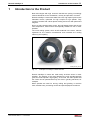
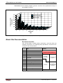


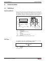
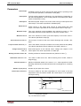
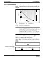

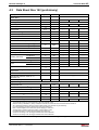
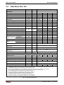
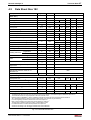
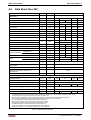
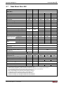

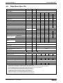
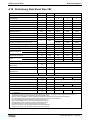

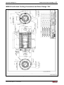
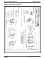
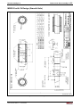
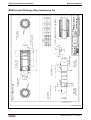
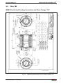
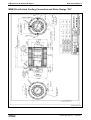
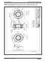
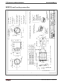
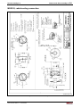
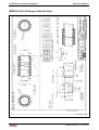
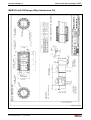

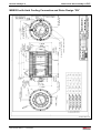
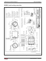
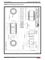
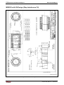
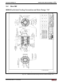
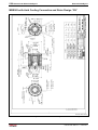
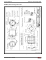
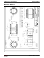
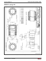
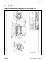
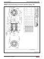
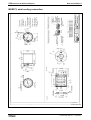
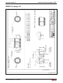
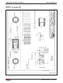
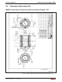
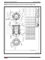
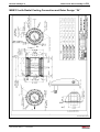
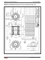
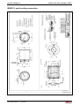
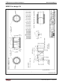
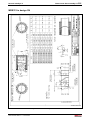
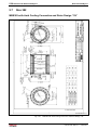

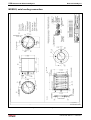
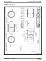
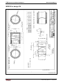
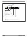
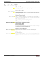
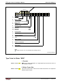

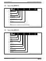
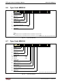
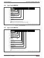
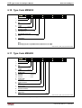
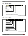
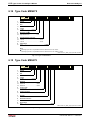
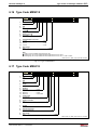

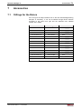

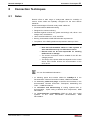
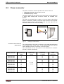
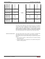
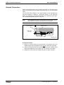
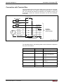
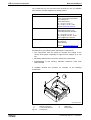
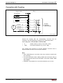
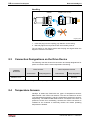
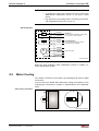
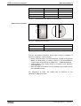

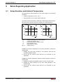

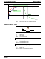
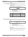
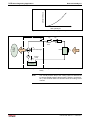
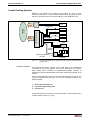
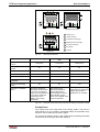
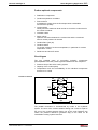
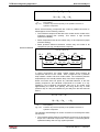

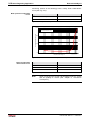
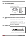
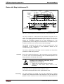
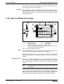


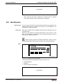
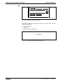

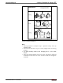
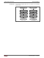

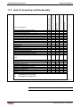
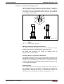
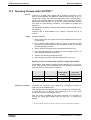
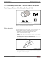
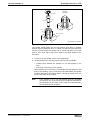
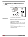
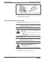
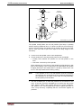
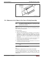
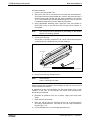
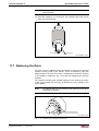
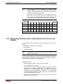
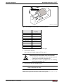
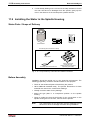
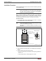
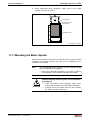
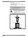
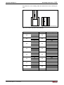
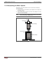
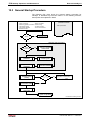
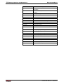
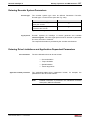
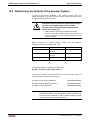
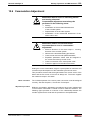
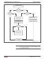
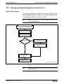
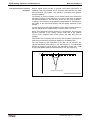


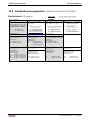
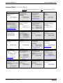
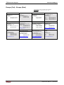
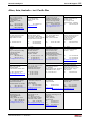


![[Download] azionamenti-hcs01](http://vs1.manualzilla.com/store/data/006141009_1-1242967de3765f3b826dc0b688197751-150x150.png)