1
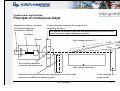
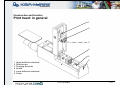
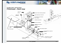
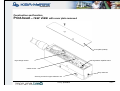
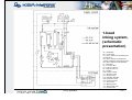
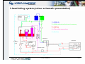
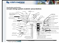
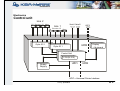
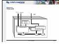
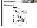
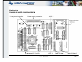
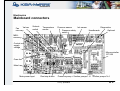
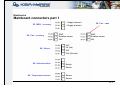
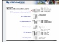
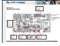
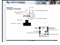
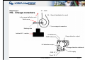
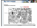
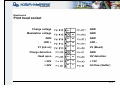
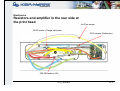
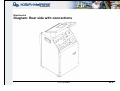
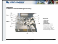
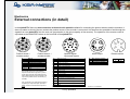
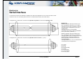
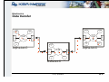
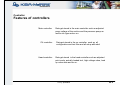
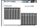
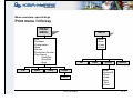
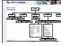
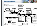
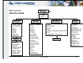
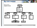
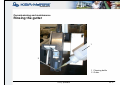
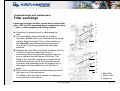
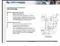
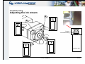
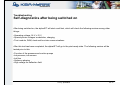
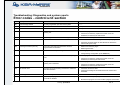
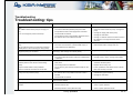
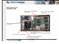
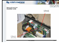
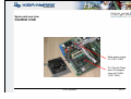
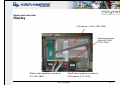
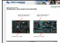
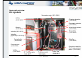
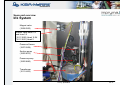
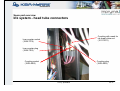
Document issued: March 2008
Manual Tecnico alphaJET C
Compatible con alphajet E
Lista de recambios
Product Manager:
Andres Martos © 2011
alphaJET C Construction and function
Construction and function
Principle of continuous-inkjet
Ink supply
Charge electrode: transmits the charge to the
separating ink drops
The separation of the drops must take place within the charge electrode, because
a drop only can be charged during the separation!
Nozzle
High voltage electrode (+)
x
HVma
HVmin
Point of drop separation
inside the charge electrode
High voltage electrode (-)
Detection electrode: measures test charges sent from the charge
electrode to calibrate the charge moment
Training: alphaJET C
Gutter collecting the
unused drops
Foil 3
HV
0-100 %
Ultrasonic transducer: converts
the electrical signal into
mechanical oscillation.
Construction and function
Print head: in general
1
2
3
4
5
1
2
3
4
5
6
6
Upper deflection electrode
Detection pin
Charging electrode
Nozzle
Lower deflection electrode
Gutter
Training: alphaJET C
Foil 4
Construction and function
Print-head – front view
Valve V1:
Ink on
”Head closed” detecting magnet
Upper deflection electrode
Valve V2:
Bleeding
Counterpart for the head
close magnet
Detection electrode
Charge electrode
Ultrasonic transducer
(hidden)
Nozzle
Magnifying
glass
Flap holding magnet
Valve cover plate
Lower deflection electrode
(ground)
Gutter
Strobo LED: for drop
monitoring
Training: alphaJET C
Hall-Sensor for ”head
closed” recognition
Foil 5
Construction and function
Print-head – rear view with cover plate removed
Cover plate (sealed)
High voltage resistor
Charge detect amplifier board
Inkflow sensor
Drop outlet slot
Securing screws for upper deflection unit
Training: alphaJET C
Foil 6
1-head
inking system,
(schematic
presentation)
01 = Outlet tube
02 = Level switch
D1 = Flow restrictor for measuring the
viscosity time
D2 = Flow restrictor for limiting the
quantity supplied by the pressure pump
D3 = Flow restrictor in the absorber
F1 = Main filter
F2 = Ink return filter
F3 = Filter for valve V3
F4 = Filter for valve V4
F5 = Air filter
IFS = Inkflow sensor
P1 = Pressure pump
P2 = Suction pump
PA = Pulsation absorber
PM = Protection mesh
PS = Pressure sensor
V1 = Ink-on valve
V2 = Bleeding valve
V3 = Solvent-add valve
V4 = Ink-add valve
Training: alphaJET C
Foil 7
2-head
inking system,
(schematic
presentation)
Training: alphaJET C
Foil 8
1-head inking system,(colour schematic presentation)
Solventrecovery
Ink
Solvent
1 = Add ink
2 = Add solvent and solvent recovery
3 = Ink line
Mixtank
4 = Viscosity measuring
5 = Air line
Valve block
Print head
Suctionpump
Pressurepump
Pulsationabsorber
Pressure sensor
Training: alphaJET C
Foil 9
Construction and function
2-head inking system (realistic presentation)
Print-head 2
Print-head 1
Junctions:
print-heads 1 and 2
Outlet
Quick couplings for ink tube,
bleeding and ink return tube
(small), print-head 2
Air filter
Outlet for P2
suction pump
Inlet
Recovery fan
Air outlet
Ink inlet
Recovery with heat-exchanger
and cooling element
Ink outlet/draining tube
(with plug)
PA pulsation absorber
From gutter
Rear panel
From V2
Door (front)
From the solvent-bottle
To valve V4
From the ink-bottle
F3
Solvent-bottle
Ink filter F1
F2
P3 suction pump (head 2)
Ink-bottle
D2
Ink filter F4
P2 suction pump (head 1)
Ink return filter F6 (head 2)
PM
Pressure sensor
Pressure pump P1
Solvent gained
from recovery
Protection mesh (in tube)
Solvent level switch
To valve V3
Inlet from mix tank
Output to solvent-bottle
Air outlet to print-heads
Training: alphaJET C
Outlet (for viscosimeter + draining tube)
Inlet (from suction pumps)
Outlet (for pressure pump)
Viscosity measuring restrictor D1; Viscosimeter inlet
Foil 10
alphaJET C Electronics
Electronics
Control unit
Line 2
PS Enc od er IO Alarm
Serial1 Serial2
Line 1
UPIF 2
PS Enc oder IO Alarm
Opto-IO 2
UPIF2
Opto-IO 1
Display
+ Ke yboard
C ontrol Unit
CPU (Pc104)
UPIF1
PowerSupply
UPIF2
UPIF = Universal Printer Interface
Training: alphaJET C
Foil 12
Electronics
Print unit
Rem ote
RUN/STOP
UPIF
PowerSup ply
Ma inboard
Headboard 1
Hea dboard 2
Head 2
Inksystem
Training: alphaJET C
Head 1
Foil 13
Electronics
Internal connections
Display
KbdFoil
X3
X5
X7 Keyboard
PC104
Keyboard
Ctrl
VGA
X4
Control Unit
X1
Keyboard
X6
Pwr
Supply
Mains
X1
Opto I/O
Line 1
X2
Opto I/O
Line 2
X1
X3
X4
UPIF
200~230V
Headb.
Line1
Heads
X1
X8 : Solven t Switch
X9 : Temperature Se nsor
X1 0: Stirre r
X11: Pressure Pump
X1 2: Pressure Sensor
REMOTE
X4
X4
Power
Run
Stop
X2
X2
Headb.
Line2
115V
External UPIF
UPIF
X2
X1 3:
X1 4:
X1 5:
X1 6:
X1 7:
Suction Pu mp 1
Suction Pu mp 2
Ink Sensors
Suction Pu mp 3
Suction Pu mp 4
X19
Mainboard
X7
X21
X4: Fan MEX Rec.
X5: Fan Case
X18: Diagnostic
Training: alphaJET C
Foil 14
Electronics
Control unit connectors
To keyboard controller
Power supply connector
UPIF 1
Microcontroller
167/168
Keyboard PC 104-CU
Training: alphaJET C
UPIF 2
Opto-I/O line 1
Opto-I/O linie 2
Foil 15
Electronics
Mainboard connectors
Valves
Fan
recovery
Solventswitch
Temperature
sensor
Pressure sensor
Pressure safety
switch
Ink sensor
Diagnostics
Headboards
Optional
MEKrecovery
Control unit
supply
voltage
Microcontroller
167/168
Case fan
Main fuse
Main power input
Run/stop button
Pressure pump + Suction pumps 1+2 Suction pumps 3+4
Training: alphaJET C
Foil 16
Electronics
Mainboard connectors part 1
BK
X3: MEK - recovery
BN
BU
X4: Fan - recovery
WH
RD
X6: Valves
YE
24V
GN
V4 (Ink)
24V
WH
24V (Solvent)
GN
Switch
Switch
WH
X9: Temperature sensor
X5: Fan - case
+ Supply element
GND
Rotation sensor
24V
BN
X8: Solvent switch
- Supply element
GY
Sensor
GY
Sensor
BU
WH
RD
GND
Rotation sensor
24V
Foil 17
Electronics
Mainboard connectors part 2
BU RD
BK
X11: Presure pump, suction pump head 1+2
VT
WH WH
GN YE
PK
GY
X12: Presure sensor
BU RD
X13: Suction pump 3 + 4
X14: Remote input
BK
VT
WH WH
GN YE
PK
GY
VT
X15: Ink sensors
YE
BK OG
BK RD
X16: Safety switch
BK
GN
Training: alphaJET C
PIN#1,#3,#5: Motor PIN#6: Suction pump 2+
PIN#4: Suction pump 1+
PIN#2: Presure pump +
- Presure sensor
+ Presure sensor
PIN#3,#5: Motor PIN#4: Suction pump 3 +
PIN#2: Suction pump 4 +
- Signal input
+ Signal input
PIN#2,#4,#6,#8: GND
PIN#7: Visco up
PIN#5: Visco down
PIN#3: Tank up
PIN#1: Tank down
Outside contact
Middle contact
Foil 18
F8, F10, F11, F12
50mAF (micro)
Ink sensors
1007.3849
Electronics
Mainboard fuses
F2 - 30 V~ Input from
transformator
F3 - Supply Head &
Headboard, connected
over the Main
Controller
F1
2,5AT
(micro)
5V
1007.3852
F2
5A (Glass)
30V ~
1007.3719
F3
2,5AT (micro)
24V (ext)
1007.3852
F4
0,9A (Multifuse)
Presurepump
1007.3862
F5, F6, F7, F9
500mAF (micro)
Suction pumps 1-4
1007.3854
Foil 19
Electronics
X7 - GND
Charge conectors
X6 – Signal (highlighted line end)
to the upper deflection unit
Ferrite core
1 ½ are wrapped meanders
Marking side
Isolated HV - resistor
Signal X6
GND X7
+U Hallsensor
GND Hallsensor
HV detection output
+12V supply
Charge detection elektrode
Carge detection output
Training: alphaJET C
Foil 20
Electronics
X7 - GND
HS - Charge conectors
X6 – Signal (highlighted line end)
to the upper deflection unit
Ferrite core
1 ½ are wrapped meanders
Marking side
Isolated HV - resistor
+U Hallsensor
GND Hallsensor
Carge detection output
HV detection output
Charge detection elektrode
GND X7
+12V supply
Signal X6
Training: alphaJET C
Foil 21
Electronics
Headboard connectors
Diagnostics
Address jumper
Print head
UPIF
Mainboard
Training: alphaJET C
Microcontroller 167/168
Foil 22
Electronics
Print head socket
Charge voltage
GND
GN
Modulation voltage
BK
GND
GND
BK
BK
GND
LED +
BU
OG
LED –
V1 (Ink on)
RD
OG
V2 (Bleed)
BK
GND
Charge detection
Head open
BU
GN
HV detection
+ 24V
WH
YE
+ 12V
+ 24V
BN
VT
Ink flow (Gutter)
Foil 23
Electronics
Resistors and amplifier in the rear side at
the print head
Ink Flow sensor
18 KΩ resitor (Charge electrode)
33 Ω resistor (Hallsensor)
200 MΩ resistor (HV)
Training: alphaJET C
Foil 24
Electronics
Diagram: Rear side with connections
Training: alphaJET C
Foil 25
Electronics
External connections (overview)
8
7
Line 1
3
6
Line 2
5A
Assignments:
8
7
4
6
5B
2
9
10
1: Main supply
2: Main fuse
3: Main switch
4: Remote socket
5A: Print head A connection
5B: Print head B connection
6: Product sensor / encoder
7: Input & output options
8: Alarm-outputs (voltage free)
9: Optional interface (UPIF)
10: RS 232 serial port connector
1
Training: alphaJET C
Foil 26
Electronics
External connections (in detail)
In the alphaJET-C there are two connection sockets wired in parallel available for connecting the product sensors and the encoders. It
does not matter to which of the two sockets the product sensor or the encoder is connected. It is therefore also possible to feed through the
signals from one alphaJET-C into the next one (pay attention to the driver capacity of the sensors). The operation of the remote socket is
equivalent to the RUN/STOP button on the front side of the alphaJET-C.
Product sensor- /
encoder-socket
1
2
3
4
5
6
7
Housing
Product sensor- /
encoder-socket
GND Int.
GND Ext.
Encoder track A (speed)
+ UB Ext. (max. 30 VDC)
+ UB Int. (approx. 24 VDC)
Input Product Sensor
Encoder track B (direction)
Shield
The special input circuit of the machine
requires that the sensor signal of a product
sensor with push-pull output stage (see the
latter’s data sheet) must be connected to the
input of the product sensor via a diode (e.g.
1N4148).
Also the signal for an optional input, which is
supplied by an output with push-pull output
stage, must be connected to the input via a
diode.
Optional signal
inputs and outputs
1
GND Ext. (Outputs)
2
GND Int.
3
GND Ext. (Inputs)
4
Output 0: Line is printing
5
Input 0: *Reset distance (DMS)
6
Output 1: Ink or solvent empty
7
Input 1: Reset print mark divider
8
Output 2: Print ready
9
VCC Ext. (Inputs)
10
VCC Int.
11
VCC Ext. (Outputs)
12
Input 2: *Reset overprint suppressor (OPS)
13
Input 3: Reset product counter
14
Input 4: ExtText - ext. text selection (bit 0);
Textlist - Reset text list
15
Input 5: ExtText - ext. text selection (bit 1);
Textlist - Reset text list with print cancellation
16
Input 6: ExtText - ext. text selection (bit 2)
Housing
Alarm output
1
2
3
4
NC (opening contact)
C (centre contact)
NO (closing contact)
PE
Remote socket
1
2
-IN
+IN
Shield
*In italics = not standard
Training: alphaJET C
Foil 27
Electronics
Serial Interface
For the data connection from alphaJET to alphaJET as well as from alphaJET to PC or to other controls the serial
interface is used. The connecting cable has to be a so-called serial link cable (null modem cable).
Configuration of a cable for the connection from alphaJET to alphaJET as well as from alphaJET to PC:
Background:
While the alphaJET sets the pin RTS (# 7) to
high, the alphaJET reads in the pin CTS (# 8).
If the signal CTS is high, the alphaJET uses the
selected interface configuration (in the menu:
System/Serial).
If the signal CTS is low, the alphaJET
automatically switches the interface parameters
to the ”panic mode” (19200,8,E,1).
Configuration of a cable for the connection from alphaJET to other controls (e. g. PLC):
While the alphaJET sets the pin DTR (# 4) to
high, the alphaJET reads in the pin DSR (# 6).
If the signal DSR is high, the settings in the menu
System/Serial are used with activated ”CU”,
which means that commands are sent to all
connected devices.
If the signal DSR is low, ”CU” is not activated and
”commands-to-all” are suppressed.
Pin 1: DCD
Pin 2: RxD
Pin 3: TxD
Pin 4: DTR (Output)
Pin 5: GND
Pin 6: DSR (Input)
Pin 7: RTS (Output)
Pin 8: CTS (Input)
Training: alphaJET C
Foil 28
Electronics
Data transfer
C
O
M
1
CM
‘A’
C
O
M
1
C
O
M
2
Disk
‘D’
AlphaJet-C
Line2
‘2’
Line1
‘1’
Line2
‘2’
Line1
‘1’
Disk
‘D’
Line1
‘1’
C
O
M
1
C
O
M
2
CM
‘I’
Disk
‘D’
C
O
M
2
CM
‘B’
Term.
‘L’
AlphaJet-C
Term.
‘L’
BetaJet-C
Training: alphaJET C
Foil 29
alphaJET C Controller 168
Controller
Features of controllers
Main controller:
CU controller:
Head controller:
Data get stored in the main controller such as adjusted
pump voltage of the suction and the pressure pump as
well as ink type and so on.
Data get stored in the cu controller such as all
configuration and text files and all setup attitudes!
Data get stored in the head controller such as adjusted
print mode, actually loaded text, high voltage value, load
up value data and so on.
Training: alphaJET C
Foil 31
Controller
Download module “Controller 168”
These listed orders are needed if a not programmed controller get installed in the system of the AJC system.
With this orders you can individually program the controller separate.
call
Declaration
DSP 1 1
With this order the controller is programmed by the head 1 on the headboard!
DSP 1 2
With this order the controller is programmed by the head 2 on the headboard!
DSP 1 3
With this order the controller is programmed by the head 3 on the headboard!
DSP 1 4
With this order the controller is programmed by the head 4 on the headboard!
MC 1 0
With this order the controller is programmed on the main board!
CU167 1 1
With this order the controller is programmed on the 1st head board(head 1)!
CU167 1 2
With this order the controller is programmed on the 2st head board(head 2)!
Training: alphaJET C
Foil 32
Printing speeds
The following printing speeds are possible for a machine with a 55 µm nozzle:
Modulation frequency [Hz]: 87719
Mode
Drops
2.5 mm character width (M7x5)
2.0 mm character width (M7x5)
Vmax
(m/sec)
Vmax
(m/sec)
Vmax
(m/min)
Vmax
(m/min)
Max. print
frequency
1g
25
1.46
87.72
1.17
70.18
3508
1HS
15
2.44
146.20
1.95
116.96
5847
1HS7
10
3.65
219.30
2.92
175.44
8772
1HS5
7
5.22
313.28
4.18
250.63
12531
2g
51
0.72
43.00
0.57
34.40
1719
2HS
31
1.18
70.74
0.94
56.59
2829
2HS14
19
1.92
115.42
1.54
92.34
4617
3g
79
0.46
27.76
0.37
22.21
1110
3HS
47
0.78
46.66
0.62
37.33
1866
The following printing speeds are possible for a machine with a 70 µm nozzle:
Modulation frequency [Hz]: 65146
Mode
Drops
2.5 mm character width (M7x5)
2.0 mm character width (M7x5)
Vmax
(m/sec)
Vmax
(m/sec)
Vmax
(m/min)
Vmax
(m/min)
Max. print
frequency
4g
95
0.38
23.08
0.31
18.47
923
1g
25
1.09
65.15
0.87
52.12
2605
4HS
71
0.51
30.89
0.41
24.71
1235
1HS
15
1.81
108.58
1.45
86.86
4343
5g
122
0.30
17.98
0.24
14.38
719
1HS7
10
2.71
162.87
2.17
130.29
6515
6g
162
0.23
13.54
0.18
10.83
541
1HS5
7
3.88
232.66
3.10
186.13
9307
1 UHS
9
4.06
243.66
3.25
194.93
9746
2g
51
0.53
31.93
0.43
25.55
1277
2 UHS
25
1.46
87.72
1.17
70.18
3508
2HS
31
0.88
52.54
0.70
42.03
2101
2HS14
19
1.43
85.72
1.14
68.57
3429
3g
79
0.34
20.62
0.27
16.49
825
3HS
47
0.58
34.65
0.46
27.72
1386
4g
95
0.29
17.14
0.23
13.71
685
4HS
71
0.38
22.94
0.31
18.35
917
5g
122
0.22
13.35
0.18
10.68
533
6g
162
0.17
10.05
0.13
8.04
402
1 UHS
9
3.02
180.96
2.41
144.77
7238
2 UHS
17
1,60
95,8
1,28
76,64
3832
Training: alphaJET C
Foil 33
Menu overview: special keys
Print menu / Info key
PRINT
MENU
INFO
•Line
•Printlabel
•Configuration
•State
•Service
•Production-Counter
•Free Space
–FlashDisk
–RamDisk
–Ram
OK
Start
Stop
•Line
•Error
•Class
•Code
OK
Count
•Count
Training: alphaJET C
Clear
Errors
Version
•Error
•SystemID
•Class
•Code
•Date
•Time
•Count
Foil 34
Menu overview
Text
Text menu
New
New
OK
Backup
Copy
Copy
Delete
Delete
Restore
OK
Backup
No
Restore
•2/5 interl
•Code 39
•Code 128
•Data Matrix
•Dummy
•EAN-13
•EAN-8
•EAN128
•EAN128C
•Ext2
•Ext5
Edit
Edit
Load
Load
Yes
New
Block
• ITF-14
• ITF-16
• Logo
•Number
•Shift
•UPC-12
•UPC-8
•Time
Format
Move
Copy
Text format:
•Font
•Bottom Up
•B→A
•Negative
•Proportional
•double space
•StrokeWidth
•CharacterWidth
•field index
Ok
Cancel
Grid
In italics = option
Training: alphaJET C
Foil 35
Menu overview
Config
Configuration menu
New
New
OK
Copy
Copy
Backup
Restore
OK
Backup
Delete
Delete
No
Norm
Prog
•Divider
Yes
Restore
OK
OK
Edit
Edit
Install
•Shaft-Encoder
•Resolution
•Tolerance
•Left - Right
•Right - Left
•Direction Inv.
•Printlength
•Density
•Printposition
•BottomUp
Head
•Measured length
In italics = option
IO
•PS
•Progress
•Print Frequency
•Speed
•Capacity used
•Pixel
•Forward
Part 2
•ext_text
•standard
•textlist
Load
Load
ProgPar
•Printstart
•PS signal inverse
•Start only forward
•Printmarkdivider
•Distance in mm
•from EndStart
StartStart
•Flighttime
•OPS
•OffsetY
•OffsetX HeadX
Training: alphaJET C
Foil 36
Menu overview
Service
Service menu
•Inksystem
•Head X
Funct.
Funct.
•Press.-Pump
•Suctionpump
•Ink
•Ready
•Purge
•Bleed
•StabTest
•Clean Noz.
Special
•Add ink
•Add solvent
•First Fill
•Empty system
•Thicken ink
•Wash system
•Empty head
•Wash head
Status
Status
Status Inksystem
•Press.
•Temp
•Visco
•Inklevel
•Filltime
•Ink-Watch
•Visco top
•Visco bottom
•Solvent empty
•Add ink
•Add Solvent
Phasing
Phasing
Setup
Setup
•Head
•Modulation
•Phase
•Bar 1:
Point of changing charge value
•Bar 2:
Separation of the drops
•Printmode
•HV [%]
•Modulation
•IFlowWatch OFF
•Mod-Frequency
•Pressure
•Visco-Offset
•HVMin
•HVMax
•Suctionpump
•InkType
•Nozzle Size
•Heads Line1
•Heads Line2
Status Head X
•Inkflow
•HV [V]
•Ink
•Bleed
•Head open
•Suctionpump
Training: alphaJET C
AutoMod
Foil 37
Menu overview
System
System menu
•LocalSysID
•Language
•EditorHeight
•LabelViewHeight
•DummyFields
Line
•Name
•Device
•LineMerge
Serial
Pass
•ComXActive
•Baudrate
•Parity
•Control Unit
AutoOn
•active
•Basiclicence
•Password 1...4
•Licence
AutoOff
Training: alphaJET C
Time
•Hour
•Minute
•Day
•Month
•Year
All
Foil 38
Menu overview
File menu
File
..
font
logo
•ajc.pmf
•ascii.tbl
•autocfg.ini
•buffer.clp
•comm.exe
•cu.exe
•cu.ini
•cu167.exe
•...
•...
Copy
Delete
Training: alphaJET C
Foil 39
alphaJET C Commissioning and Maintenance
Commissioning and maintenance
Maintenance
Regular maintenance work:
Daily:
Check both storage containers
Clean the head
Weekly:
Clean the machine
Clean and - if necessary - replace the air mat
½-yearly or after 1,500 – 2,000 operating hours
Change the main filter
Change the ink return filter(s)
Carry out an ink exchange
Yearly:
Replace the air filter
Training: alphaJET C
Foil 41
Commissioning and maintenance
Cleaning the print-head
Clean the following components:
1
2
3
4
5
6
1
Upper deflection unit
Detection electrode
Charge electrode
Nozzle
Lower deflection electrode
Gutter
2
3
4
5
6
Ensure that the print-head is dried thoroughly after the cleaning work has been
carried out!
Do not clean the nozzle prior to switching off, so that it then will be blocked by an
ink drop!
Training: alphaJET C
Foil 42
Commissioning and maintenance
Rinsing the gutter
1
2
1 Cleaning bottle
2 Gutter
Training: alphaJET C
Foil 43
Commissioning and maintenance
Filter exchange
Exchange the main ink filter as well as the return filter
after 1,500 to 2,000 operating hours respectively every
½ year - or after emptying the inking system!
Check the ink pressure prior to exchanging the
filter.
You must always ensure that the ink pressure
has been deflated before you interfere with the inking
system. Wait for at least 15 min. (after switching of
the alphaJET) before dismantling a component
from a part of the inking system that was under
pressure.
Separate the main filter by undoing the spigot nuts (3)
on both of the screw connections on the
connecting tubes. Use absorbent paper to remove
any ink remains that still remain in the filter. The
fitting of the new filter component is carried out by
carefully placing the end of the tube in the screw
connector and tightening up the the spigot nuts (3)
afterwards. Use new cable ties to fix the filter in
place.
Return filters can be removed after pulling the end of
the tubes out of the tube spouts.
The fitting of the new filter is carried out analogous
to the removal of the old one.
Training: alphaJET C
3
2
3
3
1
3
3
2
3
3
1
3
2
1 Main filter
2 Return filter
3 Spigot nut
Foil 44
Commissioning and maintenance
Ink exchange
Empty the system (drain off the ink)
Switch off the machine
Take the draining tube (2)
Carefully remove the closing plug (1) and feed
the open end into an empty bottle (at least 1 litre).
Start the machine in SERVICE-mode and then use
the Empty system command in the service-menu.
Re-fit the closing plug to the draining tube.
1
2
Filling the system (First Fill)
Fill the ink-bottle with ink (approx. 0.5 litre)
Close the gutter using the gutter plug
Start the machine in service-mode
Select the First Fill command in the servicemenu. The filling process starts automatically and
stops after approx. 20 minutes. In order to remove
any air remaining in the system, operate the printhead for approx. 15 minutes using the Bleed
service function.
1 Closing plug
2 Draining tube
Training: alphaJET C
Foil 45
Commissioning and maintenance
Switching off for a longer period of time
1. Shutdown time > 4 days:
•Rinse the gutter thoroughly.
•Use the seals provided with the machine to close the gutter and the nozzle.
•Store the machine in an upright position in a cool and dry location.
Re-commissioning:
No special measures required.
2. Shutdown time > 14 days (pigmented inks only with alphaJET disconnected from the mains):
•Whilst the machine is switched off, the ink that remains internally in the viscosimeter will be fed out through the outlet tube.
•Afterwards the viscosimeter must be filled with solvent. Put approximately 20 ml of solvent (by using a plastic pipette bottle) into
the outlet tube.
Re-commissioning:
No special measures required.
Please note: If the alphaJET (for pigmented inks) remains connected to the mains, do not fill the viscosimeter with
solvent as the automatic start-up process is active! (If there was a disconnection from the mains, please switch the
machine on and off, so that the automatic start-up process works properly.)
3. Shutdown time > 4 months (all inks):
•In this case we recommend that the inking system is emptied by using the relevant command in the service-menu.
•Afterwards fill up with solvent (“First fill”).
Re-commissioning:
The solvent remaining internally in the inking system is drained using the “Empty system” command. Afterwards it must be re-filled
with ink again (“First fill”).
Training: alphaJET C
Foil 46
Commissioning and maintenance
Transport
Before an alphaJET-C is transported, always ensure that the machine has been prepared in accordance with
the transport conditions :
When you are sure that the alphaJET-C will be placed in an upright position during the transport, only the
following tasks have to be carried out:
Empty the ink-bottle and close it with an air-tight lid.
Empty the solvent bottle.
Close the suction tube with a plug.
Close the gutter with the gutter plug.
Close the nozzle with the nozzle plug.
If upright transport cannot be guaranteed, then do the following in addition to the above:
Empty the inking system.
Training: alphaJET C
Foil 47
alphaJET C Troubleshooting
Troubleshooting
Adjusting the ink stream
Gutter
Correct
ink stream setting
Aperture slot
Training: alphaJET C
Foil 49
Troubleshooting
Self-diagnostics after being switched on
After being switched on, the alphaJET will start a self-test, which will check the following sectors among other
things:
•Operating voltage: 24 V, ±12 V
•Special printer voltages: modulation, charging
•Test: module, RAM, clock and bus inter-communications
After this test has been completed, the alphaJET will go to the print-ready state. The following sectors will be
tested prior to this:
•Function of the pressure and suction pumps
•Ink pressure, ink sensors
•Ink flow
•Optimum phasing
•High voltage for deflection field
Training: alphaJET C
Foil 50
Troubleshooting: Diagnostics and system reports
Error codes - control unit section
No.
Description
Cause
Elimination
001
Event-Manager started
Is always registered upon start of the system.
–––––
100
PU–Reset
Main board controller defective.
•
Replace the main board.
101
Encoder Detection Error
The encoder supplies clock pulses to phase B only
•
Replace the encoder.
102
Communication Error UPIF
Incorrect transmission between the control unit and
printing unit.
•
Check the plug connections.
•
Check and, if necessary, replace the control unit or the
headboard, if necessary the main board.
103
Format File Error
The configuration to be loaded is no longer available.
•
Load a different configuration and check the values.
104
Label File Error
The text to be loaded is not available.
•
Load a different text. When using the “ExtText” print program
•
Check the connected inputs for text selection as well as the
reference list (Text-Load).
Too many fonts and logos have been stored or
logo/font files are defective.
•
Delete all unnecessary logos.
•
Delete logo/font files.
Print label exceeds print storage.
•
Redesign (reduce) print image.
•
Change storage configuration (in file sbsize.ini).
The serial transmission between control and printing
unit.
•
Check plug connectors.
•
Check and, if necessary, replace the control unit or the
headboard, if necessary the main board.
The print data transmission between control and
printing unit is disturbed.
•
Check plug connectors.
•
Check and, if necessary, replace the control unit or the
headboard, if necessary the main board.
An error has occurred during transmission of data via
the serial interface.
•
Check the connection cable .
•
Compare the settings of the serial interface for receiver and
transmitter.
105
106
107
108
109
Fonts/logos loaded in part only
Print buffer in a too small
UPIF/Serial transmission error
UPIF/DMA transmission error
File transfer error
110
MPL-Program failed to be loaded
The MPL-Program to be loaded is not available.
•
Load a different MPL-Program and check the values.
112
MPL-runtime error
The MPL print program selected is defective. The print
controller is disabled.
•
Load a different MPL print program.
•
Eliminate the program error from the MPL program and reload it.
Training: alphaJET C
Foil 51
Troubleshooting: Diagnostics and system reports
Error codes - control unit section
No.
Description
Cause
Elimination
113
Communication Error: Unknown
command
The command received is unknown.
•
Electromagnetic disturbances.
•
Non-Compatible program versions.
114
Loading error: System setting
An initialization file for the system configuration is
defective or missing.
•
Check and, if necessary, correct all settings in the system
configuration and restart.
115
Insufficient main memory
The available main memory is insufficient.
•
Check the memory setting. Switch AJC off and on again.
116
No RAM-Disk
No RAM-Disk was found.
•
Wrong CU version (PC version on AJC or AJC version on PC).
•
RAM-Disk (CU167) defective.
•
Delete files (texts, configurations).
•
RAM-Disk (CU167) defective.
117
Insufficient unassigned RAM-Diskmemory
There are too many files on the RAM-Disk.
118
Loading error: specific printer
parameter
Configuration file (specific printer parameters)
defective or missing.
•
Check and, if necessary, correct all settings in the service field.
120
Not compatible terminal version
Terminal (PC) software and printer software are
incompatible with each other.
•
Update the software.
121
Unknown MPL command
MPL version and printer software incompatible with
each other or MPL program defective.
•
Update the software.
•
Correct the MPL-program .
600
Print stop
No longer ready for printing.
•
Re-establish readiness for printing.
601
Auto stop
The counter of the Auto stop function has elapsed.
•
Reactivate or deactivate the counter function.
602
Print during printing
Printing is triggered during a printing process.
•
Check of the application (Product sensor signal).
Training: alphaJET C
Foil 52
Troubleshooting: Diagnostics and system reports
Error codes - printer section
No.
Description
Cause
Elimination
200
"Ink tank empty”"
Ink level below a value of 50.
•
Refill the ink bottle .
•
Check the ink adding valve (V4).
•
Refill the solvent bottle.
•
Check the solvent adding valve (V3).
•
No error, if the ink has been replaced only a short time before.
•
Check the solvent adding valve (V3).
•
Check the pressure pump (P1).
•
Check the sieve (positioned before P1).
•
Check the pressure sensor and the cable.
Communication with the real-time clock defective
(applicable to pigmented ink only).
•
Hardware error .
•
Call the customer service.
Mirrored system data and parameters stored in the
printing unit are lost.
•
Check all parameters in the Service/Setup window and readjust
them.
This error occurs whenever the controller MC167 on
the main board has been replaced.
•
Call the customer service.
Serial communication between the control unit and the
printing unit defective.
•
Check the UPIF cable (40 pins).
•
Call the customer service if this error occurs repeatedly.
•
Let a little ink flow out.
•
Check the flow restrictor.
•
Check the ink electrodes.
The ink level has reached the upper ink electrode.
•
Check all of the ink electrode connections.
Valve V3 or V4 defective.
•
Check valve V3, V4.
Filltime deviation at least 12 seconds.
•
Add solvent.
"Add solvent" warning has been neglected; V3
defective.
•
Check V3.
201
202
203
204
205
206
"Solvent empty”
"Viscosity Warning\+\–50”
Ink pressure out of range
RTC Warning
"Data lost”
"Communication
Warning\UPIF\PFO;Error Data”
Solvent bottle empty.
Fill time deviation at least 5 seconds.
Ink pressure too high / too low by at least 12%.
Intense radiated interference.
207
"Timeout: Filltime”
Upper viscosity electrode without ink for at least 10
minutes.
Mixtank overfilled.
Flow restrictor D1 blocked.
Electrode not connected.
208
209
"Ink tank full \ error”
"Viscosity out of range”
Training: alphaJET C
Foil 53
Troubleshooting: Diagnostics and system reports
Error codes - printer section
No.
Description
Cause
Elimination
210
"Fan Error\MEK”
Cooling air blower for solvent defective or too slow.
•
Check the cable.
•
If necessary, replace the blower.
•
Check the cable.
•
If necessary, replace the blower.
211
"Fan Error\AJ”
Main cooling air blower defective or too slow.
212
"MEK power failure”
Supply voltage applied to the solvent recovery unit
defective.
•
Check the connector or replace the unit.
213
"Temperature sensor error”
Ink temperature sensor defective or not connected.
•
Check the sensor and the cable, or replace the sensor.
214
"Overpressure switch !”
Ink pressure protective switch released.
•
Replace the ink filter.
Ink filter clogged.
•
Clean / replace D3.
Flow restrictor D3 blocked.
215
"Pressure sensor error”
No pressure sensor detected.
•
Check the sensor and the cable.
216
"Supply Voltage Error”
One of the operating voltages (+12 VDC, –12 VDC,
+24 VDC, solvent recovery unit) is incorrect.
•
Check the fuse F3.
•
Call the customer service.
Ink level in the mixtank too low; sieve before the
pressure pump clogged.
•
Check the ink level; clean the sieve; check the pressure pump, if
necessary, replace it.
218
"Debit pressure not attainable"
Pressure pump defective.
219
Pressure pump defective
Autodiagnosis: pressure pump or main board
defective
•
Check and if necessary, replace the pressure pump.
•
Call the customer service.
220
Suction pump defective
Autodiagnosis: suction pump error.
•
Check and if necessary, replace the suction pump.
•
Call the customer service.
Check the ribbon cable connection between main board and
head board.
221
MC / FPGA Transmission error
Autodiagnosis: error in transmission between main
board and FPGA.
•
•
Call the customer service.
222
DSP transmission error
Autodiagnosis: error in transmission between main
board and DSP.
•
Check the ribbon cable connection between main board and
head board.
•
Call the customer service .
223
Headboard Configuration
The configured head board failed to be detected.
Training: alphaJET C
•
Check the configuration (ServiceSetup)
•
Call the customer service
Foil 54
Troubleshooting: Diagnostics and system reports
Error codes - printer section
No.
Description
Cause
Elimination
224
Suction pump supply defective
Main board electronics for suction pump(s) defective.
•
Check the fuses F5, F6, F7, F9.
•
Call the customer service.
Encoder frequency exceeded maximum value.
•
Check the speed of the belt conveyor.
Belt conveyor running too quickly, or encoder
defective.
•
Check the encoder.
Incorrect modulation voltage.
•
Check the modulation voltage.
Ink too old.
•
Check / clean the charge detect sensor.
Wrong or missing drop build-up.
•
Check the charge detect signal.
Charge detect signal too weak (charge detector
board).
•
Replace the ink.
•
Replace the load detector board or the head board.
250
251
"ENC-Frequency too high”
"Automatic phasing not possible”
252
"Error Modulation Voltage”
Incorrect modulation voltage.
•
Replace the head board.
253
"Charge Voltage error”
Charging voltage incorrect.
•
Replace the head board.
254
DSP / FPGA transmission error
Error in transmission from DSP to FPGA (head board)
•
Replace the head board.
255
UPIF transmission error (PU)
Data transmission between control unit and DSP
defective.
•
Check the ribbon cable connection between control unit and
head board.
•
Call the customer service.
High voltage too low.
•
Check the print head or dirt.
Value for HVmax too high.
•
Check the HV cable and the electrode insulation.
High-voltage flashover.
•
Clean the print head.
Print head dirty.
•
Check / reduce the HV value.
•
Clean the nozzle.
•
Replace the ink.
•
Check the settings in the Service / Setup window (in the
supervisor mode).
258
259
"HV value out of range”
"Error Deflection Field”
Value for HVmax too high.
260
262
"Ink Flow missing”
"Head Board Error”
Ink jet missed gutter; ink too old.
More print heads have been configured than are
actually available.
Training: alphaJET C
Foil 55
Troubleshooting
Troubleshooting: tips
Determined problem
Possible reason
Repair
The voltage at the pressure pump is too high (> 8
volts).
The audible rotation of the pump is too high (>2
rps).
1.
The diaphragm inside the pressure pump is defective.
1.
Change the pump.
2.
The valves inside the pressure pump are soiled.
2.
3.
The protection mesh in the supply tube is blocked.
Clean the valves inside the pump / change the
pump.
No or not enough ink pressure is built up.
4.
The main filter is blocked.
3.
Change the supply tube of the pump.
5.
The protection mesh in the pulsation absorber inlet or
the restrictor D3 in the outlet are blocked.
4.
Change the main filter.
5.
Change or clean the mesh in the left connector /
the restrictor in the right connector of the
absorber.
The voltage at the pressure pump is too low (<5
volts).
1.
The flow restrictor D2 is partly or totally blocked.
1.
Renew flow restrictor D2 completely.
2.
The ink is much too thick. ( Solvent bottle empty or
solvent add valve V3 defective.)
2.
Refill solvent bottle / change valve V3.
The ink pressure varies. The viscosity measuring
possibly doesn´t work correctly (too long cycles).
No or an apparently wrong viscosity measuring
though the pump rpm is normal.
The visco-measuring restrictor D1 is partly or totally
blocked (e.g. after a longer shut down period).
Change visco-measuring restrictor D1.
Insufficient / varying suction at the gutter.
1.
The ink return filter is soiled
1.
Change ink return filter.
2.
The valves inside the suction pump are contaminated
or defective.
2.
Change pump or clean / change valve plates.
Recovered solvent gets into the printhead.
1.
. Drain the air filter +
Restless position of the XX’es in the Phasing
display.
The machine was operated with horizontally orientated
back panel.
2.
The cooling element is defective.
Frequent contamination of the printhead.
3.
An ink with very low viscosity has been filled into the
system.
1.
The protection mesh in the pulsation absorber inlet /
the restrictor D3 in the pulsation absorber outlet is
blocked.
2.
The main filter is blocked.
Solvent is visible at the bottom of the air filter.
Visible interferences on the inkstream (pulsations
coming from the pressure pump).
1.
Assemble the back panel.
2.
Replace the recovery unit.
3.
Leave opened the lower bleed screw of the air
filter until viscosity is normal
1.
Change / clean the mesh (left connector) or the
restrictor D3 (right connector).
2.
Change the main filter.
Viscosity never reaches value 0.
Solvent add Valve V3 doesn’t close correctly. Permanent
minimal solvent addition.
Change V3.
Varying ink pressure / pressure safety switch
releases.
1.
Blocked main filter F1.
1.
Replace main filter.
2.
Blocked restrictor D3.
2.
Clean / replace restrictor.
3.
Blocked protection mesh (absorber inlet).
3.
Clean / replace protection mesh.
Training: alphaJET C
Foil 56
alphaJET C Spare part overview
Spare part overview
Control Unit
Ribbon cable COM2 DSUB9
(1007.3245)
Ribbon cable COM 1 DSUB9
(1007.3246)
Modul 168 programmed for CU
(1011.4791)
Fan Contronl Unit (1011.3333)
LCD activ adapter board Ribbon cable COM 1
(1011.4893)
Ribbon cable PC104 keyboard to
CU mainboard (1007.3255)
Training: alphaJET C
Foil 58
Spare part overview
Control Unit
I/O Board B
(1011.4778)
I/O Board A
(1011.4773)
Training: alphaJET C
Foil 59
Spare part overview
Control Unit
Main power supply
CU (1011.4782)
PC 104 with Flash
and LCD adapter
since AJC 5894
(1007.1292)
Training: alphaJET C
Foil 60
Spare part overview
Display
LCD display ¼ VGA (1007.1692)
Keyboard contoller
since AJC 5894
(1011.4788)
Ribbon cable keyboard controller to
CU (1011.2985)
Ribon cable keyboard controller to
LCD adapter (1011.3010)
Training: alphaJET C
Foil 61
Spare part overview
Headboard, main board and controller
Module 168 programmed for
Headboard (1011.4792)
Headboard (1011.5056)
Module 168 programmed for
Mainboard (1011.4793)
Mainboard (1011.5046)
Training: alphaJET C
Foil 62
Spare part overview
Ink system
Pneumatic mesh (1011.0426)
Airfilter
(1010.3547)
Pulsation absorber
(1010.2579)
Pneumatic restrictor
(1011.0427)
Mixtank
(1010.9327)
Valve block comlete
(1011.0183)
Solventfilter
(1010.3542)
Inkbottle(1010.2233)
Inkbottlepigmentet(1010.2234)
Solventbottle
(1010.9340)
Mainfilter
(1010.3535)
Flow restrictor
(1010.6353)
Inkfilter
(1010.3543)
Protection mesh for
diaphragm pressure
pump (1010.8826)
90 °Coupling plug
(1006.4907)
Coupling socket
(1006.4905)
Training: alphaJET C
Union-Tee
(1008.6961)
Foil 63
Spare part overview
Ink System
Magnet valve
(1008.6505)
Ribbon cable head 1/2
and lines 1/2
(1011.3050) Head 1L2H
(1011.3051) Head 2
Pressure Sensor
(1007.5209)
Suction pump
(1000.9876)
Pressure pump
(1000.9885)
Transformer
(1011.6463)
Training: alphaJET C
Foil 64
Spare part overview
Ink system - head tube connectors
Coupling with mesh for
ink supply tube red
(1011.0411)
Luer coupler socket
(1008.7278)
Luer coupler plug
(1008.7303)
Coupling socket
(1006.4905)
Coupling plug
(1006.4906)
Training: alphaJET C
Foil 65
You create, we print……