1
BACK PANEL
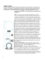
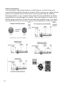
All the connections on this page our found on the back panel of the mixer
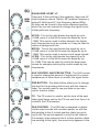
PHANTOM POWER switch
This switch activates and deactivates the Phantom power on all the microphone inputs. Most condenser microphones require phantom power, which is
a lower DC voltage delivered to the XLR microphone connector.
MAIN OUTPUT 6.35mm (¼") SOCKETS
These ¼" output sockets provide balanced or unbalanced line-level signals.
This is the same signal that appears at the XLR’s main outputs, (except the
¼" jacks are unaffected by the main output level switch. Connect these to the
next device in the signal chain like an external processor, or directly to the
input of the main amplifier.
MAIN OUTPUT XLR SOCKETS
Connect directly from the mixer directly to the speakers. Gain can be adjusted
using the main mixers controls. Use none powered speakers and dedicated
speaker cable. Connect one speaker to the left XLR and one speaker to the
right XLR connections.
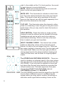
CHANNEL INSERTS 1-4
These unbalanced ¼" Jacks are for connecting serial effects processors such
as compressor, equalizer, de-esses, filters ect. The insert point is after the gain
control, and the low cut filter, but before the channel’s EQ and level. The channel signal can go out of the insert jack to an external device, be processed and
come back in via the same jack plug.
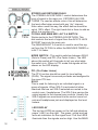
ALT 3-4 OUTPUTS
The ALT 3-4 outputs are unbalanced and carry the signals from all the channels that you have muted. This can be used to send a group of signals to a
further mixing console, or it could be used as a recording output in tandem
with the main output.. This means you could record to four tracks all at the
same time.
CONTROL ROOM OUTPUTS
The control room outputs normally connected to a monitor system in the control room and provides the stereo mix or, when required, the solo signal.
IEC MAINS INLET with fuse
For connecting to the mains outlet plate via an IEC lead
5