1
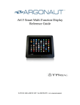
G615XLR Marine Monitor
Reference Guide
Tel 858 456 8550 or 800 967 4287 · Fax 858 454 9224 · www.argonautcomputer.com
TABLE OF CONTENTS
Mounting, Wiring, Care
Pages 1-3
Button Controls
Pages 4-9
Technical Support FAQ
Page 10
Support, Repair, Service Policy
Pages 11-14
Specifications
Page 18
Getting Started and Care
Your Argonaut G615XLR monitor has been engineered for trouble-free use in the marine environment.
Please retain this reference guide for relevant installation, wiring, care information, and operation
adjustment (Button Controls).
Surface Mounting
The G615XLR monitor has been designed for an easy, secure and sealed installation. For surface mount
installations, please note the following steps:
1) Locate a suitable installation mounting surface. The surface should be flat and allow at least
enough room for the outside bezel face to fit (14.45” x 11.70” W x H). Note that the thickness of
the display is 1.35” so make sure there is enough clearance to mount in your desired
location. Make sure there is sufficient clearance behind the surface for cabling passage (.75”
minimum recommended). Rear surface space should also allow clearance to install mounting
screws from the rear; however, the display can be installed without using mounting screws, if
necessary.
2) Once mounting location is identified, carefully align the mounting template to the surface in the
exact location desired and secure lightly with tape. Mark the centers of the 4 outer corner holes.
Mark the connector clamp bracket outline and outside edge of the template. Once all holes
are marked, surface may be drilled and cut accordingly.
3) Monitor can now be seated against the surface. In some installations, a bead of marine caulking
may be desired to help prevent any water intrusion to the mounting surface openings. This bead
of caulking/adhesive can be placed upon the outer edge of the back cover and may also be
sufficient to secure the monitor in place without screwing into the enclosure from behind the
surface. Take care not to allow sealant to penetrate the gap between the front bezel and rear cover
as this may prevent opening the monitor if service is ever needed. Another approach is to lay down
a thin layer of weather stripping flush to the monitor edge. This strip can be sealed at the edges
with caulking. In general, after positioning/sealing is complete, screw monitor down to surface
(Note: screw type is M4 x 12 stainless steel machine thread and 4 screws are provided). A
different length screw may be required depending on bulkhead thickness. In all installations,
where water contact can occur with the display, caulking sealant should be placed around the
screw and connector clamp bracket openings. Once secured to the surface, take care not to over
tighten mounting screws.
Optional RAM Mount Kit
The RAM mount kit includes adapter plate, surface base, swivel arm and monitor mounting base plate.
Secure square monitor mounting base plate to adapter plate using four stainless steel 10/32 x ½” flat head
screws, flat washers and lock nuts provided (Note: RAM logo should be oriented in same direction as
RAM decal on adapter plate) . Attach adapter plate to back of monitor using four stainless steel M4 x 12
pan head screws with flat washers and split washers provided (orientation: screw, split washer, small flat
washer, large flat washer). Tighten Securely. Attach surface base to mounting location. Secure monitor
with swivel arm to surface.
Quick-start Instructions
1.)
2.)
3.)
4.)
The Power cable should be connected as described above.
Connect the signal input cables to signal output devices (for example PC, camera, black box, etc.).
Press the power (Button 7) to turn on the monitor. The Power indicator will light up.
Press input signal source hotkey (Button 5) to display related input signal.
Wiring
NOTE: THE POSITIVE WIRE IS RED AND THE NEGATIVE IS BLACK.
The standard cables include VGA, DVI, RCA/S-Video, and DC Power cable. All cables exit the rear of the
monitor through a waterproof cable clamp. Note that the input cable ends are not waterproof and
should be placed or installed in a dry, protected area. DO NOT PULL CABLES TIGHT IN ORDER
TO PREVENT EXCESS STRAIN AND POSSIBLE BREAK IN CABLE CLAMP SEAL. Contact
your Argonaut Dealer if additional cable lengths are required in excess of standard provided.
Power
The G615XLR monitor is designed for 12 Volt power input through an Argonaut supplied power regulator.
The correct regulator is specified at time of ordering for connection to either a 12 volt or 24 volt system.
The regulators accept a range of voltage (either 9 to 18V or 19 to 32V) and provide a steady 12 volts to the
monitor.
NOTE: ANY DIRECT CONNECTION OF THE MONITOR TO 12 OR 24 VOLT
POWER WITHOUT FIRST RUNNING THROUGH THE ARGONAUT SUPPLIED REGULATOR
COULD PERMANENTLY DAMAGE THE MONITOR AND VOID YOUR WARRANTY. DO
NOT CONNECT THE REGULATOR TO VOLTAGE EXCEEDING THE SPECIFIED RANGE AS
THIS WILL DAMAGE THE REGULATOR. DO NOT CONNECT THE MONITOR DIRECTLY
TO A/C POWER (110-220V) POWER AS THIS WILL DAMAGE THE DISPLAY AND COULD
CAUSE A FIRE. PLEASE MAKE SURE TO AVOID IMPROPER CROSSING WIRES
(POSITIVE TO NEGATIVE) AS THIS CAN DAMAGE THE DISPLAY ELECTRONICS
Care & Precautions
Care: The LCD has a special coating to prevent reflection. Clean with soft clean cloth or cotton and
alcohol. Commercially available “Kensington Screen Guardian” for antiglare screens is highly
recommended. If water has collected in screen bezel, wipe dry before covering/storing. NOTE: DO NOT
ALLOW SALT WATER DEPOSITS TO REMAIN ON GLASS SURFACE FOR EXTENDED
PERIODS (REMOVE SALT DEPOSITS WITH FRESH WATER). LONG TERM SALT
DEPOSITS MAY CAUSE PERMANENT DAMAGE TO THE SCREEN SURFACE. Additional
Precautions: Do not operate in temperature extremes (below 32°F (0° C) or above 104 °F (40° C)). Do
not put pressure or contact directly on screen surface. Do not connect directly to power source
without using the regulator supplied. Do not reverse power wires. Do not expose to submersion or
high pressure water. Do not pull or strain cabling as this can break the cable clamp seal.
Button Control Summary
2. Down (Auto)
1. Menu
3. Decrease
1
2
3
4
5
Menu
Down (Auto)
Decrease
Increase
Source/Exit
6
Power LED
4. Increase
6. Power LED
5. Source Hotkey/Exit
7. Power
Menu Key
Down Key (HOT Key: Auto Config.)
Decrease Key, Left Key
Increase Key, Right Key
Source Select & Exit HOT Key: Source Select
[Analog – DVI ]
Amber: Monitor off in standby mode
7
Power
Flashing Amber: Seeking input signal
Green: Monitor on with input signal
Power On/Off
Note: Your Argonaut G615XLR marine monitor has been preset at the factory for optimal viewing
either inside or under direct sunshine. For most usage the power button, Dimming control buttons
and signal input hotkey are the primary items that may require adjustment. In the event settings
have been changed and you wish to restore the factory defaults, please follow the instructions to
RESET the monitor to factory defaults found later in this section.
The OSD (On Screen Display) menu controls the monitor image and settings.
Input Source
A RGB - Change input signal source to Analog RGB.
DVI - Change input signal source to DVI.
S-Video - Change input signal source to S-video.
Composite - Change input signal source to composite video.
Exit - Go Exit back to main menu.
Picture
Brightness - Adjust Brightness of the screen.
Contrast - Ratio of luminance between black and white. Adjust distinction.
Blacklevel - Adjust black level.
Sharpness - Adjust Sharpness of pictures.
Hue (video only) - Adjust between green tone and purple tone.
Saturation (video only) - Adjust color intensity.
Exit - Go back to main menu.
Color
Temperature
Choice of: User, Warm, Normal, and Cool – RGB can be adjusted.
User: Able to adjust the color by controlling Red, Green, and Blue.
Warm: Red-tinged screen.
Normal: Green-tinged screen.
Cool: Blue-tinged screen.
Auto Color (A-RGB Only) - Color automatically set for input signal.
Exit - Go back to main menu.
Image Control
Available Mode – Analog RGB
Auto - Auto configuration of geometry.
Width - Adjust horizontal size of the screen by increasing or decreasing the number of
picture elements.
Phase - Adjust Phase of screen. Used when noise or overlapped lines are shown on the
screen.
H Position - Move screen horizontally.
V Position – Move screen vertically.
Exit - Go back to main menu.
Tool
OSD Control Time Out: The range of controlling the duration time of the OSD menu (OSD turn-off
time).
H Position: Adjust horizontal position of OSD Menu by value.
V Position: Adjust vertical position of OSD Menu by value.
Reset - Initial set-up, preset by the factory before forwarding.
Reset Color - Initial color.
Reset Position (A RGB Only) - Initial position.
Exit - Go back to main menu.
Troubleshooting
Problem & Question
Power LED is not on
No Plug & Play
Picture is Fuzzy
Picture bounces or wave
pattern is present in the
picture
The Power LED is
ON(Amber) but there’s no
video or no picture
Discolored Image (RED,
GREEN, or BLUE)
Possible Solution
*Confirm power supply output.
*Check power connection.
*Check if the PC System is Plug & Play
compatible
*Check if the Video Card is Plug & Play
compatible
*Press Reset in OSD.
*Move electrical devices that may cause
electrical interference.
*Verify input signal.
*Make sure cables are properly
connected.
* Inspect input cables for damage.
*Confirm the input source is operational
by connecting a separate monitor to the
source.
* Inspect the monitor’s video or DVI
cable and make sure that none of the pins
are bent or corroded.
Screen image is not
centered or sized properly.
* Press Reset Position in OSD.
Picture has color defects
(white does not look white)
Horizontal or vertical
disturbances on the screen
Image is dim
* Press Reset Color in OSD.
Monitor Turns Off
* Confirm minimum voltage to regulator.
* Press Reset in OSD.
* Adjust brightness control.
ARGONAUT G615XLR TWO YEAR PARTS AND LABOR WARRANTY
This warranty covers the Argonaut Computer G615XLR marine display. The warranty period is two years
from the date of the original purchase invoice. If you think your Argonaut product needs repair, please
check with the Reseller you purchased your Argonaut from to determine if it needs repair as well as where
to get it repaired as described below. Argonaut Computer will provide parts and labor repair on the product
to correct manufacturing defects in material or workmanship. Factory installed components are covered by
this warranty. Components installed by the Reseller are not covered by this Argonaut Computer warranty.
Therefore, always call your Reseller first to determine the coverage.
Warranty Repair Procedure
In the event your product needs service, please contact your Reseller first to determine the nature of the
problem and relevant warranty coverage. The customer should provide the serial number, date of purchase,
and Argonaut Computer or the reseller’s invoice number. A Return Merchandise Authorization (RMA)
number will be issued to you, the customer with packaging and shipping instructions. This RMA number
must appear on all packages shipped to Argonaut Computer Service Center (Note: any shipment sent to
the service center without a clearly marked RMA number may be refused.). The customer must
clearly specify the address where the product is to be returned, (to ensure prompt handling, please provide
the return shipping address on a separate sheet within the package). Please note the return address may not
be a PO Box and the telephone number must be provided. Repaired product should be inspected
immediately upon receipt for damage caused by shipper. If shipping damage has occurred, please retain
shipping packaging and contact Argonaut within 5 days of receipt in order to ensure a proper damage claim
filing. Argonaut Computer, Inc. is not liable for any shipping damage claims placed later than 5 days from
receipt. NOTE WARRANTY EXPIRATION IS TWO YEARS FROM ORIGINAL INVOICE DATE
AND RMA PRODUCT MUST BE RECEIVED BY ARGONAUT PRIOR TO EXPIRATION EVEN
IF AN RMA NUMBER WAS OBTAINED IN ADVANCE OF THE EXPIRATION DATE.
Out of Warranty Repair Procedure
If it is determined that the failed part is not covered by Argonaut Computer, or is out of warranty, Argonaut
Computer will assess the standard parts cost and a repair rate that is authorized by the customer or return
the product without repair upon request.
Freight
All products sent to Argonaut Computer for warranty repair must be shipped to our service center freight
prepaid. Argonaut Computer will pay the domestic ground shipping within the 48 continental states back
to the customer. The Customer is required to pay freight back on all non-domestic shipments.
NOTE: Parts removed from repaired products are owned by Argonaut Computer. Warranty on repaired
product is not extended past the original warranty expiration date. Opening the casing to your Argonaut
product will void this warranty.
This Warranty covers normal use. This Warranty does not warrant or cover (Check with Argonaut
Computer for complete details):
• Damage caused by direct contact with high pressure water or other corrosive liquids or solvents.
• Damage to LCD glass or A/R coating including long term exposure to salt deposits. Salt deposits
should be cleaned with fresh water periodically.
• Damage, cracks, bubbles or black circles on glass or liquid crystal.
• Damage caused by submersion.
• Damage caused by a disaster such as fire, flood, wind, earthquake, lightning, or other acts of God.
• Damage caused by unauthorized attachments, alterations, modifications, or foreign objects.
• Damage caused by peripherals.
• Damage caused by improper electrical connection (reverse polarity) or excess power surges.
• Damage caused by improper installation.
• Damage caused by excessive cable strain or pulling including water damage caused as a result of
broken cable seals.
• Damage caused by any other abuse, misuse, mishandling or misapplication.
• Damage caused by extended operation in direct sunlight at temperatures above 95°F.
• Damage caused by operation at freezing temperatures below 32° F.
ARGONAUT COMPUTER, INC., ITS SUPPLIERS AND AUTHORIZED DEALERS
(VARS/VADS) ARE NOT LIABLE FOR ANY DAMAGES, INCLUDING ANY LOST PROFITS,
LOST SAVINGS, OR OTHER INCIDENTAL OR CONSEQUENTIAL DAMAGES ARISING OUT
OF THE USE OR INABILITY TO USE SUCH PRODUCT EVEN IF ARGONAUT, ITS
AUTHORIZED DEALERS OR ITS SUPPLIERS HAVE BEEN ADVISED OF THE POSSIBILITY
OF SUCH DAMAGES. ALL IMPLIED WARRANTIES WITH RESPECT TO ANY OF THE
ENCLOSED,
INCLUDING
WITHOUT
LIMITATION,
WARRANTIES
OR
MERCHANTABILITY, FITNESS FOR A PARTICULAR PURPOSE, AND NONINFRINGEMENT, ARE LIMITED IN DURATION
Customer Support & Repair Service Policy
Every Argonaut product comes with support and repair service features. Argonaut Computer, Inc.
has designed a Customer Support and Repair Services Policy to provide these services to its valued
customers. The following sections detail each service as they relate to Argonaut hardware and
software products.
Technical Support
All technical support requests for Argonaut products shall be submitted to the attention of "Technical Support" via
telephone - (951) 813-3600, fax - (858) 454-9224, or email - [email protected]. Customer must
provide Technical Support with a model and serial number to best assist the customer's needs. Technical Support reserves
the right to determine the scope of warranty coverage.
Proof of Warranty
The customer shall provide an invoice number, date of purchase, and the product model and serial number
to verify proof of warranty. Argonaut Computer, Inc. has a database which Technical Support may access
to retrieve customer invoice information; however, customer must provide the product model and serial
number to verify authenticity. Customer should also inform Technical Support of whether he/she
purchased the product independently or through a dealer to direct the appropriate database search.
Technical Support for Hardware
Technical support for diagnosing problems with hardware on Argonaut products will be provided within
the limited warranty term. The standard limited warranty term is one year, unless an extended warranty is
purchased. Following the warranty term, hardware support will be provided for a fee, which will be
charged to the customer's credit card, on a per-incident basis.
In-Warranty Repairs
To request repair services on your Argonaut product within the warranty period, customer must contact
Technical Support to determine the nature of the problem and relevant coverage. In the event customer's
Argonaut product needs service, a Return Material Authorization (RMA) number will be assigned and
instructions for shipment to our Service Center will be provided. Please note all RMA shipments to our
Service Center must be prepaid. We will pay the domestic ground shipping within the 48 continental states
back to you. Customer will be required to pay freight back on all shipments to Alaska, Hawaii or
international locations. Any shipments to our Service Center without an RMA will be refused. Any RMA
sent to the wrong address (other than explicitly specified in the RMA instructions) will incur a premium
overnight charge at the expense of the customer, and could delay repair services up to 1 week for rerouting.
Minimum lead-time for all in-warranty repairs is 2 weeks.
NOTE: Parts removed from repaired products are owned by Argonaut Computer, Inc. Warranty is not
extended on repaired product.
Out-of-Warranty Repairs
To request repair services on a known out-of-warranty Argonaut product or if customer is uncertain of
warranty coverage, customer must contact Technical Support to determine the nature of the problem and
relevant warranty coverage. In the event customer's Argonaut product needs out-of-warranty service, an
Out-of-Warranty Return Material Authorization (RMA) number will be assigned and instructions for
shipment to the Service Center will be provided. Please note all Out-of-Warranty RMA shipments to our
Service Center must be prepaid. Any shipments to our Service Center without an RMA will be refused.
Any RMA sent to the wrong address (other than explicitly specified in the RMA instructions) will incur a
premium overnight charge at the expense of the customer, and could delay repair services up to 1 week for
rerouting. Customer will be charged an inspection and evaluation fee for all Out-of-Warranties RMA
products shipped to our Service Center. Upon customer's authorization to proceed with repairs, the
inspection and evaluation fee will be applied to overall repair charges (new product and/or parts not
included). Customer will be required to pay freight on all Out-of-Warranty RMA returns whether repairs
are made or not. Argonaut Computer, Inc. cannot guarantee availability of parts needed for repair services,
especially on out-of-production products or components. A limited warranty shall be provided for Out-ofWarranty repair parts. Minimum lead-time for all out-of-warranty repairs is 4-6 weeks.
NOTE: Parts removed from repaired products are owned by Argonaut Computer, Inc. Warranty is not
extended on repaired product.
We understand that occasionally a product must be returned. That is why products purchased directly from
Argonaut Computer, Inc. Come with a return policy. Our policy is clearly stated. Please take the time to
read it now before using your new product.
PLEASE NOTE: THIS RETURN POLICY ONLY APPLIES TO DIRECT SALES FROM
ARGONAUT COMPUTER, INC. TO END-USER CUSTOMERS.
IF PRODUCTS ARE
PURCHASED FROM AN ARGONAUT AUTHORIZED DEALER, THAT DEALER'S RETURN
POLICY WOULD APPLY.
Important Notice about Argonaut Computer, Inc. Return Policy
When opening your package DO NOT DISCARD ANYTHING - you will need it in the event of a return!
RETURN POLICY
Before returning any item, we require that you first call for a Return Merchandise Authorization (RMA)
number. Your purchase must be returned freight prepaid and insured for its full purchase value. Returns
must include the original invoice and be in "as new" resalable condition, in its original packaging with all
registration cards, documentation, media, and all other materials enclosed.
Returned merchandise must be received back in our warehouse within 10 days of the original invoice and
shipment date. We will not accept returns sent COD, returns sent without an RMA, or returns that arrive
past the 10-day period. Shipping charges are not refundable. A restocking fee of up to 15% of your
original purchase value may be charged for testing, reinstallation of operating system/drivers, and
packaging replacement. Customer may not return any preinstalled, open-packaged, or customer- registered
marine and/or other software, and will be charged current retail list pricing. A 25% restocking fee, based
upon current retail list pricing, will be charged for software returned in sealed packaging “as new
“condition. Additional charges may result from missing components or physical/electrical damage to the
computer case or electronics. Defective product returned within the 10-day period will not incur a
restocking fee but customer may be charged for missing components or damage. Processing returns can be
complicated. Please allow 10-14 days after receipt of product to process your credit.
To request a Return Merchandise Authorization (RMA) number, call (951) 813-3600 during normal
business hours. Be sure to have your original invoice in hand before calling. Detailed return shipping
instructions will be provided to you by fax or email.
Notes
Rugged Features
Enclosure/Finish
Shock/Vibration Mount
LCD
Connectors
Aluminum/Gray Powder Coated
All Internal Components, LCD Mil-Spec Shock
Mounted
Optically Bonded Antireflective Glass, Optional
Touch Screen
Stainless Steel, Sealed Connector Cable Clamp
General Features
Display Type
TFT Active Matrix Tflex™ LCD; VIS: 15” (38.1 cm),
Diagonal; Optically Bonded, Sunlight Readable
Display Area
304mm x 228mm
Sunlight Brightness [1]
1200+ cd/m2¹
Ambient Backlight Brightness
450 cd/m2 (typ)
Response Time
Viewing Angle
16ms (typ)
Horizontal: 120 Degrees; Vertical: 100 Degrees
Compatibility
Scanning Frequency
VESA,UXGA, SXGA, XGA, SVGA, VGA; Mac®
Equipped with VGA Port
Horizontal: 30K~63KHz; Vertical: 55~75Hz
Pixel Frequency
80MHz
Maximum Resolution
Auto Scaling Up To UXGA Input, Native Resolution
1024x768@75Hz
16 Million
Color
Signal Input
Connectors
Power Source
User Control OSD Function
Video: 0.7V;-p, RBG Analog; Separate Sync: TTL
Level; H/V Sync: Positive/Negative, RCA Composite
Video, DVI
Standard VGA,DVI, RCA and S-Video, Power,
Waterproof Sealed Cable Clamp, Optional Touch
Screen USB Interface
12/24 V DC (11-16V or 19-36VInput)
Language Supported
Brightness (Dim To Black), Auto Adjust, Power,
Menu, 2 Menu Select/Adjust for Multiple OSD
Adjustments/Functions. Optional Touch Screen.
English, French & Spanish
Operating Temperature
0°C to +50°C
Water/Corrosion Resistance
NEMA 4X, Internal VCI Corrosion Protection
Dimensions (WxHxD)
Weight
Mounting Options
14.45” (367.03mm) x 11.70 (267.18mm) x 1.27
(32.26mm)
7lbs (Includes cabling)
Surface Mount, RAM Mount Kit (optional)
Options/Accessories
Easy Pass VGA Extension Cabling 15’. 25’ or 40’.
[1] Brightness equivalent in Direct sun. The specifications and pictures are subject to
change without notice.
All brand names are registered trademarks of their respective owners.