1
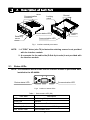
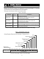
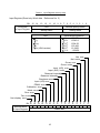
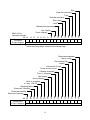
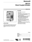
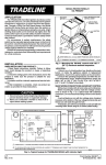
AD-4408A Weighing Indicator for Modbus-RTU Interface AX-ABCC-MODBUS INSTRUCTION MANUAL 1WMPD4001975 WARNING DEFINITIONS The warnings described in this manual have the following meanings: A potentially hazardous situation which, if not avoided, could result in death or serious injury. A potentially hazardous situation which, if not avoided, may result in minor or moderate injury or damage to the instrument. This symbol indicates caution against electrical shock. Do not touch the part where the symbol is placed. This symbol indicates the ground terminal. This symbol indicates that an operation is prohibited. NOTE Information or cautions to use the device correctly. © 2009 A&D Company, Limited. All rights reserved. No part of this publication may be reproduced, transmitted, transcribed, or translated into any language in any form by any means without the written permission of A&D Company, Limited. The contents of this manual and the specifications of the instrument covered by this manual are subject to change for improvement without notice. Modbus is a registered trademark of Modicon, Incorporated. Anybus-CompactCom is a registered trademark of HMS Industrial Networks. TORX is a registered trademark of Textron Inc. Contents 1. Introduction...................................................................................................................2 2. Description of Each Part ...............................................................................................3 2.1. Status LEDs ........................................................................................................3 2.2. Communication Connector..................................................................................4 3. Installation ....................................................................................................................5 3.1. Interface Module Installation ...............................................................................5 3.2. Connections and Functions.................................................................................6 3.2.1. Cable Connections..........................................................................................6 3.2.2. Setting the Functions ......................................................................................7 4. Modbus Memory...........................................................................................................9 4.1. Memory Map .......................................................................................................9 4.2. Handling Bits Directly ........................................................................................13 4.2.1. Handling Command Bits ...............................................................................13 4.2.2. Command bit execution procedure ...............................................................13 5. Timing Chart ...............................................................................................................14 6. Errors..........................................................................................................................15 6.1. Error Types .......................................................................................................15 7. Check Mode ...............................................................................................................16 7.1. Checking the Modbus-RTU Communication Status ..........................................16 7.1.1. Entering the Check Mode..............................................................................16 1 1. Introduction The AD-4408A functions as a slave device of Modbus (RTU) when the Modbus-RTU interface module (AX-ABCC-MODBUS) is installed. A signal level can be selected either for RS-232 or RS-485. Data communication using Modbus can be performed by pre-mapped memory operation. Thus, programming communication protocol is not required. NOTE: Memory map and check modes vary with the interface module installed. This manual describes performances when the Modbus-RTU interface module is installed. When other modules are installed, refer to the relevant instruction manual. Instruction manuals for each interface module are available on our website. 2 2. Description of Each Part NOTE 2 Communication connector Locking catch Ground Locking catch Device status LED NOTE 1 Retaining screw Communication LED Fig.1 Interface module part names NOTE: 1. A TORX® driver (size T9) to fasten the retaining screws is not provided with the interface module. 2. A connector for the cable side (D-Sub 9-pin male) is not provided with the interface module. 2.1. Status LEDs NOTE: The illustration below shows how the interface module is positioned when installed to the AD-4408A. 6 Device status LED 9 1 5 Communication LED Fig.2 Position of status LEDs Table 1 Device status LED (DS) LED state Description OFF Initializing / No power Green ON Normal Red ON Hardware malfunction Red, single flash Communication error / Setting error Red, double flash Recoverable error 3 Table 2 Communication LED (COM) LED state 2.2. Description OFF Offline / No power Yellow ON Online (Normal) Red ON Communication error Communication Connector NOTE: The illustration below shows how the interface module is positioned when installed to the AD-4408A. 6 9 Communication connector 1 5 Fig.3 Connector pin assignment Functions for each pin are as follows. Table 3 Communication connector Pin No. Signal Description Housing SHIELD 1 SG Signal ground 2 5V Not used Shield (Connected to the AD-4408A FG terminal) Selects the signal level. RS-232: Connect to pin 2. RS-485: Leave pin 3 disconnected 3 PMC 4 __ 5 B (+) 6 __ 7 RX RS-232 RxD 8 TX RS-232 TxD 9 A (-) RS-485 A line (Negative side) __ RS-485 B line (Positive side) __ By pin connections, a signal level can be selected either for RS-232 or RS-485. 4 3. Installation 3.1. Interface Module Installation Be sure to disconnect the AD-4408A from the power source before installing the interface module. Install the interface module as follows: Blank panel Step 1 Using a Phillips screwdriver, loosen the screws that secure the blank panel to the AD-4408A rear panel, and remove the blank panel. Step 1 Step 2 Step 2 Insert the interface module into the option slot as shown to the right. Step 3 Insert the interface module until it mates with the terminals of the PC board connector located in the option slot. Option slot Retaining screw Interface module PC board in the option slot Step 4 Using a TORX® driver (size T9), fasten the retaining screws with a tightening torque of 0.25 Nm in the clockwise direction to secure the interface module. Step 3 Tightening torque 0.25 Nm Step 4 Fig.4 Interface module installation NOTE: A TORX® driver is not provided with the interface module. 5 3.2 . Connections and Functions 3.2.1. Cable Connections By connector pin connections, a signal level can be selected either for RS-232 or RS-485. When the signal level is RS-485, add a terminator to both ends of the network. Place a terminator between A and B as shown in the figure below. The A-B terminals of the host device may be reversed, depending on the device type. When the host device has no SG terminal, an SG connection is not necessary. When the cable is to be shielded, connect the cable shield to the connector housing. Terminator 100-120Ω 1/2W Host device A B SG FG Some host devices may have a terminator built in. The A-B terminals of the host device may be reversed, depending on the device type. A B SG Housing (FG) AD-4408A No.1 Use a twisted pair cable for a signal line. Use a shielded cable as necessary. A B SG Housing (FG) AD-4408A No.2 A B SG Housing (FG) Place a terminator on the device located furthest from the host device. AD-4408A No.31 Fig.5 Terminator 100Ω 1/2W Example of RS-485 multidrop connection 6 3.2.2. Setting the Functions The functions described here are general functions. General functions are divided into groups per function and are indicated by the group name followed with the function number, FXX. NOTE: General functions determine the AD-4408A performance and all of the settings are stored in the FRAM. Setting Procedure Step 1 While pressing and holding the ENTER key, press the F key. fnc is displayed to indicate that the indicator will enter the general function mode. Step 2 Press the ENTER key. The indicator enters the general function mode. To go back to the weighing mode without entering the general function mode, press the ESC key. Step 3 Press the ∧ or ∨ key to select the function group to be set. Display Group name Modbus-related functions rtuf Press the ENTER key. The function number will be displayed. Function No. Function Description Default value rtuf01 Station No. 1 rtuf02 Baud rate rtuf03 Parity 1 to 247: Station No. 1: 1200 bps 2: 2400 bps 3: 4800 bps 4: 9600 bps 5: 19200 bps 6: 38400 bps 7: 57600 bps 8: 76800 bps 9: 115200 bps 0: None 1: Odd 2: Even 5 2 NOTE: Data bits are fixed to 8 bits and stop bit is fixed to 1 bit. Step 4 Press the ∧ or ∨ key to select the function number to be set. Press the ENTER key. The current setting value will be displayed. 7 Step 5 Change the setting value using either one of the methods below. Method Selecting a parameter Inputting the value Description Only the parameter number to be selected is displayed and blinks. Press the ∧ or ∨ key to select a parameter. All the digits are displayed and a digit to be changed blinks. Press the < or > key to select a digit and press the ∧ or ∨ key to change the value. After setting, press the ENTER key. The next function number is displayed. When the parameter is not to be changed, press the ESC key to return to the function number display. Step 6 Press the ESC key. The function number disappears and the indicator returns to the state of step 3. Press the ESC key to store the setting values in the FRAM and go back to the weighing mode. NOTE: The blinking decimal point indicates that the current value is not the weight value. If a value exceeding the settable range is entered, err dt is displayed and the input is canceled. 8 4. Modbus Memory 4.1. Memory Map Modbus uses reference numbers and addresses to control the AD-4408A or to read data. The AD-4408A uses Holding Registers and Input Registers. Data types and reference numbers are as shown below. Table 4 Data type Data types Reference No. Description Read and write bit data Output Coil 0 Corresponds to the input of the control I/O. Not used for the AD-4408A. Read only bit data Input Status 1 Corresponds to the output of the control I/O. Not used for the AD-4408A. Read only Word data Input Register 3 Used to read weight values and command responses. Read and write Word data Holding Register 4 Used to send commands. NOTE: Do not access the memory area that the AD-4408A is not using. Table 5 Holding Register memory map Holding Register (Read and write Word data Reference No. 4) Zero Clear the zero value Tare Clear the tare value Error reset Hold* Manual print command Net display Gross display Bits 9-15 are internally reserved. Bit 15 14 13 12 11 10 First word of Holding Register 9 8 7 6 5 4 Command bits *Hold at the rising edge, release at the falling edge 9 3 2 1 0 Table 6 Input Register (Read only Word data Bit First word of Input Register Input Register memory map Reference No. 3) 15 14 13 12 11 10 9 8 7 6 5 4 3 2 1 0 Unit Decimal point position Setting value Setting value Unit Decimal point position 0: None 123456 1: 101 12345.6 2 2: 10 1234.56 3 3: 10 123.456 4: 104 12.3456 5 5: 10 1.23456 0: None 1: g 2: kg 3: t 4: lb (USA version) Net over Net under Gross over Gross under Input (A/D) over Input (A/D) under Reserved internally Reserved internally Checksum error Input (A/D) error FRAM error Calibration error Mode error Zero error Tare error Net display error Bit 15 14 13 12 11 10 Second word of Input Register 9 8 7 Status bits 10 6 5 4 3 2 1 0 Zero Clear the zero value Tare Clear the tare value Error reset Hold* Manual print command Net display Gross display Bits 9-15 are internally reserved. Bit 15 14 13 12 11 10 Third word of Input Register 9 8 7 6 5 4 3 2 1 0 1 0 Command response *Hold at the rising edge, release at the falling edge Slave normal operation Slave ready Error status flag Stable Net center of zero Gross center of zero Capacity exceeded Tare in progress Net display Gross display Hold in progress In sync with Weighing failure Reserved internally Reserved internally Reserved internally Bit 15 14 13 12 11 10 Fourth word of Input Register 9 8 7 Status bits 11 6 5 4 3 2 Bit Fifth word of Input Register Bit Sixth word of Input Register Bit Seventh word of Input Register Bit Eighth word of Input Register Bit Ninth word of Input Register Bit Tenth word of Input Register 15 14 13 12 11 10 9 8 7 6 5 4 3 2 1 0 3 2 1 0 3 2 1 0 3 2 1 0 3 2 1 0 3 2 1 0 Net weight Weight value (Low order word) 15 14 13 12 11 10 9 8 7 6 5 4 Net weight Weight value (High order word) 15 14 13 12 11 10 9 8 7 6 5 4 Gross weight Weight value (Low order word) 15 14 13 12 11 10 9 8 7 6 5 4 Gross weight Weight value (High order word) 15 14 13 12 11 10 9 8 7 6 5 4 Tare Weight value (Low order word) 15 14 13 12 11 10 9 8 7 6 5 4 Tare Weight value (High order word) 12 4.2. Handling Bits Directly 4.2.1. Handling Command Bits A command bit is in the first word of the Holding Register. A command response is in the third word of the Input Register. To execute, turn the corresponding command bit ON. The command bit will be effective at the rising edge. The signal level must be maintained for 30 msec minimum. Table 7 First word of Holding Register and third word of Input Register Command bits Bit 0 Bit 1 Bit 2 Bit 3 Bit 4 Bit 5 Bit 6 Bit 7 Bit 8 Command bit and action Zero Clear the zero value Tare Clear the tare value Error reset Hold Manual print command Net display Gross display 4.2.2. Command bit execution procedure Step 1 The master device turns OFF all the command bits. Step 2 The master device turns ON the command bit to be executed. Step 3 The AD-4408A executes the command and turns ON the corresponding command response. Step 4 The master device confirms the command response and turns OFF all the command bits. 13 5. Timing Chart Slave Normal Operation Slave normal operation is a signal to confirm that the AD-4408A is connected to the power and is in normal operating conditions. During normal operation, the signal is reversed at a 0.5 to 1 second interval. Slave normal operation 0.5 to 1 sec Fig.6 Slave normal operation signal Error status flag If an AD-4408A error has occurred, the slave ready bit will be turned OFF and the error status flag will be turned ON to convey to the master device that an error has occurred. The master device will turn the error reset flag ON to request resetting the error status flag. Error status flag Error reset flag Slave ready Fig.7 Table 8 Resetting the error status flag Command bits / Status bits Memory First word of Holding Register Fourth word of Input Register Description Bit 4 Error reset flag Bit 0 Slave normal operation Bit 1 Slave ready Bit 2 Error status flag 14 6. Errors 6.1. Error Types Error Status Flag This conveys to the master device that an error has occurred. Turn the error reset flag ON to request resetting the error status flag. Table 9 Error status flag Error type Causes Checksum error Program checksum does not match. Input (A/D) error Data can not be acquired from the A/D converter. FRAM error Data can not be written into the FRAM. Calibration error Calibration data is not correct. Mode error Moved to a mode other than the weighing mode. Weighing Failure This conveys a weighing failure to the master device. This will be reset when normal weighing has resumed. Table 10 Weighing failure Error type Causes Zero error Zero adjustment is not performed. Tare error Tare is not performed. Net display error A net value is not displayed. Capacity exceeded The weighing capacity has been exceeded. Capacity Exceeded This conveys to the master device that the weighing capacity has been exceeded. This will be reset when all the errors are cleared. Table 11 Capacity exceeded Error type Causes Net over The net weight is over the net weight range. Net under The net weight is below the net weight range. Gross over The gross weight is over the gross weight range. Gross under The gross weight is below the gross weight range. A/D over A/D value is over the A/D value range. A/D under A/D value is below the A/D value range. 15 7. Check Mode 7.1. Checking the Modbus-RTU Communication Status 7.1.1. Entering the Check Mode Step 1 While pressing and holding the ENTER key, press the F key. fnc is displayed to indicate that the indicator will enter the general function mode. To go back to the weighing mode, press the ESC key. Step 2 While pressing and holding the ZERO key, press the ENTER key. 1Chc is displayed to indicate that the indicator will enter the check mode. Press the ENTER key again to display an item to be checked. Step 3 Press the ∧ or ∨ key to select Chcrtu (Modbus check mode) and press the ENTER key to enter the Modbus check mode. To exit from the check mode, press the ESC key. Table 12 Check mode list Display Chckey Chc Cl Chc∗∗∗ Chcrtu Chc∗∗∗ Chc r5 Chc ad Chc in Chcpr9 Chc 5n C5 pr9 C5 fra Calfdt Checking item Key switches Standard serial output Interfaces Modbus-RTU Testing terminal A/D (Load cell) Internal count Program version Serial number Program checksum Memory (FRAM) checksum Calibration-related functions 16 Checking the Communication Status Press the ∧ or ∨ key to change addresses. Two digits: address (01, 11 to 1A) Four digits: data (0000 to FFFF) 8 8.8 8 8 8 □ □ □ □ □ □ Slave error Slave ready ブ デ Slave normal operation Interface error Interface wait Interface active Address Data type Word 01 Holding Register 1 11 to 1A Input Register 1 to 10 17 MEMO 18 MEMO 19 MEMO 20