1
Pyramix 4.3
www.merging.com
www.merging.com
USER MANUAL
No part of this documentation may reproduced in any form whatsoever or be stored in
any data retrieval system without prior written permission of the copyright owners.
This documentation is supplied on an as-is basis. Information contained within this
documentation is subject to change at any time without notice and must not be relied
upon.
All company and product names are ™ or Registered Trademarks ® of their respective
owners. Windows XP, Windows 2000 and Windows NT are trademarks of Microsoft
Corporation.
Merging Technologies makes no warranties express or implied regarding this software,
its quality, performance, merchantability or fitness for a particular purpose. The software is supplied “as is” you, the purchaser, are assuming the entire risk of the results
of using this Merging Technologies software.
In no circumstances will Merging Technologies, its owners, directors, officers, employees or agents be liable to you for any consequential, incidental or indirect loss or damages including loss of time, loss of business, loss of profits, loss of data or similar
resulting from the use of or inability to use the Merging Technologies hardware and or
software or for any defect in the hardware software or documentation.
© Copyright Merging Technologies Inc. 2004. All rights reserved
Merging Technologies
Le Verney 1070 Puidoux Switzerland
Tel: +41 21 946 04 44 • Fax: +41 21 946 04 45
www.merging.com
User Manual : Contents
User Manual : Contents
3
Thank you!
Pyramix Versions
Pyramix Native
Native Playback Channels
Pyramix LE
Pyramix Virtual Studio Core
Introduction
Conventions
Pyramix Guides
Installation Guide
Virtual Transport Guide
Pyramix Applications Guides
Guides for Pyramix Optional Features
Pyramix Virtual Studio Overview
Pyramix Card and Software Set and Pyramix Turnkey
Pyramix Virtual Studio Board I/O
Time Code and Video Sync Option
System Requirements For Pyramix Virtual Studio
Digital Audio Synchronization and TimeCode
Installing Pyramix Virtual Studio Hardware
Mykerinos Board Installation
Multi-board installation
Daughter-cards
External Audio D/A-A/D Converter Boxes
Cabling Pyramix in your System Environment
Installing Pyramix Virtual Studio Software
Driver Signing
Running the Installer
Enabling Pyramix Virtual Studio with your Software Key
Pyramix User Interface
Mouse Modifier Keys
Context Menus
Keyboard Shortcuts
Macros
Tutorial Project
Project Templates
Pyramix Concepts
14
15
15
16
16
16
17
17
18
18
18
18
18
19
19
19
20
20
22
23
23
23
23
23
24
26
26
26
27
28
28
28
28
28
28
29
30
User Manual : Contents
4
Project
Mixer
Compositions
Timeline
EDL
Media Files
Master Clips
Clips
Media Management - Housekeeping
Media Drives and Folders
Libraries
User Libraries
Automation in libraries
Global Libraries
Offline / Reference Libraries
Sound Effects / Large Projects and Offline Libraries
Project Libraries
Library Maintenance
Track and Mixer Muting
TimeCode Entry
Starting Pyramix Virtual Studio
Beginning a New Project
New Project from scratch
Mixer Wizard
Getting Audio into Pyramix Virtual Studio
Check Sync
Pyramix audio file format
Recording Audio into a Pyramix Virtual Studio Project
Track Record Modes
After Recording
AutoPunch Mode
Importing Audio Files into Pyramix Virtual Studio
Practical Media Management and Libraries
Clips and Compositions
Media Folders
Editing
Clips and Compositions
30
30
30
30
30
30
30
31
31
31
31
31
31
31
32
32
33
33
33
34
36
37
38
41
44
44
45
45
45
45
46
47
49
49
49
52
52
User Manual : Contents
5
Anatomy of a Clip
Locking Clips
Grouping Clips
Gain WIndow
Clip and Selection Editing
Selections and Region Selections
Dragging Clips into a Composition
Copy and Paste
Auto-Crossfade By Default
Clip Fade Commands
Editing Modes
Splitting Clips and Regions
Jog-Wheel Editing
Edit Command highlights:
Auto Silence Removal
The Placement Tool
Markers or User Flags
Using the Mixer
Mixer Components
Creating and Configuring Mixers
I/O Busses Explained
Internal Return Busses
Mixer Delay Compensation
Input Strips
Groups
Mixing/Monitoring/Aux Buses
Configuring a Blank or Existing Mixer
Mixer Configure Mode
Adding Strips
Mixer I/O Assignments
Adding Plug-ins
Further Mixer Configuration Options
Dithering
Channel Direct Outputs
Storing and Recalling Mixer Presets
Mixer Surround Components
Configuration - Program and Project Settings Windows
52
54
54
54
54
55
56
56
58
58
59
59
60
60
63
65
66
67
67
69
69
69
69
70
70
71
73
74
74
74
74
75
76
77
77
78
81
User Manual : Contents
6
General Settings
General
Editing
Playback
Layout
Locations
Time Code
Jog / Chase
Video
Keys
Machines
Controllers
Virtual Transport
Project Information & Settings
Information
Record
Controllers
Mixer Settings
General
I/O and Sync
Mykerinos Daughter Card Settings
Level Meter
Pyramix Virtual Studio Window Orientation
Program Window
Project Window
Dual Monitors
Project Editing Panel
Project Management Panel
Tracks
Adding and Deleting Tracks
Track Header Panel
Navigation
Jog / Shuttle
Transport Controls
Transport Control Panel
Zooming and Panning
Scroll Wheel
82
82
84
86
88
90
91
94
98
99
100
103
104
106
106
107
111
112
112
114
116
116
119
119
120
120
120
121
122
122
123
126
127
128
131
131
132
User Manual : Contents
7
The Overview
Project Management Panel Tabs
Overview
EDL
Document Libraries
Media Management
Tracks
Track Groups
Playlists
Work Spaces
Selection
Fade Editor
Markers
CD
Notes
Machines
Global Libraries
Cue Sequencer
External Machines
9-pin (Sony P2 protocol)
Setting up an external machine
Virtual Multi-track
Digitizing Sessions
Manual Digitizing
Autoconforming
Conforming and Reconforming
Importing a CMX EDL
CMX EDL Format
CMX Autoconform
CMX Reconform
Source - Destination Editing
Concept
Setting up a Source - Destination environment
Automation
Automation Modes
Automation Settings
Selecting Automation Modes
133
134
134
134
135
141
149
152
154
154
154
158
164
165
172
173
173
173
174
174
174
175
177
178
178
180
180
182
184
184
188
188
188
192
192
193
194
User Manual : Contents
8
Master Automation Controls
Display and Editing of Automation Data
Undo/Redo
Editing Automation data
Automation in editing and libraries
Mixer and Plug-in Snapshots
Virtual Transport
What is Virtual Transport?
Strip and Bus Tools - Plug-ins
Eq, Comp/Limiter/Expander
Bus Tools
Delay Compensation
Delay Compensation / Pre-Anticipation
Plug-Ins
Common Master Section
Parametric EQ.
10 Bands EQ
Three Band Tone Control
Dynamics Processing
Delay
Flanger
MS Encoder
AnguDion
Mastering Peak/Vu Meters
Phase-Oscillo
Surround Meter
DC Meter
Modulometer
Function Generator
Plug-in Automation
Effects Snapshots
Optional Plug-ins
Prosoniq MPEX2 Timestretch and pitch change
VST / DirectX support
Direct X Plug-ins
VST Plug-ins
External Effects
195
196
198
198
199
199
201
201
202
202
212
214
217
218
218
220
221
221
222
224
225
226
226
228
234
236
237
237
239
240
240
241
241
244
244
244
245
User Manual : Contents
9
Mastering a Composition to CD-R
CD Markers
Project Processes
Dither
Mixing Down Projects
Exporting Projects to CD Image Files
DiscWrite
Optical Drives - Important Note:
CD Text
Burning a CD-R
Archiving Projects
Consolidating Projects
Converting Projects
Changing Project Length / Pitch
Reconforming a Project
Surround Post-Processing Projects
Rendering Projects
Currently Available Plug-ins
Cleaning Up Project media
Project Interchange
File Interchange with Apple Macintosh
AAF
Akai DD / DR
CD Import
CMX EDL
OMF
ProTools
Report Printer
Cue Sheet Printer
Customizing the User Interface
Interface Editor
Workspaces
Customizing Keyboard Shortcuts
User Macros
Application Specific Configurations
Multitrack Editing
LTC sync
246
246
247
247
247
248
249
252
252
252
254
254
256
256
256
256
257
258
258
259
259
260
262
263
265
265
265
268
268
272
272
273
274
275
276
276
276
User Manual : Contents
10
Dubbing Mode
Virtual Tape Mode
Discontinuous TimeCode
Metronome / Click Track
Menus - Project Menu
Menus - Edit menu
Menus - View Menu
Menus - Clips
Menus - Tracks
Menus - Cursors and marks
Menus - Selection
Menus - Fade Editor
Menus - Automation
Menus - Workspaces
Menus - Machines
Menus - Macro
Menus - Settings
Menus - Window
Menus - Help
Remote Control
Control of External Device
Control by External Device
Hardware Control Surfaces
GPI / GPO Support
Optimizing Pyramix
Use Templates
Pyramix File Format .PMF
One File Per Track option
DSP optimization
Troubleshooting
Keeping Up To Date
Error Messages
Multi-channel Audio Files
No Sound on Live Inputs
Clip Display Problems
Relaunch After Improper Exit
The I/O Status window
277
277
280
281
283
286
292
296
301
303
307
309
313
314
315
320
320
320
321
322
322
322
322
324
326
326
326
326
326
328
328
328
329
330
331
332
333
User Manual : Contents
11
Input sources
Debug Menu
Appendix I Mouse Modifier Keys
Main Editor
Overview
Notes
Media Folder
Appendix II I/O Daughter-card Options
Appendix III Optional Features
Pyramix DSD / SACD
Time-code Sync
Cue Sequencer
Appendix IV 9 - Pin connection
PC RS-232 Serial Port to External Sony P2 RS-422 Controller
Connecting an RS422 device using a direct cable
Appendix V Mykerinos Latencies
Index
333
333
336
336
338
338
338
339
341
341
342
342
344
344
344
346
347
User Manual : Contents
12
User Manual
www.merging.com
USER MANUAL
User Manual : Thank you!
Thank you!
Congratulations on your purchase of Pyramix Virtual Studio. More than just a product, this is a gateway to the future of sound recording, editing, mixing and mastering. You have joined a worldwide community of users who have already discovered the Pyramix advantage.
Note: IMPORTANT! - The first thing you need to do is register your software to
acquire your Pyramix key(s) and to be included in our user support list.
Please also subscribe to the User Forum at:
http://www.merging.com/forum/
User Manual
14
User Manual : Pyramix Versions
Pyramix Versions
There are now several versions of Pyramix. Pyramix Native, Pyramix Native Media Bundle, Pyramix LE
and Pyramix Virtual Studio. Numerous options and option packs are also available. This manual covers
all versions of Pyramix and many optional functionalities and features.
Note: Depending on the version and options purchased, some of the functions and
features detailed in this manual may, or may not, be available in your version of Pyramix, or may vary in capacity.
Pyramix Native
Pyramix Native offers 100% compatibility with the main Pyramix Virtual Studio (VS) system. Both the
Pyramix Native and the Pyramix VS can be connected on the same standard Ethernet network and
directly interchange audio and video media, or a complete Pyramix project between them.The Native
software is USB dongle protected and runs on Windows 2000 or Windows XP desk-top or lap-top computers. It does have restrictions compared to the main Pyr amix Virtual Studio capabilities as you would
expect but the Native software maintains all the real-time editing capabilities expected of a professional
system.
Pyramix native media Bundle Includes Native
Pyramix native includes…
configuration PLUS…
• Tone Control,
• 8 Audible Internal Editing Tracks
• 4 Band Parametric EQ
• Pyramix Core (inc. including VT Server)
• Dynamics processor
• 10 band Graphic Equalizer
• 2 Channel Record Inputs
• Strip Tools, Bus Tools
• 2 Channel Playback Outputs
• Delay, Echo
• 4 Audible Internal Editing Tracks
• Generator (Sinus, Pulse, DC)
• Real-time Editing
• Flanger
• Source/Destination Editing
• Mastering Peak/Vu meters
• Track Grouping
• Phase Correlator and Audio
• Up to 48kHz sample rate
• Vectorscope
• CD Import
• Angudion
• Direct-X and VST capability
• Nagra Modulometer
• Supports, PMF, WAV, BWF, AIFF, SD2,
• CD-R Mastering
OMF and CD Image audio formats as
standard.
• Disk Write Software
•
Virtual Transport Server
•
Virtual Transport MIDI Sync Client
•
DS Video Player
User Manual
15
User Manual : Pyramix Versions
Native Playback Channels
In the standard Native configuration the Mixing Console is limited to 4 playback channels. In the Native
Media Bundle this is expanded to 8 playback channels. These channels are the first 4/8 strips of the
mixer, regardless of how the mixer is configured.
Both Native and Native Media Bundle configurations can have any number of tracks and can connect
any of them to any of the first 4/8 strips of the mixer.
The Mixing console allows only 2 live inputs but they can be patched to any of the strips of the console.
The Mixing console can have any number of strips, but only the first 4/8 can playback from Pyramix
tracks. All other strips can be used for live or internal aux busses return.
Both configurations can load projects that come from a Pyramix Virtual Studio system (Mykerinos
based) without any track limitations. Once loaded it shows all original connections on the track headers.
It will create the same mixer as used in the main Pyramix system, but only the first 4/8 strips will actually
playback audio.
Pyramix LE
Pyramix LE, currently available as a free of charge item, bundled with Mykerinos hardware, includes 16
tracks, Tone Control, 4 Band Parametric EQ and Dynamics processor effects.
Pyramix Virtual Studio Core
Pyramix Virtual Studio Core includes Pyramix LE features plus:
•
Unlimited number of Tracks
•
10 band Graphic Equalizer
•
Strip Tools, Bus Tools
•
Delay, Echo
•
Generator (Sinus, Pulse, DC)
•
Flanger
•
Mastering Peak/Vu meters
•
Phase correlator and Audio Vectorscope
•
Angudion
•
Nagra Modulometer
•
Virtual Transport Server (VT Clients require separate ordering)
•
Virtual Transport DS Video Player client
User Manual
16
User Manual : Introduction
Introduction
Assumptions
This User Manual and the other Pyramix guides assume you are thoroughly familiar with PCs and Windows terms and concepts. If the PC is new, please ensure the machine is working correctly before
attempting to install Pyramix Virtual Studio.
Conventions
Conventions used in this manual:
Names found on Pyramix screens and menus are shown in bold. E.g. Information & Settings
Menu and sub-menu selections are shown like this:
View > Tracks > Show all Tracks
Which means:
Go to the View pull-down menu, mouse down to the Tracks sub-menu and choose Show all Tracks.
Where a dialog box has several Pages, Tabs are used to ‘turn’ the pages. Tab page selection is shown
thus:
Project > Information & Settings : Record
Which means:
Go to the Project pull down menu, choose Information & Settings then click on the Record Tab.
User Manual
17
User Manual : Pyramix Guides
Pyramix Guides
User Manual
This manual is intended to enable new users to achieve good results quickly. It also aims to introduce
existing Pyramix users to the new features in Pyramix 4.3.
Other Pyramix Guides
The other guides listed here are installed along with the Pyramix software and may be freely downloaded from the Merging Technologies website.
http://www.merging.com
Installation Guide
An expanded version of the chapter: Installing Pyramix Virtual Studio Hardware on page 23
Virtual Transport Guide
This is the reference guide for Virtual Transport.
Pyramix Applications Guides
These guides aim to be a useful resource for Pyramix users. They contain set-up examples and practical hints and tips for using Pyramix for specific applications such as;
Music Recording
Music editing
Mastering
SACD Production Guide
Radio Production
Radio Broadcasting
Theatre Playout
Sound for Picture
Guides for Pyramix Optional Features
Documentation for optional features is provided in PDF format. These are installed with the Pyramix
software or may be freely downloaded from:
http://www.merging.com
User Manual
18
User Manual : Pyramix Virtual Studio Overview
Pyramix Virtual Studio Overview
VERY IMPORTANT!
We strongly recommend you consult the other Pyramix guides, and the Applications Guide for a more complete understanding of all the features and functions
of Pyramix.
HOWEVER,
recognizing that most people do not read manuals until they have to, this version will enable you to achieve (almost) instant gratification! This manual will
introduce you to Pyramix Virtual Studio Version 4.3 and lead you through a simple set-up, recording and importing audio, simple editing, mixing, adding
effects, and CD recording.
Pyramix Virtual Studio is a powerful and flexible Digital Audio Workstation (DAW) integrating hard
disk recording and editing, digital audio mixing, effects processing, machine control, video, and CD-R
mastering.
The Pyramix software runs on the Merging Technologies Mykerinos hardware platform. Each Mykerinos board is capable of up to 128 channels of 24-bit digital audio, 64 recording and 64 playback.
External access to these 128 channels is determined by your choice of physical inputs and outputs to
the Mykerinos board.
Pyramix Card and Software Set and Pyramix Turnkey
Your Pyramix Virtual Studio will have been supplied in one of two forms:
Pyramix Card and Software Set or Pyramix Turnkey.
Pyramix Turnkey systems are complete, ready to go, rack-mounted PCs with the Pyramix Card and
Software Set already installed and properly configured at the Merging Technologies factory. As such, no
user installation or configuration is needed. You can launch and run the Pyramix software immediately.
Pyramix Card and Software Set consists of the Mykerinos hardware and the Pyramix software
ONLY. You must provide an appropriate computer platform and software environment in which to install
the board and software, and install these yourself. Guidelines for an appropriate Pyramix system environment can be found in the following section.
Future Expansion is of course, possible, whether you start with Turnkey or Card and Software Set.
Pyramix Virtual Studio Board I/O
Audio I/O Options
Mykerinos is a modular board which can have any one of several optional audio I/O daughter cards
attached. When ordering Pyramix Virtual Studio from Merging Technologies or one of its distributors, be
sure to specify the daughter card appropriate to your specific needs. (Please see Appendix II I/O
Daughter-card Options on page 339)
User Manual
19
User Manual : Pyramix Virtual Studio Overview
On-board Analog Audio I/O
Regardless of which I/O daughter card is chosen, you can simultaneously use the 3.5mm stereo miniphone jack on the Mykerinos board as an unbalanced, analog stereo audio monitor output for all
projects up to 384 kHz, with levels programmable from within the Pyramix software. Sources at sample
rates higher than 96 kHz are automatically Sample Rate Converted to 96 kHz, 24 bit. This stereo minijack connection may be connected to headphones or to a line level audio monitor input.
Time Code and Video Sync Option
The Pyramix Synchronization option provides SMPTE / EBU LTC and VITC time code in/out, video
sync in/out and word clock sync. A multi-pin circular mini-DIN connector, on the back plate of the Mykerinos board carries all the system synchronization, time code and video sync signals. An optional
break-out cable is provided for connections to time code, sync and video I/O. The Synchronization
option allows Pyramix to be configured as a master or slave lock to external time code, video or word
clock. It also enables VITC and/or a visible time code burn-in window (BITC) to be added to video output/throughput.
System Requirements For Pyramix Virtual Studio
Computer
•
PC with Intel Pentium PIII 800 MHz or higher, minimum 256 MB RAM.
•
PCI 2.1 compliant card slot(s) in which to install the Mykerinos board(s).
•
Windows XP, Windows 2000 or Windows NT Workstation (v4.0 SP6 or higher OS
•
Graphics Adapter with a minimum resolution of 1024x768 (Dual Head with resolution of 1280 x
1024 recommended).
•
Sufficient HD space and speed for your audio media files. The speed and amount of disk space
required depends on sample rate, bit depth, number of tracks and length of program material. A fast
(10k rpm or better 15k rpm) SCSI drive (e.g. Seagate Cheetah) or a SCSI RAID array is recommended for larger multi-track projects, high sample rate and DSD work. Low cost IDE drives are
fine for smaller projects of up to 24 channels.
•
We recommend disks should be formatted as NTFS volumes.
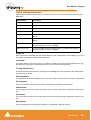
Hard Disk Space Requirements
A complete software installation will require around 50MB of disk space for the Pyramix software itself
and approximately 10MB of disk space for the Virtual Transport.
In addition, you will need hard disk storage for any captured audio media files. As a rule of thumb, one
Gigabyte of disk storage equals:
•
185 track minutes at 44.1 kHz 16 bits
•
125 track minutes at 44.1 kHz 24 bits
•
170 track minutes at 48 kHz 16 bits
•
115 track minutes at 48 kHz 24 bits
•
55 track minutes at 96 kHz 24 bits
For continuous multi-track recording applications, divide total available mono track time by the number
of tracks you will be using.
User Manual
20
User Manual : Pyramix Virtual Studio Overview
Please note that these are very rough estimates, and should be used only as a general indication of
storage requirements.
Operating System
Windows XP, Windows 2000 or Windows NT Workstation (v4.0 SP6 or higher) installed (never attempt
to install Pyramix on NT Server). Windows XP is preferred.
Drivers
Regularly acquiring and installing the latest Drivers/Firmware/Bios or Operating System available for
equipment such as: Graphic Cards, CD/DVD writers, Network Adapters, Motherboards, (but exercise
especial caution), external drives, RAID controllers and other third party hardware add-ons, will ensure
that your system will always perform as efficiently as possible. Always accept any ‘rollback’ options, just
in case the driver updates have unforeseen consequences.
Drivers should have the Microsoft digital signature, where available. However, the latest drivers will
often not be signed. In these cases use the latest driver which is known to work or otherwise certified.
This may require a little on-line research.
Graphics cards and optical drives, in particular, benefit from the most recent stable driver updates.
Keeping Windows (and DirectX) up to date with latest service packs is also, in general, a positive move
towards maintaining a healthy system.
Note: These operations are not required for Mykerinos and Daughter cards simply
because the latest firmware for your hardware (if any) is automatically installed by the
most recent Pyramix installer.
Power Management
N.B. As with all Digital Audio Workstations and Non-Linear Editors, we recommend setting the PC to an
Always On Power management scheme. (Start > Settings > Control Panel double click Power
Options. Choose Always On from the Power Schemes drop down list.) This allows the monitor to be
turned off by the system but disables hard-disk turn off and Standby.
Note: The Mykerinos card is not designed to support Standby modes.
Other Applications
Like all Digital Audio Workstations, Pyramix works best when there are no other unnecessary applications or services running.
Video and Pyramix on one PC
To ensure a very smooth system (especially for seeking) playing video with Pyramix on the same computer, we recommend a Dual Processor PC, a dedicated hard drive for the video and Windows XP
User Manual
21
User Manual : Digital Audio Synchronization and TimeCode
Digital Audio Synchronization and TimeCode
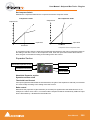
THERE MUST BE ONLY ONE SOURCE OF SYNC FOR AUDIO AND TIME-CODE
Digital audio relies on extremely accurate timing. In any digital audio system there can only be one
source of sync at one time. This is particularly important when planning multi-machine systems. If timecode is not locked to the same sync source as the digital audio then either the audio will work properly,
or the time-code. But NOT BOTH AT THE SAME TIME.
Ideally, in any system with more than one device, there will also be an independent source of sync. E.g.
a word-clock generator with multiple outputs. Each device is fed by a single output and configured to
use this source as its sync reference.
Example:
A location digital recorder records at a nominal 44.1kHz sampling rate generated by its internal crystal
oscillator and also records time-code derived from the same oscillator. Although the machine may be
running slightly slow or fast the digital audio and time-code will vary by exactly the same percentage.
When this location recording is played back on a machine locked to a stable sync source, digital audio
will play at the same rate as the workstation and the time-code will be correct.
Consider an alternative scenario:
A digital multi-track is used as a location recorder, synced to its internal oscillator. Time-code is
recorded on an audio track sourced from, say, a camcorder. When the resulting tape is played back on
a machine locked to a stable sync source, the audio will be at the correct rate but the time-code will
‘drift’ in relation to it. The amount of this error is known as ‘DELTA’. Delta is simply the result of the following formula: Internal TC minus External TC minus Offset = Delta. Where such a recording exists and
it is imperative the time-code on tape is the master reference there are several solutions. The preferred
options are:
Play back the tape with the machine chase-synchronized to the recorded time-code. Since the digital
audio is not locked to the time-code the sample rate will drift. If recorded directly, this would result in
missed or duplicated samples. I.e. unpleasant audible artefacts. Therefore, in order to record the audio
in Pyramix it must go via a digital audio synchronizer/sample rate converter synchronized to the master
word-clock source. This will then present Pyramix with digital audio at the correct rate.
Alternatively, the audio could be converted to analogue then fed into Pyramix via an analogue to digital
converter.
User Manual
22
User Manual : Installing Pyramix Virtual Studio Hardware
Installing Pyramix Virtual Studio Hardware
Mykerinos Board Installation
The Merging Technologies Mykerinos board can be installed in any free PCI slot in your PC. In general,
it is best NOT to install the board in the PCI slot adjacent to an AGP graphics adapter; and in a PCI slot
which may be physically shared with an ISA slot.
Please consult the merging.com website for current compatibility information.
Make absolutely certain the PC power is OFF before installing the board!
With most of the current generation motherboards this means either the mains switch on the power supply or the power outlet switch. Where no switch is provided, either on the PC or the supply socket, then
the PC should be unplugged.
Always observe proper static precautions when handling any PC boards! Use a static strap, and/or be
sure to firmly ground yourself to the computer power supply, chassis or if the PC is unplugged, to a
known good earth before handling and installing the Mykerinos board.
Some PCs have batteries, cables, jumpers, etc. which could prevent proper board seating in one or
more slots. Make certain the board is firmly and fully seated before switching on.
Multi-board installation
Multiple boards must be installed in adjacent slots. To enable multi-board operation, all Mykerinos cards
in the PC have to be connected together using a special HDTDM ribbon cable. This cable has to be
plugged into the multi-pin connectors located on the top edge of the I/O daughter cards. Please contact
your Merging Technologies dealer for information on how to order this HDTDM ribbon cable.
HDTDM
The HDTDM cable has the following functions in a multiple Mykerinos board installation:
a) synchronization (to 1/512th of an audio sample accuracy) This enables Pyramix to "see" a single system comprised of a large pool of DSP power and I/O resources spread over separate cards.
b) transfers all audio signals (Live Inputs, Internal Send/Return Busses, Mix busses, Aux busses, Live
Outputs, etc. between all the Mykerinos I/O daughter-cards which comprise the multi-board system.
Daughter-cards
Please see Appendix II I/O Daughter-card Options on page 339 for a description of the available
daughter-cards.
External Audio D/A-A/D Converter Boxes
Most of the I/O options for the Mykerinos board are digital. Pyramix will often be used with external
audio D/A (for playback) and A/D (for recording) converters. Many such converters are available from
Merging Technologies as options: for example, the Merging Technologies Dua II and Sphynx boxes.
Contact Merging Technologies Sales for more information.
Capabilities of third party D/A - A/D converter boxes are widely variable. Please check with the manufacturer to ascertain which sample rates, word lengths and number of I/O channels are supported. You
will need this information later to appropriately configure the Pyramix software.
User Manual
23
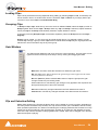
User Manual : Cabling Pyramix in your System Environment
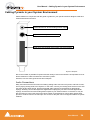
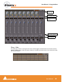
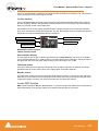
Cabling Pyramix in your System Environment
Please read this in conjunction with the guide or guides for your specific interface daughter-cards and
external interfaces/converters.
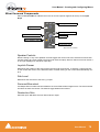
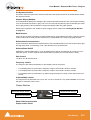
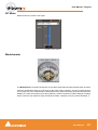
3.5mm Mini-Phone Jack for analog monitor output
8-pin Mini-DIN for sync breakout cable
Area where I/O Daughter Card output connectors appear
Mykerinos Backplate
Due to the number of possible I/O options and the variety of user environments it is impossible to cover
all the variations of cable connections to and from Pyramix.
However, here are some general rules and examples:
Audio Connections
Many users will have A/D Converters for feeding analog audio sources into Pyramix, and D/A Converters for playing analog audio out of Pyramix. In this case, connect your analog audio sources to the A/D
Converter analog audio inputs, and the A/D digital audio output(s) to the Mykerinos digital audio
input(s). Similarly, connect the Mykerinos digital audio output(s) to your D/A Converter digital audio
input(s), and the D/A Converter analog audio outputs to your studio monitors or recorders. It may be
also be useful to connect the stereo mini-phone output on the Mykerinos card to either stereo headphones or a stereo monitor console input. The source for this jack can be configured inside the Pyramix
software.
User Manual
24
User Manual : Cabling Pyramix in your System Environment
Sync, Video and Time Code Connections
In any digital audio system, it is VERY IMPORTANT all interconnected units are locked to the same
sync reference. A digital audio signal itself can sometimes be used as the master sync source, but a
high stability video or wordclock signal is usually preferable.
The Mykerinos board can be configured inside the Pyramix software to act as either a sync master, or to
slave to a variety of incoming signals.
Decide which device in your system will provide the master sync reference, then ensure that all other
digital audio devices in your system take their synchronization from it. This will require routing appropriate cables --whether digital audio, video or wordclock cables-- to the various other devices and may
also involve a separate sync reference generator and or distribution amplifiers.
If Pyramix is configured as the master (Internal sync), other digital audio devices will probably be able to
lock to the digital audio output from Pyramix. However, Pyramix can also be configured to output a
wordclock signal at the Video output BNC connector (Pyramix Synchronization option required).
If Pyramix is configured as a slave to an external device, Various synchronization signals can be
accepted.
•
To lock to incoming digital audio, connect an appropriate digital audio signal to a Pyramix digital
audio input.
•
To lock to incoming video, connect an appropriate video signal to the Pyramix Video Reference
input (Pyramix Synchronization option required).
•
To lock to incoming wordclock, connect an appropriate master wordclock signal to the Pyramix
Video 2 Input (Pyramix Synchronization option required).
•
To set the termination jumpers provided on the Mykerinos board, please see the Mykerinos User
Guide.
Pyramix can either output or lock to incoming SMPTE / EBU time code.
•
If a master LTC time code output from Pyramix is needed, cable the Pyramix LTC time code out
RCA jack or XLR to any other devices slaving to this output (Pyramix Synchronization option
required). Pyramix always generates time code when playing.
•
To lock Pyramix to an incoming LTC time code signal, cable the LTC time code output from the time
code source to the Pyramix LTC input RCA jack or XLR (Pyramix Synchronization option required).
Pyramix can accept and generate VITC in standard PAL/NTSC formats. It can also provide BITC (Burnt
In Time-Code) on its video outputs.
MIDI Connections
To use Pyramix MIDI functionality with external equipment, you will require a MIDI interface. Many current motherboards include an on-board MIDI interface. If yours does not, it is a simple matter to add
one. This can be either an internal PCI card or an external unit connected via a USB port or an RS232
serial COM port.
User Manual
25
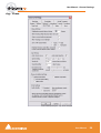
User Manual : Installing Pyramix Virtual Studio Software
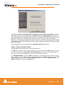
Installing Pyramix Virtual Studio Software
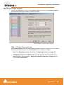
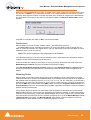
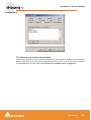
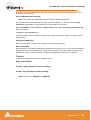
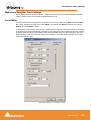
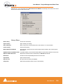
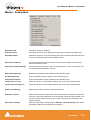
Driver Signing
Important! Before attempting to install the Pyramix Virtual Studio software please check the
following setting:
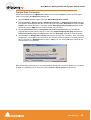
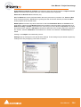
Start > Settings > Control Panel > System : Hardware
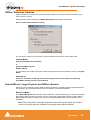
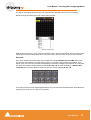
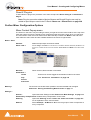
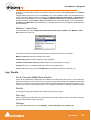
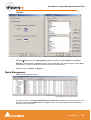
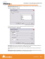
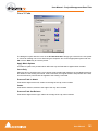
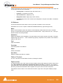
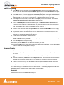
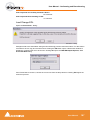
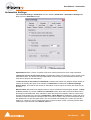
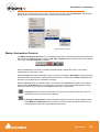
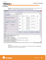
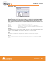
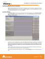
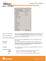
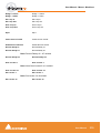
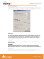
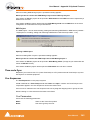
Click on the Hardware Tab, then click on Driver Signing. The Driver Signing Options dialog opens:
Driver Signing Options dialog
Make sure the middle option Warn is selected.
Running the Installer
Pyramix Virtual Studio and Virtual Transport software is provided on a CD-ROM. You may also
receive software updates as a download from our ftp site. In either case, install the Pyramix and Virtual
Transport software by running the Virtual Transport and Pyramix Virtual Studio Installer programs.
Choose the default location to install the software unless you have good reason to do otherwise. You
will also be asked to a create folders for your media files and for CD Images (these can be changed
later). If you receive any error messages regarding the Microsoft Digital Signature, ignore these and
continue on with the installation by clicking ‘Yes’.
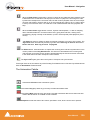
Important! After installation, please reboot the PC before attempting to launch Pyramix Virtual
Studio. Then open the VS3 control panel application (Start > Programs > Pyramix > VS3
control panel). The default Tab page is Configuration. Select 8 in the Internal Return Busses drop down menu box then click on the Autorouting button followed by the OK button.
When the VS3 panel, Do you want to save routing? dialogue box appears, click on OK to
close the VS3 control panel.
Double-click on the Pyramix Virtual Studio desktop icon to launch Pyramix.
User Manual
26
User Manual : Installing Pyramix Virtual Studio Software
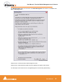
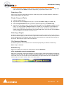
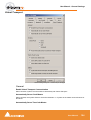
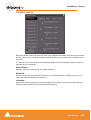
Enabling Pyramix Virtual Studio with your Software Key
Pyramix Virtual Studio is protected by a special software Key. Once you have registered your software
you will be provided with this Key or Keys (depending on the chosen options).
Entering your Key(s)
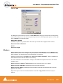
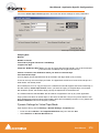
After the Pyramix installation process you will be prompted to enter your Authorization Key. If you click
Yes the MT Security Settings dialog will be launched automatically, allowing the Key or Keys to be
entered immediately. If you choose not to enter your Key at this point you can do so later by choosing
one of the following procedures:
1. Double-click the file YourPersonalKeyXXXXX.mtk. This is attached to the email containing your
Key(s).
2. Open the MT Security Settings Control Panel
(Windows Task Bar Start > Control Panel > MT Security Settings),
click the Import Key button and browse for your Key file called
YourPersonalKeyXXXXX.mtk
3. Open the MT Security Settings Control Panel (as above), in the Registration section select the
board number corresponding to the serial number for your Keys or HASP Key for a dongle, click the
Enter Key button and type your User Name, Company Name and Key then click OK. Repeat this
step for each Keys listed in the email.
Changing or re-entering a Key
Should you need to subsequently change or re-enter a Key, follow the appropriate option above.
The key system is "smart". Only one key or set of keys is required regardless of the number of boards in
a system. Any card can hold this key set as the authorization is processed based on a "Logical OR" of
all keys present on any and all Mykerinos boards. Of course this Logical OR will only process keys with
identical User Name and Company Name to the one entered in the key enabling dialog box.
User Manual
27
User Manual : Pyramix User Interface
Pyramix User Interface
The Pyramix user interface has evolved into an extremely powerful tool for manipulating audio. Commands and functions can be accessed from pull-down menus, pop-up menus, Tab windows and keyboard shortcuts.
There are generally several ways of accessing any given function in Pyramix. This helps users to work
in the way they find most comfortable for the type of projects they are undertaking. It also means ‘Power
Users’ can develop highly efficient operating procedures.
It is perfectly possible to casually use Pyramix without discovering all of the many possibilities on offer.
However, by looking deeper, a far more rewarding experience awaits.
Mouse Modifier Keys
The range of possible actions resulting from a mouse click are massively extended by the use of Keyboard Modifiers. These greatly aid productivity and are well worth learning. Please see: Appendix I
Mouse Modifier Keys on page 336
Context Menus
Right clicking over objects on screen such as clips, mixer strips and controls and track headers pops up
menus with commands and options relevant to the object.
Keyboard Shortcuts
In particular we would encourage users to use keyboard shortcuts and preferably the standard Pyramix
layout. Keyboard shortcuts can be fully customized and users of other workstations will discover we
have also provided familiar keyboard layouts to help them on their learning curve.
Macros
The Macro is another powerful feature of Pyramix. Macros are sequences of commands which can be
invoked by a single key or combination. Some macros are conditional. I.e their precise action depends
on variables in the project. A considerable library of pre-programmed macros is provided together with
an editor which enables users to construct their own macros.
Tutorial Project
An introductory tutorial project is provided on the Pyramix software CD-ROM. If you are new to Pyramix,
please work through the tutorial in conjunction with this manual. Together, they are a comparatively
painless introduction to many of the concepts and terms used in Pyramix.
User Manual
28
User Manual : Project Templates
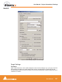
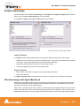
Project Templates
Pyramix provides the user with a number of Templates for various applications. A Template is a complete Pyramix Project, without any associated audio, specially configured to suit a particular type of
activity. Apart from configuring the appearance of Pyramix, the track layout and mixer design, templates
also include important optimizations to suit the activity.
Please see: Optimizing Pyramix on page 326
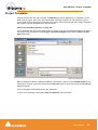
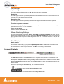
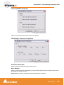
These templates also offer a good starting point for creating your own customized templates. To begin a
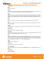
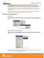
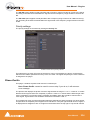
new project using a template choose Project > New from Template which opens the Select a Template file browser.
Select a Template dialog
When a template is opened a dialog box appears requesting the user to choose a Media Folder for the
new project. Unless the project is saved using the Save As option, the first time it is saved the Save As
dialog will appear.
Further Templates will be added as they are developed.
To save a new Template choose File > Save as Template, name and save.
User Manual
29
User Manual : Pyramix Concepts
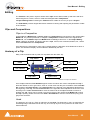
Pyramix Concepts
Project
A Project is the top level of organization. Projects are saved with the file extension .PMT. A Project
controls and keeps track of all the various elements you are assembling at a given time. A Project
always contains a Mixer and a Composition, viewed on the Timeline, or as an Edit Decision List
(EDL), plus Libraries containing Master Clips, Compositions, Mixer settings, and Fade settings.
Mixer
The Mixer, is the nexus of the Virtual Studio. The Mixer routes all audio into and out of a Pyramix
Project. It also determines audio sample rates and synchronization. The user configures the Mixer as
appropriate, for the number and type of inputs strips and output busses needed for a Project. Without a
properly configured Mixer, no audio can be recorded, mixed, or monitored.
Compositions
A Composition is any number of clips complete with edits and fades, level settings etc. placed on a
track or tracks in a time relation to each other and to the Timeline.
Timeline
The Timeline shows a graphic representation of the current Composition. and its location in relation to
the Playhead Cursor, In and Out Marker Cursors and various other Markers. All editing is done in the
Timeline, EDL or Fade Editor windows.
EDL
The EDL (Edit Decision List), is a textual and numeric representation of the same information shown
in the Timeline and Fade Editor. Changes made here are reflected in the Timeline and vice-versa.
Media Files
These are actual audio data files which can only be seen at the Windows level, e.g. in Windows
Explorer. In Pyramix, they are represented by Master Clips which reference the raw data files.
Master Clips
The concept of Master Clips is one of the keys to the power of Pyramix. An individual Master Clip is a
set of pointers that reference one or more Media Files.
Note that a single Master Clip references all Media Files in a multi-channel audio recording. E.g. a stereo recording can have one or two Media Files, (depending on whether there is a check in the One file
per track box in the Media Option section of the record page of the Project Information and Settings
dialog box.) (Project > Project Information and Settings - Record Tab).
When One file per track is checked, one invisible Media File is generated for each channel of a
recording but only one Master Clip. So.a stereo Master Clip references two invisible Media Files and
a Multi-channel Master Clip references as many invisible Media Files as there are channels in the
recording. check box ‘One file per track’), but will only generate one Master Clip.
A Master Clip can be mono, stereo, four channels, six channels, 24 channels, in fact there is no limit to
the number of channels that can be contained within a Master Clip. When a Master Clip is placed into
a Composition there is the option to place it where it was originally recorded.
User Manual
30
User Manual : Pyramix Concepts
Master Clips also contain attributes which identify parameters such as a File name, time code stamp
and other information.
Clips
The individual clips shown on the Timeline contain pointers to Master Clips which in turn point to
audio Media Files.
Media Management - Housekeeping
The Windows hierarchical filing system can easily become confusing and cluttered. Complex audio
projects generate thousands of more or less enigmatically named files. Keeping track of all the files
used in a project can become a nightmare even if the user is meticulous.
Pyramix uses the concepts of Media Drives/Folders and libraries to reduce the clutter and provides
management tools specifically designed for audio. This Media Management helps users to work in a
structured and simple manner whilst keeping track of all the project components.
Media Drives and Folders
Media Drives or Media Folders are Windows folders which contain Media Files. Pyramix needs to
specifically mount these Media Drives in order to access the Media Files contained therein. Once
mounted, suitable files are shown as Master Clips.
Provided the sampling rate is the same as the current project, these can be dragged and dropped or
copied and pasted directly into the Timeline or into a User library from the Media Management Window.
Libraries
Pyramix uses libraries to help make project organization tidier. Libraries are used to organize project
material into logical groupings. However, Libraries are not the same as Windows directories or folders:
they are only meaningful within the Pyramix environment. A Library is a database, containing a collection of pointers to different kinds of media objects.
User Libraries
User Libraries can contain Master Clips, Compositions, Mixer Snapshots, Plug-in Snapshots,
Fades Settings, etc…. Each Project can have an unlimited number of User Libraries open, each with
an unlimited number and mixture of contents.
N.B. In Pyramix User Libraries, there is no practical distinction between a section of a Composition
(Region) and a complete Composition. Either can be added to a User Library or to an existing Composition. This is an extremely powerful feature. A single clip copied to a User Library from the Timeline appears there as a Composition.
Automation in libraries
If the menu item Edit > Enable Automation Cut/Copy/Paste is enabled then any operation on clips
(Cut/Copy/Paste, Auto-Ripple, etc…) brings all automation data with it
If you drag a clip(s) to a library, all automation over that clip(s) is copied/pasted as well.
Global Libraries
Project Libraries are kept with the Project, Global Libraries are available to all projects and users of
the system. This can be helpful for sound effects or where several users need access to the same
source material to produce different end products.
User Manual
31
User Manual : Pyramix Concepts
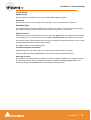
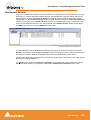
Offline / Reference Libraries
Offline or Reference Libraries are standard Pyramix Libraries and may be searched or filtered in the
same manner as others.
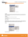
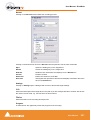
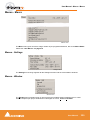
Offline libraries can be created in the Media Management Tab Window by selecting
Drive > Create Offline/Reference Library.
Create Offline/Reference Library dialog
The new library references all currently mounted media according to the choice made under
Original Media
Only selected Media Drives/Folders
or
All mounted Media folders
Offline Library
The new library can contain references to either all media present in the location(s) chosen in Original
Media:
Add all Media
Or there is the option of filtering out media already present in other libraries by selecting:
Filter Media already present in other libraries
Sound Effects / Large Projects and Offline Libraries
When used in the following manner Offline Libraries provide an extremely powerful organizational tool
for managing very large project libraries and, for example, sound effects libraries.
Mount The Media
In the Media Management Tab Window, Mount all folders or disks containing your audio files (as ripped
with LibraryLoader, mTools or any other source). We strongly suggest these files be in either PMF or
BWF (Broadcast Wave Format) as they both have a long description field, a unique identifier and a
timestamp.
Note: There may well be Copyright implications when working with ripped files. Please
ensure you comply with any restrictions on copying other people’s material.
User Manual
32
User Manual : Pyramix Concepts
Create An Initial Library
Select the Media Management Tab Window Menu item Drive > Create Offline/Reference Library
and choose All mounted Media folders and Add all Media. This will create an initial library referencing all your audio files. All the media files / disks may then be unmounted.
The library can now be re-organized, folders created, items duplicated etc. etc.
You can make searches (queries) or apply filters to your Offline / Reference library(ies) and, if Project >
Auto-mount Media is checked, each time an item is dragged onto the Timeline the appropriate audio
file will automatically mount. Or this can be done this manually by calling Project > Mount Referenced
Media.
Updating Libraries - Orphaned Entries
If the original audio files are moved or reorganized, just mount all the folders once again, load all your
libraries and call the Library menu command Update Referenced Media Paths.
Updating Libraries - Adding new files
If new audio files are added to your media disk(s), simply mount these folders, load all your libraries and
proceed as in “Create An Initial Library” above, but select the option, Filter Media already present
in other libraries. This will create a new library containing only references to the freshly added audio
files. These new items can then be copied/moved to any (or many) already existing Offline library(ies).
Project Libraries
When a new Project is created two Project Libraries are also created.
Composition Library
Each Project has a unique, read-only Composition Library. This contains short-cuts to every Master
Clip placed on the Timeline (present in the EDL) in the current Project. Note that the Composition
Library may be empty, I.e. nothing is placed on the Timeline but the user library(s) may contain Master
Clips and Compositions which all form part of the Project.
Default Library
Each new Project also creates an empty User Library named ‘Default Library’. This is provided to aid
housekeeping and is kept with the project.
Library Maintenance
If media is moved or the path to it is changed (E.g. by copy, backup or moving folders etc.) Libraries referencing the ‘orphaned’ media can have their paths updated by simply mounting all the media folders
involved and selecting Drive > Update Media Paths in the Global Libraries tab window
Track and Mixer Muting
There is a subtle difference between muting a Track Output (with the
button in the Track Header)
and muting the same signal in it’s associated mixer input strip. Muting a track stops disk access for the
track (There is a delay before the sound stops while the replay buffer is emptied). Muting a mixer strip
doesn't affect disk access but simply mutes the strip (Therefore muting is immediate). Muting track outputs enables multi-track recordings with many tracks (E.g. 48 track music recordings) to be edited on
hardware which cannot support this number of tracks. (E.g. a laptop) Providing the Clips are grouped
across all tracks, then any editing changes made on the tracks used for the editing guide will also be
reflected in the muted tracks. Track Grouping can be used to make operation simpler and more convenient.
User Manual
33
User Manual : Pyramix Concepts
Please see also: Grouping Clips on page 54, Track Groups on page 152
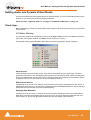
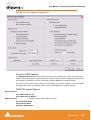
TimeCode Entry
TimeCode values in Pyramix can be changed by using Increment Decrement buttons, by using the on
screen numeric keys or by direct entry from the numeric keypad. an OK button or the ENTER key finalizes the entry. In Pyramix numbers are entered in time code fields from right to left, a block at a time,
progressively overwriting existing numbers.
This makes the most common TimeCode changes easy, I.e frames or seconds, without having to reenter the minutes or hours.
Clicking in a register inserts a red I-beam cursor and outlines the register in green. Entries must be
made in Hours : Minutes : Seconds : Frames order. So, to enter 10 Hours and 9 seconds and 15
frames, key: 1 0 0 0 0 9 1 5. BUT if you only want to change the seconds then you only have to enter the
seconds and frames E.g. to enter 9 seconds and 15 frames, key: 9 1 5 followed by ENTER. However, to
change 10:27:10:15 frames to 10:27:09:15 you would need to key, 0 9 1 5 followed by ENTER. In practice most operators always enter the leading zero even when it is not required, to avoid errors.
TimeCode Register
Arithmetic TimeCode Entry
An existing TimeCode value can have time added to or subtracted from it. I.e. a relative entry. Type the
number to be added or subtracted then, instead of pressing the Numeric Key Pad Enter, press - (Minus)
or + (Plus) on the main keyboard or CONTROL + Minus or CONTROL + Plus on the Numeric Key Pad.
User Manual
34
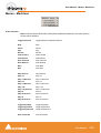
User Manual : Pyramix Concepts
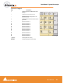
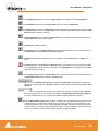
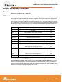
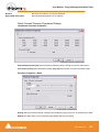
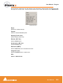
Numeric Keypad
Key
Command
/
Nothing (when in Placement Tool:
Done)
*
Capture current TimeCode
-
Delete last typed digit (same as
BACKSPACE)
+
Undo typed TimeCode and restore
previous
1
Enters Number 1
2
Enters Number 2
3
Enters Number 3
4
Enters Number 4
5
Enters Number 5
6
Enters Number 6
7
Enters Number 7
8
Enters Number 8
9
Enters Number 9
0
Enters Number 0
. (point)
Clear (Set all to zero)
ENTER
OK (Accept typed TimeCode)
Numeric keypad
User Manual
35
User Manual : Starting Pyramix Virtual Studio
Starting Pyramix Virtual Studio
By default the Installer will put Pyramix Virtual Studio into your Programs folder. It also places a Pyramix shortcut icon on the Windows desktop.
To start Pyramix Virtual Studio, double-click on the Pyramix shortcut icon on your Windows desktop.
Alternately, choose Start > Programs > Pyramix > Pyramix Virtual Studio.
The first time Pyramix Virtual Studio is launched, you will need to enter in your special Key to properly
enable the program (Please see: Enabling Pyramix Virtual Studio with your Software Key on
page 27). Upon program launch, you will see the main Pyramix Virtual Studio by Merging Technologies window with its Toolbar at the top, and transport controls and status displays at the bottom.
User Manual
36
User Manual : Beginning a New Project
Beginning a New Project
The Project is the top level of organization in Pyramix Virtual Studio. You need to start a new (or open
an existing) Project to capture audio, import files, edit, mix or add effects.
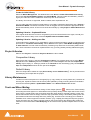
Templates
Pyramix has Templates for common tasks and you can save your own. To use an existing Template to
start a new Project choose Project > New from Template from the pull-down menus along the Toolbar at the top of the Pyramix Virtual Studio by Merging Technologies window.
Select a Template dialog
If you have started a project from scratch (see next section) and would like to save it as a Template
choose File > Save as Template. The file dialogue will open allowing you to save the template with an
appropriate name.
User Manual
37
User Manual : Beginning a New Project
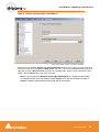
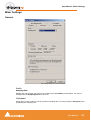
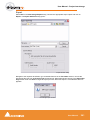
New Project from scratch
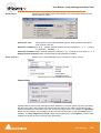
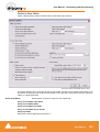
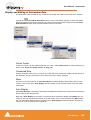
To start a new Project from scratch, choose Project > New. This launches the New Project Wizard,
which will lead you through the steps to create a new project.
New Project Wizard - Choose a Project Type dialog
Step 1: Choose the project type
Choose Editing Project, select the required sampling rate and resolution (number of bits) or accept the
defaults (44.1kHz, 16 bits), then click the Next button which will lead you to step 2.
Note: The Digitizing Session is described in: Digitizing Sessions on page 177,
DXD Mixing Projects and DSD Projects, the other possible choices available in the
New dialog box, are described in: Appendix III Optional Features on page 341 and
in the separate DSD Guide.
User Manual
38
User Manual : Beginning a New Project
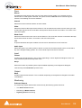
Step 2: Setup a new project workspace
New Project Wizard - Setup a new Project Workspace
Checking the box labeled: Setup a new Project Workspace, allows you to name the new project and
choose a location for the Project and Media Files. Type in a name for the Project and either type in a
valid path or use the Browse button to browse to a suitable folder. When you have entered the information, click the Next button to get to the next step.
Note: If you uncheck the Setup a new Project Workspace box, when the new project
is created it will be given the working name Project 1 (or the next available number if
Project 1 already exists) and the save path will be the default.
User Manual
39
User Manual : Beginning a New Project
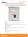
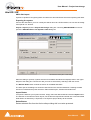
Step 3: Choose a Mixer
New Project Wizard - Select a Mixer Preset dialog
A new Project needs a properly configured Mixer. The Mixer, also called the Virtual Studio, is used to
route all signals into and out of Pyramix; it also determines the sample rate and synchronization source
for the Project.
Use Default Mixer
Loads the currently designated Default Mixer preset. N.B. The sampling rate of this preset takes precedence over the sample rate set in the Editing Project selected in the Choose Project Type dialogue. If
no Default Mixer has been defined and Finish is clicked the Blank Mixer window opens. Please
see: Blank Mixer Dialog on page 43
Use a Preset
Choose one of the large number of supplied Mixer Presets (and User Presets if any have been created)
by clicking on its description. (The Use a Preset Radio button is automatically selected) Double-clicking
a Preset selects the preset and invokes the Finish function. I.e. opens the new Project with the selected
mixer.
User Manual
40
User Manual : Beginning a New Project
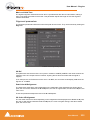
Mixer Wizard
If none of the existing presets is considered suitable, or you just want to start from scratch then
selecting Use Mixer Wizard and clicking the Next button opens this dialog box:
Configuration Wizard busses dialog
Select the type(s) of busses required using the check boxes and the number needed from the
drop down lists on the right. Click the Next button to move on to the next page.
Configuration Wizard strips dialog
Select the type(s) of channel strips required using the check boxes and the number needed
from the drop down lists on the right. Click the Next button to move on to the next page.
User Manual
41
User Manual : Beginning a New Project
.
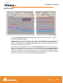
Configuration Wizard auto connect dialog
Checking the Connect automatically as many inputs and outputs as possible check-box
will create the same number and types of Tracks as there are Input Strips and connect as
many as possible to the available physical inputs in ascending order and output Busses to the
physical I/O attached to the Mykerinos board(s) and Track outputs to Mixer Input Strips,
although you can easily reconfigure this later. If the box is not ticked, the tracks will be created
in the same way with Track outputs connected to Mixer strips but no physical Inputs or Outputs
will be connected.
Clicking Cancel opens the new Project with a Blank Mixer Window (See below).
Step 4: Open the New Project
Clicking Finish creates the Mixer and opens the new Project.
The Mixer you configured above will now appear on the screen in a separate Mixer window. It will contain the number and kind of Input Strips and Output Busses defined. It can be moved anywhere on
the screen by clicking and dragging on its top bar, or be minimized or hidden.
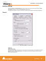
It is VERY IMPORTANT to ensure the Mixer’s sample rate, synchronization and I/O mode are configured correctly. To check or adjust settings, right-click anywhere on the Mixer window, then choose Settings > General... which will open the Mixer Settings dialog box. (Or choose Settings > Mixer
Settings : General from the main Settings menu.
User Manual
42
User Manual : Beginning a New Project
Blank Mixer Dialog
Note: If you click the Finish button before defining a Mixer, the Default Mixer will be
used and the new Project opened. If no Default Mixer has yet been defined this dialog
opens:
Blank mixer dialog
Use right mouse button to configure your mixer
This is the equivalent of right-clicking on a blank area of an existing mixer. We recommend only experienced users choose this option. Please see: Creating and Configuring Mixers on page 69
Creating a mixer in this way can be very time consuming. It is much faster to either:
Click here to use the Wizard
Please see: Mixer Wizard on page 41
Or, simply:
Double-click on a Mixer preset
Pick one from the list which most closely matches your requirements, then configure it to suit when the
new Project has opened.
User Manual
43
User Manual : Getting Audio into Pyramix Virtual Studio
Getting Audio into Pyramix Virtual Studio
There are two basic methods of getting audio into Pyramix initially: you can record audio directly into the
program, or you can import previously existing audio files.
Please see also: Digitizing Sessions on page 177 and External Machines on page 174
Check Sync
Before attempting to record any audio please check Pyramix and the audio source(s) are synchronized
as you intend.
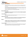
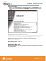
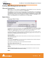
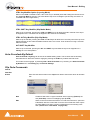
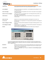
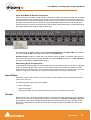
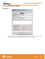
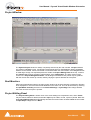
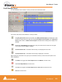
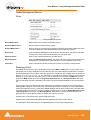
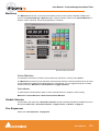
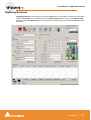
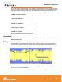
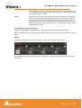
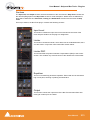
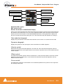
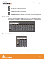
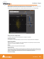
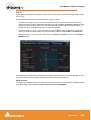
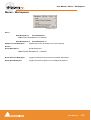
I/O Status Window
The I/O status window can be opened by clicking in the Sync: xxxxx section of the Status bar (bottom
right of the main Pyramix window. (the XXX’s are the current sync source)
This window shows useful information about the input and synchronization status of Pyramix.
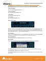
I/O Status window
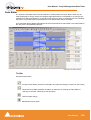
Input sources
All the possible input sources are shown, each with an associated red and a green light. The green
lights show the presence of a valid digital signal (This does not necessarily mean, that the sampling rate
of this input matches the current clock source of Pyramix). When the red light is on and steady, Pyramix
is using this input as it’s clock reference and is successfully locked up.
Default Clock Source
If Pyramix is set up to lock to an external clock source but cannot get a valid signal from this source, it
will switch to Internal clock. In this case the red light associated with Internal will be on, and the red light
associated with the intended clock source will be blinking.
Sampling Rate Mismatch
If Pyramix is set up to lock to an external clock source and the sampling rate set in the Virtual StudioMixer does not match the sampling rate of the clock source, the green light associated with the clock
source will be on, but the red light will be blinking showing the sampling rate mismatch.
User Manual
44
User Manual : Getting Audio into Pyramix Virtual Studio
Pyramix audio file format
Unless there is a good reason for using another file format for recordings we strongly recommend using
the default .PMF file format. This will give the best performance in a number of key areas. For further
information please see: Optimizing Pyramix on page 326
Recording Audio into a Pyramix Virtual Studio Project
Start a new Project, or open an existing one. Make certain the Mixer sample rate and sync source is set
as desired. You will need to configure at least the same number of Mixer channels as Tracks you wish
to record.
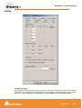
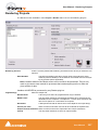
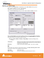
Before beginning audio capture, check or select appropriate record settings. Open Settings > Information & Settings : Record (alternatively use the keyboard short-cut Ctrl - f and click the Record Tab)
There are many settings in this dialog page, but for now you need only be concerned with; Destination
Drive (Media File folder), Resolution (bit depth or word length) and Format (file type). As previously
mentioned, unless you have a specific reason for using a different format we recommend using the
default PMF format.
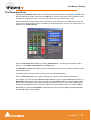
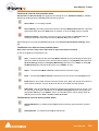
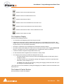
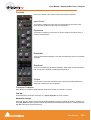
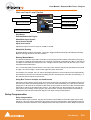
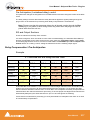
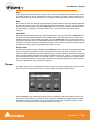
Track Record Modes
Each Track has a tri-state Record Ready toggle button, located to the left of the Track itself in the
Track Information and Setup Area.
Tip: Right clicking on a track arming button opens the Settings > Information & Settings dialog
immediately on the Record Page.
Play
The Green Dot in the Track Header indicates Record Safe mode, the default when Tracks are newly
created. When in this state, the Track cannot be recorded to.
Record Ready (Manual)
Click on the Green Dot once to toggle to Record Ready mode. This is indicated by the dot turning into
the Red Dot. The Track will now go into Record mode immediately when the Master Record button is
pressed in the Transport Strip or Transport window.
Record Punch In (Auto)
Click on the Red Dot to toggle to Record Punch In mode. This is indicated by a Red Dot flanked by 2
red vertical lines. In this mode, when the Master Record button is pressed in the Transport Strip or
Transport window, the Track will stay in Play mode until the current Mark In point is reached, then the
Track will go into Record mode. It will stay in Record mode until the current Mark Out point is reached.
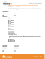
After Recording
New recordings will be processed according to the settings made in the Settings > Information and
Settings : Record page. Please see: Record on page 107
User Manual
45
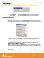
User Manual : Getting Audio into Pyramix Virtual Studio
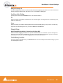
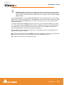
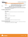
If the Prompt for name after recording box is checked the Record Name dialog appears when the
recording is finished and the transport stopped.
Record Name dialog
Type a name for the recording (or leave the default) then select one of the button options.
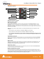
AutoPunch Mode
AutoPunch when Chasing TimeCode
If tracks are set to Auto-Punch mode (Alt+Click on Rec Ready button) then the system will start recording (after locking to TC) when it reaches the Mark In point and punch out when it reaches the Mark Out
point.
If the Mark In is located before the current location (and the Mark Out far after) then the system will
immediately record once locked and stop recording when unlocking.
Recording from a tape with Discontinuous TimeCode
Pyramix AutoPunch Mode makes this a simple operation.
Place the Mark In at 00:00:00:00 and Mark Out at 23:59:59:24 (default values for a new project)
Connect LTC Out from the tape machine into Pyramix
Set Chase mode to HARD CHASE
Rewind the tape
Press Play on the tape machine
Each time a valid TC is encountered Pyramix will lock and start recording a new clip, then stop when the
timecode stops or jumps. A separate media will be created for each continuous section of timecode on
the tape.
User Manual
46
User Manual : Getting Audio into Pyramix Virtual Studio
Importing Audio Files into Pyramix Virtual Studio
Importing Audio Files
Different file types with different bit depths (word lengths) can be freely combined in a Composition.
Simply Mount the Media Drive or Media Folder and drag-and-drop the required material into the Timeline.
Files with different sample rates can also be freely combined.
Note: If a clip has a different sample rate to the current project the clip will play at the
‘wrong’ speed! E.g. in a 48kHz project a 96kHz clip will play at half speed. With most
material this will be glaringly obvious, however with sound effects, smaller differences
in rate (E.g. 44.1kHz - 48kHz) may well go unnoticed.
Mounting Media Drives
If many audio files already exist in a single Windows directory or folder, it is easy to mount that Windows
folder as a Pyramix Media Drive. Once mounted, the supported files become available for use in a
Project.
1. Start a New Project or Open an existing one.
2. Click the Media Management Tab in the Project Management Panel to open the Media window, or
double click to open it as a floating window.
3. Select Drive > Mount Media Drive. This opens the Choose a media folder to mount dialog box.
4. Click the Browse... button, then navigate to the Windows directory containing the audio files you
wish to import.
5. Click the OK button to mount that Windows directory as a Media Drive. All supported audio file
types will be seen by Pyramix, and be available for use in the Project. A check in the Recursive box
means Pyramix will look in sub-directories of the chosen folder as well as the root. A check in the
Permanent mount box means Pyramix will attempt to mount the folder whenever the application is
launched. I.e. make it available to all Projects.
User Manual
47
User Manual : Getting Audio into Pyramix Virtual Studio
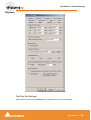
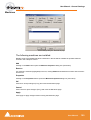
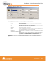
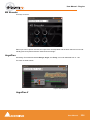
Sample Rate Conversion
Where the sampling rate of a Media File is different to the current Project, Pyramix offers a simple
means of converting the Media File’s sample rate.
1. Select a Master Clip file or files in the main Media Management window.
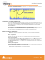
2. Choose Convert > Quick Convert > Samplerate Converter. A Samplerate Converter dialogue
box appears. Radio buttons offer the choice of two text entry fields, New name for the file or Add
Suffix to the existing filename. A checkbox selects Keep Original File Format otherwise the file
will be converted to PMF format as well as sample rate converted.
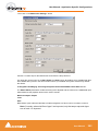
3. Selecting Properties opens the Samplerate Converter Properties dialog box. Choose the
required target sample rate by clicking on one of the Output Sampling Rate [Hz] radio buttons.
Conversion Quality defaults to High with the option of Very High. Click OK to close the dialog
4. Choose OK in the Samplerate Converter dialogue box to begin the conversion. When converting
multiple files, choose OK to convert the files one at a time with the possibility of changing parameters on each file or, if Add Suffix was chosen in step 2, you can choose OK all to convert all the
selected files in one operation.
Convert Media Files dialog
Note that bit depth (word length) is not changed with a sample rate conversion. Options for converting
bit depth or normalizing can be accessed via the Convert > Quick Convert > sub-menus.
User Manual
48
User Manual : Practical Media Management and Libraries
Practical Media Management and Libraries
Clips and Compositions
Master Clips can simply be dragged from Media Drives to User Libraries for purposes of clip organization, grouping, etc. just as they are dragged into Compositions
User Libraries are not restricted to storing individual clips. Whole Compositions or selected Regions
of Compositions, including all the clips in a Composition in relation to each other on multiple Tracks
may be placed in a library. To do this, select one or more clips in a Composition, hold down the ShiftAlt keys and drag the selection from the Timeline to the Library, or hold down the Shift-Alt keys and
drag the whole Composition from the Overview panel to the User Library.
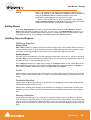
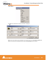
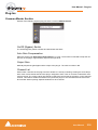
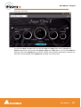
Media Folders
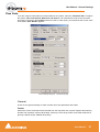
Managing Media Folders
Choose a media folder to mount dialog
This dialog can be opened in several ways. From the Media Management Tab Window Drive > Mount
Media Drive or by right-clicking a Media Drive or Media Folder entry in the right-hand pane, and from
the New entry in Media Folder drop-down list menus in various Pyramix Windows.
The text box allows a complete path to be entered or a Media Folder or Drive can be chosen from the
drop down list. Alternatively, a new Media Folder can be created by typing its name in the text box. The
new folder will be created below the current one in the tree.
Permanent Mount
When checked, the chosen folder will be mounted at start up for all future Projects. (Can be useful for
sound effects libraries etc.)
Quick Mount
If you check this Quick Mount box the system will load the 'QuickMount' library instead of parsing all
the media files in the folder. (See below) Recursive
When checked, all sub-folders of the chosen folder will also be mounted.
Reset Recent Mounted Folders List
Clears the drop-down list. The list contains all folders that have been mounted since the list was last
cleared.
Browse...
Opens the Browse for Folder dialog box which enables any Windows drive or folder on the local
machine or across a network to be selected for mounting.
Mount
User Manual
49
User Manual : Practical Media Management and Libraries
Mounts the selected Media Drive or Folder. To create a new Folder, simply type a name in the text entry
box and click on Mount. (If you want the new folder to be created somewhere other than the current
path tree, either type the full path or use the drop-down list or browser to navigate to the desired directory, then add the new name in the text entry box after the path) The Mount a media folder info box
appears:
Mount a media folder info box
Click Yes to create the new folder, or No to cancel the operation.
Quickmount
When a folder is mounted normally, a library called '__QuickMountLocal.pml' (or
'__QuickMountRemote.pml' depending on whether you access this folder locally or through the network) is created and stored in the original folder. This can dramatically reduce the time taken to mount
media files when a project is opened.
Note: The double underline is an integral part of the filename
If the QuickMount library is not found then a standard mount is performed and a QuickMount library is
created to enable future Quick Mounts to take place.
If new media files are added (or removed) to or from a previously 'Quick Mounted' folder, select the
Media Manager > Refresh menu item to update the Quick Mount library.
If the Use Quick Mount whenever possible check box in the General Settings > Locations page is
checked, permanently mounted folders are automatically 'Quick Mounted' when the application is
started
Mounting Rules
When a folder is mounted Pyramix always tries to group multiple mono files that are part of a single
multi-track media when viewed in the Media Manager so the multiple mono files appear as a single item
with multiple tracks numbered in the form A 1-2 or A 1-8, or A 1-2, 7-8, etc. Otherwise, you would see a
separate entry for each mono file whether or not it is part of a multi-track 'set'. In order to achieve this in
the case of BWF files Pyramix looks at the BWF header and uses the Originator Reference field as a
Unique Identifier with some rules as defined by the EBU organization and some conventions adopted
between various manufacturers.
It may happen that some files do not follow these rules and therefore sometimes the Pyramix Media
Manager fails to properly mount these files. Sometimes some files are missing, or some tracks within a
multi-track media are missing. The Pyramix Media Manager detects these conflicts at the time the folder
is mounted and informs the user of such a problem, prompting him to go to the Media Manager > Drive
> Mounting Rules menu item. The Mounting Rules dialog allows a variety of different rules to be
applied for this or these Media Folders so all files are properly mounted.
User Manual
50
User Manual : Practical Media Management and Libraries
The Mounting Rules dialog can be found in the Media Management Tab window in the Drive menu :
Drive > Mounting Rules
Mounting Rules dialog
Folders where a conflict has been detected appear in Red.
Folders where a special Mounting Rule has been applied now appear in Dark Green.
The description of the Rules that can be applied appears in the Mounting Rules dialog
User Manual
51
User Manual : Editing
Editing
The Timeline is the place in Pyramix where audio clips can be edited, faded up and down and otherwise arranged into a mono, stereo or multi-channel digital audio Composition.
A Project Editing Panel containing the Timeline will be visible as soon as you open a Project.
The Fade Editor provides elegant alternative methods of viewing and adjusting the parameters of edits
in the Timeline.
Clips and Compositions
Clips in a Composition
As with clips in a Media Drive or Library, clips in a Composition are just pointers to the original audio
Media File. Any actions performed on a clip in a Composition will affect neither the original audio
Media File, nor the Master Clip in the Media Drive or Library it came from. In the Project Editing
Panel, a clip can be edited, shortened, split into 2 clips, moved, level controlled, deleted, etc., and all
actions will ONLY affect the Composition.
Once placed in the Composition, each clip by default displays a Waveform of the Media file to which it
points. This Waveform display can be enabled or disabled by the user.
Anatomy of a Clip
Many Edit Commands refer to parts of a clip rather than the entire clip.
Clip Name
Waveform Display
Head
Tail
Trim Handle
Fade Handles
Clip Gain
Sync Point
Features of a Clip in the Timeline
Once a clip is selected, Trim Handles appear at each end which are used to manipulate the clip. If
these are difficult to see or get hold of, zoom in on both axes until they are accessible. Each Trim Handle consists of 3 Control Points. The Control Points on the left side of the clip allows adjustment of
the beginning of the clip, and the Control Points on the right side allows adjustment of the end. Click
and drag on the middle Control Point to move the head or tail of the clip as desired to shorten or
lengthen the clip. These can be moved out to the full extent of the original audio Media File to which
the clip is pointing. Select the menu item View > Show Media to view the unused audio (if any) as a
grayed out waveform.
Head
The beginning of a clip on a Track is referred to as the Head. The Head may or may not represent the
actual beginning of the Media File for the clip, since the clip is just a set of pointers to an area of the
whole media file.
User Manual
52
User Manual : Editing
Tail
The end of a clip on a Track is referred to as the Tail. The Tail may or may not represent the actual end
of the media file for the clip, since the clip is just a set of pointers to an area of the whole Media File.
Sync Point
The Sync Point is an internal reference point inside the clip. This defaults to the start of a clip until
moved.The Sync Point may be moved by dragging its handle within the clip. If the Play cursor is positioned over some part of the clip, the Sync Point may be snapped within the clip to the position of the
Play Cursor by choosing clips > Set Sync Point to Cursor.
Trim Handle
The Trim Handle is the middle handle available at either end of the clip when the clip is selected. This
handle is used to shorten or lengthen the clip (trim the clip in or out) up to the limit of the available
media. To trim the clip, drag the handle.
Fade Handles
The Fade Handles are the top and bottom handles available at either end of the clip when the clip is
selected. The handles are used to create a fade in at the beginning of the clip, or a fade out at the end
of the clip. To create or adjust a fade, drag one of the trim handles to create the desired fade in or fade
out. The top handle adjusts the fade within the clip and the bottom handle trims the clip in or out as you
adjust the fade. If the Top Handle is used with the CTRL key modifier, a symmetrical crossfade is created with any adjacent clips, centered at the original end point of the selected clip. If no adjacent clip
exists, then it extends or shrinks the duration of the fade while maintaining the duration of the selected
clip.
Waveform Display
Clips can appear either as a block with the clip name inside, or can show the audio waveform of the
media referenced by the clip.
Clip Name
The name of the clip is shown unless suppressed. View > Waveform > Hide Clip Name when Waveform Shown.
Clip Gain
The overall Gain applied to the clip is shown. This value is displayed in decibels.
Gain can be adjusted by selecting Clips > Clip Gain. The Gain window appears. If a Region is
selected the Gain will be changed on all clips in the selection.
User Manual
53
User Manual : Editing
Locking Clips
Clips can be protected from being displaced during editing by selecting Clips > Lock. A locked clip cannot be moved in time or to another track until it is unlocked. Clips > Unlock. If you simply wish to prevent loss of sync select Clips > Lock Horizontal Drag.
Grouping Clips
To Group multiple clips, whether they are on the same or different Tracks, select the clips you wish to
Group together. Now choose Clips > Group. When any clip in a Group is selected, copied, deleted or
moved, all clips in its Group will be similarly selected, copied, deleted or moved.
To ungroup previously Grouped clips to treat them separately, select the Group and choose Clips >
Ungroup.
Groups can be nested. I.e. one group may be inside another group. For example a stereo or multichannel clip is simply a group of mono clips. Stereo or Multi-channel clips may be ungrouped into individual mono ones in the same way as any other group.
Gain WIndow
The Gain window allows the gain to be set for the current selection. The gain value can be
typed into the box at the top of the strip or set by clicking and dragging the fader
Mute when checked, mutes the selection but retains the gain value
Sel. box (Selection). When checked, the gain change will be applied to the whole
selection (default is checked)
Rel. box (Relative) When checked and a series of clips are grouped, the gain
change is relative to pre-existing levels
When neither box is checked any gain change is only applied to the clip which was
last right clicked (even if others are selected)
OK button makes any changes selected in the Gain window and closes it
Cancel button cancels any changes selected in the Gain window and closes it
Gain Window
Clip and Selection Editing
Master Clips appear in the Timeline as blocks which can be edited on a track (or tracks, depending on
how many tracks the Master Clip contains) The clip can be trimmed, split, crossfaded, and have many
other operations performed on it without ever affecting the underlying media file. Each instance of a clip
references the entire media file, and can always be "opened up" by using the Trim Handles to reveal
more of the clip until the complete underlying Media File is visible. Clips can be dragged in the Timeline
while the transport is playing.
User Manual
54
User Manual : Editing
Clip Properties
Clips > Properties opens the Properties window for the selected clip. If multiple clips are selected,
opens the Properties window for the first clip selected:
Selection Window
Selections and Region Selections
Selection Operations
Many editing operations in Pyramix can only be carried out if a clip or region is selected.
There are two ways of selecting material in the Timeline. Whole Clips and Regions.
User Manual
55
User Manual : Editing
Clip Selection
Clicking in a clip selects it (the color becomes darker and Handles appear). The whole clip is ready for
editing. Clicking on other clips while holding down the Shift key adds them to the selection. If the clip is
grouped with other clips, this will select the entire group. To select a single clip in a group, first ungroup
the clips, then select the desired clip.
Region Selection
A Region Selection is a selected area of the Composition. A Region can include many clips on many
tracks or only a portion of a single clip. It is indicated as a darker gray rectangular area over one or more
Tracks. When selecting a clip within a group, the Region is automatically extended to the whole group.
This can be avoided by pressing the Shift key while selecting. A Region can be made by clicking and
dragging the mouse across one or more Tracks.
Of course, keyboard shortcuts exist for making Regions, and this is one of the most useful ways to
mark a region. The Pyramix default method of marking a Region in point is to press [ on the keyboard:
this selects everything to the right of the current Play Head Cursor location on the currently selected
track. ] marks a region out point: this selects everything to the left of the current Play Head Cursor location, up to a previously marked in point. Once a Region has been defined in this manner it can be
extended or ‘grown’ across more tracks by using Ctrl +Shift +Cursor UP or DOWN arrows. Ctrl +Alt
+Shift +Cursor UP or DOWN shrinks. (Assuming the standard Pyramix keyboard shortcut assignments
are in use.)
Using the keyboard short-cuts, Regions can be easily made on-the-fly while playing or scrubbing the
Timeline. This is particularly efficient when used in conjunction with the Numerical Keypad transport
control short-cuts.
Dragging Clips into a Composition
The simplest way to place an audio clip into your Composition is by dragging it from a Media Drive or
Library. To drag from a Media Drive:
1. Click on the Media Management Tab to open the Project Management Panel Media window.
2. Under the Media list in the window, click on a mounted Media Drive or subfolder to select it. It will
turn dark blue. The Master Clips contained in that Media Drive will all be listed on the right side of
that window.
3. Select a Master Clip from the right side by clicking on it with the left mouse button. It will turn dark
blue.
4. Drag that Master Clip into a Track. You can place it into any Track, at any point on the Track.
The procedure for dragging a clip from a Library is virtually identical to that outlined above for Media
Drives. However, access the Library using the Global Libraries or Document Libraries Tabs in the
Project Management Panel.
Copy and Paste
Another way to get Master Clips into a Composition is by copying and pasting them.
1. Select a Master Clip in a Media Drive or Library.
2. Right-click on the Master Clip, and choose Copy from the pop-up.
3. Place the Play Head Cursor where you want to paste the beginning of the Master Clip.
4. Right-click on the Track to which you wish to place the clip, and choose Paste to Cursor from the
pop-up. The beginning of the clip will be placed at the Play Head in the Track on which you right-
User Manual
56
User Manual : Editing
clicked. Alternatively, simply click the mouse on the track and at the time you want the clip to start,
right -click and choose Paste to insert the clip where you placed the mouse cursor.
Selecting a Clip
Click on any clip in the Composition to select it. It will change color to indicate selection. Shift-click to
select multiple clips at the same time.
Simple Copy and Paste
1. Left-click a clip to select it.
2. Right-click and choose Copy from the pop-up. (or use menu Edit > Copy or use Ctrl + C)
3. Place the Play Head Cursor where you want to paste the beginning of the Master Clip.
4. Right-click on the Track to which you wish to place the clip, and choose Paste to Cursor from the
pop-up. (or use menu Edit > Paste to Cursor or use Ctrl + V). The beginning of the clip will be
placed at the Play Head in the Track on which you right-clicked. Alternatively, simply place the
mouse cursor on the track and at the time you want the clip to start, right-click and choose Paste to
insert the clip where you placed the mouse cursor.
Selecting a Region
To select a region, click the mouse at one end of the region you wish to select, and drag the cursor to
the other end of the region you wish to select. A region can include more than one clip, and may extend
across multiple tracks. The selected region may also include the area on a track where a clip may not
be present. Discontinuous regions cannot be selected.
Clip Selection Behavior
The following lists the various behaviors for a selected clip depending on different modifier keys.
When a Clip is selected:
No Modifier Key
With no key modifier, the clip can be manipulated in standard Edit Mode.
CTRL Key Modifier (Auto Crossfade Mode)
While a clip is selected, pressing and holding the CTRL key before clicking and dragging automatically
creates a cross-fade when the clip is moved to overlap any adjacent clip. The mouse cursor changes to
a hand with an X over it to indicate Auto Crossfade Mode is engaged. While in Auto-Crossfade Mode
selected clips can only be moved in time, not to other Tracks.
Auto Crossfade Mode
User Manual
57
User Manual : Editing
CTRL Key Modifier Option (Layering Mode)
When in the CTRL Crossfade mode, if the CTRL Key is released (while still holding the left mouse button) Layering Mode is entered. This mode allows clips to be overlapped. (Technically, the result is a
crossfade with zero length fades.)
Layering Mode
CTRL SHIFT Key Modifier (Slip Media Mode)
While a clip is selected, pressing the CTRL and SHIFT keys will allow the audio contents of the clip to
be slipped in time. The Media can be slipped to the extent of its availability.
CTRL ALT Key Modifier (Slip Clip Mode)
While a clip is selected, pressing the CTRL and ALT keys will allow the In and Out point of the clip to be
slipped together in time while the Media remains where it is in time. Think of this as moving a "window"
within the media.
ALT SHIFT Key Modifier
While a clip is selected, pressing the ALT and SHIFT keys will allow the clip to be dropped into a
Library as a new Composition.
Auto-Crossfade By Default
Auto Crossfade / Layering can be set as the default editing mode. This reverses the functionality
described above. When this mode is engaged, pressing the CTRL key enables the Edit mode.
This mode can be engaged by selecting Edit > Auto-Crossfade or by checking the Auto-Crossfade
by Default box in the Editing page of General Settings.
Clip Fade Commands
Fade In
Fade Out
X Fade
Each of these three entries on the Clips menu lead to sub-menus which all look like
this:
Crossfade sub-menu
New
Creates a fade when a region is defined at the beginning (Fade In) the
end (Fade Out) or across overlapping clips (X Fade)
Edit
When chosen from either the Fade In or Fade Out sub-menus, opens the
Fade Editor with the current fade. From the Cross Fade sub-menu opens
the Fade Editor only when a region is defined across an existing cross
fade. (Please see: Fade Editor on page 158)
User Manual
58
User Manual : Editing
Default
When a clip is selected or a Region is defined which includes the clip
start or end, Fade In or Out > Default > Complete recalls the length and
shape of the Default Fade In or Out and applies it to the selection.Default > Curve Only recalls only the curve shape.
When a region is defined on a clip or clips which are cross-faded X
Fade > Default Complete or Curve Only recalls and applies the Default
Crossfade length and shape or shape only respectively.
Editing Modes
The current Editing Modes are shown at top left of the Editor Window. If either Remove, Insert or
Snap modes will result in rippling of other clips. I.e. loss of sync, the Editing Modes are shown in Red
Some of the editing commands which delete clips from, or paste clips into the Timeline behave differently depending on the current settings of the Insert mode and the Remove mode.
Splitting Clips and Regions
Splitting a Selection
Splitting Clips
Edit > Split (or Ctrl + T) makes an edit on the selected clip(s) at the cursor position splitting it (them). If
a region is defined within a clip or clips then this region is Split (edited) by using this command. Each
split portion of the original clip(s) now becomes a new, independent clip in its own right.
Splitting Regions
If the Play Cursor is positioned over a selected Region rather than a whole clip or clips, then choosing
the Edit > Split command will split the selected Region from the surrounding material at the edges of
the selection area, not under the Playhead Cursor.
Once a Region is marked on a clip, simply clicking on the Region makes an edit. (same effect as the
Edit > Split menu command.) This will split the clip or clips at the region boundaries. If a Region is
across several Tracks, Edits will be made on all Tracks within the Region.
Cutter
Holding down the C key changes the mouse pointer to a cutter. Edits (cuts) are made wherever the user
clicks. To make an edit with the cutter on a range of clips at the same position, just select them before
cutting.
Duplicate Selection
Holding down the D key while clicking on the selection then dragging to a new location duplicates the
selected material and moves the copy.
Holding down the F key while clicking on the selection then dragging to another track (or tracks if the
selection covers more than one track) duplicates the selected material and moves the copy locked in
time.
Moving a Selection
Simply drag a selected clip move or reposition it to another location on the same track or a different
track. If a Region is selected, clicking on it will split it from the surrounding material. The resulting separate clip can then be dragged to a different location or track. To constrain a clip in time when moving it to
another track, hold down the Alt, Shift and Ctrl keys at the same time while dragging the clip to the new
track.
User Manual
59
User Manual : Editing
Adjusting a Region Selection
Simply position the Arrow Cursor at the edge (beginning or ending) of the region. The cursor will change
shape to indicate the Region can now be adjusted by clicking and dragging. You may drag the edge
beyond the other end of the region. Doing so ensures that the new selection region begins (or ends)
exactly where the original region ended (or began). This also applies to the top and bottom edges of the
region. For example, you can extend the selected region on one track up or down to include additional
tracks.
Jog-Wheel Editing
A number of editing actions may be undertaken on a selected clip or group of clips using a jog-wheel on
an external hardware controller.
First select the Clip or group of Clips, then select the desired Jog-Wheel Editing Mode from:
Edit > Jog-Wheel Editing > Move
Trim In
Trim Out
Trim Fade Out
Tim Fade In
Trim Fade In Symmetrically
Trim Fade Out Symmetrically
Trim Sync Point
Slip In
Slip Out
Slide Media
Now simply move the jog wheel to Move, Trim, Slip or Slide the clip(s)
Pressing the Spacebar or Enter confirms the change(s), Esc cancels.
Edit Command highlights:
Further Editing commands are to be found on the main Edit menu. Please see: Menus - Edit menu
on page 286
Undo
Pyramix keeps track of all edit decisions and operations so they can be undone if
necessary. This menu item shows the name of the last operation. To undo this operation, simply click on the Undo (operation) menu item and the listed operation will
be undone. Whenever an item is undone, it immediately shows up as the most
recent item in the Redo list.
Undo History
Pyramix keeps track of the most recent edit decisions and operations and shows
them here in a sub-menu. These are listed from the most recent at the top, to the
oldest at the bottom of the list. To undo a whole block of operations, click on the
name of the oldest operation and everything since that time (from that point in the
list to the top of the list) will be undone. The name of the next operation in the list will
be shown as the next Undo item, and all the items that have been undone are
immediately added to the Redo History list. The size of the undo history is set to 32
steps by default, but it can be adjusted in the Settings > General Settings : General page.
Redo
If an operation has been undone using the Undo commands in this menu, the most
recently undone operation will be shown here. To Redo the operation, simply click
User Manual
60
User Manual : Editing
on Edit > Redo and the operation will be Redone. Whenever an item is Redone, it
immediately shows up as the most recent item in the Undo list in this menu. The
next edit operation carried out in Pyramix will then purge this item since the operation could cause a conflict with previous operations and therefore renders the Redo
invalid.
Redo History
Pyramix keeps track of the most recent operations that have been undone, and
shows them here in the Redo History sub-menu. To Redo a whole block of operations, click on the name of the oldest operation and everything since that time (from
that point in the list to the top of the list) will be Redone. The name of the next operation in the list will be shown as the next Redo menu item, and all the items that
have been Redone are immediately added to the Undo History list. The next edit
operation carried out in Pyramix will then purge this list since the operation could
cause a conflict with previous operations and therefore renders the Redo list invalid.
Delete
This command deletes the selected clip or region. When a selection is deleted,
other material on the track behaves according to the current Remove mode setting.
Cut
Cuts the current selection from the project and places it on the Clipboard. When a
Selection is Cut, other material on the track behaves according to the current
Remove mode setting.
Copy
Copies the current selection from the project and places it on the Clipboard
Paste>
Paste to Cursor
Inserts the contents of the Clipboard starting at the current Playhead Cursor position. When the contents of the Clipboard is Pasted, other material
on the track behaves according to the current Insert mode setting.
Paste Tail to Cursor
Inserts the contents of the Clipboard ending at I.e.before, the current Playhead Cursor position. When the contents of the Clipboard is Pasted, other
material on the track behaves according to the current Insert mode setting.
Paste Sync Point to CursorInserts the contents of the Clipboard with the first sync point in the Clipboard contents at the current Playhead Cursor position. Depending on
where the first sync point is, the material pasted may start, end or straddle
the current Playhead Cursor Position. When the contents of the Clipboard
is Pasted, other material on the track behaves according to the current
Insert mode setting.
Paste & Place
Opens the Placement Tool with extensive placement options. Please
see: The Placement Tool on page 65
Paste to Original TC
If the Clipboard contains a single clip, insert this at its original TimeCode *
Paste to original TimeCode works differently with clips and Range Selections. If the Clipboard
contains a single clip this will be pasted to its original time code. If
the Clipboard contains more than one clip or a selection of a clip or
clips this will be pasted to the time code at the beginning of where
the selection was made on the next track(s) where there are no clips
which would be overwritten.
Paste to End of Selection Inserts beginning of contents of Clipboard to end of current selection
Fill Selection
This command will substitute the Clipboard contents for the selected clip or region
Replace Selection
This command will substitute the Clipboard contents for the selected clip or region
and ripple following clips if there's a length difference
Loop Selection
This command will substitute a loop of the Clipboard contents for the selected clip or
region without changing sync on the track. Very useful for extending effects to fit a
given space.
User Manual
61
User Manual : Editing
Fit Selection
This command allows inserted clips to be fit into specified regions on the Timeline.
This requires the Timezone Time compression/Expansion plug-in
Cut and Ripple
Cuts the current Selection and places it on the Clipboard forcing a Ripple to occur
on all affected tracks.
Paste and Ripple
Inserts the contents of the Clipboard to the mouse cursor position forcing a Ripple
on all affected tracks.
Paste to Cursor and Ripple
Inserts the contents of the Clipboard at the current Playhead Cursor position, forcing a Ripple on all affected tracks.
Insert Silence
Inserts silence (blank space) into the current selection, forcing a ripple on all
selected tracks.
Delete and Join
Deletes the currently selected clip/selection and ripples the end of the clip.
Cut and Join
Cuts and saves to the clipboard the currently selected clip/selection and ripples the
end of the clip.
Delete and Ripple to Black
Deletes the currently selected clip/selection and ripples all following butted or crossfaded clips.
Cut and Ripple to Black
Cuts and saves to the clipboard the currently selected clip/selection and ripples all
following butted or crossfaded clips.
Stretch
Opens the optional Prosoniq Multichannel Time Stretch plug-in dialog box.
Prosoniq Stretch dialog
The Increment and Decrement buttons allow the In point, Out point or Length of the selection to be
adjusted. The Ratio of stretch or squeeze is shown as a percentage. Clicking the OK button starts the
process. Cancel aborts.
Normalize
Examines the selected clip or clips to find the highest peak, then increases the overall gain of the clip so that this reaches maximum level. All other selected clips are
raised in level by the same amount.
Consolidate
Opens the Consolidate Project dialog box. Please see: Consolidating Projects
on page 254
User Manual
62
User Manual : Editing
Waveform
Leads to the Waveform sub-menu:
Waveform sub-menu
Follow Track
Clip displays whatever is selected for the entire Track.
Force Waveform
Clip displays Waveform regardless of the overall Track setting
Force Name
Clip displays Clip Name regardless of the overall Track setting
Auto Silence Removal
Edit > Automatic Silence Removal
Automatic Silence Removal operates by scanning the Selection and then automatically editing it into
smaller clips by removing regions which fall below the threshold level and meet the ‘Minimal Sound’ and
‘Silence’ criteria set in the Automatic Silence Removal dialog.
Automatic Silence Removal dialog
Note: This function is non-destructive of the Media file - it edits the clip by breaking it
up into smaller clips, not by deleting any actual audio from the hard drive.
Threshold [dB]
This field determines the threshold level in dB below which material in the clip will be removed.
Minimal Silence [ms] / Minimal Sound [ms]
Sets the shortest periods of silence and sound which can be created by removing material that drops
below the threshold. Some audio material (E.g. speech) contains very short gaps. If all of these were
removed, the audio would become too "chopped up". On speech the object of the exercise is usually to
break it into areas where speech is present not remove small gaps between words or sentences. Some
audio material may have very short transient peaks in the midst of a segment that falls below the
threshold. If all of these short transients were created as clips the end result might well sound worse
than the original.
User Manual
63
User Manual : Editing
The minimum setting is 10 ms and the maximum is 5000ms (5 seconds).
Fade Out [ms] / Fade In [ms]
Sets the length of the automatic Fade Out and Fade In that will be applied to all new clips created by
the Automatic Silence Removal operation. The range for this setting is between 5 ms and 500ms (1/2
second).
Once the parameters have been set, click OK.
This process takes into account the current Remove Mode to determine whether to leave gaps
between the newly created clips, or to join or ripple the clips on the track together.
Note: Automatic Silence Removal cannot be executed on cross-faded clips.
User Manual
64
User Manual : Editing
The Placement Tool
Although the Placement Tool remains an extremely flexible paste option most important operations are
directly available as single commands in the Edit menu. All these commands can be mapped to a keyboard key or included in a macro. In most cases, this is a far more efficient way to work.
Several different placement options for a Paste action can be chosen from the Edit menu or from the
pop-up menu which appears if there is something to be pasted and the cursor is over a track when you
right-click E.g. Paste to Cursor.
Placement tool floating Window
Open the Placement Tool window by selecting Paste & Place... from the right-click Paste options
above, or choose Edit > Paste Place from the Edit menu.
The Placement Tool window allows the user to customize the placement of a clip in extremely powerful and flexible ways.
The button layout corresponds to the numeric pad on a standard keyboard.
.Select a Paste Place action by choosing amongst the sequence of lit buttons in the window.
For example, you could choose to Send the Sync Point of a clip to a typed Time Code location on a
Destination Track chosen from a pop-up list; or you could Send the Tail of a clip to the Play Cursor.
Nearly every permutation of placement is possible. Whatever action you choose, the results of your
choices will be displayed as text in the lower-right corner of the window before you choose to Do It!
Remember to choose an Insert Mode to determine how the surrounding clips will be adjusted when
the new clip is placed in the Track.
User Manual
65
User Manual : Markers or User Flags
Markers or User Flags
Pyramix Virtual Studio allows for setting named and numbered User Flags or Markers at user
defined points in a Composition. Markers can be used as convenient reference points for notes or
other text, or as locations for Paste operations.
To Set a Marker, press Ctrl-Shift and click anywhere along the Time Scale bar. The Marker will appear
as a small blue flag with a number in it. Markers are numbered consecutively in the order in which they
are added. You can also add a Marker at the current Play Head Cursor position by choosing Cursors
& Marks > Add Marker to Playhead from the Toolbar.
Markers can be selected by clicking on them. The Marker flag turns red to indicate it is selected. ShiftEnter moves the Playhead Cursor to the selected Marker
Use the Markers Tab in the Project Management Panel to view, name, GoTo and otherwise manage
previously created Markers.
If Prompt for Marker name at insertion is selected (ticked) in the menu Cursors and Marks then the
Add New Marker dialog appears when a new marker is inserted.
A suitable name may be typed in the text entry box and the color can be changed by clicking on the colored rectangle to open a color picker.
User Manual
66
User Manual : Using the Mixer
Using the Mixer
Mixer Components
Basic Strip
A basic mono channel strip contains:
Output bus send level / pan pot and On /Off switch. The number and type of these is
dependent on the number and type of busses specified. Here there is just a single stereo
mix bus.
Numeric display of held peak level value if fader is at unity, otherwise shows fader position value and may be clicked to directly enter a value. If cursor is over pan pot shows current pan position.
Graphic display of held peak level value.
Level Bargraph
Rotary Controls and Faders
Rotary Controls and Faders may be adjusted by grabbing them with the mouse and dragging. Rotary controls are adjusted by dragging left or right and faders by dragging up or
down. Double clicking a Fader or Rotary knob returns the value to the default. E.g. unity
gain on a channel strip fader.
Buttons
Buttons on the main mixer surface are grey and appear to stand proud of the surface
when inactive. When active they ‘light up’ and appear to be flush with the surface.
Delay
A delay value (in samples) can be set in this box.
Basic Strip
Physical Input Assignment
Right-click on the XLR icon to pop-up a drop down list of valid assignments. (When in
Configure mode)
User Manual
67
User Manual : Using the Mixer
Show/Hide
Stereo Mix
Show/Hide Effects
Show Hide Gain
(Fader)
Show/Hide Mute etc.
Show Hide I/O
Simple 8 X 2 stereo mixer Window with all areas visible
Show / Hide
The small, grey arrows on the right of the mixer surface toggle horizontal areas of the mixers surface
visible or hidden. Show / Hide can reduce clutter by concealing unused controls. This is the same mixer
with all areas hidden:
Simple 8 X 2 stereo mixer Window with all areas hidden
User Manual
68
User Manual : Creating and Configuring Mixers
Creating and Configuring Mixers
If one of the numerous mixer presets does not quite suit your application it is simple to modify an existing mixer, create one using the Mixer Wizard or design one from scratch. The Wizard can be started
from an existing mixer by right-clicking anywhere on the mixer surface and selecting Mixer > Settings >
Wizard... Please see also: Mixer Wizard on page 41
I/O Busses Explained
The total number of available output busses, regardless of the number of Mykerinos cards, is 64. The
maximum number of inputs to Pyramix is also 64. However, it is perfectly possible, and permissible, to
have more than 64 physical inputs and outputs connected to a Pyramix system. The PS3 Control
Panel Application acts as a router to assign physical inputs and outputs to Pyramix logical inputs and
outputs. For example: a system containing two Mykerinos boards, one with a MADI daughterboard, one
with an AES/EBU daughterboard has a total of 56 inputs and outputs on the MADI board (64 if MADI X
is used) plus 24 channels of AES/EBU. Possible total 88. Any 64 of these may be routed to Pyramix
inputs and any 64 Pyramix outputs (less the number of assigned Internal Return Busses; see below),
can be routed to physical outputs.
Internal Return Busses
Some of the time slots on the HDTDM bus can be reserved to convey Aux or Master Output Busses
back to input strips. In effect, these are internal send/return paths. To change the number of available
Internal Return Busses, close Pyramix (if open) and launch the VS3 Control Panel Application. The
number of Internal Return Busses can be set using the drop-down list box on the right of the screen.
Click on the OK button to memorize the setting and exit.
The number of Internal Return Busses you assign here will be available as possible channel strip
sources in the mixer.
Mixer Delay Compensation
All digital processing takes a finite amount of time. When Internal Return Busses are used to route
Aux or Master output busses back into channel inputs (by selecting an Internal Return Bus input
from the routing pop-up for the Aux or Bus output, and selecting an Internal Return Bus output as the
return channel input) all other busses not so routed must be delayed if the Mixer is to be ‘time-aligned’
I.e. If a signal is fed to two inputs, the first feeding the Main Output direct and the second routed back to
an input via (say) an Aux bus with the return input strip routed to the Main Output, then the second will
be delayed with respect to the first. Selecting Settings > Enable Delay Compensation from the mixer
context pop-up menu will automatically ensure both signals remain in sync by delaying the signals
directly routed to the Main Output by an amount equivalent to the delay introduced in the second path.
Input Strip Mode
In order for Pyramix to calculate the required delay you have to tell it which bus is the source for the
Internal Return Bus. Clicking on Input at the bottom of the strip, above the XLR icon, pops-up a list of all
the output busses and Input. Input is the default and means the strip is fed from a physical input and no
delay compensation is required. If any bus is ticked and Automatic Delay Compensation is turned on,
Pyramix calculates the required delay and applies it to all Output busses not feeding an internal return
bus.
Delay vs Delay Compensation
When the Input Strip Mode is set to Input the delay setting affects the only the delay on the strip’s signal. When {any Bus name} Return is selected as the Input Strip Mode the delay setting affects the
delay on all other signals for alignment.
User Manual
69
User Manual : Creating and Configuring Mixers
Input Strip Mode for External Processors
Where an output or Aux Bus is used to feed an external processor via a physical output and the output
of the external processor is fed back into Pyramix via an external input then the necessary delay compensation must be computed and applied by the operator since Pyramix has no means of determining
the delay of the external device. However, the Input Strip Mode should be set to the bus feeding the
external processor (as above) so that the input channel delay setting affects delay compensation rather
than simply delaying the signal through the input strip.
Mixer with Strip mode pop-up
In the illustration, the Int FX output bus feeds Internal Return Busses 1 & 2 (IB1 & IB2). Two channels
are fed by the IB1 & IB2 outputs with their mode set to Int FX Return.
Aux Bus Ext Rev feeds an external device via physical outputs 17 & 18. The outputs of the external
device are connected to physical inputs 39 & 40. The channels’ Mode has been set to Ext. FX Return
and delay compensation of 256 samples applied.
Determining Delay Compensation
One strategy for achieving this is to route a signal directly to an output bus and, via an Aux, to a physical
output, to the external processor’s input. The processors output is connected to a physical Pyramix
input and routed to an input strip. The strip mode must be set to the bus used as the source. Then use
impulse sounds, clicks, rimshots etc. to aid manual adjustment of the delay compensation.
Input Strips
Input strips have the same function as the input strips of any standard mixing console providing level
control, pan, mute, etc.
The following types of input strips are available:
•
Mono input Strips
•
Stereo input Strips
•
MS decoder Strips - decode a Sum and Difference signal to standard stereo format
Groups
Master Group Strips - allow the grouping of faders of several mixer strips. Analogous to VCA grouping.
When a group or groups are added (from the mixer contextual menu Settings > Add Strip > Group) A
group button for each group created will appear below the strip name box on each input strip. When
selected, the associated Group strip will control the grouped input strips if the On button is lit on the
Group strip.
User Manual
70
User Manual : Creating and Configuring Mixers
Mixing/Monitoring/Aux Buses
These are the summing buses where signals from the mixer input strips can be routed to.
Mix Bus
A mix bus is the destination for the final product of your mix. The outputs of a mix bus are usually routed
to a master machine to record the final mix. They can also be routed via Internal Return Busses. Apart
from their other uses, these enable the final mix to be recorded in Pyramix.
Mix Buses are available in several formats:
Mono Mix
Provides a single mono output. Any input strip can be routed to it.
Multiple Mono Mix
Provides several mono outputs. Any input strip can be routed to any or all of them
Stereo Mix
Provides a single stereo output. Any input strip can be routed to it
Multiple Stereo Mix
Provides several stereo outputs and allows any input strip to be routed to any or all of them
Surround Mix - 5.1 format
Multiple Surround Mix - provides several surround outputs and allows to route any mixer strip onto any
of them.
Note: Unlike mono and stereo multiple busses, input strips can only be routed to ONE
5.1 destination of a multiple surround bus. This reflects their normal use. E.g. a common set-up will have three surround busses for Dialogue, Effects and Music Stems. A,
B and C. Each Input strip is routed to the appropriate surround bus by clicking on the
A,B or C selector buttons.
When the multiple surround bus is selected as the Surround Monitor Bus source (Its
Select Mix button is lit) All three surround busses are summed for monitoring.
Multiple Mix Busses
Mono / Stereo
When a mono or stereo multiple mix bus is added to the mixer a routing matrix box appears in the input
strips with a send level control (mono) or pan control (stereo).
Mix bus matrix
User Manual
71
User Manual : Creating and Configuring Mixers
The 8 by 8 matrix gives access to up to 64 output busses. Routing is shown by lit crosspoints.
Double clicking the matrix opens the routing matrix window.
Mix bus routing matrix
Valid choices are shown in gray. Once the window is open, other input channels can be route by either
selecting them from the drop-down list or using the < and > arrows to step across the mixer surface.
Surround
Up to 8 six channel surround busses may be added as a single Multiple Surround Mix output strip.
The principle use of these is for stem mixing where, for example, dialog, background effects, spot
effects, foley and music are recorded as separate six channel recordings but monitored as a complete
mix. Each surround bus is identified by a letter A B C D E F G H. In this illustration, a Multiple Surround Mix strip has been added to the mixer with four surround busses A B C & D.
Multiple Surround Mix Routing buttons on Input strip
The routing buttons on input strips toggle between any one of the Surround Mix busses. Simultaneously
selecting more than one on a strip is not possible.
User Manual
72
User Manual : Creating and Configuring Mixers
The associated Surround Mix output strip routing is shown below:
Multiple Surround Mix Output Routing
The top row of A B C D buttons toggles the surround bus outputs on/off. The bottom row selects which
surround bus the XLR icons refer to. Routing to physical outputs or Internal Return Busses is accomplished in the same way as other busses. I.e. right-click the relevant XLR icon and select Connect >
etc. from the menu.
Monitor Bus
A monitoring bus provides dedicated outputs connected to the control room speakers. It provides independent level control and non-destructive solo capabilities.
Mono, Stereo and Surround monitoring buses are available.
Note: The three types of Monitor bus function independently. Mono mix busses route
to Mono Monitor busses when the relevant Select Mix button is lit. If there is more than
one Mono mix bus (or Multiple Mono Mix Bus) is present the Select Mix buttons toggle
the monitoring between the busses. Stereo and Surround Mix Busses work the same
way. If no Select Mix button is lit, input strip signals are routed to all monitor outputs.
I.e. if no Select Mix button is lit on any Surround Mix bus. A signal from a mono input
strip will appear on all six Surround Monitor Bus outputs.
Aux Bus
Mono and Stereo Aux busses provide a way to create ‘auxiliary’ mixes which are normally used to
provide headphone or cue mixes for musicians, or to send signals to effects such as reverbs, delays,
choruses, etc.
Dim Switch
The dim switch in Monitor Bus strips attenuates the Monitor Bus ouput(s) by 20 dB active.
Solo In Place/Mono Switch
Toggles between In Place (stereo) Solo when lit or Mono solo monitoring. (Mono and Stereo busses
only)
Configuring a Blank or Existing Mixer
Configuration of the mixer control surface is accomplished via contextual menus. The precise options
available will depend on where you click on the mixer. If you wish to affect the entire mixer, right-click on
the top bar of the Mixer window. To change options for a Bus, right-click on a blank area of the Bus strip.
User Manual
73
User Manual : Creating and Configuring Mixers
Similarly, for a channel input strip, right click on a blank area of the Strip. Right-clicking within a function
block adds menu entries to the top of the list, relevant to the specific block.
Mixer Configure Mode
To alter the mixer configuration and I/O assignments Configure Mode must be turned on. Right-click
anywhere on the Mixer window and select Configure. Note the XLR icons and numbers which appear
near the bottom of each Input Strip and Output Bus.
Adding Strips
Once Configure mode is turned ON, (a tick appears next to Configure in the list) Input Strips, Output
Buss and Group strips can be added to the mixer as required.
Right-click anywhere on the Mixer window, choose Strip > Add and select the appropriate type of strip
to add or right-click anywhere on the Mixer window, choose Bus > Add and select the appropriate type
of bus to add.
Removing Strips
To remove a given input strip, bus or group, right-click directly on it and choose Strip > Remove (Strip,
Bus or Group) as appropriate.
Mixer I/O Assignments
To or from physical I/O
To change I/O assignments to or from physical I/O or the Internal Return Busses, click on the appropriate XLR icon. A pop-up appears with a list of all valid choices.
I/O assignment pop-up
From tracks
Note that several tracks may be routed to the same mixer input strip. Tracks are assigned to mixer input
strips either automatically or manually from the Track Header. See: Track Header Panel on page 123
Adding Plug-ins
Native Plug-ins
These include the eq and dynamics found on a conventional hardware mixer’s channel strip. To add a
native plug-in right-click with the mouse cursor over the strip where the plug-in is to be added. If you
right-clicked in the effects area of the strip select Effects > Add. If you clicked somewhere else, select
Add Effect. Select an effect from the drop down list. It will appear in the strip.
User Manual
74
User Manual : Creating and Configuring Mixers
Direct X Plug-ins
To add a Direct X plug-in the procedure is the same except select Direct X Plug-In or Add Direct X
Plug-In.
Note: Plug-ins cannot be added to Monitor Busses and DirectX Plug-ins can only be
added to Input Strips or used in the FX Rack. Please see: Effects Rack on page 258
Further Mixer Configuration Options
Mixer Context Pop-up menu
The entries on this menu vary according to where you right-click on the mixer surface. At the top of the
menu the entries concern the specific mixer component under the mouse cursor when you right click.
The next section of the menu has entries which affect the Strip. Entries from Mixer to the end of the
menu affect the entire mixer and are available wherever the mouse is right-clicked.
Mixer > Show
Show All
Makes all input strips and busses visible
Show / Hide >
Selects Strips and Busses to be shown or hidden. When checked, the Busses or
strips are visible on the console surface. Both Show and Hide access the same
lists.
Mixer Show / Hide pop-up
Minimize
When checked, Mixer window is minimized
Automation >
Isolate
These menu choices toggle the Automation mode for the entire
Play
mixer. Please see: Automation on page 192
Record
Auto-write
Memory >
The choices here enable mixer presets to be saved loaded and managed.
Please see: Storing and Recalling Mixer Presets on page 77
Settings >
General...
Opens the Mixer Settings window Please see: Mixer Settings on page 112
Enable Delay Compensation Enables Delay Compensation for the mixer
Dithering
Opens the Dithering window. Please see: below and Dither on page 247
for an explanation of the need for dither
Remove
Select All Strips , All Buses or All to remove groups of mixer components or
every component.
User Manual
75
User Manual : Creating and Configuring Mixers
Auto-connect
Automatically connects the Mixer inputs and outputs using the available inputs
and outputs of the installed daughter card (s) and the Mixers Preferred Monitoring Outputs
Wizard...
Launches the Configuration Wizard. Please see: Mixer Wizard on page 41
Show Distribution
When checked, a narrow colored bar is inserted at the bottom of each input strip
which indicates which card (in a multi-board system) is providing the DSP for the
strip.
Configure
Toggles Configure mode on / off
Dithering
Dithering floating Window
To open the Dithering window, right-click anywhere on the mixer surface and select Settings > Dithering... The Dithering window opens. See below:
Word Length
The output word length of the digital audio data can be varied from 8 bits to 24 bits. Click on the rotary
knob and drag left and right to adjust the value.
PDF (Probability Density Function)
In basic terms, the addition of a dither signal (noise) into the digital audio streams improves linearity in
the reproduction of low-level signals. In other words, as signal level drops (such as in a fade out) dithering helps to maintain a smooth decay. There are three options:
None
No dither signal will be added to the data.
Rectangular
A rectangle shape dither signal will be added to the data.
Triangular
A triangle shape dither signal will be added to the data.
Noise Shaping
Noise shaping is a technique that is used to push quantization noise energy, which in linear digital systems is normally spread over the whole audio spectrum (0 Hz up to half the sampling frequency), into
higher frequencies where the human ear is less sensitive to its effects. There are three noise shaping
options:
User Manual
76
User Manual : Creating and Configuring Mixers
Off
No noise shaping added.
Hi Pass
This provides a first-order high-pass filter for the noise transfer function. This type of noise shaping
takes little computational power to produce, but at the expense of not tracking the characteristics of the
human ear very accurately compared to:
Acoustic
Psycho acoustically noise shaped dither inserts an FIR-filter in the feedback path. This shapes the
noise as closely as possible to the characteristics of the human ear. More taps in this type of filter allow
a closer approximation to the response curve of the ear, but each tap, of course, increases the computational instructions required. The filter implemented here is a 9-tap FIR-filter, which closely approximates the curve of the human ear.
Channel Direct Outputs
.It is a simple matter to add a Multiple Mono Mix Bus with up to 64 outputs. The Bus outputs can be
routed to physical outputs and the routing button matrix in the channels strip can be used in a one to
one correspondence so that Channel 1 goes to Bus 1 of the Multiple Mono mix Bus, Channel 2 goes to
Bus 2 and so-on. Outputs from these busses can be routed to physical outputs as required.
Storing and Recalling Mixer Presets
Mixer Presets can be saved in a user folder or added to the main Mixer Preset list either for the current
user or all users.
Default Mixer
To Save the current Mixer setup as the default Mixer, right click on the Mixing Console and select Memory > Presets > Store > Default.
Storing New Mixer Presets
To add a preset to the main list of available Mixer presets I.e. the list which appears when starting a new
project, right click on the Mixing Console, select Memory > Presets > Store > New… and enter a name
for your Mixer Preset. If the Global check box is checked then the preset will be available for any user
logged on the current machine, if not the preset will be available only for the user that created the new
preset.
Removing Mixer Presets
To remove a preset from the main list, right-click on the Mixing Console, select Memory > Presets >
Remove > (preset you wish to remove). The Remove Preset dialog box appears with OK and Cancel options.
Saving / Loading Mixer Presets
Mixer Presets can also be stored in Windows folders. Right-click on the Mixing Console, select Memory
> Save. A Windows Explorer window opens enabling the current Mixer Preset to be named and saved
to any Windows folder. Similarly, selecting Memory > Load enables a Mixer Preset to be loaded from
any Windows folder.
User Manual
77
User Manual : Creating and Configuring Mixers
Mixer Surround Components
When a Surround Bus is added to the mixer an surround panner appears at the top on the Input
Strips
Front Speaker controls
Joystick Panner
Rear Speaker controls
Open Surround Control
Sub Level
Surround Bus Select
Destructive Solo
Strip Surround controls
Speaker Controls
Double-clicking on any of the Speaker Controls toggles the mute on/off of the selected surround channel (also muting any audio routed to that surround channel output). When a channel control is muted, it
is no longer displayed on the Mixer Input Strip.
Joystick Panner
Determines the position of the source within the surround sound space. To position it, simply left-click
on the control and move it to the desired location. Double clicking on this control will automatically center it.
Sub Level
Determines the level sent to the Sub (.1) output.
Surround Bus select
If a Multiple Surround Bus has been added to the mixer Select buttons appear here. The same number
of buttons as there are busses. The buttons toggle between the busses.
Destructive Solo
Solos the input. Will affect the main Surround bus output.
User Manual
78
User Manual : Creating and Configuring Mixers
Stereo Input Strips
The Surround Sound Panner Position control behaves slightly differently in a Stereo Input Strip.
Stereo strip surround controls
Notice there are now two independent position controls and two independent Sub sends. One for each
input channel.
Open Surround Control
The Surround Control window offers far more information and a greater degree of control over all the
surround panning parameters than could be shown on an individual Input strip.
Surround Control window
Surround Control floating Window
Options available will depend on whether the Mixer Channel is single source (mono) or 2 sources (stereo).
User Manual
79
User Manual : Creating and Configuring Mixers
Position/Speaker Control
When a single source is used, the Position Control is displayed as a green dot on a grid with 5 speaker
icons. Each speaker icon represents a Surround Speaker Position (L, C, R, SL, SR). The position of the
Green Dot determines the position of the source within the surround sound space. To position it, simply
left-click anywhere within the surround sound space. To position it, simply left-click on the control and
move it to the desired location. Double-clicking on the Green Dot automatically centers it.
Surround Panning Algorithm
The drop down list gives a choice of panning algorithms.
Constant Gain
Allows the surround panning to preserve a constant gain sum on all speakers wherever the Position
Control is placed.
Constant Power
Allows the surround panning to preserve a constant power sum on all speakers wherever the Position
Control is placed.
User Manual
80
User Manual : Configuration - Program and Project Settings Windows
Configuration - Program and Project Settings Windows
All three main settings windows can be found in the Settings menu.
General Settings is used to set parameters of the Pyramix Virtual Studio environment.
Information and Settings relates to the current Project.
Mixer Settings relates to the current Mixer.
User Manual
81
User Manual : General Settings
General Settings
Selecting Settings > General Settings from the pull-down menu in the main window opens the General Settings dialog box with the default General Tab page open.
This dialog box contains a number of Tabs which enable general Pyramix Virtual Studio configuration.
General
General Settings dialog box - General Tab page
Platform
Audio processing
The drop down list, offers a choice of which audio device to use with Pyramix. The available choices are
Mykerinos Card or Native Processing. I.e. the computer’s host processor(s) & sound card, if you
have purchased this option.
User Manual
82
User Manual : General Settings
Undo
Number of Undo / Redo
Sets the Number of Undo / Redo levels. Also sets the number of automation versions to be kept when
the Automation tab option, Optimization : Limit versions to the number of Undo/Redo is enabled.
The default is 32.
Note: Increasing this value uses more RAM.
Project Opening
This section determines Pyramix behavior when the application is launched.
Automatically open previous projects
When checked, Pyramix opens all projects that were open when the application was last used.
Search for missing media on project opening
When checked, Pyramix automatically searches for unmounted or missing media when a project is
opened.
Auto-Saving
Pyramix can be set to automatically perform a save of all open projects at regular intervals. This does
not create a backup unless a value in excess of 1 is entered in Auto-Backup Versions (see below).
Enable
When checked the current Project will be automatically saved at the interval set by:
Auto-Saving. Frequency
Sets the time between saves between 1 and 60 minutes.
Auto-Backup Versions
Determines how many previous versions will be kept. This ensures that every Save operation (Automatic or Manual) preserves at least one version of any projects being saved in their last stored state.
The number of previously saved versions to preserve can be set by the user. As said above, the minimum is one.
Alternate Backup
Enable
When enabled all projects saved (automatically or manually) are also saved to the chosen alternate
location. The Backup Versions are not saved to the alternate location. This offers increased security if
another drive or network drive is chosen.
Note: Only project files are stored into this directory, not the media files.
Location
Displays and sets the alternative location. The Browse button opens a Browser window to enable navigate to a suitable location.
User Manual
83
User Manual : General Settings
Editing
General Settings dialog box - Editing Tab page
Nudge settings
These settings control the amount by which a cursor or clip will be nudged when using the left and right
Arrow keys. Five Nudge Settings can be stored. Any one of these can be selected as the current nudge
setting using Clips > Nudge > Current Setting or Cursors&Marks > Current Nudge Setting.
User Manual
84
User Manual : General Settings
Nudge #1~Nudge #5
For each nudge preset, enter an numeric value and click the appropriate check box to set increments to
frames, samples, milliseconds, CD frames or the current Bars & Beats grid.
Audition after Nudge
These options set automatic Audition on for the selected actions.
To
When checked, the playback will start before the selected option and stop when this is reached (cursor,
mark in or mark out)
From
When checked, the rehearse will be performed from the selected option (cursor, mark in or mark out)
Separate To and From options are provided for Gate In and Gate Out
Drag & Drop
Auto-Crossfade by default - Control key for Drag & Dr
When checked, dragging a selection or clip over another results in a crossfade. (Cursor changes to a
hand with an X.) Otherwise, dragging a selection or clip over another overwrites it. (Cursor is a hand)
Holding down the control key when dragging selects the alternate function.
Fade library location
This is the path for the fade library. The Browse button launches an Explorer window allowing any local
or network path to be set.
User Manual
85
User Manual : General Settings
Playback
General Settings dialog box - Playback Tab page
Pre/Post Roll Settings
Allows values to be set for the Default and two alternative Pre and Post-roll settings.
User Manual
86
User Manual : General Settings
Fixed Cursor Settings
The drop-down list offers nine possible positions for the Playhead cursor position on screen when
scrolling Timeline with fixed cursor is selected. (View > Fixed Cursor while playing)
Playback Stall
When checked, interruptions to playback will pop-up a message box.
Playback Buffer
Buffer size may be set by typing in a value or by clicking and dragging the slider. Click Set to accept the
new value or Reset to return to the default value.
Record Block Size
Offers a choice of four possible values. Should be left at the default 64kB in most circumstances.
Automatic Deglitching (Removes glitches at start / end of Clips)
When Enable is checked, a short fade is applied to the start and end of every clip. Ramp Length sets
the fade duration.
Auto-Monitoring
Toggles between two options
European Monitoring (All tracks turn to INPUT on stop) or
US Monitoring (Only Record Ready tracks turn to INPUT on stop)
User Manual
87
User Manual : General Settings
Layout
General Settings dialog box - Layout Tab page
Timeline settings
Waveform follows fades
When checked (enabled) the waveform display is scaled in height during fades and crossfades. The
original waveform is shown grayed out.
User Manual
88
User Manual : General Settings
Generate waveform automatically at clip insertion
When checked (enabled) a waveform file is automatically generated in the background for any clip
which does not already have one when it is placed on the Timeline.
Absolute Sources in EDL view
Split Editor Vertically
Check this box when using a dual monitor set-up to enable the Timeline to be displayed on one screen
and all Tab Windows on the other one.
Clip Colors
Shows the current choices for:
•
Standard Background Color
•
Standard Waveform Color
•
Bad Take Background Color
•
Bad Take Waveform Color
Clicking on any of the color blocks opens a color picker.
Tool Bars
Toolbars with checked boxes will be displayed on screen.
User Manual
89
User Manual : General Settings
Locations
General Settings dialog box - file Locations Tab
Default Projects Location
This path is set when a new Project Workspace is created. It can be changed here either by typing the
path into the box or browsing the Windows filing system using the Browse button
Default Templates Location
This path is set when Pyramix is installed. It can be change here in the ways described above.
Permanently Mounted Media Folders
Shows a list of Media Folders available to all projects. Clicking Add opens the Choose a Media Folder
to Mount window. Here you can browse for Folders or create new ones.
Folders are removed by highlighting their list entry and clicking the Remove button.
User Manual
90
User Manual : General Settings
Time Code
If you are using the TimeCode input /output features of Pyramix, select the TimeCode Tab to configure
the system. Time code Format, Reference and Source. If an external time code source has been
physically connected to the Pyramix linear time code or video inputs, you should see the current value
in the LTC or VITC Reader registers.
General Settings dialog box - TimeCode Tab page
General
These are the general settings on which all other time code parameters are based.
Format
Shows the current TimeCode format selected from the drop-down list. Pyramix supports the following
formats: Film 23.98 fps, Film 23.98 fps Drop, Film 24 fps, PAL 25 fps, NTSC 29.97 FPS, NTSC 29.97
fps Drop, SMPTE 30 fps, SMPTE 30 fps Drop.
User Manual
91
User Manual : General Settings
Reference
The Reference drop-down menu sets the time code source when TimeCode is selected as the digital
audio Sync Source in Settings > Mixer Settings : I/O page Sync Source.
The Reference pull-down list allows for choosing between clocking the system's audio engine to an
Internal reference derived from the audio board's time code generator chip, or a clock derived from the
time code input port on the optional Video/TC interface. To set the digital audio word clock source, see
the I/O panel in the Virtual Studio Settings window.
TC Source
Shows the source of time code that will be used to synchronize Pyramix playback or to generate the
timestamp when an audio file is digitized. A drop down list offers the following choices:
Internal uses the code from the internal time code chip on the audio board.
VITC uses code from the Vertical Interval Time Code (VITC) input on the optional Video/TC interface
bracket / breakout cable.
LTC uses the Linear Time Code (LTC) input on the Video/TC interface bracket to derive
Auto Pyramix automatically uses any valid time code location reference from an Internal, VITC, LTC or
External time code source.
External uses the code from the External TC reader source.
External TC reader
Shows the current value of the External Time Code reader. The drop-down list offers a choice of Virtual
Transport and all external machines installed and enabled in Settings > General Settings : Machines
page.
LTC reader
Shows the current value of the Linear Time Code (LTC) reader chip. I.e. the external LTC input.
LTC Generator
Mykerinos boards have a Linear Time Code generator.
Output Level (dBV)
Shows the current LTC output level in dBV. The drop-down list offers a choice of output level from 24dBV to +9dBV in 3dBV increments, or it can be switched Off.
Off when stopped
When checked Pyramix mutes the LTC output when stopped. If not checked, it continues to output it’s
actual position. (static TimeCode) Certain video and audio machines cannot handle static TimeCode.
User Manual
92
User Manual : General Settings
VITC Reader
Mykerinos boards are capable of reading Vertical Interval Time Code encoded in a lines of a video signal. VITC has the advantage of being accurate and readable even when the video is stationary.
Video Input
These check buttons allow the choice of which of the two video inputs will be used for the VITC signal.
Line
Shows which lines will be decoded. Although VITC code fits into a single line, it is normally duplicated to
provide redundancy reducing read errors. The drop-down lists allow any two lines to be chosen. Different pairs of lines often carry different code. E.g. Time-of-day and Absolute time.
VITC Generator
Mykerinos boards have a Vertical Interval Time Code generator.
Enable
When checked the output of the VITC generator is On.
Video Output
These check buttons allow the choice of which of the two video outputs will be used for the VITC.
Line
Show which lines will contain VITC.
User Manual
93
User Manual : General Settings
Jog / Chase
General Settings dialog box - Jog / Chase Tab page
User Manual
94
User Manual : General Settings
Chase Settings
Stabilization period before locking
Although Pyramix is capable of locking to incoming TimeCode within 3 - 4 frames, there are cases
where synchronization is more stable if there is a longer waiting time. This is because some external
devices take a considerable time to stabilize their speed after playback is started. This parameter allows
a waiting time to be defined before Pyramix will start chasing the TimeCode. 30 frames is a good starting point if you experience problems with external machines.
Silent Chasing (helps large projects to lock)
When checked Pyramix allows large projects to lock immediately while chasing. In this mode locking
time does not depend on the number of tracks. The drawback is that sound only appears one second
after a lock is established.
Stay in record until stop pressed
If this box is checked Pyramix will remain in record (once properly locked to TimeCode) regardless of
disturbances / discontinuities in the code until the Pyramix Stop button is pressed.
Allow chasing across midnight
When this option is unchecked the Chase engine always locks between 00:00:00:00 and 23:59:59:2X
of Day 0
When this option is checked the Chase engine allows locking anywhere in the Pyramix timeline (-1000
days to +1000 days). The engine interprets the incoming timecode to be the nearest position to the current cursor position, thus allowing chasing around midnight of any days of the timeline.
For additional security and comfort, if Pyramix is in the "locked" state while crossing the midnight barrier, then even with this setting unchecked setting, there will not be an immediate jump from midnight
back to zero while playing or recording in sync. The playback or recording will remain seamless, uninterrupted and cross the day barrier until an out-of-lock status is recognized. Only then is a re-chase triggered to whatever the incoming Timecode value is at that point.
Sony 9-pin Chase Mode
Offers choice of None, Hard, Soft and Varispeed. Varispeed enables chasing an external TimeCode
by varispeeding.
Redirect Remote Controllers commands to the External Machine when chasing
When checked, any transport commands generated by an external hardware controller will be redirected to the active External Machine when the Internal Machine is in Chase mode as follows:
When the Internal Machine is chasing and the External Machine is selected (Active Machine), then
Play, Rewind, Fast Forward, Stop and Goto commands sent by any Remote Controllers (Sony 9-Pin
or MIDI) are redirected to the External Machine.
Record and Track Arming commands are NOT redirected.
When Auto-Jog is enabled, all Jog Commands are processed a slightly different way. Pyramix temporarily stops chasing and starts Jogging while sending Goto commands to the External Machine. The
audio is therefore perfectly scrubbed and the external machine follows the audio as well as it possibly
can. When the user stops Jogging, Pyramix automatically returns to chase mode.
This option is best used in conjunction with the Auto-Chase External Machine option available in the
menu Machines > Active Machine > Auto-Chase External Machine which allows for easily switching
between Internal and External Machine transport while continuing to chase.
User Manual
95
User Manual : General Settings
Jog Settings
Speed ceiling
Sets the maximum jog speed from a choice of 1X, 2X, 4X or 8X play speed
Sensitivity
Sets the time moved in one revolution of the jog wheel. Type the required value in the box.
Smoothing Filter
The Smoothing Filter parameter determines the length of the “fade in” and “fade out” when beginning
and ending scrubbing. Enter the required value in the box expressed in video frames.
Flywheel inertia
Low follows the actual movements as sent by the jog wheel. High passes the actual movement through
a smoothing filter. So, when the slider is set to Low the Smoothing Filter parameters have no effect.
For sound to picture work where tight sync to picture is required use a setting biased to Low. For a more
pronounced flywheel effect choose a Higher setting.
The Middle position is a good starting point.
Transient response accelerator
Optimizes Pyramix’s reactivity to jog moves, settings range from Smooth to Accurate.
When the slider approaches Accurate there may be some strange undesirable effects.
Auto Jog on move
This setting is only relevant when a hardware controller is available. Otherwise, the middle mouse button activates jog mode. Where a hardware controller is available and if Auto Jog on move is not
checked, pressing the Jog Chase button will manually activate jog mode.
User Manual
96
User Manual : General Settings
Mouse Scrubbing Settings
Scrubbing Mode
Analog Tape Mode gives a similar response to ‘reel-rocking’ on an analogue tape machine.
Limit to Speed Ceiling When checked, limits scrub speed to the value set under Speed Ceiling
Silent Locate Enables scrubbing to be undertaken without audio when speed exceeds the value set
under Speed Ceiling
Repeat Loop Mode continuously repeats a loop starting at the cursor position.
Scrub Settings
Audio Quality
Offers a choice of Standard, Improved or Best. The higher the quality chosen the greater the CPU
load. Default is Standard, Improved is available and Best is for future use.
Improved mode is more demanding in terms of system resources. This setting will be automatically
overridden to Standard mode if more tracks than the number specified in the Max simultaneous
tracks field are scrubbed at the same time.
User Manual
97
User Manual : General Settings
Video
If you are using the video sync input/output features of Pyramix, select the Video Tab to configure the
video standard or format (e.g. NTSC, PAL or one of the supported HD formats). You can also enable or
disable a visible time code burn-in window on the Pyramix video output for standard PAL / NTSC formats.
General Settings dialog box - Video Tab page
General
These controls are for setting the general format of the Video Sync signal.
Format
Shows the current video format. The drop-down list offers a choice of PAL, NTSC and a wide variety of
TriLevel HD (high-definition) formats.
Burn-in Window
Mykerinos boards can burn-in a Time-code display window into a composite video input signal.
Enable
When checked the TimeCode overlay is displayed
Color
Shows the current display scheme. The drop-down list offers a choice of:
•
White on Black
•
Black on White
User Manual
98
User Manual : General Settings
•
Black on Background
•
White on Background
Large
When checked the TimeCode display will be the larger of the two possible sizes.
Head Switch Filter
When checked, the clamp circuit ignores head-switch transients and horizontal sync during the last six
to seven lines before the vertical front porch. Otherwise, the clamp circuit responds as always.
Burn-in Location
Simply drag the video burn-in window to the desired location within the color bars screen.
Keys
General Settings dialog box - Keys Tab page
Information only. Nothing can be changed here. Shows the Keys which are validated and the date they
are validated to.
User Manual
99
User Manual : General Settings
Machines
General Settings dialog box - Machines Tab page
The following machines are installed:
Displays a list of all installed machines. Machines in this list will be available as possible machine
choices in the Transport Control.
Add
Clicking on the Add button opens the Machine Properties dialog box (see below)
Remove
If a machine is selected (highlighted) in the list, clicking Remove uninstalls the machine and removes it
from the list.
Properties
Clicking on the Properties button opens the Machine Properties dialog box (see below)
OK
Click OK to accept changes (if any) and close the Machines page.
Cancel
Click Cancel to reject changes (if any) and close the Machines page.
Apply
Click Apply to apply changes without closing the Machines page.
User Manual
100
User Manual : General Settings
Machine Properties
Machine Properties dialog
When the Machine Properties dialog is opened by the Add button, the Name, Protocol and Port displays are blank. When the dialog is opened by the Properties button the displays reflect the name etc.
for the selected machine.
Name
Displays the name of the current selected machine. When adding a new machine, type a suitable name
here.
Protocol
Displays the current interface protocol from the choice of MMC (MIDI Machine Control) or Sony (9-pin
P2 protocol) in the drop-down list.
Properties
Opens the Sony 9 - Pin Protocol Configuration dialog box (see below) when SONY is selected.
There are currently no options for MMC
Port
Displays the current Port used for machine control from the choice of COM422 or MIDI in the dropdown list.
Settings
Inhibit Video Record
When checked prevents record arming of video in order to ensure video cannot be accidently overwritten.
Pre Roll
Shows the current Pre Roll time for the external machine. Type in the box to change the value.
Post Roll
User Manual
101
User Manual : General Settings
Shows the current Post Roll time for the external machine. Type in the box to change the value.
Port Properties
Sony 9 - Pin Protocol Configuration
Sony 9-Pin Protocol Configuration dialog
TimeCode Request
The radio buttons select the source of the TimeCode from the external machine. Sony machines usually
respond to all requests, so the Auto setting will probably be appropriate. If necessary E.g. where there
are several different TimeCodes present on a tape, you can specify a desired TimeCode source to override the automatic setting. U-Matic machines do not respond to all requests, therefore you must specify
the TimeCode source.
Serial Port
Clicking the Configure button opens the COMM422 Configuration dialog box:
COMM422 Configuration dialog
Serial Port
Shows the current Serial Port selected from the drop-down list. If not already highlighted, select the
desired serial COM port. Standard choices are either COM1 or COM2.
Click OK to confirm the choice. This automatically sets the selected COM port with the proper parameters of the Sony 9-pin communication protocol: 38.4 kBits/s, 1 start bit, 8 data bits, odd parity, 1 stop bit.
User Manual
102
User Manual : General Settings
Controllers
General Settings dialog box - Controllers Tab page
The following controllers are installed:
This list shows controllers which have device drivers are currently installed. Controllers in this list will be
able to control many of the mixer and or transport functions of Pyramix. If you do not see the controller
you want listed here, you will need to add it. Please see: Remote Control on page 322
User Manual
103
User Manual : General Settings
Virtual Transport
General Settings dialog box - Virtual Transport Tab page
General
Enable Virtual Transport Communication
When checked, Pyramix communicates bi-directionally with Virtual Transport.
Automatically Set as Clock Master
When checked, the Pyramix Client is set as Clock Master. I.e. Pyramix is the master clock reference for
all Clients
Automatically Set as TimeCode Master
User Manual
104
User Manual : General Settings
When checked, the Pyramix Client is set as TimeCode Master. I.e. Pyramix provides the master TimeCode reference for all Clients
Chasing
Chase Mode - None - Hard - Soft
These radio buttons toggle the Pyramix Chase Mode.
Force TimeCode Source to External / Virtual Transport
When checked, TimeCode source is External / Virtual Transport.
Clients State Saving
Toggles between:
Don’t Save
Save Client’s State on Local Server
Save Client’s State on all Servers
Editing
When checked,
Synchronize Virtual Transport with Editing Moves
Send Song Position and Tempo to Virtual Transport
Please see also: Virtual Transport on page 201
User Manual
105
User Manual : Project Information & Settings
Project Information & Settings
Information
Project Information & Settings dialog box - Information Tab page
The Information Page has fields for displaying and entering information concerning the current project.
This information is specific to the Project and will always be available in this display.
User Manual
106
User Manual : Project Information & Settings
Record
Project Information & Settings dialog box - Record Tab page
Target Settings
Take Name
Type a ‘seed’ name here. This is used to begin the name of new recordings. E.g, if you type "Vocal" the
next recording you make into a track will be called "Vocal". This field works in conjunction with the
"Increment take number" function (see below). If you leave this field blank, Pyramix will apply the name
"Untitled" as a default.
User Manual
107
User Manual : Project Information & Settings
Prefix with Track Name
When checked the name of the recording will be prefixed by the name of the track it was recorded on.
Name is Scene & Take
When checked, the name of a take recorded in Pyramix will be used as the source for the Scene and
Take fields in BWF and PMF audio files with the proper tag set. The last numeric digits of the name are
used as the Take number and any preceding characters are used as the Scene name.
E.g. 203/5 003 will be interpreted as SCENE = 203/5 TAKE = 003
Media Folder
Displays the selected Media Folder for recording. Clicking the adjacent button opens the Choose a
Media Folder to Mount window. This enables folders to be created mounted and managed. Please
See: Media Management - Housekeeping on page 31
Resolution
Displays the number of bits per sample for recordings from the choice available in the drop-down list.
(16bps, 24bps or 32bps)
Format
Displays the current recording format from the choice available in the drop-down list. (PMF, SD2, AIFF,
AVI, WAVE, BWF, CD Image or OMF)
Waveform
Displays the current Waveform generation mode from the choice available in the drop-down list. (None,
Generate AFTER recording or Generate While Recording)
Source Name
This field allows you to give a name to indicate the source of the material being recorded into Pyramix.
For example, you might enter "Reel #1" to indicate the first source reel, etc. If the MediaType field (see
below) is set to "None", the Source Name field will be grayed out and not available.
Media Type
Displays the type of media the source material came from, chosen from the drop-down list. Clicking on
the EDIT button allows existing names to be edited or new ones created. The media type chosen here
and the source name given in the previous field are saved with the media file created by the new
recording. This information can then be viewed by selecting a clip and displaying its Properties page.
Dubbing Mode
Please see also: Dubbing Mode on page 277
This mode is provided principally for film re-recording. It allows tracks to be Armed or Disarmed for
recording while recording is taking place.
Enable Dubbing
When checked, Dubbing Mode is engaged.
Confirm Track Arming
Only available when Dubbing Mode is selected in the adjacent check box. A check in this box means
that any changes to track arming made whilst recording must be confirmed by a new Record command
before they will take effect.
User Manual
108
User Manual : Project Information & Settings
Media option
One file per track
When checked, each recording on each track of a multi-track recording is recorded into a separate file.
When this option is off (which is the default), one single media file is created containing all the tracks.
Flatten track numbers
When a recording is made on a track, Pyramix always adds media number to it. When checked on
(default), Pyramix starts enumerating at one. E.g. If a recording is made on tracks 5 and 9 of a multitrack session simultaneously, the media numbers will be 1 and 2. When this option is off, Pyramix adds
the real track numbers to the media. In the example above, this would be 5 and 9.
Unique filename extension
When checked, Pyramix will append a random number to the name of each new recording in order to
avoid duplicate file names.
Quiet if creation failed
Unless this box is checked, Pyramix displays a dialog with an error message when the creation of a
media file fails. This can be annoying if Pyramix is remotely controlled. Checking the box suppresses
the error message.
Post Processing
These options determine what Pyramix will do after each recording is finished.
Prompt for name after recording
When checked, a Record Name dialog box will open immediately after recording is finished and playback of Pyramix is stopped.
Record Name dialog box
If a name was entered in the Take Name field (see above) it will automatically appear in the Record
Name dialog box when it opens. You can edit the existing name, or replace it completely with a new
name.
Keep in default library
When checked, new recordings will automatically appear in the Default library of the current Project.
Increment take number
When checked, each successive recording will have the name in the Take Name field applied to it, plus
a number that will increment with each new recording. E.g, if the first recording is named "Take", the
next recording will automatically be named "Take 2", etc.
Place on new tracks
When checked, Pyramix will place the newly recorded clips on new tracks. These new tracks will be
added to the Project Editor as soon as playback is stopped following a punch in/punch out recording.
When first created, these tracks are not assigned to mixer channels, so it will be necessary to assign
User Manual
109
User Manual : Project Information & Settings
them when you want to output them. If this item is not checked, the new clips will be placed on the
track(s) set to record them.
Clean up Media after recording
Note: This option is automatically set OFF when a Project is opened.
This mode makes Pyramix work like an analog or DASH multitrack. I.e. All punch-ins are highly
destructive !! With modern, large hard drives, we would rather recommend:
View > Used Media > Invert selection > Delete media (after a good archive/consolidate/back-up
has been made) or:
b) Project > clean-up media, etc.
All these functions destroy media on the hard drive, but b & c offer more control over what is permanently deleted.
Group Recorded Clips
When checked, clips in a multi-track recording are automatically grouped.
Auto Cross-fade
When checked a cross-fade is automatically applied when punching in or out. The current fade shape is
displayed form the choice available in the drop-down list (Power, Linear, dB, Cosine or Root-Cosine)
Duration can be set in frames, samples or milliseconds depending on which box is selected.
Playlists
These buttons toggle between three possible choices:
Don’t create Playlist
Create an empty Playlist for each recording
Create a copy Playlist for each recording
Note: Please see: Playlists on page 154
User Manual
110
User Manual : Project Information & Settings
Controllers
Project Information & Settings dialog box -Controllers Tab page
The Controllers page shows a list of all external controllers currently installed.
Properties
Pops up the configuration window for the selected controller. Please see: Remote Control on
page 322 for further details.
User Manual
111
User Manual : Mixer Settings
Mixer Settings
General
Mixer Settings dialog box - General Tab page
Audio
Sampling Rate
Displays the rate set when the project was created or the default Mixer preset loaded. This can be
changed from the Sampling Rate drop-down list.
Varispeed
Allows either choice of either a pull-up / pull-down sampling rate or running Pyramix in Varispeed mode
by adapting the sampling rate.
User Manual
112
User Manual : Mixer Settings
Important! Typical digital to analog or analog to digital converters (such as Merging Technologies Sphynx or DUAII do not operate beyond +/- 0.15 ‰ (150 ppm) and therefore will mute in
any Varispeed mode. It is suggested to route the Mykerinos digital I/O’s through external realtime sampling rate conversion circuitry or to use adequate external converters with built-in pullup or pull-down support.
Note: Note: Locking to external NTSC video reference is limited to nominal and pulldown sampling rates.
Nominal
‘Normal’ mode. Uses the nominal sampling rate as set in the Sampling Rate pull-down menu.
Pull-Up
Increases the sampling rate by 0.1%. Most often used in audio post production for compatibility reasons
between NTSC frame rates of 30 fps and 29.97 fps.
Pull-Down
Decreases the sampling rate by 0.1%. Most often used in audio post production for compatibility reasons between NTSC frame rates of 30 fps and 29.97 fps.
Varispeed
The speed of audio playback can be varied within the range of -12.5% to +12.5%. Select this option,
then enter the required speed change in tenths of percents into the adjacent entry field. Values entered
outside of the allowed range will be limited to the extent of the allowed range. E.g. if 1500 is entered, the
value will be set to 1125.
Resulting Sampling Rate
Displays the sampling rate resulting from pull-up or down or Varispeed settings.
Note: The sampling rate display in the Status Bar also displays the resulting sampling
rate.
DSP Time Saving
Disable the Punch in/out
When the box is checked, Punch-in and out recording capabilities are disabled.
Important! Pyramix still will allow you to arm tracks and to start the recording process, but the
resulting media file will contain digital nulls.
Disable Mix Down
When the box is checked, the digital mixdown function activated with the menu command Project->Mix
Down is disabled.
Important! Pyramix still will allow you to start the mixdown process, but the resulting media file
will contain digital nulls.
Special Modes
Player/Recorder Mode
This mode allows big configurations (such as 48 x 48 channels) to run on a single board. When this
mode is activated, the mixer only routes the signals (no level controls, no pan, no plug-ins). This option
is only available in configurations with multiple mono mix buses.
User Manual
113
User Manual : Mixer Settings
I/O and Sync
This page contains the settings for the system clock reference and several I/O settings which depend
on the type of daughtercards currently installed in the system.
Mixer Settings dialog box - I/O & Sync Tab page
Board
In a multi-board system, use the drop down list to select the daughter-card for which you want to view or
change settings.
Master
In a multi-board system, this check box determines which board is the source of digital audio sync. Only
one board can be selected as master.
User Manual
114
User Manual : Mixer Settings
Sync
Source
This determines the sample clock source for the whole Pyramix system. If an external source is
selected and no valid signal is detected, the system reverts to Internal until the external signal is
restored. The following choices are available:
Internal
Selects the board’s internal oscillator as clock master.
Video
Selects an external video input as the reference. The card derives word clock from the video sync rate.
A valid video signal must be connected to the Mykerinos board chosen as the Video / TC master in the
VS3 control panel.
Word Clock
Selects an external word clock source as the reference. The word clock must be connected to the Mykerinos board chosen as video / TC master in the VS3 control panel.
LTC
In special situations this option enables word clock to be derived from Linear TimeCode
Audio Input
Select this option if you want Pyramix to derive it’s clock from an external audio source connected to
any of the daughtercard(s) present. The correct audio input must also be selected.
Input
Format
Provides input format selection. This is varies, depending on which Mykerinos Daughter card is currently selected by the Board drop-down menu.
Range
Shows the number of possible system inputs available depending on the Mykerinos Daughter
card currently selected Board drop-down menu.
Output
Mode
Provides output format selection. This is variable, depending on the Mykerinos Daughter card under
consideration.
Monitoring
Preferred Outputs
The monitoring outputs defined here will be used by the following system functions:
•
The Auto-Connect function
•
Monitoring in Media Libraries
•
Digitizing Session monitoring
User Manual
115
User Manual : Mixer Settings
Mykerinos Daughter Card Settings
These settings provide hardware specific configuration for the currently installed Mykerinos daughter
card(s). Please see the documentation supplied with the card.
Level Meter
This page determines the appearance and behavior of the level meters in the Mixer and track Headers. These settings only apply to the current Mixer. This allows each Mixer to have its own custom
General and Level Meter settings.
To change any of the settings, click the left or right buttons or drag the horizontal scroll bar to increment
or decrement the selected parameter. Alternatively, type directly into the number field for each parameter (these fields will only accept numbers within the permissible range for each parameter). The color
graphic display of the level meter will respond immediately to show the effect of Headroom and Alignment parameter changes.
Mixer Settings dialog box - Level Meter Tab page
User Manual
116
User Manual : Mixer Settings
Headroom
Sets the amount of headroom displayed as red meter segments before clipping.
Alignment
Sets the alignment level. Displayed by the point on the scale at which the dark orange segments begin.
Peak and Overload Hold Time
Sets the amount of time in seconds that the peak segment or overload segment (topmost red segment)
of the level meter remains illuminated.
Permanent Overload
When the box is checked, the red Overload LED above a track will remain lit, even after playback is
stopped. To clear the LED, double-click it. When not checked, the Overload LED will automatically clear
itself after a few seconds and remain off until the next overload occurrence.
Note: The overload LED will go on after one sample with the maximum level.
Permanent Peak
This parameter works in conjunction with the Peak Level Display. When this is on (checked), the Peak
Level pop-up display will show the value and location of the highest level reached on a track up to the
time when the mouse was clicked on the meter. The level display will not be updated until the next time
playback is stopped and re-started. If it is not on (unchecked), the Peak Level Popup Display will show
the highest level reached in that track from the last time the Popup Display is activated (while playback
continues). For example, clicking a channel’s meter while playing back will display the Peak Level
Popup, which will show the peak level (and its location) reached so far. Click away from the Popup, and
it will disappear. Click on that meter again, and the Popup will appear again, this time showing the peak
level/location reached since the last time the Popup was displayed.
Decay integration time
This parameter sets the rate at which the level meter display decays after the level falls below the most
recent peak. The slope of the decay is given in terms of milliseconds per decibel (ms/dB).
Peak level indicator
Show After
When the box is checked, the Fader/Input Level displays located above the faders on each mixer strip
display the peak level of the signal running through the corresponding mixer strip. The value are
updated at the interval set by the slider below the check box. If the check box Show After is off, the
Fader/Input Level displays always show the setting of their corresponding fader.
User Manual
117
User Manual : Mixer Settings
DSD Peak Filter
For DSD projects this drop-down list offers the choice between two filtering options which will be applied
to the DSD signal before it is measured by the level meter.
This will help enable you to ensure that the DSD signal is compatible with the AES recommendations
concerning the high frequency dither noise content.
20k
Applies a 20 kHz low pass filter to the signal, thus only the audible audio content is measured.
40k-100k
Applies a band pass filter with a frequency range of 40 kHz to 100kHz to the signal. According to the
AES recommendation the signal level in this frequency range should not exceed -20 dB.
User Manual
118
User Manual : Pyramix Virtual Studio Window Orientation
Pyramix Virtual Studio Window Orientation
Program Window
Pyramix Program Window
The main Pyramix Virtual Studio by Merging Technologies program window appears when the program is launched. It has dockable Toolbars across the top with a Transport bar and status information at
the bottom. This main window can be resized, moved, minimized or maximized with the conventional
Windows control boxes.
User Manual
119
User Manual : Pyramix Virtual Studio Window Orientation
Project Window
Pyramix Project Window
The Pyramix Project window is always completely enclosed by the main window. A Project window
only exists if a Project is open, and appears automatically when a new Project is started. A Project
window can be resized, moved, minimized or maximized within the main window. If the Project window
is made large enough, two separate panels are visible: the Project Editing Panel at the top, contains
the Timeline which shows a graphic representation of the Composition. The lower section of the
screen is the Project Management Panel. The dividing line between these panels may be grabbed
with the mouse and moved up or down, thereby varying the space allocated to each panel.
Dual Monitors
When using Dual Monitor setups, the main project window can be split vertically to enable the Timeline
to be displayed on one screen and all Tab Windows on the other one. This can be achieved by checking
the Split Editor Vertically check box in the General Settings : Layout Page This change will take
effect the next time a Project is opened.
Project Editing Panel
The Project Editing Panel is where much of the audio editing is accomplished. Here, audio Tracks
may be created, added or deleted, and audio clips may be edited, moved, copied or pasted. Note that
the Project Editing Panel will automatically start with the same number of audio Tracks as the number
of Input Strips configured in the Mixer.
User Manual
120
User Manual : Pyramix Virtual Studio Window Orientation
Project Management Panel
The Project Management Panel has a number of tools for managing, navigating and modifying a
Project. A single click on one of the tool Tabs at the top of this Panel, opens its window in the Panel.
Double clicking a Tab opens it as a floating window. Double-clicking the Tab of a floating window or its
Caption Bar returns the window to the panel.
Tabs functions can also be accessed from pull-down menus.
Any or all of the Tab windows can be shown or hidden for a Project, and moved independently and outside of the main window.
User Manual
121
User Manual : Tracks
Tracks
Each Project has a user defined number of audio Tracks on which audio clips can be placed, or audio
inputs can be recorded. Blocks representing placed or recorded clips will appear on the Track as soon
as a clip has been placed or recorded onto it. The Track itself extends horizontally beneath the Time
Scale bar, and multiple Tracks are stacked vertically.
On the left side of each Track is a Header panel with various controls and information displays. Please
see: Track Header Panel on page 123
Some operations only apply to a selected track. A Track can be selected by left-clicking anywhere on
the Header which will then appear in a darker shade of gray. However, when selecting a Track, be careful NOT to inadvertently click on any of the Track buttons, thereby changing a Track function: the Track
Name is often a good place to click in order to select it.
Adding and Deleting Tracks
A Project opens with the same number of Tracks as there are Input Strips defined in the Mixer for the
Project. However, Tracks can easily be added or deleted.
To add Tracks to the Timeline, select Tracks > New Audio Track from the Project window pull-down
menu. This opens a Create New Track dialog box. Type in the number of new Tracks to create and
click OK. The chosen number of Tracks will be added immediately above the currently selected Track.
To delete a Track, first select the Track to delete. Then choose Tracks > Delete from the Project window pull-down menu. The Track and all clips placed on it will be deleted. Note that only the clip or
pointer will be deleted, not the original Media File.
You can also right-click in the Track Header to add or delete Tracks.
Routing Tracks to / from the Mixer
When a Mixer is created, Pyramix will automatically create the same number of Tracks as Mixer Input
Strips (channels).
Pyramix will attempt to automatically route the output of each Track to a corresponding Mixer channel
input, so that Track 1 output routes to Mixer channel 1 input, Track 2 to Mixer channel 2, etc.
Similarly, Pyramix will attempt to automatically route each Mixer channel output to a corresponding
Track input, so that Mixer channel 1 output routes to Track 1 input, Mixer channel 2 to Track 2, etc.
These default Track I/O assignments can easily be changed by the user. See also: Adding Strips on
page 74
Virtual Tracks
A virtual track is a "mirror" of another existing track. It has the same output routing and contains the
same clips as an existing track, but it appears in the Project Editor as a separate track.
Note: Virtual tracks contain non-overlapping clips - that is, each clip on a virtual track is
not allowed to overlap with clips on a related virtual track. However, clips on the exact
same track can still be crossfaded. Virtual tracks can be used for the purpose of visualizing clips that may have a logical reason to appear on separate tracks of the editor,
even though they will be routed to the same mixer channel. An example of typical use
is to create virtual tracks to allow the display of various automation curves for a single
track.
User Manual
122
User Manual : Tracks
Track Header Panel
The Track Header Panel contains a variety of buttons and information fields.
Track Header Panel
This screen shot shows Track Headers in variety of states.
The pale green block shows the number of the Mixer Channel Input it is assigned to. Clicking this icon pops up a list to select from all available Mixer Channel Inputs. If the pale green
block shows a dash, no Mixer Channel Input is selected and recording and or replay is not
possible.
Clicking the Track Name area opens a text entry box where the track name can be typed.
Track names default to Mono or Stereo.
View Automation Off - Automation data overlay is not displayed on the track.
View Automation On - Automation data overlay is displayed on the track.
Right clicking the automation icon pops up the Automation Overlay context menu with options as to
what is displayed.
The Mute icon toggles the Track Output between Un-Muted, as shown here;
and Track Output Muted, as shown here.
The Solo icon toggles the Track Output between Solo off, as shown here and;
Solo on as shown here.
User Manual
123
User Manual : Tracks
The Record icon has three possible states.
Record Safe and Record Ready are toggled by left-clicking the icon. AutoPunch Ready is enabled /
disabled by holding down the ALT key while left-clicking the icon.
Record Safe - no recording possible.
Record Ready - Recording commences when the transport Master Record button is pressed
and finishes either when the Stop button is pressed, or when the Play button is pressed.
Autopunch Ready - Recording commences when the previously set Record In point is
reached and finishes when the previously set Record Out point is reached.
Right Clicking the icon opens the Record Tab page of the Project and Information Settings dialog
box.
The Monitor icon also has three possible states.
Note: These icons are only shown when both an input and output connected.
These are toggled by left clicking the icon.
Auto - monitoring switches the associated Mixer channel input automatically between input
and repro. Behavior depends on the Auto-monitoring setting on the Playback Tab page of the
General Settings dialog box. European Monitoring (All tracks turn to INPUT on stop) OR
US Monitoring (Only Record Ready tracks turn to INPUT on stop)
Repro - The associated Mixer channel is always fed from the track replay.
Input - The associated Mixer channel is always fed from the track’s selected Input source.
Input source - the number shows the selected record input. When this area shows a dash no
record input is selected. This can be also set directly in the Mixer Console window.
Hide Track - track is removed from view on the Timeline but continues to play or record. It can
be restored by opening the Tracks Tab in the Project management panel and toggling the
appropriate YES entry in the Hidden column off. All hidden tracks can be display again by
selecting the menu item View > Tracks > Show all Tracks
The Waveform icon has three possible states.
Display Waveform - by default shows clips as blue blocks with yellow waveform superimposed.
Display Blocks - by default shows clips as blue blocks
User Manual
124
User Manual : Tracks
Display Envelope - by default shows clips as blue blocks with yellow waveform and adds a
black line which allows the gain to be adjusted using the mouse by simply clicking and dragging. Pressing the Ctrl key enables the drawing tool for envelopes. This also applies to Automation curves.
In each Track Header, you will find a pale green box with a number superimposed on it; and a pale
red box with a number superimposed on it. The green box shows the mixer channel number the Track
output is assigned TO. The red box shows the number of the physical input or Internal Return Bus
feeding the track input.
To change a Track input or Output assignment, just click on the corresponding Track input or output
icon, then select the appropriate Mixer channel number or Input number from the corresponding popup list. Note: When channel and input numbers are the same, selecting a Mixer channel will also
change the Input number, otherwise they operate independently.
When Track inputs and outputs are not assigned, the corresponding boxes for that Track will have
dashes in them instead of numbers.
Many tracks can be assigned to the same Mixer input, they are therefore sub-mixed before entering the
Mixer. This allows more tracks to be played than the number of Mixer input strips.
Many tracks can be fed from the same physical input.
User Manual
125
User Manual : Navigation
Navigation
Pyramix Virtual Studio offers the user a variety of ways of navigating around the Project Editing Panel.
Play Head Position
A vertical black line with a left facing triangle at the top indicates the current Play Cursor, Play Head or
Now position within the Project Editing Panel. When a new Project is started, the Play Head is set at
Zero (0).
The Playhead can either be static, with scrolling tracks, or moving, in which case the track display
‘pages’ when the boundaries are reached. (select with View > Fixed Cursor while playing or View >
Free Cursor while playing. A further option, View > Cursor Return after playing, when selected,
returns the Playhead to the start point when playback is stopped)
Time Scale Bar
Near the top of the Project Editing Panel is a horizontal gray area with time code numbers (or bars and
beats if you are in Bars & Beats view). This is the Time Scale Bar. On the left, above the track headers, the time range, or length of the visible Timeline window is indicated with the current edit mode
beneath.
The simplest way to move the Play Head Cursor within the Project Editing Panel is to position the
mouse anywhere along the Time Scale Bar and left-click. The Play Head will immediately move to the
new position. You can also left-click the Play Head Cursor and drag it along this bar.
Fixed or Moving Playhead Cursor
These options are selected via the View pull-down menu. The Play Head Cursor can be static with the
Timeline moving (choose: Fixed Cursor while playing) or the Play Head Cursor can move while the
Timeline remains static, ‘Paging’ when the Play Head Cursor hits the screen edge. (Choose: Free
Cursor while playing).
The third option is Cursor Auto-Return after playing. When this is selected with either of the other
options, the Play Head Cursor will return to the point at which Play began when Stop is selected
Composition Information and Settings Toolbar.
Composition Information and Settings Toolbar
Above the Time Scale Bar and below the Project Editing Panel Toolbar is the Composition Information and Settings Toolbar. At the left hand side is the drop-down menu box for Markers / Tracks
Sync. In between are a number of time code register boxes with increment / decrement arrows. From
left to right these are;
Cursor, Mark In, Mark Out, In-Out, Selection In, Selection Out and Selection In - Out. All the registers accept direct keyboard entry of time-code. When values are typed into the In-Out or Set In-Out
registers, the In value remains fixed while the Out is adjusted.
User Manual
126
User Manual : Navigation
Clicking on the label buttons above the registers changes the view of the Composition in the Timeline
as follows;
Clicking Cursor moves the view of the Timeline to the current Cursor position with the Cursor in the
center of the track display. Similarly, clicking on the Mark In, Mark Out, Selection In or Selection Out
buttons centres the display on the current Mark In, Mark Out, Selection In or Selection Out marker
positions. Clicking on the In-Out or Selection-In-Out buttons centres the display on the area between
the Mark In and Mark Out or the selected area, changing the zoom factor to make the area almost fill
the track display.
Markers / Tracks Sync
At the left hand side of the Composition Information and Settings Toolbar is the Markers / Track
Sync drop down menu box.
Markers/Tracks Sync drop-down menu
The selection made here determines the behavior of markers when tracks are edited.
Markers Locked (markers are locked to the scale)
Linked to Any Track (markers follow any track operation)
Linked to Tracks without Group (markers follow any track that have no group)
Linked to Group X, Y, Z (markers follow any track of group listed here)
Markers that belong to a group in Free Markers mode follow the tracks in that group only.
Jog / Shuttle
Scrub Using the Middle Mouse Button
Audio can be scrubbed by holding down the middle mouse button while the cursor is in the Timescale
area and moving the cursor left to scrub in reverse or right to scrub forward. The distance moved away
from the current play cursor position will determine the relative playback speed. When the play cursor
reaches the current mouse pointer position, or the middle mouse button is released, playback will stop.
Shuttle
The transport can be shuttled with audio output at up to 8 times speed.
Auto Jog
Where a physical controller with a jog / shuttle wheel is available, Pyramix can be set so that moving the
jog wheel automatically enters Jog mode.
Settings
Jog / Scrub parameters are set in the Settings > General Settings Jog / Chase page.
User Manual
127
User Manual : Navigation
Jog Settings
Speed ceiling
Four Radio Buttons offer the choice of 1X, 2X, 3X or 4X nominal play speed.
Sensitivity
The value typed in the box (in seconds) determines the number of seconds the transport will move per
revolution of an attached physical jog wheel.
Smoothing Filter
The value typed in the box (in frames) determines the degree of smoothing that will be applied.
Transient response accelerator
The slider varies the jog response between the smoothest possible audio at one extreme and the greatest positional accuracy, I.e. sync, at the other.
Auto Jog on move
Check the box to enable Auto Jog.
Mouse Scrubbing Settings
There are two possible scrub modes, Analog Tape Mode and Repeat Loop Mode check the appropriate box for the required mode. The length of the loop in Repeat Loop Mode is related to the base sampling frequency so the loop will be 116mS long at 44.1, 88.2 and 176.4 kHz or 106ms at 48, 96 and
192 kHz.
Scrub Settings
Audio Quality
Three Radio Buttons offer a choice between Standard, Improved or Best quality of scrubbed audio.
Standard is the default. High quality scrubbing is very processor intensive so Improved mode is limited
to a maximum of six active strips in the mixer. The Best best setting is for future use.
Transport Controls
Markers/Tracks Sync drop-down menu
The Play Head Cursor or the Timeline will move in response to the transport control buttons on the
strip at the bottom of the main Pyramix Virtual Studio by Merging Technologies window, or by using
the separate Transport window controls (providing control over the Internal machine is selected). Note
that the Transport Strip disappears when the Transport window is open, and reappears when the window is closed.
From left to right along the Transport strip, the controls are as follows:
The ‘Grow Box’ opens the full Transport Control window
A counter shows the current Play Head position.
User Manual
128
User Manual : Navigation
The Goto Beginning button moves the Play Head to the beginning of the Composition.
The Goto End button moves the Play Head to the end of the Composition.
The Rewind button moves the Play Head at an accelerated speed backward through the Composition while it is being pressed.
The Fast Forward button moves the Play Head at an accelerated speed forward through the
Composition while it is being pressed.
The Stop button stops playback.
The Play button plays the Composition at normal speed forward from the current position of
the Play Head. A subsequent press Pauses playback.
The Pause button pauses playback of the Composition. Press Pause again or Play to continue.
The Record button puts Pyramix into Record mode, and creates a new recording to the disk
on the Tracks previously armed for recording. The Play Head moves forward at normal Play
speed during the recording.
The Loop Play toggle button puts Pyramix into a loop play mode, which continuously plays the
Composition between the current In and Out points.
The Shuttle Control slider shuttles the Play Head forward (right) or backward
(left) at up to 2 X play speed. It Scrubs the audio on all Tracks as it shuttles through the Composition.
A pull down menu selects which machine is currently controlled. Select Internal
from the list to ensure you are directly controlling the Pyramix Composition Play Head and
not some external device (e.g. an RS-422 or MIDI controlled playback machine)
When the Hard Chase toggle button is active, Pyramix will only playback when valid time code
is detected on the chosen time code input port. If there is a jump in the incoming time code,
Pyramix will adjust to the new time code and begin playback from the new time code position.
Pyramix will run on its own internal time code for up to 1 frame if there is a drop out in the time
code. If no valid time code is detected after that time, playback will stop.
User Manual
129
User Manual : Navigation
When the Soft Chase toggle button is active, Pyramix will only playback when valid time code
is detected on the chosen time code input port. If there is a jump in the incoming time code,
Pyramix will not adjust to the new time code, but will continue playback from the current Pyramix time code position. Pyramix will run on its own internal time code for up to 1 frame if there
is a drop out in the time code. If no valid time code is detected after that time, playback will
stop.
When the Vari Chase toggle button is active, Pyramix will Varispeed, I.e. alter its sampling
rate to follow fluctuations in an external time code. (going back and forth, slowing down,
accelerating, playing normally or backwards, up to 8x nominal speed) while playback (not in
record)
Jog Chase is active by default. It allows an external controller or mouse to jog Pyramix. The
Jog Chase button will manually activate jog mode when Auto Jog on move is deactivated.
Please see also: Auto Jog on move on page 96
The Offset button. Click this button to capture the incoming time code and synchronize it to the
current position of the Play Head Cursor. The amount of time between the incoming time
code and the current Play Cursor position will automatically be entered as a time code offset
in the offset field of the main Transport Control window.
The Sync ‘LED’ lights green when the Pyramix ‘Transport’ has synchronized.
To the right of this is an area where any of the Floating Tool Palettes can be ‘Docked’. By default this will
have the Automation Toolbar docked.
The Automation Palette
Automation Palette
Automation Off disables the automation system.
Automation Play plays back any previously recorded automation data.
Automation Write plays back any previously recorded automation data and records new automation data whenever an enabled control is altered.
Snapshot records the state of all controls, specified in a list, at the current cursor position.
User Manual
130
User Manual : Navigation
Snapshot Range inserts automation snapshots of all controls, specified in a list, on the current
Region Selection, if any, or between the Mark In and Mark Out cursor positions otherwise.
Transport Control Panel
When the Grow Box button
control panel.
is pressed the Transport Control bar opens into a larger, floating
Transport Control Panel floating Window
Note: The appearance of this window changes to reflect the capabilities and controls
of the current machine
Zooming and Panning
The Project Editing Panel allows two kinds of zoom: horizontal or Time Scale zooming; and vertical or
Track Height zooming.
Time Scale Zoom and Pan
Zoom In and
Zoom Out icons on the Toolbar zoom in or out at the current Play Head location. Multiple
presses continue zooming up to the limit of magnification.
Holding down the Alt key, then selecting an area of the Composition by clicking and dragging the
mouse to the left or right zooms in horizontally on the selected area.
User Manual
131
User Manual : Navigation
Similarly, an area of the Composition can be selected by clicking and dragging.
The Fit in window icon on the Toolbar will automatically adjust the horizontal scale to fit the
selected area inside the Project Editing Panel with a small margin.
The Previous zoom icon restores the horizontal scale to the previous size.
Keyboard shortcuts exist for all these zooming actions.
The Scrollbar beneath the Tracks directly below the Time Scale bar allows the user to Pan horizontally left or right in the usual fashion.
Track Height Zoom
The 1, 2, 4, 8, 16, and A buttons at the bottom left of the Project Editing Panel automatically scale the
vertical Track size so that 1, 2, 4, 8, 16 or All (as many as possible given the vertical space) Tracks fit in
the vertical space allocated to the Project Editing Panel.
The Scrollbar adjacent to these buttons enables continuous adjustment of the Track height.
Scroll Wheel
It is well worth while using a three button mouse with a scroll wheel.
Scroll
Scrolls vertically through the tracks shown in the Project Editing Panel
Scroll + Ctrl
Scrolls the Timeline
Scroll + Alt
Zooms the Timeline timescale
User Manual
132
User Manual : Navigation
The Overview
Overview Tab page
The Project Management Panel Overview Tab offers a powerful and simple means of navigation
around the Project Editing Panel.
Overview displays a graphic representation of the entire current Composition, showing the location of
all clips. A shaded gray box indicates the location and zoom range of the part of the Composition
which is currently displayed in the Project Editing Panel. clips are shown as rectangles in the same
color as their background on the Timeline.
Click anywhere in the Overview to center the Project Editing Panel display on that point. Click and
drag on the shaded gray box to move the section of the Composition shown in the Project Editing
Panel without changing the current horizontal zoom. The zoom range of the Project Editing Panel can
be adjusted by dragging the edges of the shaded gray box in the Overview. An alternative method for
adjusting horizontal zoom is to press the Alt key while clicking and dragging across the desired range
for the zoom, just as you can do directly in the Project Editing Panel itself.
User Manual
133
User Manual : Project Management Panel Tabs
Project Management Panel Tabs
Overview
Please see: The Overview on page 133
EDL
The EDL (Edit Decision List) Panel, is a textual and numeric representation of the same information
shown graphically in the Timeline and Fade Editor. Changes made here are reflected in the Timeline
and vice-versa The list shows information concerning the clips in the form of a list of text or TimeCode
fields, most of which can be edited. This provides an alternate way of viewing and editing the composition. To edit a field, click in it to produce a cursor, or drag across the text in the field to select it, then type
the desired information using normal text entry procedures. Fields available in the Edit Decision List
Panel are:
Field
Description
Editable
Name
Clip Name
Yes
Type
Type of Clip(e.g. audio, video, midi etc.)
No
Dest In
Clip’s In time in the Timeline
Yes
Dest Out
Clip’s out time in the Timeline
Yes
Fade In
Clip’s Fade In length
Yes
Clip’s Fade Out length
Yes
Length of Clip in the Timeline
Yes
Media TimeCode value at Clip’s Head
Yes
Media TimeCode value at Clip’s Tail
Yes
Media TimeCode value at the Clip’s sync point
Yes
Name of Track Clip is assigned to
No
Comments about the Clip from the properties page
Yes
Fade Out
Length
Source In
Source Out
Sync Source
Track
Comment
Absolute Sources in EDL View
When View Sources in EDL View is checked on the Layout Page of General Settings the original
Source In, Source Out and Sync Point times are shown in Absolute Time in the EDL View. Absolute
time is the incoming TimeCode recorded at the audio capture. When this mode is disabled, the default
start time of TimeCode for the captured clip is 00:00:00:00.
User Manual
134
User Manual : Project Management Panel Tabs
Document Libraries
There is no real difference between Document libraries and Global Libraries. The distinction is an organizational one, made to help keep complex projects manageable and to provide security features for
larger facilities. Libraries designated as Global are available to all projects but can be opened and
manipulated from the Document Library window. Equally, libraries created in the Document Libraries
window can be opened in the Global Libraries window. The default Project library created with every
Project is stored with the Project. It can still be opened in the Global Libraries window by looking for
the .PMX project file in the Project’s Media Files sub-folder.
Document Libraries Tab floating Window
The left hand pane shows Libraries associated with the project. Sub-folders of libraries are termed
Shelves. The contents of the highlighted Library is shown in the right-hand pane with information about
the objects in columns. Shelves are displayed at the top with individual library items below.
Libraries allow Drag & Drop operations from the Library content (right side window) to the Library/Shelf
tree hierarchy (left side window).
The Library menu allows new Libraries and Shelves to be created and existing ones to be opened
and saved. When a library is opened the media used by Masterclips/Composition may not be
User Manual
135
User Manual : Project Management Panel Tabs
mounted, (E.g. on a removable drive). Mount Referenced Media automatically mounts the most recent
location where these media were found.
Document Libraries Library menu
Library Menu
New Library
Create new user library
Open Library
Open existing user library
Save Library as
Save a copy of the current library with a new name or in a new location
Close Library
Close current library
Mount Referenced Media
Automatically mounts the most recent location where media in the current project
were found
Update Referenced Media Paths To update a library, mount all the media folders involved then select this menu item
Export to Akai DD series
Exports the contents of the current library to Akai DD format disk
New Shelf
Creates new Shelf (subfolder) below the current level
Open Shelf
Opens selected shelf
Up one level
Go up the tree one level (if available)
Properties
Opens the properties window for the current library
User Manual
136
User Manual : Project Management Panel Tabs
Edit Menu
Document Libraries Edit menu
The Edit menu allows the usual cut, copy and paste operations between the Timeline and library and
between libraries. objects can also be Opened/Auditioned/Viewed depending on their type.
Document Libraries Edit menu Place dialog
Place opens the Place dialog box. The selected object(s) will be placed in the Timeline according to the
rule chosen here.
User Manual
137
User Manual : Project Management Panel Tabs
Search opens the library Search dialog:
Document Libraries Edit menu Search... dialog
This dialog allows the library to be searched for specific entries using filters.
Field
This combo box shows a list of all fields which may be used as the
basis for the search.
Not
When this button is pressed the query will find every entry in the library
that does not conform to the query parameters.
Method
Gives a choice of filter parameters:
Value
A value can be typed in or chosen from the list. The list displays all values present in the library for the selected Field
Recursive
When checked, the search will encompass all sub-folders in the library
Copy search result in library
When checked, all items matching the search criteria will be added to
a new library named Search Results in a shelf named as per the
query itself. E.g. Name contains ‘D’ in D:\Pyramix\Media
Compositions in the library can be Consolidated. Please see also: Consolidating Projects on
page 254
User Manual
138
User Manual : Project Management Panel Tabs
Consolidate
Document Libraries Edit menu Consolidate dialog
The Consolidate function makes a selective backup of the media segments in the selected Composition. I.e. instead of backing up the whole of every media file referenced by the clips in a composition,
Consolidate backs up only those parts of the media files that are referenced by the clip segments in the
Composition. Extra media, beyond the clip boundaries can be added using the Handles option. This
allows further manipulation of the Composition within the limits of the handle length.
User Manual
139
User Manual : Project Management Panel Tabs
View Menu
Document Libraries View menu
The View menu determines how library information is displayed.
Document Libraries View menu Filter dialog
Filter, when ticked, filters the items displayed in the right-hand pane of the Document Libraries Tab
Window according to the filter parameters set under the Filter Options menu selection.
User Manual
140
User Manual : Project Management Panel Tabs
Options.
Document Libraries View menu Options General and Columns panes
Selecting Options opens the Library Settings dialog box with two Tabs, General and Columns.
General is self explanatory. Columns controls what is displayed in the right-hand pane of the Library
Tab Window. The columns displayed and their order are all customizable.
Please see also: Libraries on page 31
Media Management
Opens a window with two panes.
Media Management Tab floating Window
The left hand pane shows mounted Media Drives and Folders available for use with the project. The
contents of the highlighted Media Drive or Folder is shown in the right-hand pane with information
about the object in columns.
User Manual
141
User Manual : Project Management Panel Tabs
Media Management Menus
Drive.
Media Management Drive menu
Mount Media Drive
Make visible to the Pyramix media filing system
Unmount Media Drive
Remove from the Pyramix filing system
Refresh Media Drive
Refresh works in the same way as Explorer Windows and makes visible files which
have been added since the Media Management Window was opened
Open Drive
Opens the Media Management Library for the selected drive and directory. Double
clicking on the name of the media directory has the same effect
Show All Drives
Opens a list of all mounted drives and directories
Mounting Rules
Opens the Mounting Rules dialog. This allows the user to apply special rules when
attempting to mount files that contain the same ‘unique’ identifier. (See below)
Properties
Opens a Properties window showing the number of currently mounted drives
Mounting Rules
This dialog allows various rules to be applied when parsing BWF or Wave files in a given folder. Pyramix always tries to group multiple mono files that are part of a single multi-track media when viewed in
the Media Manager so the multiple mono files appear as a single item with multiple tracks numbered in
the form A 1-2 or A 1-8, or A 1-2, 7-8, etc. Otherwise, you would see a separate entry for each mono file
whether or not it is part of a multi-track 'set'. In order to achieve this in the case of BWF files Pyramix
looks at the BWF header and uses the Originator Reference field as a Unique Identifier with some
rules as defined by the EBU organization and some conventions adopted between various manufacturers.
It may happen that some files do not follow these rules and therefore sometimes the Pyramix Media
Manager fails to properly mount these files. Sometimes some files are missing, or some tracks within a
multi-track media are missing. The Pyramix Media Manager detects these conflicts at the time the folder
is mounted and informs the user of such a problem, prompting him to go to the Media Manager > Drive
> Mounting Rules menu item. The Mounting Rules dialog allows a variety of different rules to be
applied for this or these Media Folders so all files are properly mounted.
Folders where a conflict has been detected appear in Red.
Folders where a special Mounting Rule has been applied now appear in Dark Green.
The description of the Rules that can be applied appears in the Mounting Rules dialog
User Manual
142
User Manual : Project Management Panel Tabs
Edit
Media Management Edit menu
Most options are the same as the Document Library Edit Menu with one major exception:
Important! Delete Media does what it says. This command:
PERMANENTLY REMOVES AUDIO (and its associated Waveform file(s) from the drive.
Convert
Media Management Convert menu
Quick Import
Enables sound files in any supported format to be imported into a Pyramix Media
Drive or Folder in either their original format or converted to the Pyramix native PMF
format.
Note: Files in supported formats do not need to be converted to be used in Pyramix, a
big time-saver.
User Manual
143
User Manual : Project Management Panel Tabs
Quick Export
Enables Pyramix Master Clips to be exported in any of the supported file formats
with a number of options.
Quick Export - Export Media: Dialog
One file per track
When checked, multi-channel Master Clips are exported with a single file for
each channel in the clip.
Simple file numbering (.1, .2, .3, ...) When checked resultant files are numbered (.1, .2, .3, … instead
of _##001##_, _##002##_, …)
Flatten track numbers When checked, tracks are numbered 1, 2, 3, 4 instead of, for example 1, 2, 7, 8
Unique filename extension When checked, adds a unique filename extension.
Quick Convert >
Enables one or more Media files to be converted in a variety of ways.
Media Management Convert - Quick Convert sub- menu
Output Dialog
Samplerate Converter dialog
All these options produce new media files on disk. Whichever conversion option is chosen, this dialog
box will pop-up with a title reflecting the selected process. Either a new name may be chosen or the
existing one kept with a new suffix. If you wish to process multiple files in one operation the Add Suffix
button must be selected. When multiple files are selected and this option chosen the OK All button is
available. The Keep Original File Format checkbox does what it says. The Properties... button opens
a dialog box specific to each conversion type. (See below)
User Manual
144
User Manual : Project Management Panel Tabs
Reverse
Reverses the selection so it plays backwards
Export XML Description
Exports Media Descriptions as an XML file
Quick Convert Process Properties Dialogs
:Samplerate Converter Properties
Samplerate Converter Properties dialog
Output Sampling Rate [Hz] select the desired sampling rate by clicking the relevant radio button.
Conversion Quality Select the desired quality. Very high offers better conversion but takes longer.
TimeZone Properties - Basic
TimeZone Basic Properties dialog
Scaling Select the desired change in length in percentage by typing in the box or positioning the slider.
Quality The slider offers a choice between High Quality and Fast processing.
User Manual
145
User Manual : Project Management Panel Tabs
Stereo Processing When the Enabled box is checked offers a choice of which channel(s) of a stereo
media will be used for analysis.
TimeZone Properties - Presets
TimeZone Presets Properties dialog
The drop-down list offers a choice of algorithm presets for various sound types.
TimeZone Properties - Advanced
TimeZone Advanced Properties dialog
Blocklength Allows the user to determine the length of the blocks used for processing by entering a
value between 32 and 2048 in the text box or by positioning the slider.
Crossfading Allows the user to vary the length of the crossfades between blocks by positioning the
slider
Energy Detection When the Enable box is checked the user can set the threshold level by entering a
value between -70dB and 0dB in the text box or by positioning the slider.
User Manual
146
User Manual : Project Management Panel Tabs
These parameters affect the quantity and character of audible artifacts and allow fine tuning of the process to suit specific material.
Normalize Properties
Normalize Properties dialog
Level dBFS
Here you can select from four preset values, or use the slider to specify the maximum level for the new
file.
Group Normalize
When checked, the level of the highest peak in any group of clips is raised to maximum and level of the
other clips is increase proportionally.
DC Removal
When checked, D.C. offsets will be removed.
User Manual
147
User Manual : Project Management Panel Tabs
Prosoniq MPEX2 Properties
Prosoniq MPEX2 Properties dialog
Select the required conversion factor from the four options.
Wordlength Converter Properties
Wordlength Converter Properties dialog
Destination Wordlength
Select the desired wordlength using the radio buttons.
Noise Shaping
Select the require quality of Noise Shaping. A higher quality setting will produce better results, but the
processing time will also increase.
Dithering When checked, If dithering is required, dithering will be applied.
User Manual
148
User Manual : Project Management Panel Tabs
SACD
Media Management SACD menu
DST Encoder
Encode an Edited Master in DST.
DST Encoder dialog
DST Estimator
Estimate the DST encoding of an Edited Master with a graph to show the file reduction rate as a function of the audio material.
Tracks
The Track Tab opens a table where each row contains information about a single track and each column contains information and function selection fields. New tracks can be created or existing ones
deleted and the order of tracks changed. All track parameters are accessible and modifiable.
Tracks Tab floating Window
New tracks can be added by clicking on the first line of the Tab Window and typing a suitable name then
pressing Enter.
Tracks can be deleted by selecting them and pressing the Delete key.
The order of the Tracks can be changed by selecting and dragging tracks. Click on the symbol at the far
left of the Name field and drag to the desired row.
User Manual
149
User Manual : Project Management Panel Tabs
Track Column Fields
Name
The name of the Track. Up to 29 characters are visible in this field but longer names are accepted.
Repro Connection
Shows which Mixer Input Strip the track is connected to. Clicking in this column field drops
down a list box with all available Mixer Input strips. Strip number on the left, Strip Name in
brackets.
Input Connection
Shows which Input is feeding the track. Clicking in this column field drops down a list box
with all available physical inputs.
Track Group
Shows which Track Group (if any) the track belongs to. (see below) Clicking in this column field
drops down a list box with all available Track Groups.
Solo
If YES track is soloed.Clicking in this column field toggles between YES and blank.
Mute
If YES track is muted.Clicking in this column field toggles between YES and blank.
Record Ready
Shows the current record ready state. Clicking in this column field drops down a list box with the three
possible states, Safe, Record Ready and Auto-Punch.
Monitoring
Shows the current monitor mode. Clicking in this column field drops down a list box with the three possible modes, Auto, Input and Repro.
Hidden
If YES the track is not visible in the Timeline but continues to operate normally. Clicking in this column
field toggles between YES and blank.
Always Visible
If YES the Track will always appear on screen (if there is sufficient room) even when scrolling other
tracks.
Collapse/Expand
If YES the track is a member of a Track Group currently collapsed. (see below)
Display Mode
Shows the current Clip Display Mode mode. Clicking in this column field drops down a list
box with the three possible modes, Block, Waveform or Envelope
Show Automation
If YES the automation envelope is displayed. Clicking in this column field toggles between YES and
blank.
Show Peak-Meter
User Manual
150
User Manual : Project Management Panel Tabs
If YES a Peak meter is displayed in the Track Header. Clicking in this column field toggles between
YES and blank.
Size
Shows the current track display Height. (in pixels) Clicking in this field allows a numeric value between
24 and 511 to be entered.
Background Color
Shows clip background color. If blank color is set to Standard. Clicking in this column field pops-up a
color picker.
Waveform Color
Shows clip Waveform color. If blank color is set to Standard. Clicking in this column field pops-up a
color picker.
Recording Media Folder
Shows the Media Folder where new recordings will be stored. Clicking in this column field pops-up a
list of all mounted Media Folders
Making Settings Changes to Multiple Tracks
Changes to Tracks settings can be made on a multiple selection of tracks. Press Ctrl and Click on a
track to add it to the selection or press Shift to select a range of tracks.
User Manual
151
User Manual : Project Management Panel Tabs
Track Groups
Track Groups, as the name implies, enable a number of logical function linkages between tracks and
several other useful methods of improving efficiency. The Track Groups Tab opens a table where each
row contains information about a single track group and each column contains Information and function
selection fields.
Tracks Groups Tab floating Window
The first two rows enable new Track Groups to be created and existing ones to be duplicated by clicking
on the Name field.
To create a new Track Group, click on Click here to add a new Track Group. A text entry box replaces
the Name. Enter a suitable name and press Enter. A new track group will appear at the bottom of the
list.
To duplicate an existing track group, click on the Track Group you wish to duplicate then click on Click
here to duplicate a Track Group. A text entry box replaces the Click here to duplicate a Track
Group. Type a suitable name and press Enter. The duplicate Track Group appears in the row below
the Track Group you have just copied. Subsequent rows are moved down the table. The Track Group
entries can be re-ordered by clicking on the symbol at the far left of the Name field and dragging to the
desired row.
When tracks are assigned to a Track Group a small group track is shown in the Timeline immediately
above the first assigned track.
Track Groups can be collapsed/expanded by clicking the little [-] or [+] on the Track Group track
header.
Track Group Column Fields
Name
The name of the Track Group. Up to 29 characters are visible in this field but longer names are
accepted.
Type
Clicking in this column field drops down a list box with current choices of Free, Source, or Destination.
Free is used to create General purpose Track Groups
Source is used for grouping Tracks to be Sources in the Source/Destination model.
Destination is used for grouping Tracks to be Destinations in the Source/Destination model.
Collapsed
Track Groups can be collapsed, so only one of the tracks of the group is displayed. When set to Yes,
only the track chosen and shown in the Collapsed Display field is displayed in the Timeline unless this
track is selected. If selected, all tracks in the group are displayed. This field has the same function as
the little [-] or [+] on the Track Group header.
Collapsed Display
Clicking in this column field drops down a list box which contains the names of all the tracks in the
group. The selected name determines which track will be displayed when the display is collapsed.
User Manual
152
User Manual : Project Management Panel Tabs
The rest of the fields
All the other column fields toggle when clicked, either displaying Yes or a blank. The functions
described below apply when the fields are set to Yes.
Keep Cursor
The Group ‘remembers’ the position of the cursor and restores it each time one of its tracks is
selected.
Free Zoom
The group has its own zooming factor, independent of the general zoom factor.
Free Markers
Track Groups can have their own list of markers that are displayed on the Track Group Scale or on the
main TimeCode Scale if the Track Group Scale is hidden (see below).
Markers Locked
Locks the Markers. For the particular Group. Free Markers must be ON
No Selection
Clicking on clips placed on tracks of the group does not select anything, the cursor is simply placed at
the position where the mouse is clicked. Clicking with the Q key held down allows clips to be selected
on these tracks.
Auto Solo
If any track of this group is selected, the whole group is automatically Soloed.
Auto Mute
The whole group is automatically muted unless one of its tracks is selected.
Auto Record Ready
When a track of this group is selected, the whole group goes into Record Ready mode.
Auto Collapse
When none of the tracks of this group is selected, the group is automatically collapsed to display a single track. When this track is selected, the whole group is expanded.
Auto Hide
When none of the tracks of this group is selected, all tracks of the group are automatically hidden.
When any track of the group is selected, the whole group is shown.
Exclusive Show
When any track of this group is selected, all tracks that are not part of this group are hidden. This is the
equivalent of a Solo for the Display.
Show Scale
Toggles show/hide an independent scale for TimeCode if the Track Group is on Free Zoom and Markers
if it is in Free Markers mode. If OFF then the Scale and Markers are displayed in the main Scale of the
Timeline when any of the Tracks of this Group is selected.
All other columns of the Tab Window (Solo, Mute, Record, Monitoring, Display, Show/Hide, Size,
Color, Sync, Automation Display) define which of the parameters set in the Track Header or in the
User Manual
153
User Manual : Project Management Panel Tabs
Tracks Tab window are affected by the group, I.e. which of these parameters are changed in the whole
group when a change is made to an individual track of the group.
Playlists
Playlists enable different versions of the content of a selection of tracks to be easily stored and any
stored version to be recalled.
Playlists have a name (and can be renamed). A Playlist shows the list of tracks it keeps versions of. By
selecting a Track Group or one or more Tracks in the Playlist Tab Window, you can:
•
Create a new empty playlist for these tracks
•
Create a new Playlist for these tracks containing a copy of their current content
You can also:
•
Create a new empty Playlist for all tracks in Record Ready mode
•
Create a new playlist for all tracks in Record Ready containing a copy of their current content
Double clicking on a Playlist icon replaces the content of the tracks it references with the version it contains.
Modifications done on the tracks referenced by a Playlist are updated in the last recalled Playlist when
an other one is recalled. A new Playlist can be automatically created for each recording for every
recorded tracks by checking this option in the Document Information & Settings / Record Page.
The Playlist icon displayed on each track header enables:
•
The creation of an empty Playlist for each track in Record Ready Mode, all Tracks in Group or Strip,
or the selected Track
•
Creating an copy Playlist for each tracks in Record Ready Mode, all Tracks in Group or Strip, or the
selected Track
•
Recalling a Playlist. A list of Playlist that reference the selected track is proposed for recalling.
•
Merging a Playlist with the current content of the tracks. A list of Playlists that reference the selected
track is proposed for recalling.
Work Spaces
Workspaces provide a powerful means of storing and recalling the state of a number of parameters of
the Project Editing Panel, especially Track Header Panel switches. In effect a Workspace is a snapshot
which enables the operator to quickly switch between set-ups for a variety of common tasks.
•
New Workspaces can be added by clicking on the first line of the Tab Window and typing a name.
•
Workspaces can be deleted by selecting them and pressing the ‘Delete’ key.
•
Applying a Workspace is achieved by double-clicking on the Workspace icon.
•
Parameters remembered by Workspaces are selectable per Workspace by clicking in the appropriate columns.
•
The last column allows a stored Workspace to be automatically updated to the current values
before switching the another one.
Selection
The Selection Tab Window groups together Selection Properties, Clip Properties and Media Properties fields in a table.
User Manual
154
User Manual : Project Management Panel Tabs
When choosing Selection Properties or a Properties Menu item, this Tab Window is displayed. If the
Tab Windows section is hidden, then the Selection Tab Window is undocked to ensure it is visible.
Parameters that can be modified are marked with a ‘>’ sign. Click on the ‘>’ sign or on the parameter
itself to change/edit it.
Selection and Clip Modifiable Fields
Name
This field shows the name of clip as it appears in the composition. This name will also be displayed in the clip block when the clip is set to Show Text.
Comment
This field shows a user comment concerning the clip. The information displayed here will also be shown
in the Comment field in the EDL Tab window
Level
Available in both
Pops up a window with a fader and numerical entry box for level, and two check boxes, Sel.ection and
Rel.ative. When neither box is checked any gain change is only applied to the clip on which you last
right clicked (even if others are selected). If Sel. is checked, the gain will be applied to the whole selection (selected by default). If Rel. is checked and you have a grouped series of clips the gain change is
relative to pre-existing levels.
If you click on the > in the “selection” part gain is applied to the whole selection, and if you click in the
“clip” part, the gain is applied only to the clip which was under the mouse when you clicked.
E.g: Three clips are selected, the first at -1 dB, the second at -2 dB and the third at -3 dB. You wish to
increase the gain of all the selected clips by 1dB. Check the Rel. box and add 1 dB either with the fader
or in the numeric box. This will result in the first track at 0 dB, second at -1, third at -2.
Phase Invert
Toggles between No and Yes (Phase inverted)
Mute
Toggles between No and Yes (Muted)
Auto Deglitching
Drops down a list box with choice of None, Follow General Settings or fade settings between 1.0 [mS]
and 5.0 [mS] in 0.5[mS] increments. This feature avoids the necessity to manually make short fades
when quickly making cut edits. On any clips that do not already have a fade a small ramp is automatically applied to avoid clicks at the beginning and end. Any clips with fades previously applied bypass
the Auto-Deglitching feature.
Clip Information Only Fields
Apart from the modifiable fields listed above, clip also shows the following information fields:
Length
This shows the total length of the selected clip segment.
Media Offset
This field shows the amount by which the start of the selected clip segment is offset from the beginning
of the entire Master Clip.
User Manual
155
User Manual : Project Management Panel Tabs
Original TimeCode
This field shows the original TimeCode stamp at the head of the clip.
Peak Level
This field shows the highest level (in Decibels Full Scale) reached by any sample within a clip. This is
only shown for clips which have had a Waveform display generated.
Media Information Only Fields
Name
Shows the original short name of the audio media.
Format
Shows the media format as PMF, Wave etc.
Sample Rate
Word Length
Length
Shows the total length of the media file referenced by the clip.
Original TimeCode
Tracks
Shows the tracks the media was originally recorded to.
Peak
This field shows the highest level (in Decibels Full Scale) reached by any sample within a media file.
Author
Shows the user who was logged in when the file was created.
File Name
Shows the full media filename including the unique identifier and extension.
File Location
Shows the full Windows path to the media file
File Size
Shows file size in bytes.
File Creation Date
Scene
Take
Tape
Notes
UBITS
Media Track Information Only Fields
Track Number
User Manual
156
User Manual : Project Management Panel Tabs
Shows the track number within the media file. I.e. a stereo file will have A1 and A2 for the two tracks.
File Name
Shows the full media filename including the unique identifier and extension.
Note: The values shown in the Clip, Media and Media Track sections reflect the track
clicked on in the Timeline. Where a selection contains several, possibly multi-channel,
clips, clicking on the individual items in the Timeline updates the information to reflect
the last item clicked.
The Selection Tab Window is automatically updated when the selection changes and can therefore
remain floating.
User Manual
157
User Manual : Project Management Panel Tabs
Fade Editor
The Pyramix Fade Editor offers several methods for creating fades and cross-fades. Fades can be
made graphically by simply clicking and dragging appropriate points on the display or by using a specialized set of faders and buttons or by directly entering numeric data. A comprehensive set of auditioning options is provided together with libraries for user defined fade shapes and fades.
The Fade Editor always displays the fades for the current selection in the main Editor. The nearest fade to
the click point is automatically selected.:
Fade Editor Tab floating Window
Toolbar
Contains these buttons:
Accept & Close Editor (Close the Fade Editor and keep the changes, in effect an ‘OK’ button)
Restore & Close Editor (Restore the fade to its state prior to opening the Fade Editor or
selecting a new fade, effectively a Cancel button)
Undo last fade change
Select/Edit Previous Fade
User Manual
158
User Manual : Project Management Panel Tabs
Select/Edit Next Fade
Zoom around the current Fade (Reset Zoom)
Zoom In
Zoom Out
Xify (Reset the current fade to a standard Power X fade)
Show/Hide Faders & Control Section
Show/Hide Parameters & Options Section
Audition whole X Fade with Pre-Roll and Post-Roll set before and after the X Fade boundaries
Audition whole X Fade with Pre-Roll and Post-Roll set around the Reference Point
Audition Fade Out up to its End with Curve
Audition Fade Out up to its End without Curve
Audition after the End of Fade Out
Audition Fade Out up to the Reference Point with Curve
Audition Fade Out up to the Reference Point without Curve
Audition after the End of Fade Out from the Reference Point
Audition Fade Out without stopping at its End
User Manual
159
User Manual : Project Management Panel Tabs
Audition Fade In from its Start with Curve
Audition Fade from its Start without Curve
Audition before Start of Fade In
Audition Fade In from the Reference Point with Curve
Audition Fade from the Reference Point without Curve
Audition before Start of Fade In from the Reference Point
Audition Fade In before its Start
The Graphical Display
Consists of the following elements:
•
The TimeCode scale displaying the Zoom range on its left.
•
A Reference Point which is set by default at the edit point or in the middle of the (X) Fade. This
marker can be moved by clicking in the TimeCode Scale and is just a Reference Point for Auditioning (see above) or for Auto-Center (see below)
•
All tracks or a selection can be displayed (see Parameters & Options below)
•
At the left of each track display The Track name of each clip is shown, with a toggling Edit On/Off
selector. This allows one or more Clip’s/Fades to be excluded from further modification.
•
A Vertical Scrollbar navigates through hidden tracks if any
•
An Horizontal Scrollbar navigates before and after the Fade position
•
The outgoing and incoming clip fades are displayed with curves
•
The Fade Position can be moved by clicking and dragging within the Fade area (Cursor
changes to hand)
•
The Fade Length can be changed by clicking and dragging on the left or right side of the
Fade area. (cursor changes to <|>)
•
The Media of the clips can be moved by clicking and dragging outside the Fade area. (Cursor changes to hand with tape reel)
• The Fade Curves can be modified by clicking and dragging on the Bezier Control Point Handles in the
Fade black box
The Faders & Control Section
Has the following controls and displays:
User Manual
160
User Manual : Project Management Panel Tabs
•
The Fade Safe check box in the Fader section ensures (when checked) that all following fades to
the right of the one being edited are left intact while editing the current fade. This enables Auto-Ripple to be used without Auto-Ripple while keeping Fade synchronization clean.
•
When the Force Safe box is checked the Fade Editor forces Fade Safe to enabled after each edit
change.
•
Six Memory Set and six Memory Recall buttons store and recall all the settings in the Fade Editor.
The recall buttons are only numbered when there are stored parameters to recall.
•
Gain Faders, Nudge buttons and Manual Entry Value Box (in dB) for both Fade Out & Fade In
•
Intercept and Asymmetry Faders, Nudge buttons and Manual Entry Value Box (in dB)
•
Length Faders, Nudge buttons and Manual Entry Value Box (in milliseconds. Type an s after any
numeric entry to obtain a value in seconds) for both Fade Out & In
•
•
Length of Fade Out & In can be linked by clicking the Link button
•
Length of Fade Out and In can be changed symmetrically (centered) by clicking the Mirror
button.
Position Faders, Nudge buttons and Manual Entry Value Box (in millisecond, type an s after any
number entry for a value in seconds) for both Fade Out & In
•
Position of Fade Out & In can be linked by clicking the Link button
•
Media Position Faders, Nudge buttons and Manual Entry
•
Value Box (in millisecond, type an s after any number entry for a value in seconds) for Fade In
Parameters & Options Section
In this table parameters and options may be modified by clicking on >.
There are these sections and fields:
Control
•
Link Length (see above)
•
Mirror Length (see above)
•
Link Position (see above)
•
Fade Safe (see above)
Display
•
•
•
Shown Tracks offers these choices:
•
All tracks
•
Follow TimeLine Display
•
Choice of tracks. The number of tracks selected in the TimeLine controls the available
choices. So, if 4 tracks are selected, there will be the option of 1, 2, 3, or 4 tracks
Auto-Center, enables automatic re-centering of the display around the Fade or Reference Point
after certain operations
•
None
•
Fade
•
Reference Point
Zoom, can be one of the following:
User Manual
161
User Manual : Project Management Panel Tabs
•
Free, follows only Zoom Reset, In and Out
•
Auto-Zoom, automatically Zooms around the current Fade after some operations
•
Auto-Zoom / Free, automatically Zooms around the current Fade but only when it enters
the Fade Editor, thereafter, the Zoom is Free
•
Timeline, follows the Timeline Zoom factor
•
Choice of User defined Zoom Presets (see menu View > Zoom)
Audition
•
Pre-Roll from the choices defined in the General Settings : Playback Page
•
Post-Roll from the choices defined in the General Settings : Playback Page
•
Solo, when On only the edited tracks are auditioned, when Off all tracks of the composition are
auditioned as well
•
Loop, any audition operation is repeated until Stop is pressed
•
Speed, allows choice between 100%, 50% and 25% of normal play speed for auditioning
•
Audition after Nudge, to automatically audition the Fade after nudging any parameter
Memory
•
Set, allows saving up to 6 temporary Fades for comparison
•
Recall, allows recall of one of the 6 temporary saved Fades
X Presets / Out Presets / In Presets
•
•
Load Curve, allows loading the Curve SHAPE only from a choice of:
•
Default
•
Power
•
Linear
•
dB
•
Cosine
•
Root-Cosine
•
Any User-defined curves
Load Preset, allows loading a Fade from a choice of:
•
Default Fade
•
Any user defined Fades
•
Save Preset,
•
Default Fade
•
New opens the Save X Fade or Save Fade pop-up dialog box (See below)
User Manual
162
User Manual : Project Management Panel Tabs
Save X Fade
Save X Fade dialog
The dialog box opens with the cursor in the X Fade Name box. Simply type a name for the new preset
or choose an existing one to over-write using the dropdown list. Choose appropriate options and click
OK or hit the Enter key to save the preset.
Apply Mode Options
A number of options are provided which affect the way the Fade will be applied when recalled.
Curve Only
When this box is checked only the curve shape will be recalled and applied to the overlapping tracks for
the duration of the existing cross-fade. If left unchecked, the original duration and positions of the start,
end and reference point will also be applied to the existing cross-fade.
Preserve Fade In Attack
Fade will be aligned to the left, relative to the edge of the clip, when recalled.
Center
Fade will be centered, relative to the edge of the clip, when recalled
Preserve Fade Out Release
Fade will be aligned to the right, relative to the edge of the clip, when recalled.
User Manual
163
User Manual : Project Management Panel Tabs
Save Fade
Save Fade dialog
The dialog box opens with the cursor in the Fade Name box. Simply type a name for the new preset or
choose an existing one to over-write using the dropdown list. Choose appropriate options and click OK
or hit the Enter key to save the preset.
Apply Mode Options
A number of options are provided which affect the way the Fade will be applied when recalled.
Preserve Attack or Release
Center
Preserve Length
Markers
Different Markers lists can be edited by selecting the desired Track Group or the main Markers List.
Markers are numbered in ascending order by their position in time. If a Marker is moved before or after
another Marker, the affected markers are automatically re-numbered.
Clicking on the first entry in the Name Field ‘Click here to add a new Marker’ Adds a new Marker at
00:00:00:00 This value can be edited in the usual way.
The color of Markers is user selectable. Clicking in the Color field drops down a list box with all the
available colors.
Double clicking on a Marker’s Name Field jumps the Playhead Cursor to the Marker.
Double click with CONTROL pressed plays from the marker TimeCode
Double click with SHIFT pressed plays from the marker TimeCode with the first Preroll. This also
applies to CD markers
Right-click to open a menu that enables Markers to be Cut / Copy / Pasted between Groups or
Projects.
User Manual
164
User Manual : Project Management Panel Tabs
CD
All the mastering features are grouped in the CD View; in two sections.
In the Left Pane there are three window Tabs:
CD Properties, All Markers and Table of Content
CD properties:
allows all the CD properties and default parameters to be set.
•
Disc Title CD Title
•
Label CD Production Label
•
Date CD Date
Customer
•
Name Customer Name
•
Contact Customer Contact (name)
•
Phone Customer contact phone
•
Master ID Code CD Identifying code (if one is required)
•
Ref Code CD Reference Code (if one is required)
•
UPCEAN Code CD Code Bar (13 digits). This field has a validation routine. So you can
enter the code bar as you want and it will be automatically validated. (exp. 123-1234567891 gives 1231234567891).
Code
CD Text Info
(Global – CD Header). In addition, there are similar fields for each track in the CD Track grid.
•
Title CD Title
•
Performer CD General Performer
•
Song Writer CD General Song Writer
•
Composer CD General Composer
•
Arranger CD General Arranger
Edition default params...
These parameters are used when the offset of a PQ marker is set to zero and you enable it. All these
parameters are stored in the project. If you want to define the value as Default value, right click on the
value and select “Set as Default”.
•
Offset before first track: negative offset applied to the first PQ start marker only.
•
Offset before start: negative offset applied to PQ start marker except the first one.
•
Offset after stop: positive offset applied to PQ stop marker except the last one.§ Offset
after last stop: positive offset applied to the last PQ stop marker.
•
Offset before Index: negative offset applied to PQ index marker.
ISRC default params
These parameters are used to automatically create or increment ISRC with the function ISRC > Create
& ISRC > Inc Selection in the track grid popup menu. (Right-click anywhere in the right-hand pane)
User Manual
165
User Manual : Project Management Panel Tabs
All these parameters are stored in the project. If you want to define the value as Default value, right click
on the value and select “Set as Default”.
•
Country Code: 2 characters (exp. GB, SW, FR etc…)
•
Producer: 3 characters (exp. W01).
•
Year of Reference: 2 digits (exp. 02).
•
Designation Code: 5 digits (exp. 00012, 80010).
•
Increment by: used to auto increment the designation code part of the ISRC. The default
value is “1”.
All Markers:
to show and edit all the PQ markers. Here only the PQ is modified, not the audio edit.
CD Markers can be Cut / Copied / Pasted like standard Markers by right clicking an entry.
Name
Name of the PQ Marker. When the markers are automatically created with the function “CD Mark
Group”, the stop marker gets the same name as the start marker + “Stop” at the end. The “*” tells you
that this marker was auto generated.
# (Number)
(Read only) Number of the PQ Marker. The stop marker has the same number as the start. The index
markers begin at 2 then Inc… This is a Read only property; it depends on the position of the marker in
relation to the others.
Type
Type of the Marker.
TimeCode
TimeCode position of the Marker.
Offset
Offset of the Marker.
Use Offset
Enable or disable the Offset of a marker.
Table of Content:
to view, in real time, the final Table of Content, including the offsets.
Right section
The right-hand pane is the CD Tracks List which enables viewing and editing the content of the CD; by
track. All modifications applied here automatically affect your edit. For example, if you modify a
track pause from 4 to 6 second, all the clips (from the first one in the selected track to the last clip of the
last track), markers and automation will be rippled to the right to add 2 second to the pause.
All operations can be undone. To access further functions, right click on the grid to display a popup
menu.
User Manual
166
User Manual : Project Management Panel Tabs
The fields are:
Name
Name of the CD Track
Number
Number of the Track. Click on the Value to display a drop-down list with all available track position numbers, then you can select a new location for the track (E.g. Send track 9 to 2).
Pause
Pause of the CD Track: Time between the start of the track and the stop of the previous one. The pause
of the first track is always 0 (the 2 second pause required by the RED Book standard are automatically
added for you in the final TOC) except in case of a Ghost track (see the Ghost Track section for more
detail).
Start
Start of the CD Track in the Timeline. Modify this value to ripple the track and all the tracks after.
End
Stop of the CD Track in the Timeline. Modify this value to ripple all the tracks after (performs a similar
function to Length).
Length
Length of the CD Track. Modify this value to increase or decrease the length of the track and ripple all
the tracks after.
Start Offset
Negative Offset for the start marker of the track.
Use Offset
Enable or disable the offsets of the track (start, stop, and index). To individually apply offset to start, stop
and index, go the All Markers page in the left-hand panel.
ISRC
International Standard Recording Code. See the CD Properties section in the left-hand panel to get a
complete description of this code. See the Extra Functions section to see how to automatically create
this code. This field has a validation routine. The code may be entered as you wish and will automatically be validated. (E.g. “(FR) W01 - 02 / 1” gives “FRW010200001”).
Copy
Toggles the Copy Protection bit.
Comment
General purpose comment. For ‘in house notes’.
CD Text fields
All the remaining fields can be copied from the CD Properties page, see the Extra functions section,
after this:
CD Text Title
CD Text Performer
User Manual
167
User Manual : Project Management Panel Tabs
CD Text Song Writer
CD Text Composer
CD Text Arranger
Extra Functions
(popup menu display with a right click on the grid):
CD Tab floating Window Extra Functions pop-up menu
Add
> CD Mark Groups
Generate PQ markers automatically from clips or clip groups.
> Start Marker
Add a Start Marker to the cursor position.
> Stop Marker
Add a Stop Marker to the cursor position.
> Index Marker
Add a Index Marker to the cursor position.
User Manual
168
User Manual : Project Management Panel Tabs
ISRC
ISRC sub-menu
> Create
Create ISRC for the selected track(s) using the ISRC default parameters in the CD Properties page. If
there is more than one selected track, the ISRC are first created on the first selected track then incremented for the other(s).
> Validate
Check if the ISRC code is correct and correct it if it’s bad.
> Inc Selection
Increment the designation code part of the ISRC for the selected track(s).
Show Offset
Move the PQ marker to reflect the final position of the markers with offset. The Table of Content page
always displays the final PQ code with offset; so this function is useful to show the real position of the
marker on the Timeline or when you want simulate the final CD with the CD player.
Offset
Offset sub-menu
(from CD Properties
User Manual
169
User Manual : Project Management Panel Tabs
Each of these four menu choices copies value settings from the Edition default params... section of
the CD Properties page in the left hand pane and applies them to the selected track(s).
> Copy First Start
Apply the Offset before first Track value
> Copy Last Stop
Apply the Offset after last Stop value
> Copy Start
Apply the Offset before start value
> Copy Stop
Apply the Offset after stop value.
Show CD Player
CD Player floating Window
Display an “always on top” small CD Player which enables simulation of the CD playback (like a “real”
CD player). The CD can be simulated with or without the markers offset. Choose Show Offset in the
Track list pane pop-up menu to take care of the offset The player has standard playback functions (play,
stop, next, previous, scan etc…) and some special functions:
Play transition
Play the current track pause from the previous Stop marker minus pre-roll to the current Start marker
plus post-roll. Pre and Post roll can be edited directly on the CD player interface.
Play all transitions
Has the same functionality as Play transition but for all the CD tracks.
Time Display
Right clicking on the display allows a choice between these different time displays.
CD Player Time Display pop-up context menu
Time Display: All Displays time from the start of the CD, to the End (from 0 to the end of the CD).
Time Display: All - Remain Similar to All but time remaining.
Time Display: Tracks Display time for each track; from the start of the track, to the End (from 0 to the
track Length).
User Manual
170
User Manual : Project Management Panel Tabs
Time Display: Track - Remain Similar to Track but time remaining.
CD Text
CD Text sub-menu
> Copy All Copy all the CD Text information from the “CD Text Info” in the “CD Properties” page to the
selected track(s).
> Copy Title Copy the CD Text title from the “CD Text Info” in the “CD Properties” page to the selected
track(s).
> Copy Performer: Copy the CD Text performer from the “CD Text Info” in the “CD Properties” page to
the selected track(s).
> Copy Song Writer Copy the CD Text song writer from the “CD Text Info” in the “CD Properties” page
to the selected track(s).
> Copy Composer Copy the CD Text composer from the “CD Text Info” in the “CD Properties” page to
the selected track(s).
> Copy Arranger Copy the CD Text arranger from the “CD Text Info” in the “CD Properties” page to the
selected track(s).
> Copy Title from Track Name Copy the track name to the CD Text Title for the selected track(s).
Validate Name Remove the “*”, which are included in the name of an auto-generated marker and copy
the name of the start marker to the stop, with “stop” at the end.
Delete Selected Track(s)
Deletes selected track(s) complete with clip, Markers, Automation etc.
Clear All markers
Clear all the PQ markers
Ghost Track
Normally a CD begins from the first track which has a 2 second pause. Pyramix allows you to modify
this and create a ghost track; a track before the first track. To accomplish this simply add a CD Index
User Manual
171
User Manual : Project Management Panel Tabs
Marker at the beginning of your ghost track, before the first start marker. You can also edit the pause of
the first track then this will create or move the ghost marker index for you.
Multiple CDs or versions in one Project
All CD Information and CD Markers can be either "global" or per Track Group. Each Track Group that
has the Destination type and Free Markers enabled has its own CD Information and CD Markers. This
enables multiple versions of PQ editing for an album to be handled and for multiple CD albums in the
same document. The CD Info and Markers displayed in the CD Tab Window follow the currently
selected Track Group.
Red-Book Validation
“Validate PQ”: (right click on the CDTrackList and choose Validate PQ) This will ensure the PQ conforms to the Red Book specifications by carrying out the following checks and corrections.
•
When a pause is less than 1 second, the pause is removed. (The offset is automatically dealt with).
•
Track Length is set to 4 second if it is less. (The offset is automatically dealt with).
•
Track count is reduced to 99 if greater
•
ISRC is removed if it is incorrect
•
UPCEAN is removed if it is incorrect
This function an be undone if necessary.
Notes
The Notes Tab opens a text editor where notes about the project may be typed. Font type and size are
chosen from drop-down lists. Justification, Bold, Italics and underline are selected with buttons.
User Manual
172
User Manual : Project Management Panel Tabs
Machines
The Machines Tab shows a control and information panel for each machine defined, installed and
active in the General Settings : Machines page. A panel is always shown for the Internal Machine I.e.
Pyramix. When undocked, the panel(s) appear(s) in a window.:
Machines floating Tab Window
Active Machine
The transport control bar or window controls whichever machine is currently set to Active
The Machine drop-down list in the transport control window shows the active machine and can be used
to switch between installed and enabled machines. Alternatively you can toggle through the currently
enabled machines. Machines > Active Machine > Toggle machines
Auto-chase
To make Pyramix automatically chase an active external machine, enable the menu setting:
Machines > Active Machines >Auto-Chase External Machine
Global Libraries
This window is the same as the Document Libraries window but deals with libraries available for use in
all Projects Please see: Document Libraries on page 135 also: Libraries on page 31
Cue Sequencer
Please see: Cue Sequencer on page 342
User Manual
173
User Manual : External Machines
External Machines
9-pin (Sony P2 protocol)
9-pin Control of External Machine
If you wish to control a 9-pin slave machine from Pyramix the target machine must be set up as an
external machine. If you wish to control Pyramix as a slave from an external 9-pin controller / synchronizer then the external controller must be set up as a Remote Controller in Pyramix. Please see:
Remote Control on page 322
Note: The 9-pin driver in Virtual Transport is only intended for use with VT clients
requiring 9-pin control. At present this means only the VT Video Player when used
STAND ALONE.
Connection for the Sony 9-Pin protocol
Please see: Appendix IV 9 - Pin connection on page 344 for a description of the physical connection
between the PC's COM port and the RS-422 connector of the external machine.
Setting up an external machine
•
Select Settings > General Settings : Machines
•
Click the Add button.
•
Enter a suitable name for the external machine in the Name field, such as “Betacam”.
•
Choose the protocol for the machine from the drop-down list of protocols. Either MMC (Midi
Machine Control) or Sony 9-pin
•
Choose the port over which the machine will be controlled. Either MIDI or COM422 Serial.
•
Check the Enable field.
•
Adjust the Protocol Properties, the Port Properties and the Settings according to your needs.
Please see: Machine Properties on page 101
•
Click OK to confirm all the entries and to add the new machine to the list.
User Manual
174
User Manual : Virtual Multi-track
Virtual Multi-track
Templates
A number of Templates suitable for multi-track recording are provided with Pyramix. These Templates
have all the required settings already in place. If none of the supplied Templates is exactly suitable for
your task it will save time if you modify the one closest to your needs and save it as a Template for
future use. Please see also: Project Templates on page 29
Settings for Multi-track recording
Multi-track recording can be demanding on disk performance, DSP and the host CPU. In order to optimize Pyramix for the purpose if not using one of the supplied Templates the following settings should be
made in the Record Page:
•
Flatten Track Numbers: OFF
•
Quiet if creation failed: ON
•
Prompt for name at end of recording: OFF
•
Keep in default library: OFF (Should always be OFF)
Suggested Settings
•
Group Recorded Clips: ON
•
Increment Take Number: ON
•
Prefix with Track Name: ON
To Record audio directly into the Tracks of a Project, using Pyramix Virtual Studio as if
it were a tape machine:
1. Set the Destination Drive, Resolution and Format.
2. Arm each Track on which you wish to record. In this case, set each Track to Record Ready mode
(simple Red Dot).
3. Check your input levels using the Mixer, and adjust as appropriate.
4. Position the Play Head Cursor in the Composition where you wish the recording to start.
5. Click the red Master Record button in the Transport Strip or Transport Window. The recording
will begin, and display a red bar in those Tracks you have armed for recording.
6. Press the Stop button in the Transport Strip or Transport Window to stop the recording. A
Record Name dialog box will appear.
If you are satisfied with the recording, type an appropriate name into the Record Name box and click
the Good Take button. This will save an audio Media File of the selected type onto the selected Media
Drive, with the name you just chose and place a clip in the Timeline, also with the same name. If you
are not satisfied with the recording, click the Delete Take button and the recording will not be saved.
The third option is Bad Take. A Bad Take is saved and a clip placed in the Timeline just like a Good
Take, but the clip’s color is set to a specific color (definable in the View > General Settings / Layout
Page) and are numbered the following way: Take 1, Take 2, Take 3 (Bad 1), Take 3 (Bad 2), Take 3 (Bad
3), Take 3, Take 4, Take 5 (Bad1), Take 5, and so on… This helps manage takes where there are mistake(s) but the user wishes to keep them anyway.
User Manual
175
User Manual : Virtual Multi-track
To Punch In audio directly into the Tracks of a Project, using Pyramix Virtual Studio as
if it were a tape machine with punch in capabilities:
1. Set the Destination Drive, Resolution and Format as above.
2. Arm each Track on which you wish to punch in. In this case, set each Track to Record Punch In
mode (Red Dot with 2 vertical bars). (alt-click on the round rec/play button in the track header.
3. Check the input levels using the Mixer, and adjust as appropriate.
4. Mark a punch in record In and Out point. This can be done either by marking a selection area on a
Track, or by setting a Mark In and Mark Out on the Time Scale bar. The simplest way to mark a
selection area on a Track is to click and drag in the Track: a darker gray rectangle indicates the
selected area. The simplest way to set a Mark In is to Shift-click on the Time Scale bar: a movable
red triangle and vertical line indicates the Mark In. The simplest way to set a Mark Out is to Ctrlclick on the Time Scale bar: a movable green triangle and vertical line indicates the Mark Out. A
selection takes precedence over Mark In and Out for punch in.
5. Position the Play Head Cursor before the marked In point or Selection area.
6. Press the red master Record button in the Transport Strip or Transport Window. The Play Head
will begin moving through the Composition, and Tracks will begin playback. Recording will begin
on the armed Tracks as soon as the selection area or Mark In point is reached during playback. A
red bar will be displayed in those Tracks which are recording.
7. The recording will stop automatically when the selection out or Mark Out point is reached. The Play
Head Cursor will continue playing through the Composition.
8. Press the Stop button in the Transport Strip or Transport Window to stop playback. A Record
Name dialog box will appear with the same options as a normal recording.
User Manual
176
User Manual : Digitizing Sessions
Digitizing Sessions
A Digitizing Session is a special type of Pyramix Project which is intended for efficiently loading audio
material into Pyramix. One advantage to using a Digitizing Session for capture is that Master Clips
referencing the audio Media Files can be generated and saved directly into a specified Library for later
placement.
Digitizing Session Project Window
User Manual
177
User Manual : Digitizing Sessions
Manual Digitizing
1. In the Media section, choose an appropriate Media Folder to which to your captured files will be
saved. If you wish to simultaneously save Master Clip references to these Media Files into a previously created Library, select that Library from the Library drop-down list.
2. In the Data section, choose the appropriate Resolution (bit depth or word length) and Format (file
type) for the saved audio files. Check One File per track ON to generate a separate file for each
Track recorded. I.e. two files for a stereo source, six for a discrete 5.1 source and so on.
3. In the Input radio button matrix, check ON for each Input you wish to record from. Also set the
Sample Rate, Input Format and Sync Source as appropriate.
4. Type in a New Take Name to name the captured files. If the Auto Increment Take Name box is
checked all subsequent takes will use the name typed in the New Take Name field as a ‘seed’ with
a numerical suffix to denote the individual takes. E.g. Enter ‘Vocal’ as the New Take Name, check
the Auto Increment Take Name box and record a few seconds, stop then record another few seconds. The first take will be called ‘Vocal’ and the second ‘Vocal 2’
5. You can monitor incoming audio through the Mixer. Click on the Show/Hide Mixer icon to display
the Mixer, and set levels as appropriate.
6. Any external machine can be used as the source. However, it is much more convenient to use a
machine which can be controlled by Pyramix. A machine can be selected from the Machine dropdown list. It’s control panel appears below the list.
7. Locate the required material on the source tape.
8. Click on the red Record button to begin recording. The system will remain in record until the Stop,
Pause or Cancel button is pressed.
9. Press the Stop button to stop recording.
10. You can press the Audit button to audition the recording just made.
11. Press the Accept button to save the recording to the destination Media Folder, or press the Cancel
button to delete the recording without saving it.
Autoconforming
1. Pyramix can record audio selectively according to an EDL (Edit Decision List) in the CMX format.
2. Follow the set-up suggestions above and ensure the source machine is working correctly under 9pin control.
3. Click the Load EDL button, navigate to the directory containing the EDL you wish to load the audio
for.
4. If the list is not already in Reel order, click the Optimize button. This will sort the list so that audio is
digitized with the minimum of reel changing and spooling. All overlapping edits will be merged.
5. Load the first reel in the list, click the Capture button and Pyramix will automatically control the
source machine. All the required audio in the reel will be digitized.
6. Change the reel when prompted until all the required audio has been digitized.
If you know the audio is not available for certain edits in the list, or you wish to digitize only certain edits,
uncheck the box(es) in the Status field for the relevant entries before clicking Capture. The Status
filed will show when clips have been captured which match the edits.
Enable All
Checks all the boxes in the Status Field for capture.
User Manual
178
User Manual : Digitizing Sessions
Disable All
Un-checks all the boxes in the Status Field. I.e. no edits are selected for capture.
Reset Status
Restores the Status Field check boxes to their previous state.
Export Report
Exports an .rtf file detailing the edits which were captured and those which were not.
Handles
Sets an extra amount of audio to be captured at each end of the edits. This allows greater freedom in
editing but may cause problems in some circumstances.
User Manual
179
User Manual : Conforming and Reconforming
Conforming and Reconforming
Pyramix can conform audio to match a CMX format EDL and also reconform an existing project to
match a CMX change EDL.
Importing a CMX EDL
Select Project > Import choose CMX EDL in the InterChange-Import dialog then click on the Import
button. Select the desired edl file in the Open file-browser window. The CMX EDL Import Options dialog
opens:
CMX EDL Import Options dialog
If the EDL Frame Rate is correct, simply click the OK button. Otherwise, select the correct rate from the
drop down list and click the OK button.
User Manual
180
User Manual : Conforming and Reconforming
The CMX EDL Import Options main dialog opens..
CMX EDL Import Options dialog
Common CMX Variants
The Settings Presets buttons at the bottom of the box set the options for a variety of common CMX
variants. If the edl you wish to import matches one of these, simply click the appropriate Preset button.
The settings are reflected in the rest of the dialog. Click the OK button to begin the Import.
If the edl is not one of the common variants or the intention is to perform a partial or re-conform, make
the appropriate choices in the dialog before clicking on the OK button to begin the Import.
CMX EDL import Options
General Options
Import EDL Edits as Clips
Import EDL Edits as Markers
Edit/Clip Options
Choose to name created clips from either:
Using Tape/Reel Name
Using Edit/Clip Name
Using EDL Edit Number
User Manual
181
User Manual : Conforming and Reconforming
Using Scene & Take (if available) of linked media file. (E.g. BWF PMF etc. files with information in the
Scene & Take fields)
Tracks Options
Import Track
Drop-down list offering a choice of importing All Tracks (default) or any
individual track. Importing only the edits made on the first audio track. This
can be useful with projects edited on a MediaComposer where the TimeCode of all audio tracks but the first one has been lost from files imported
from a Deva recorder.
Extend Edits to more tracks Offers the choice of extending the edits to more tracks than the original
list by selecting the desired number of target tracks from the drop down
list.
Media Linking Options
Connect EDL edits: Choose the way to relink the audio media to edits by either:
Using Tape/Reel Name
Using Edit/Clip Name
from the EDL...
To Mounted Media: … and match it to either
Matching Tape Name or FIXREEL pragma (the media original)
Matching Media Name (the media original)
Matching File Name (the media original)
By TimeCode in matching Folder name (the media Timestamp in a folder whose name
matches the Reel or Edit name)
By TimeCode and prompting for location (the media Timestamp in a given folder)
By TimeCode in any media folder (the media Timestamp in any mounted media folder)
Ignore File Extension When checked any file extension is ignored while comparing file names
Match only X first characters When checked only the given number of first characters in the
filename are compared. (useful for matching files coming from Aaton
Cantar or InDAW recorders)
CMX EDL Format
CMX Edls are a set of statement lines which typically look like this:
TITLE: An example of CMX EDL
001 TEST AA
C
00:00:24:24 00:00:25:00 00:59:58:00 00:59:58:01
AUD 3 4
* Sine on all tracks
002 DAT12 AA
C
20:18:18:07 20:18:21:13 01:02:40:02 01:02:43:08
C
01:15:07:07 01:15:11:13 01:02:43:13 01:02:47:19
004 TAPE1 NONE C
01:15:14:02 01:15:16:04 01:02:47:19 01:02:49:21
* Introduction
003 TAPE1 AA
User Manual
182
User Manual : Conforming and Reconforming
AUD 3 4
005 TAPE1 NONE C 1000Hz
01:15:14:02 01:15:16:04 01:02:47:19 01:02:49:21
006 TAPE1 NONE C “A sound” 01:15:14:02 01:15:16:04 01:02:47:19 01:02:49:21
Pyramix will extract all the information regarding audio from these EDLs and then paste a set of clips
into the current composition’s Timeline.
There are many CMX formats which differ in details, Pyramix should be tolerant enough to accept most
of them as long as edit lines fields are well separated by spaces or TABs.
Any errors encountered while parsing an EDL file are stored and reported after loading as much of the
file as possible. Any non valid lines, missing media or media sampling rate mismatches are reported.
Media reconnection
The major problem encountered while importing an EDL is reconnecting to referenced media. Pyramix
needs all referenced media to be present (mounted) when the import occurs. After the import, the newly
created composition MUST be saved as a Pyramix project to keep the connection between clips and
media.
Media are searched while importing the EDL by Media Source name (or Reel name following the EDL
terminology), and Source In and Source Out TimeCodes. So, to be reconnected, a clip needs to find in
any media folder a media file with a Media Source name matching field #2 in the EDL, in the preceding
example TEST, DAT12 or TAPE1, and where the original TimeCode and length match the Source In
and Source Out field.
Source Names - FIXREEL
It often happens that the media is generated with a different Source (Tape, Reel) name than the EDL
referencing it. For this purpose we have added a special keyword to the CMX language which allows
Pyramix to replace one Reel name with another while parsing the EDL.
FIXREEL: DAT12 DAT012 This preamble added at beginning of the file will replace all occurrences of
the reel name DAT12 by DAT012. The preamble can be preceded by the comment asterisk (and a
space or TAB) so the EDL remains compatible for import by other systems:
* FIXREEL: DAT12 DAT012
It is also possible to add the keyword MEDIANAME, FILENAME or FOLDERNAME at the end of this
line to tell Pyramix, instead of the Source (Tape, Reel) name, to search for the Media name or the Media
Filename:
* FIXREEL: DAT12 Ambiance43b MEDIANAME
* FIXREEL: DAT12 d:\pmxmedia\dat12\ambiance43b.wav FILENAME
or to search by TimeCode in the given mounted media folder (this is kind of a conformation to existing
digitized material):
* FIXREEL: DAT12 d:\pmxmedia\dat12 FOLDERNAME
The keyword OFFSET followed by a TimeCode can be added at the end of the line to allow media without origin (original TimeCode, source TimeCode, time stamp) to be referenced, for example WAVE files.
* FIXREEL: DAT12 Ambiance43b MEDIANAME OFFSET 08:45:32:00
User Manual
183
User Manual : Conforming and Reconforming
* FIXREEL: DAT12 d:\pmxmedia\ambiance43b.wav FILENAME OFFSET 08:45:32:00
This covers most cases of media reconnection and should help solve special cases of EDLs exported
by exotic systems.
Media reconnection failure
An imported clip whose media has not been retrieved or whose media is not at the same sampling rate
as the current project will be associated a ‘fake’ media.
It WILL NOT be possible to retrieve its media file after the import, but it will be possible to associate a
new media file in the standard way (Control key pressed while dragging a media file from a media
folder).
CMX Autoconform
When an CMX EDL is not accompanied by audio files on disk an Autoconform can be performed. A
Digitizing Session is used to grab the audio referenced by the CMX EDL from an external machine
(This may be operated under 9-pin control or simple time-code chase). The CMX EDL can then be
imported into an Editing Project (as described above) to link to the digitized media.
CMX Reconform
The Reconform function allows recuts to be applied to a project by loading a so called “Change EDL” .
This EDL is a standard CMX EDL generated from a “State 1 EDL” and a “State 2 EDL”. The Reconform
function rearranges Cues within the current project where necessary to reflect the change from State 1
to State 2 by creating edits on all tracks of the project using the original material as sources and placing
them to the new destination TimeCodes.
Menu: Project > Reconform
Project Menu - Reconform Sub-menu
User Manual
184
User Manual : Conforming and Reconforming
Relink to New Media
Opens a dialog offering various options similar to the CMX Import function.
Reconform Relink to New Media Options dialog
This allows relinking all or a selection of clips to new media. Typically. this is used for replacement of 16
bit versions of audio files with 24 bit versions based on the clip name, media name, Scene & Take information or original TimeCode.
Relink Clips Media
Gives options to extract a string from the original clip:
Using current Media Tape Name
Using current Media Name
Using current Media File Name
Using current Media Scene & Take
Using Clip Name
With various options applicable to the above :
User Manual
185
User Manual : Conforming and Reconforming
Ignore characters after finding…
ignores the rest of the string after a given substring is found
Ignore File Extension
ignores any characters after the last dot
Match only … first characters
ignores all characters after a given number
Scene & Take Separators
gives a choice of characters to be used to separate a Scene
name and a Take name from the string.
Note: Note: this is relevant only for Tape, Media and Clip Name, as Scene & Take are
already properly separated in a Media Scene & Take tag.
To any other Media
gives options to find which information to use from the Media that will be searched:
Matching Media Tape Name
Matching Media Name
Matching Media File Name
Matching Media Scene & Take
By TimeCode in matching Folder name
Any Media with overlapping TimeCode in a folder with
a matching name
By TimeCode and prompting for location
Any Media with overlapping TimeCode with prompting
for the folder name/ location
By TimeCode in any media folder
Any Media with overlapping TimeCode
With various options:
Ignore characters after finding…
ignores the rest of the string after a given substring is found
Ignore File Extension
ignores any characters after the last dot
Match only … first characters
ignores all characters after a given number of them
Search In
allows the choice of which Media Folder to search in
Search sub-folders
When checked sub-folders are searched
Match Options
Offers options for the matching algorithm:
Match exactly
both strings must be identical
Match only minimum common available characters
Take0001.new.01 will match with Take0001
Original contains new Media
Take0001 will match with 0001
New Media contains Original
0001 will match with Take0001
Case insensitive
TAKE0001 will match with Take0001
Ignore characters…
if, for instance, /_+- are specified then 12-A/0001 will match
with 12/A_0001
Ignore TimeCodes
no checks are made on Original TimeCodes (timestamps).
This allows media with erroneous/lost timestamps to be
replaced with the correct ones or vice-versa.
Extend Edits to more tracks
When conforming a clip referencing multiple tracks to a clip
referencing a mono media file adds a new clip (with the same
fades, etc…) for all of these tracks as well.
Other Options
Note: In the case of multiple passes for the conform operation, this function can be
performed afterwards with the menu item Tracks > Extend This automatically extends
the number of tracks to accommodate all the Media channels of each of the clips of one or more
timeline track(s)
User Manual
186
User Manual : Conforming and Reconforming
Color Clips that successfully relinked in Green
No comment
Color Clips that failed relinking in Red
no comment
Load Change EDL
Opens the Reconform... dialog:
Reconform... dialog
Changes made to the automation during the Reconforming process cannot be undone. For this reason
it is better to save a copy and reconform that. Clicking the OK button opens a file browser window to
enable the “changes” EDL file to be chosen. Clicking OK opens the CMX EDLImport Options, Confirm Frame Rate dialog
If the Frame Rate is incorrect, choose the correct one from the drop-down list. Clicking OK begins the
reconform process.
User Manual
187
User Manual : Source - Destination Editing
Source - Destination Editing
Concept
Source - Destination Editing is a powerful method of viewing and editing material especially applicable
to editing multiple, multi-track, takes into one, ‘ideal’ take. Special Source and Destination Track Groups
allow multiple Timelines to be visible simultaneously. Each Source and destination Timeline has its own
zoom level and Playhead cursor. By taking advantage of the ‘Collapse’ feature, editing 48 track source
material becomes almost as simple as editing mono or stereo.
Source - Destination editing can also be extremely useful in broadcast and tracklaying applications.
Pyramix can have as many clip editors as you wish. Just create some tracks, group them, set the group
as a Source. Set the clip editor track or tracks as ‘always visible’ (in the Tracks Tab Window, so each
clip editor always stays on top of the composition and that’s it.
If there’s no Destination group in your composition then the section between the Gates in the Source
Group/Clip Editor is sent to the positions delineated by the Mark In/Mark Out on the selected track(s) in
the composition.
Setting up a Source - Destination environment
Templates
The quickest and easiest way to get started with Source - Destination editing is to use one of the supplied Templates. Choose the one which most closely matches your requirements, modify to taste and
save as a Template for future use.
Starting from Scratch
In the Track Groups window, Create as many Source groups as there are alternate versions of the
material you are editing and select their type as Source.
Tip: Create a Group, select its type as Source then choose Tracks > Duplicate Selected Track Group
repeatedly until you have the required number of Source groups.
Create as many Destination groups you want to edit to (generally only one) and select its (their) type as
Destination.
Create as many Tracks for each source take as you need for your editing and associate a Group to
each of them.
Set these groups as Keep Cursor, Free Zoom, Auto-Solo and No Selection.
Select the option "Auto Select Tracks" in the Tracks menu. Tracks > Auto Select Tracks
Show the Source - Destination Toolbar, View > Scales > Toolbars > Source - Destination.
You are now ready to proceed with the Source - Destination Editing the following manner:
Source and Destination Groups have special markers called Gate In and Gate Out which can be set,
nudged and auditioned:
Set the selected Track Group Gate In/Out of the selected Track Group to Cursor with the menu Cursor
& Marks > Gate In/Out to Cursor
To remove a Gate set it again in the same position
User Manual
188
User Manual : Source - Destination Editing
Gates can be dragged with the mouse by clicking on them and moving.
Gate colors:
By default, Gates are displayed in Grey.
The Source Gates currently selected for the next edit operation are displayed in White.
The Destination Gates currently selected for the next edit operation are displayed in Black.
The current Source and Destination Gates for the next edit operation are the selected group Gates or if
no groups are selected the last group where Gates have been set/removed/modified.
In 3 point editing, the “virtual” missing gate of the group that has only one gate set is displayed in Grey.
Set the Cursor to the selected Track Group Gate In/Out
Cursor & Marks > Cursor to Gate In/Out
Zoom to the selected Track Group Gate In/Out.
Cursor & Marks > Show Gate In/Out
Nudge the selected Track Group Gate In/Out with the menu selection
Cursor & Marks > Nudge Gates > Nudge Gate In/Out to Left/Right.
Each nudge operation can be auditioned automatically by setting 'Audition
after Nudge' in the View > General Settings / editing Page.
Audition the selected Track Group Gate In/Out Pre/Through/Post with the
menu selection: Machines > Internal Machine > Audition > Audition Gate In/Out
Pre/Audition/Post.
The space between Gate In and Gate Out can be selected with the menu
Selection > Select between Gates.
Positions of Gate In and Gate Out for each selected groups can be displayed and manually modified
with the Source-Destination Toolbar (If not already visible show with View > Scales > Toolbars >
Source-Destination)
Once Gates In and Out have been set, Source - Destination operations can be applied FROM either the
selected Source Track Group or the last Source Track Group whose Gates have been set TO either the
selected Destination Track Group or the last Destination Track Group whose Gates have been set.
Both Source and Destination Gate In and Gate Out can be set or removed
(by setting them twice at the same position) to perform any combination of Source - Destination editing
operation described in the table below.
User Manual
189
User Manual : Source - Destination Editing
When Gates are set the following Source-Destination operations available in the Edit menu can be
applied:
•
Auto-Edit Source to Destination
•
Overwrite Source to Destination
•
Insert Source to Destination
•
Replace Source to Destination
•
Fit Source to Destination
When the Source has only 1 Gate then the region to edit can be automatically adjusted to the end (or
beginning in case of a single Gate Out) of the clip under the Gate when the edit operation is performed.
This is available by choosing the menu item:
Edit > Source – Destination Settings > Limit 1 Gate Sources to End/Beginning of clip.
When the Source has 2 Gates set and the Destination has 1 Gate set, then the behavior of the AutoEdit Source to Destination operation can be chosen between Overwrite or Insert by choosing the menu
item:
Edit > Source- Destination Settings > 3 Gates Auto-Edit does Overwrite/Insert
The menu item:
Edit > Source - Destination Settings > Auto Set Destination Gate In after Edit
allows the Destination Gate In to be set to the previous Destination Out point after any Source-Destination operation. This automatically prepares the Destination for the next operation. The Destination is
also automatically centered around the new Gate In.
The menu item Edit > Source - Destination Settings > Auto Set Destination Gate In after Edit
allows the Destination Track Group to be automatically selected after any Source-Destination operation.
All these operations works independently of the Auto-Ripple mode (they have their own overwrite/ripple
modes described in the table on the next page) but follow the Auto-Crossfade settings accessible in the
menu Edit > Auto-Crossfade.
Keyboard Shortcuts
Note: Most Source Destination operations are available as Keyboard Shortcuts.
User Manual
190
User Manual : Source - Destination Editing
Source-Destination
operations
Destination
Gate In OR Gate Out Only
Source
Gate In OR Gate Out Only
Auto-Edit: Performs 2 points
editing by doing the following
Overwrite operation.
Overwrite: Copies material
FROM Source Gate In to the end
of the Track or from start of Track
to Gate Out
TO Destination Gate In or Destination Gate Out by overwriting
Destination material
Source
Gate In & Gate Out
Auto-Edit: Performs 3 point editing by
doing the following Overwrite or Insert
operation depending which one is selected
in the menu Edit > Source-Destination
Settings.
Overwrite: Copies material between
Source Gate In and Source Gate Out to
Destination Gate In or Destination Gate
Out by overwriting Destination material
Insert: Copies material between Source
Gate In and Source Gate Out to Destination Gate In or Destination Gate Out by rippling Destination material
Destination
Gate In & Gate Out
Auto-Edit: Performs 3 points
editing by doing the following
Overwrite operation.
Overwrite: Copies material from
Source Gate In or Source Gate
Out to Destination Gate In and
Gate Out by overwriting Destination material
Auto-Edit: Performs 4 point editing by
doing the following Replace operation.
Overwrite: Copies material between
Source Gate In and Source Gate Out to
Destination Gate In by overwriting Destination material.
Insert: Copies material between Source
Gate In and Source Gate Out to Destination gate In by rippling Destination material
Replace: Replaces material between Destination Gate In and Gate Out by material
between Source Gate In and Source Gate
Out by rippling the Destination material
Fit: Replaces material between Destination Gate In and Gate Out by material
between Source Gate In and Source Gate
Out by stretching or squeezing the Source
material
User Manual
191
User Manual : Automation
Automation
Pyramix Virtual Studio is equipped with an extremely powerful automation system, including both
dynamic and snapshot automation of levels, pans, effects, etc.
Automation Modes
Every control in the mixer can be set to one of four dynamic automation modes. The automation mode
can be set for individual controls, for channel strips, for busses, for groups of controls or for the whole
mixer. The current mode is shown by the absence, presence and color of small indicators.
Dynamic automation mode indicators
Isolate
Black triangle indicator.
The control(s) are isolated from any automation moves already recorded. Controls can be moved without affecting existing automation data.
Play
Green triangle indicator.
The control(s) follow the last automation data recorded for them or maintain their default position where
no previously recorded automation data exists.
Record
Red triangle indicator.
With the transport in Play, and the Master Automation Controls in Write mode, the current state of all
controls in Record mode is recorded as automation data.
Auto-Write
No indicator.
(This is the default for all controls)
With the transport in Play, and the Master Automation Controls in Play or Write modes, the control(s)
play back previously recorded automation data. When a control is moved new automation data is written until the control is released. Behavior when the control is released, or the transport stopped, is governed by the choices made in Automation > Automation Settings.
User Manual
192
User Manual : Automation
Automation Settings
Select General Settings : Automation from the Toolbar. (Automation > Automation Settings also
takes you to the Automation page).
Automation Settings page
Optimizations offers a choice of options to enhance system performance when using automation.
If Keep only current version while saving is enabled the system only saves the current version of all
automation tracks. This looses the saved automation versions history, but dramatically shortens the
save time for projects with automation.
If Limit versions to the number of Undo/Redo is enabled the system only keeps a limited number of
versions in memory (the same as the number of Undo/Redos as defined in the General Settings :
General Page). This reduces the number of automation versions kept in the history but enhances performance.
Release mode determines what happens when a control is released or the transport stopped. If Write
to End is enabled, any control in Record or Auto-Write modes which has had its value altered since
the transport was started will, when released or when the transport is stopped, retain its current value
and this will be written to the end of the Composition. If Auto Release is enabled any control will, when
released or when the transport is stopped, return to its value or state in the previous automation pass or
the default where no previous pass exists. This occurs either immediately if the control only has two
states (e.g. a button) or over a period of time if the control is a fader or knob. The time period is determined by the value entered in the Release Time box.
User Manual
193
User Manual : Automation
The Refresh Rate setting determines the rate at which the automation data is recorded. By default the
refresh rate is the same as the actual time code frame rate, e.g. 40 ms at a frame rate of 25 fps.
The possible range of the refresh rate is 10 to 100 milliseconds. Please note that your setting is
rounded to entire frames, so that the effective refresh rate will be either one, two or three times the
actual frame rate.
One reason to choose a slower setting for the refresh rate would be to save the processing power
required to calculate the automation movements in case of complex mixes.
Selecting Automation Modes
Entire Mixer
The entire mixer can be set to the same mode by right-clicking in a blank area of mixer panel (E.g.
under the bus strips) and selecting the desired mode from the popup menu. Mixer > Automation > Isolate.
Mixer context menu Mixer Automation sub-menu
Block, Strip, Bus or Entire Mixer
Right-clicking in a mixer channel strip function-block, e.g. as shown here in the fader area, pops up a
contextual menu. Selecting Automation opens a sub-menu offering a choice of the four automation
modes.
Automation sub-menu
This contextual menu also enables the automation mode for the whole strip, one or more busses or the
entire mixer to be set by choosing Strip, Bus or Mixer.
User Manual
194
User Manual : Automation
Selecting one of these opens a sub-menu. The last choice in each case is Automation. selecting this
opens a further sub-menu offering a choice of the four automation modes.
Strip Automation sub-menu
Master Automation Controls
The Master Automation Controls are in a dockable Tool Palette, by default located at the bottom right
side of the main Pyramix window. There are Off, Play and Write buttons plus two buttons with camera
icons which deal with Snapshot automation.
Master Automation Controls dockable toolbar
When the Off button is pressed, no existing automation data is played back and no new data is
recorded when controls are moved.
When the Play button is pressed it ‘lights’ green. Controls set to Play, or Auto-Write, play back existing
automation data, otherwise they maintain their default values. Controls set to Isolate or Record maintain their current values and no new data is recorded.
When the Record button is pressed it ‘lights’ red. Controls set to Record record their current values.
Controls set to Auto-Write only record when they are moved. Controls set to Play playback existing
automation data (if any). Controls set to Isolate maintain their current values.
The Snapshot button inserts an automation event (key frame) which records the state of all
enabled controls at the current cursor position.
The Snapshot Range button inserts automation snapshot key frames of all enabled controls
at the Mark In and Mark Out cursor positions. In effect this sets all enabled controls to the
current state throughout the range defined by the marks.
User Manual
195
User Manual : Automation
Display and Editing of Automation Data
The automation data recorded for any control can be viewed and edited on any track in the Timeline.
Clicking the
Show/Hide Automation button in the Track Header displays or hides automation
data as a black line when being replayed and a red line when being written. Right-clicking the Show/
Hide Automation button pops up the automation menu for the track.
Track Automation context menu and sub-menus
Virtual Tracks
To view more than one automation parameter for a track, create Virtual tracks for each parameter you
wish to view. Please see Virtual Tracks on page 122
Connected Strip
Enables automation data for any control on the mixer strip to be selected for display via sub-menus. In
this illustration the gain of band 2 Eq of the strip-tools plug-in will be displayed.
Mixer
Functions in the same manner as Connected Strip but enables display of automation data for ANY
control on the current mixer. Auto Display should normally be left unchecked when using this option.
(see below)
Auto Display
When Auto Display is checked the automation data displayed will be from the last control connected to
the track which has changed state.
Note that, if Auto Display is used when a control has been selected for display using Mixer then if a
control on the strip connected to the track is moved display of the control selected using Mixer will be
lost. The automation data is retained. For this reason Auto Display should normally be off when any
control not on the connected strip is displayed.
User Manual
196
User Manual : Automation
Trim
When automation Trim is invoked a dialogue box opens which enables the automation points values in
the currently selected range to be trimmed:
Trim Automation dialog
Values can be increase by simply typing the number of dB required or decreased by typing - before the
number in the Trim box. The Fade box allows a value in ms to be entered. This defines the length of
fade which is automatically applied at the beginning and end of the selected range from and to the original values.
Note: dB applies to level changes. If the automation curve is displaying frequency, values will be in Hz
and so on.
Show Versions
Opens the Automation Tracks window
Automation Tracks Window
Controls
The Controls pane displays all the automatable controls in a tree structure. The last control write is
automatically selected. The Automation Tracks Versions pane shows all the automation passes for
User Manual
197
User Manual : Automation
the selected control in a tree structure. Double-clicking a version makes it current. If a previous version
is made current and a further automation path written, a sub-branch results. In the example above four
passes were made then version 3 was recalled by double clicking it. Two further passes were made
labelled 3.1.1 and 3.1.2 The times when the passes were written reflects this.
Delete Current Version
Deletes the selected version. Subsequent passes are re-numbered as necessary.
Clean Up Versions
Deletes all versions except the most recent.
Delete All Versions
Deletes all the automation passes for the selected control.
Clean Up All Tracks
Deletes all versions except the current one for all tracks.
Delete All Tracks
Deletes all automation information for all tracks.
Undo/Redo
The menu item Edit > Undo/Redo also reacts to Automation actions providing a shortcut to the Automation Tracks Window.
Editing Automation data
Automation data can be edited directly with the mouse. When the mouse is over the of automation
curve, the cursor changes into a hand. When the mouse is over a node of the automation curve, the
value and timestamp of the point is displayed.
Dragging an automation node
The value can be adjusted by clicking on the node and dragging. If you click anywhere on the automation curve, a new node will be inserted.
User Manual
198
User Manual : Automation
If you hold the Ctrl key while dragging on the automation curve, the mouse pointer will turn into a pencil.
The curve can then be drawn freehand.
Drawing an automation curve
Automation in editing and libraries
You can use the Automation menu Cut/Copy/Paste functions to copy data (even between projects). Just
select a region and select Automation > Copy Selected Points, then choose which list(s) to copy, then
go into another project (or the same) and select Automation > Paste Points to Cursor or Paste
Points to Original TC.
If you enable the menu item Edit > Enable Automation Cut/Copy/Paste then any editing operation on
clips also applies to all associated automation data (cut/copy/paste, Auto-Ripple, etc…)
If you drag a clip(s) to a library, all automation over that clip(s) is copied/pasted as well.
Mixer and Plug-in Snapshots
Note: Mixer Snapshots as described here use the dynamic automation mechanism.
Mixer Snapshots
Snapshots of the entire state of the mixer surface may be easily and quickly saved and recalled.
Saving Mixer Snapshots
To save a Mixer snapshot hold down Alt and Shift then Click anywhere on the Mixer surface and drag
to a user library. A new item of the type Mixer Snapshot will appear in the library. The snapshot is
named Mixer Snapshot by default. To accept this name just hit Enter. Otherwise, type a suitable name
then hit Return.
Recalling Mixer Snapshots
To recall a mixer snapshot simply click on it in the library, drag it over the mixer surface and release. All
parameters will be reset to the values stored in the snapshot.
Note: A Mixer Snapshot includes all Plug-in Parameters.
User Manual
199
User Manual : Automation
Effects Snapshots
Effect Settings can be easily stored and recalled by dragging them to/from libraries.
Creating Effects Snapshots
Hold Alt + Shift, then click and drag from a Plug-in window to the library where you want to store the
settings, then release. A new item, of the type Mixer Snapshot, is stored in the library. The snapshot is
given the name of the plug-in by default. The new item is automatically highlighted so, if you wish to
change the default name, simply type the new name and hit Enter to confirm. The name of the snapshot can be subsequently changed by clicking on the name in the library, then entering the new name.
User Manual
200
User Manual : Virtual Transport
Virtual Transport
What is Virtual Transport?
Virtual Transport is a separate application that enables various applications to communicate with each
other through a common interface and to be synchronized to the same TimeCode. I.e. a Client Server
architecture. The synchronization can be between two or more applications on the same machine or
between applications on different computers. This is transparent to the user regardless of the location of
the client applications.
The server application is launched automatically when Pyramix is started if:
Enable Virtual Transport Communication is enabled in the:
Settings > General Settings : Virtual Transport Page
When the server application is running, the VT icon appears in the task bar notification area on the right
side of the task bar near the clock display.
Please see the Virtual Transport Guide for a full description of Virtual Transport.
Note: The 9-pin driver in Virtual Transport is only intended for use with VT clients
requiring 9-pin control. At present this means only the VT Video Player when used
STAND ALONE.
New preset name dialog
User Manual
201
User Manual : Strip and Bus Tools - Plug-ins
Strip and Bus Tools - Plug-ins
Eq, Comp/Limiter/Expander
Strip and Bus Tools are a quick and efficient way of adding the Equalization and Dynamics (compression and expansion) functions commonly found on hardware consoles to channels and busses. Strip
and Bus Tools are particularly economical with DSP processing power. Each processing block may be
switched ’into circuit’ individually. Blocks which are not ‘in circuit’ do not use DSP resources.
Difference between Strip Tools and Bus Tools
There is only one difference between Strip and Bus Tools. Bus Tools have a sophisticated Limiter with
Look-ahead and Delay Compensation where Strip Tools has a Compressor.
Both may be freely used in Strips or Busses if the need should arise for a limiter in an Input Strip or a
Compressor in a Bus.
Modules
The Strip and Bus Tools plug-ins consist of several Sections or modules. Each Section has a title bar
at the top containing an On/Off switch for the section and a control triangle which toggles between
showing or hiding the section.
Display Options
Multiple instances of the Bus Tools plug-in are displayed in one large window. Right-click onto the window title bar of the plug-in to open a menu offering some general display options for the Strip Tools plugins:
Strip Tools - General Display Options
This menu allows you to either directly select the number of strips displayed in the plug-in window, or to
increment/decrement this number by one.
User Manual
202
User Manual : Strip and Bus Tools - Plug-ins
Linking Strip-Tools controls
Any choice of Strip Tools controls can be linked together. When you move any of the controls which is a
member of a link group, all the other members of the group also move. There are 48 link groups for linear/rotary controls and 48 link groups for switches.
To add a control to a link group, right-click on the knob or button to display its Link Status and Automation Status pop-up window. E.g. this is the pop-up for an input gain control.:
Group assignment mode buttons
These four buttons define the link mode of the control. Four choices are available:
None
The control is not a member of any group.
Group
The control is a member of the selected group. When you move (or switch) this
control or any other control which is a member of this group, all the members of
the group will move (or switch) along with it.
Exclusive
This mode is only available for switches. With this mode selected, when this
switch is on, all the other members of the group will be switched off.
Group Exclusive
This is a mode which has a superior effect on all groups which are set to Group
Exclusive. When any of the groups which are set to Group Exclusive is
switched on, all the other groups set to Group Exclusive will be switched off.
Grouped controls are indicated by a yellow L in the corner of the control ‘block’.
Factor X Slider
Works only on continuous (rotary or linear) controls. It determines the gearing
of this control in relation to other members of the group and vice versa. E.g,
assume the input gain of strip tools #1 and the input gain of strip tools #2 are
User Manual
203
User Manual : Strip and Bus Tools - Plug-ins
both assigned to group one. The scale factor of the gain of strip tools #2 is set
to 2. Now when you change the gain of strip tools #1 by 1 dB, the gain of strip
tools #2 will change by 2 dB’s.
Invert
Also works only on continuous controls. It inverts the effect of the movement
for this control caused by another group member or vice versa. E.g, assume
the input gain of strip tools #1 and the input gain of strip tools #2 are both
assigned to group one. The invert button of the gain of strip tools #2 is on. Now
when you increase the gain of strip tools #1 by 1 dB, the gain of strip tools #2
will diminished by 1 dB.
Automation mode switches
Please see: Automation on page 192 for a description of the automation mode switches.
When a grouped control is clicked, all other members of the group are shown with a yellow box around
them.
Offset
If controls are offset when grouping is turned on, they retain the offset as shown here.
The red bar at the top of the strip indicates it is selected. The grayed out knob is the one which was
right-clicked.
User Manual
204
User Manual : Strip and Bus Tools - Plug-ins
Sections
From top to bottom, Strip Tools contains the following Sections:
Input Level
This section contains the input level control and shows the name of the
mixer strip this instance of the plug-in is assigned to.
Dynamics
This section contains a compressor. It can be switched, as shown here, to
act as a decompressor.
Expander
This is a downwards expander. It can also be switched to act as an upwards
expander.
Equalizer
This is a five band fully parametric equalizer. Each band can be switched to
high or low pass, shelving or peaking characteristics.
Output
This section controls the output level of the strip tool and also offers automatic gain make up for the compressor.
Common Features
Each Section or module of Strip and Bus Tools has a number of controls in common.
Title Bar
A text description of Section’s function, e.g. Input, Dynamic etc. Also contains:
Show/Hide triangle
At top left of every Section a grey triangle toggles between showing or hiding the section. Clicking a triangle with Shift held down opens the Section (If hidden) and hides all other Sections. Clicking a Section
with Ctrl. held down opens all Sections.
User Manual
205
User Manual : Strip and Bus Tools - Plug-ins
Note: Sections remain active when hidden.
Section On/Off Button
Between the Show/Hide triangle and the Section Title is the On/Off button for the Section.
Input Section
Strip Name
Show/Hide Input Section
Activate/De-activate Plug-in
Input Section On/Off
Show/Hide Routing
Input Level Control
Routing Buttons
Strip Name
Displays the name of the strip the plug-in is assigned to. The name for the plug-in can be changed by
double-clicking on the strip name, then typing in a name and hitting the Return key to confirm. If a plugin name is changed in this way, subsequent changes to the parent mixer-strip name do not affect the
plug-in strip name. To recover the name of the parent strip, simply remove the strip name.
The strip name is saved with presets and within Pyramix projects.
Activate/deactivate plug-in
This button switches the entire Strip plug-in on or off. Note that when the plug-in is switched off, it
doesn’t consume any DSP power.
Show/Hide input section
Input section on/off
Input level control
Adjusts the input level over a range of -48 dB to +48 dB.
Show/hide Routing
By default Routing buttons are hidden. This button toggles between Showing and Hiding the Routing
Buttons. Routing remains active when hidden.
Routing Buttons
Determine which audio streams running through the strip will be processed by the plug-in. The number
of buttons depends on the number of steams controlled by the strip. Currently this means one for a
mono input channel or two for a stereo input channel but will be 8 for a 7.1 input channel. Streams
which are not selected will be left untouched.
User Manual
206
User Manual : Strip and Bus Tools - Plug-ins
Dynamics section
Show/Hide Dynamics Section
Gain Reduction Display
Dynamics Section On/Off
Attack Time Control
Threshold Level Control
Release Time Control
Ratio Control
Hold Control
De-Compress Switch
Show/Hide Dynamics section
Dynamics Section On/Off
Gain reduction display
The bar graph shows the gain reduction/increase generated by the Dynamics Section or by the
Expander. The range of the display can be switched between +-10 or 20 dB by clicking on the bar
graph. Scale markings in 1dB increments on the right-hand side of the bar graph make it easy to see if
the range is 10 or 20 dB.
Colors are used to denote a gain reduction or increase generated by either the compressor or the
expander:
•
Gain reduction by the Compressor is displayed in Red from top to bottom.
•
Gain increase by the De-Compressor is displayed in Pink from bottom to top.
•
Gain reduction by the Expander (normal or inverse) is displayed in Green from bottom to top. With
the compressor in inverse mode, the gain reduction of the expander is displayed in Green from top
to bottom
Threshold Level Control
Sets the level at which the compressor begins to act. If the input signal level exceeds the Threshold
Level, the gain is reduced (or increased in De-Compressor mode) in proportion to the setting of the
ratio control.
Ratio Control
Determines the proportion of gain reduction (or increase) for signals above the threshold level. If, for
example, the ratio is set to 2.00:1, in Compressor mode, if the input level rises by 2dBs above the
threshold level, the output level will only rise by 1 dB.
Attack Time Control
Controls the time the compressor takes to react when the input level exceeds the Threshold Level.
The lower the attack time, the faster the reaction.
Release and Hold Time controls
These two parameters work together and control the amount of time the compressor takes to react
when the input level is above the threshold level and starts fall. During the hold time the gain of the compressor remains constant. After the hold time the gain of the compressor is changed at the rate set by
the release time. The lower the release time, the faster the reaction.
User Manual
207
User Manual : Strip and Bus Tools - Plug-ins
De-Compress Switch
Switches the compressor between the compress and the de-compress modes.
Compressor mode
De-compressor mode
Output level
Output level
Input level
Input level
Threshold
Threshold
Compressor and De-Compressor action
In compressor mode, when the input level exceeds the threshold level, the gain is reduced according to
the setting of the ratio control. In de-compressor mode, when the input level exceeds the threshold
level, the gain is increased according to the setting of the ratio control.
Expander Section
Show/Hide Expander Section
Threshold Level Control
Expander Section On/Off
Ratio Control
Inverse Switch
Show/hide Expander section
Dynamics section on/off
Threshold Level Control
If the input signal level falls below the threshold level, the gain of the expander is reduced (or increased
in inverse mode) according to the setting of the ratio control.
Ratio control
Determines the proportion of gain reduction (or increase) for signals below the threshold level. If, for
example, the ratio is set to 2.00:1, in normal mode the output level will be decreased by 2 dB if the input
level is decreased by 1 dB below the threshold level.
User Manual
208
User Manual : Strip and Bus Tools - Plug-ins
Inverse switch
Switches the between normal and inverse expander modes.
Expander normal mode
Inverse mode
Output level
Output level
Input level
Input level
Threshold
Threshold
Expander normal and Inverse mode action
Attack/Release/Hold controls
The Expander Section uses the settings of the Attack/Release/Hold controls in the Dynamics Section to control it’s timing.
Equalizer section
A fully parametric five band equalizer. Each band covers the entire frequency range from 20 Hz to 20
kHz (or higher, depending on the sampling rate of the project) and can be switched between peaking,
high or low shelving and low-pass or high-pass characteristics. Each of the five bands can be switched
off. De-activated bands do not consume DSP power.
EQ Section On/Off
Show/Hide EQ Section
Band Filter Type
Band Selector
Gain Control
Pre-Dynamics Switch
Graphic Display Window
Selected Band On/Off
Q (Bandwidth) Control
Frequency Control
Show/ Hide EQ Section
EQ section on/off
User Manual
209
User Manual : Strip and Bus Tools - Plug-ins
Pre Dynamics Switch
This switch offers the option to the switch the EQ before the dynamics section. By default the EQ is after
the dynamics section.
Graphic Display Window
This small window displays the settings of the currently selected EQ band in blue color and the resulting
curve of the whole EQ section in gray color. You can click and drag directly onto the handles (the small
blue or gray points) of the EQ bands to change the settings within the graph window.
Double-click anywhere in the window to open a bigger version. Please see The Big Graph Window
on page 211.
Band Selector
Click onto one of these five buttons to select the band to be manipulated by the Gain, Frequency and Q
control underneath. A band gets also selected if it is manipulated in the small or big graph window.
Selected band characteristics
These five buttons determine the characteristics of the selected EQ band. The choices from left to right
are High-Pass Filter, Low Shelving, Peak, High Shelving and Low-Pass Filter.
Selected Band On/Off
Switches the selected EQ band on or off. By default the five bands are switched off in order to economize DSP power, so don’t forget to switch an EQ band on before you can hear what it is doing.
Gain Control
-24 dB to +24 dB, boost and cut.
Frequency Control
The range for each band is depending on the sampling rate of the project:
•
For sampling rates up to 48 kHz the frequency range of each band is 20 Hz to 20 kHz.
•
For sampling rates up to 96 kHz the frequency range of each band is 20 Hz to 40 kHz.
•
For sampling rates up to 384 kHz (e.g. DSD mixing) the frequency range of each band is 20 Hz to
80 kHz.
Q (bandwidth) Control
The range for the Q parameter is 0.2 up to 100. A Q of 0.2 results in a very wide bandwidth, a Q of 100
will give an extremely narrow notch.
Output Section
Show/Hide Output Section
Output Level Control
Output Section On/Off
Auto Gain Make-Up Switch
Show/ Hide Output section
Output section on/off
User Manual
210
User Manual : Strip and Bus Tools - Plug-ins
Output Level control
Adjusts the output level over a range of -48 dB to +48 dB.
Automatic Gain Make Up switch
When lit, Output gain is automatically adapted according to the settings in the Dynamics Section. In
this case the Output Level Control will be grayed out and inaccessible.
The Big Graph Window
The big graph window opens when you double-click the small graph window inside the EQ Section.
The current settings of the selected EQ band are displayed as a blue line and the resulting overall EQ
curve is displayed as a gray shaded area. Frequency and Gain parameters of each of the five bands
can be altered by clicking on a band’s handle and dragging with the mouse. Handles of bands which are
not selected are displayed as small gray squares. Grabbing and drag a handle selects the band.
Big Graph floating Window
The frequency response display uses two separate gain scales. The left hand, blue scale shows the
scale used for individual bands. The right hand, gray scale shows the scale for the overall EQ curve.
Both scales automatically adapt their range according to the settings of the curves they apply to. The
range of the left and the right scale my be different. The ranges for the individual bands can be either +/
- 6 dB, +/- 12 dB or +/- 24 dB, but the scale for the overall curve may go up to +/- 72 dB.
The upper area of the Big Graph Window provides an On/Off switch and buttons to select and indicate
the characteristic (High-Pass, Low Shelf, Peak, High Shelf or Low-Pass) for the selected EQ band
together with numeric displays of Gain, Frequency and Bandwidth.
Frequency and Bandwidth setting.
Shortcuts
•
Double click on a handle to reset the gain of this band to unity.
•
The Tab key switches between EQ bands.
•
Clicking and dragging a handle with the right mouse button alters the Q (bandwidth) of this band.
User Manual
211
User Manual : Strip and Bus Tools - Plug-ins
•
Hold the Ctrl key while dragging with the left mouse button to lock the gain parameter and only
change the frequency.
•
Hold the Shift key while dragging with the left mouse button to lock the frequency parameter and
only change the gain.
Bus Tools
Bus Tools are very similar to Strip Tools but are specifically designed to be inserted into busses rather
than channels. Bus Tools combine the most frequently used ‘mastering’ processing blocks you find on
the output busses of a mixing console in a single plug-in, including an advanced limiter. Like Strip Tools
multiple instances of the Bus Tools plug-in are displayed in one large window. The number of instances
displayed is user selectable.
IMPORTANT! Pre-Anticipation (PA) and Delay Compensation (DC)
Delay compensation adds a delay determined by the Pre-Anticipation delay setting to all channels
passing through a Bus Tools plug-in NOT selected for processing.
If two or more Bus Tools are inserted in a Bus with PA & DC on, the delay times of each Bus Tools will
add together for all channels:
User Manual
212
User Manual : Strip and Bus Tools - Plug-ins
Sections
The Input, EQ, and Output sections are almost identical to the ones found in Strip Tools. Please see
the relevant paragraphs in the Strip Tools section for a full description. Where there are differences,
these will be dealt with here. Shortcuts, Linking and Automation functions are the same as Strip
Tools.
From top to bottom, the Bus Tools plug-in contains the following sections
:
Input Level
This section contains the input level control and shows the name of the
mixer strip this instance of the plug-in is assigned to.
Limiter
This section contains the limiter, which either acts as a standard limiter, but it
can also work in conjunction with Limiter DRC section below.
Limiter DRC
This section adds a Dynamic Release Compensation (DRC) to the Limiter
section. This enables very musical control of the release time of the limiter.
Equalizer
This is a five band fully parametric equalizer. Each band can be switched to
high or low pass, shelving or peaking characteristics.
Output
This section controls the output level of the Bus Tool and also offers automatic gain make up for the Limiter.
User Manual
213
User Manual : Strip and Bus Tools - Plug-ins
Main and Input Level Section
Strip Name
Show/Hide Input Section
Input Level Control
Activate/De-activate Plug-in
Input Section On/Off
Show/Hide Routing
Routing Button Matrix
Delay Compensation
Strip Name
Activate/Deactivate Plug-in
Show/Hide input Section
Input Section On/Off
Input level control
Adjusts the input level over a range of -48 dB to +48 dB.
Show/hide Routing
By default Routing buttons are hidden. This button toggles between Showing and Hiding the Routing
Buttons. Routing remains active when hidden.
Routing Button Matrix
The buttons determine which audio channels running through the Bus will be processed by the plug-in.
The number of buttons shown depends on the number of channels controlled by the Bus. In the case of
a multiple surround Bus this may be up to 64. A single instance of Bus Tools can process up to 8 channels selected from this matrix.
A 5.1 surround bus will have six buttons. The order of the channels selected by the buttons is (from left
to right): Left, Center, Right, Left Surround, Right Surround, Subwoofer.
This enables, for example, the Left, Center and Right channels of a surround Bus to be independently
processed from the surround channels by adding two Bus Tools plug-ins to the Bus and selecting L, C,
R in the first and LS and RS in the second.
Using Bus Tools on multiple surround busses
Although a single instance of Bus Tools can process 8 channels it is simple to use multiple instances to
process many more with linked parameters. E.g. with four surround Busses you could use 3 instances.
Assign the L & R channels of each Bus to Bus Tools A, the Centers of each bus to Bus Tools B and the
Surround Ls and Rs of each Bus to Bus Tools C. The 3 Bus Tools can then be linked as you wish by
right-clicking and creating control groups in the yellow matrix. If Delay Compensation (see below) is
activated all channels will remain time-aligned, even when using Pre-Anticipation.
Delay Compensation
Delay Compensation
When the DRC section is active, the plug-in introduces a small delay to the audio signal. Since some
signals of a bus may not be selected for processing using the routing buttons, these signals would not
be delayed, and there would be a time misalignment at the output of the bus. When Delay Compensa-
User Manual
214
User Manual : Strip and Bus Tools - Plug-ins
tion is on, the same delay is applied to all signals whether selected for processing or not. This results in
correct time alignment for all the signals of a bus.
Limiter section
This is a straightforward ‘brick-wall’ limiter with simple Threshold and Release parameters. However,
the DRC (Dynamic Release Compensation) feature described in the next section can be activated to
allow very musical control of the release time.
A brickwall limiter is a limiter which guarantees that the output level will never exceed the threshold
level. On a normal limiter, a high level signal with very fast attack might cause an output higher than the
threshold level, with a brickwall limiter this will not happen.
Show/Hide Limiter Section
Gain Reduction Display
Limiter Section On/Off
Release Control
Threshold Control
Show/Hide Limiter section
Limiter section on/off
Gain reduction display
The bar graph shows the gain reduction generated by the Limiter Section. The range of the display
can be switched between 6 or 12 dB by clicking on the bar graph. Scale markings in 1dB increments on
the right-hand side of the bar graph make it easy to see if the range is 6 or 12 dB.
Threshold control
If the input signal level rises above the threshold level, the gain of the limiter is reduced. This limiter
guarantees that at no time will the level of the output signal exceed the threshold.
Release control
This parameter controls the amount of time the limiter takes to release. I.e remove the gain reduction)
when the input level was above the threshold level and starts fall. During the hold time the gain of the
compressor remains constant. The lower the release time, the faster the reaction.
Limiter DRC Section
DRC stands for Dynamic Release Compensation. In short, this means the release time of the limiter is
altered depending on the dynamic nature of the signal routed through the processor.
User Manual
215
User Manual : Strip and Bus Tools - Plug-ins
.
Show/Hide DRC Section
Release Acceleration or
Modification Display
Offset Control
Velocity Control
DRC Section On/Off
Gain Reduction Bargraph
Dynamics Bargraph
Curve Control
Lookahead Delay Control
Show/hide DRC section
DRC section on/off
Release Acceleration or Modification Display
Shows a curve which illustrates the relationship between the change in dynamics of the input signal and
the variation of the release time. The curve can be adapted between linear and power function characteristics (see also the description of the Curve Control parameter). During playback the display will
also show a small red ball moving along the curve. This shows the range the algorithm is working in.
Gain reduction bargraph
Displays the gain reduction of the limiter while the DRC circuit is active. The scale is fixed at 6 dB.
Dynamics bargraph
Displays the dynamics of the input signal, which is the basis for the DRC algorithm.
Velocity control
Determines the speed of the DRC algorithm. The lower the value, the faster the algorithm reacts to
changes of the dynamics of the signal and the more it reacts to dynamics the more the release time will
remain constant.
Offset control
This parameter basically sets the minimum release time. In this sense the release control of the limiter
defines the maximum release time, so the release time determined by the DRC algorithm will vary
between these two times.
Curve control
This parameter controls the characteristics of the relationship between the dynamics of the signal and
the resulting release time
User Manual
216
User Manual : Strip and Bus Tools - Plug-ins
Pre-Anticipation (Lookahead delay) control
This parameter changes the integration time for RMS detection and thus changes the effect of the DRC
circuit.
The delay setting here also determines the delay that will be applied to signals passing through the
plug-in NOT not be selected for processing when Delay Compensation is switched ON
Note: Please note that this parameter delays the all signals running through the Bus
Tools plug-in, so phase or other timing errors may occur when the plug-in is used in
places other than the mix bus.
EQ and Output Sections
These are identical to the Strip Tools versions.
It is worth noting that, since the Limiter is in this case a brickwall design, the Automatic Gain Make-up
function compensates for the same amount as the value set by the Threshold Control of the Limiter.
The resulting signal will be close to, but never exceed OdBFS. If Gain Make-up is Off the Output Level
Control will act as a ‘ceiling’ control, setting the absolute level of the resulting output signal.
Delay Compensation / Pre-Anticipation
Example
5.1 Surround Mix Bus using two Bus Tools
Channel
BUS 1
BUS 2
BUS 3
BUS 4
BUS 5
Routing
L
C
R
SL
SR
SW
Instance 1
IN
OUT
IN
OUT
OUT
OUT
8,71 (PA)
8.71 (DC)
8,71 (PA)
8.71 (DC)
8.71 (DC)
8.71 (DC)
OUT
OUT
OUT
IN
IN
OUT
Delay
5.8 (DC)
5.8 (DC)
5.8 (DC)
5.8 (PA)
5.8 (PA)
5.8 (DC)
Total Delay
14.51 ms
14.51 ms
14.51 ms
14.51 ms
14.51 ms
14.51 ms
Delay
Instance 2
BUS 6
In this table Bus Tools Instance 1 is IN circuit for the Left and Right channels of the mix and Bus Tools
Instance 2 is IN circuit for the Left Surround and Right Surround channels. For the Center and SubWoofer Channels both Bus Tools are OUT of circuit. BUT Pre-Anticipation and Delay Compensation is
switched ON for the channels selected for processing. To ensure proper time alignment all channels are
automatically delayed by the same total amount. (the 8.71 and 5.8 figures are arbitrary)
If all channels are selected for processing (in circuit) with linked Pre-Anticipation then there is no need
to activate Delay Compensation.
User Manual
217
User Manual : Plug-Ins
Plug-Ins
Common Master Section
Several of the following Pyramix plug-ins share a common Master Section.
On/Off (Bypass) Switch
The On/Off (bypass) switch activates and deactivates the effect.
Auto Gain Compensation
When this switch is lit Auto Gain Compensation is in circuit. The function is intended to keep the output level of the plug-in approximately equal to the input level.
Output Gain
Manually adjusts the gain applied at the output of the plug-in. The value is shown in dB.
Channel List
Shows which channel has the plug-in that the window is currently controlling. Clicking the arrow drops
down a list of all channels that have this plug-in assigned to them. Click on a name to selected a channel from the list. The control values will change to reflect the current state of the plug-in on the selected
channel. This feature enables all instances of a particular plug-in to be controlled from the same interface window without opening duplicate windows for each channel.
User Manual
218
User Manual : Plug-Ins
Effects Presets
Right-clicking in the Plug-in window pops-up a contextual menu which enables the plug-in to be Reset
to its default values. Presets can be Recalled, Stored or Removed and Imported or Exported to and
from libraries.
Effects Presets context menu and recall sub-menu
Choosing Presets
Click on the desired preset from the list. The plug-in's parameters will be set to the values stored in the
preset.
Storing Presets
Creating a new preset stores a snapshot of the current values. Store > New opens the New Preset
Name dialog box.
Effects Presets context menu and Store New... sub-menu
If the Global box is checked, the Preset will be available in all future Projects.
User Manual
219
User Manual : Plug-Ins
Default
Choosing Presets > Store > Default makes the current parameters the default. These can be from new
values or a previously recalled Preset
Modifying an Existing Plug-in Preset
To modify or update an existing preset, set the effect's parameters to the desired new settings. Rightclick and select Presets > Store then choose the Preset name in the list to update or modify. A Store
preset dialogue box will appear asking if you wish to replace the chosen Preset. Click OK to accept or
Cancel to reject. The new settings will overwrite the previous preset parameter settings.
Deleting Presets
To delete the current preset, right click in the effects window. Then choose Presets > Remove then
choose the preset you wish to remove.
Parametric EQ.
Parametric EQ floating Window
The Parametric Equalizer is a four band fully parametric EQ with independent control of boost and cut,
frequency, and bandwidth (Q factor) for each band. The master section at the top of the window
behaves as outlined earlier. The equalizer can be operated using the rotary controls at the bottom, by
directly entering numerical parameters in the boxes below the knobs or by clicking and dragging on one
of the four colored nodes. Left-clicking enables level and frequency to be adjusted, right-clicking then
dragging left or right allows adjustment of Q.
All bands are full range. Boost and cut of up to 24dB is available. Q can be set anywhere from 0.2
(wide) to 20 (narrow).
User Manual
220
User Manual : Plug-Ins
This button shows or hides the rotary controls.
Peaking / Shelving When lit, the lowest (red) band is switched to shelving response. In this
mode the Q control for the band is unavailable.
Peaking Shelving When lit, is switched to shelving response. In this mode the Q control is for
the band unavailable.
10 Bands EQ
This ten band graphic equalizer offers +/-24dB of boost or cut in any or all of ten bands, one band per
octave, ranging from 32Hz to 16kHz. As with all rotary controls double-clicking on a slider knob restores
it to zero.
10 Bands EQ floating Window
Three Band Tone Control
A simple three band equalizer which offers a boost or cut of +/- 24dB in any or all of three bands.
Tone Control floating Window
The Low LPF is a shelving EQ with a slope of 6dB/Octave and a turnover frequency of 100 Hz, the
Medium BPF has a Q (bandwidth) of 0.8 with a center frequency of 2 kHz, and the High HPF is a shelving EQ with a slope of 6dB/Octave and a turnover frequency of 8 kHz.
User Manual
221
User Manual : Plug-Ins
Dynamics Processing
A comprehensive dynamics processing module. Functions available include one gate, one expander,
two compressors, one limiter, and a de-esser. The operation of each of these effects is interrelated in
this comprehensive dynamics processor, and the user interface shows the operative dynamic range
where each process takes effect.
Dynamics floating Window
Thresholds
Threshold controls set the level above or below which the plug-in will affect the dynamics of the input
signal. All the threshold settings are on the right of the window. From the bottom up, Gate, Expander,
Compressor 1, Compressor 2, Limiter, and Input Reference Level.
Reference Level
Sets the input level reference. E.g, setting the reference level to -20 would mean an input level of -20dB
is considered to be the equivalent of unity gain for purpose of calculating the input threshold levels for
all dynamics processes. The reference level value is variable between 0dB (unity gain) to -30dB.
Ratios / Slope
Limit and Gate have fixed ratios, tending to infinity. Ratio settings for the Expander and Compressors
are to the left of their respective Threshold controls.
User Manual
222
User Manual : Plug-Ins
Compression Bar Graph Meter
The Compression bar graph indicator, above the ratio controls, shows the amount of overall gain reduction or increase applied to the input signal. No change is in the middle of the scale. Green ‘leds’ above
the middle indicate gain increase, red ‘leds’ below indicate gain reduction. The display range of the indicator can be toggled between +/-10dB, +/- 20dB, and +/-40dB by clicking on it.
Time
The speed at which the dynamics processor responds when signals go above or below any of the
threshold settings are in this section. Careful setting of these parameters make dynamics processing
more subtle and less obtrusive.
Delay
Allows the main program signal to be delayed by 0.01ms to 10ms. Allows ‘brick-wall’ limiting since the
processor has time to respond to fast transients.
Attack
Attack Time sets the response speed of the processor when a threshold level is reached within the
range of .01 milliseconds to 600 milliseconds.
Release
Release Time sets the rate at which applied gain change returns to unity after the threshold is no longer
exceeded. Range is 5 milliseconds to 5 seconds.
Equalizer
The equalizer is in the side-chain. I.e. it affects the key signal which triggers the effect of the dynamics
processor, but does not alter the tonal balance of the main signal. This enables the response of the processor to be made more sensitive to certain frequencies than others. This is typically used to produce a
de-essing effect, used to control excessive sibilance. E.g. boosting frequencies 3kHz to 8kHz range so
that a compressor acts when the signal has components in this range thus reducing signal level and
making the sibilance less obtrusive.
Q
Sets the bandwidth of the eq.
Frequency
Sets the equalizer center frequency in the range 20Hz to 20kHz. 24dB of Boost/Cut are available. The
Test button toggles the output of the EQ between side and program chains. When On, the output of the
EQ is heard. This can be useful when identifying sibilance etc. On/Off toggles the equalizer on and off
in the side chain. When Off, the program material triggers the processor. When On, the signal is in
effect, split. The portion sent via the equalizer is used to trigger or ‘key’ the operation of the dynamics
processor on the normal program material.
X/Y Dynamics Response Display
This shows the threshold and ratio settings for the gate, expander, compressor 1, compressor 2, and
limiter processes, and the Dynamics Processor's reference level. These are shown as a series of colored lines with control handles on a grid representing input level in dB below unity gain (0dB) on the
horizontal axis, and output gain in dB below unity gain (0dB) on the vertical axis.
User Manual
223
User Manual : Plug-Ins
The legend for this display is as follows:
Process
Line Color
Line Slope
Function
Handle Color
Handle Function
Gate
Red
***
Gate on/off
***
Expander
Green
Red
Expander Ratio
Gate Threshold,
Expander Ratio
Linear
Yellow
Green
Linear response
between Expander
and Compress 1
Expander Threshold
Compressor 1
Green
Green
Compressor 1 Ratio
Compressor 1
Threshold
Compressor 2
Blue-Gray
Blue
Compressor 2 Ratio
Compressor 2
Threshold, Compressor 1 ratio
Limiter
Red
Red
Shows Limit
Limiter Threshold,
Compressor 2 Ratio
Red
***
Limiter Threshold
Reference
Adjusting Dynamics Parameters
Parameters can be altered by clicking and dragging on the control knobs or by clicking and dragging the
control handles in the graphic display. Handle controls are affected by other parameter settings. In
some instances dragging a handle will change more than one parameter.
Dancing Star Real-time Response Indicator
A red "dancing star" inside the graphic display gives a useful indication of how the processor is affecting
program material. It shows the output level in real-time when signal is present at the inputs.
Delay
The delay Plug-in provides four delay-based effects. ‘Plain-vanilla’ Delay, Echo, Comb Filter and All
Pass Filter. The interface is slightly different when Delay is selected.
Delay floating Windows
User Manual
224
User Manual : Plug-Ins
Delay
uses a straight-through signal path at unity gain with no direct (un-delayed) signal present at the output.
The length of delay can be set in milliseconds, meters or samples. The range of delay available is 0 to
800 ms. Delay time can be set with the knob, or by typing in the desired delay amount in the text box.
Echo
Echo adds a set amount of delay to the signal passing through it and then mixes this delayed signal with
the direct audio source signal. The delayed signal is always at unity gain. The level of the direct signal
relative to the delayed signal is set by the Delay Gain control as a factor between 0 (full attenuation of
the direct signal), 1 (unity gain of the direct signal), and -1 (unity gain of the direct signal phase
reversed).
Comb Filter
Delays the signal then feeds part of the delayed signal back to the input of the delay. Comb Filter has
the same control parameters as Echo, but the audible effect is quite different because it uses a feed
backward rather than a feed forward signal path. The name Comb Filter comes from the fact that signals with a wavelength which is an odd multiple of half the delay time are canceled by the process. This
result gives a frequency response chart which looks like a comb, with some frequencies (depending on
the delay time) missing, like the gaps between the teeth of a comb.
All Pass Filter
Combines the processes used in the Echo and Comb Filter effects. The result is a multiple echoed signal with a flat frequency response. The control parameters are again the same as in the Echo and
Comb Filter effects. Delay Gain has a quite different effect. It doesn’t affect the overall level of the output
signal. It primarily affects the phase of the signals at different frequencies. If set to 1, it inverts the phase
of the input signal and there will be no echo. With a gain of -1, the input signal there is no phase shift. A
gain of 0 means that there is no direct signal component and the delayed signals are phase shifted by
an amount dependent on their respective frequencies.
Flanger
The flanger produces the characteristic sound which was first produced by playing two copies of something, in sync but varying the speed of one copy by holding the flanges of the tape spool.
Flanger floating Window
Pyramix Flanger plug-in simulates this effect by time modulating the signal and feeding it back to the
input either in phase (positive) or phase reversed (negative). Feedback type toggles between Positive
and Negative. Depth of modulation can be varied between 0 and 100%, Frequency between 0.05Hz
and 5Hz and the Amplitude of the modulation between 0 and 100%.
User Manual
225
User Manual : Plug-Ins
MS Encoder
As it says on the tin.
Either input can be phase reversed, the input levels are adjustable and the both channels can be individually panned anywhere between hard left and hard right.
AnguDion
Interesting! Three buttons labeled Stooge, Angel, and Tricky, one knob calibrated from 0 - 100
You work out what it does!
Angudion floating Window
AnguDion II
User Manual
226
User Manual : Plug-Ins
Even more interesting!
This time with Wide and Sub buttons and linkable Input and Output gain rotaries. Velocity and
Amount rotaries flank a rotary switch with Stooge, Angel and Tricky options. The concentric Wide pot
becomes active when AnguDion II is inserted in a stereo channel and the wide button is pressed. The
sub button can be selected when AnguDion II is inserted in a surround strip.
User Manual
227
User Manual : Plug-Ins
Mastering Peak/Vu Meters
Peak
VU
Both
Both+Dynamic
Meter floating Windows
A precise measuring instrument. The VU meter displays the audio level on every strip where it is activated in a common window. It can serve as a master level display replacing expensive external hardware metering units. Clicking on a VU meter plug-in opens the meter window. The plug-in offers three
different level displays, each with the option of Dynamic range display.
User Manual
228
User Manual : Plug-Ins
Peak-Meter
This measures the peak value of the audio signal.
Peak metering is very useful to check the absolute digital level of the audio signal. The Peak meter bars are
blue and it has a default release time of 16 dB/second.
VU-Meter
The VU (Volume Unit) meter displays an average
amplitude level. The VU meter is displayed in orange/
yellow color, has a default integration time of 60 ms
and a release time of 10 dB/second.
Dynamic-Meter
This display measures the instantaneous dynamic
range of the audio signal. Basically this is the difference between the Peak and the VU display. If a pure
sine tone is measured, the dynamics would be zero.
The Dynamics meter is displayed in yellow and has a
default release time of 12 dB/second.
Activating the VU-Meter
The VU-Meter can be added like any other plug-in on
any strip by choosing Add Effect > VU-Meter from the
context menu within the mixer strip. The only difference compared to other plug-ins is that when multiple
instances of the VU-Meter are activated they are
always displayed within a single window frame.
Display options
The Peak and the VU meter can be displayed individually with a middle mouse click anywhere within the window area of the VU meter. Each click with the middle
mouse switches between the options Peak and VU,
only Peak and only VU.
The Dynamics display can be activated by clicking on
the switches at the top of the meter bargraphs. On
multi-channel meters (stereo strips, surround mixes,
etc.), the dynamics are summed together into one bargraph, allowing for example to display the dynamics of
the L, R and C channels of a surround mix without the
rear channels.
Peak Meter floating Window
User Manual
229
User Manual : Plug-Ins
VU-Meter controls
Vu-Meter Controls Timing floating Window
Most of the display parameters of the VU-meter can be adjusted individually. Click with the right mouse
button anywhere on the VU-meter to display a dialog allowing to control almost any parameters of the
VU-meter.
The left side of the control window contains global settings and several predefined presets, while the
right side has four Tab panels.
Switch Display
Clicking on this area cycles through VU, PEAK and BOTH.
Double VU
When this button is lit, the peak meter switches to VU characteristics, thus enabling you to run 2 VUmeters with different settings at the same time.
Level Mark
When lit this inserts a gray bar into the meter display at your desired “nominal” level. When the input
signal exceeds the mark level, the bar will become light green.
User Manual
230
User Manual : Plug-Ins
Global settings and presets
Eight presets are defined which allow you to quickly select a set of parameters which fit best to your
application.
Preset Name
Description
Def. (ref -16)
Default preset with a VU reference level of -16 dBFS
Def. (ref -18)
Default preset with a VU reference level of -18 dBFS
Fast (ref -16)
Preset with fast response times and a VU reference level of -16 dBFS
Fast (ref -18)
Preset with fast response times and a VU reference level of -18 dBFS
Slow (ref -16)
Preset with slow response times and a VU reference level of -16
dBFS
Slow (ref -18)
Preset with slow response times and a VU reference level of -18
dBFS
BBC VU (ref -16)
Preset with BBC standard settings (slower VU release time settings)
and a VU reference level of -16 dBFS
BBC VU (ref -18)
Preset with BBC standard settings (slower VU release time settings)
and a VU reference level of -18 dBFS
Double VU
When this option is activated, the peak meter switches to VU characteristics, thus enabling you to run 2
VU-meters with different settings at the same time.
Level Mark
This option allows you to set a mark at your desired “nominal” level, which will be displayed as a gray
bar. When the input signal exceeds the mark level, the bar will become light green.
Timing parameters
These parameters are accessed by clicking onto the Timing Tab at the right side of the settings pane
(see also picture above).
Peak integration
This parameter adjusts the integration time of the peak meter for rising levels measured in milliseconds.
VU integration
This is the integration time of the VU meter for rising levels measured in milliseconds.
Peak Release
This is the speed at which the peak meter falls, when the level is decreasing, expressed in dB’s per second.
VU Release
This is the speed at which the VU meter falls, when the level is decreasing, expressed in dB’s per second.
Dyn Release
This is the falling time of the dynamics display. It is expressed in dB’s per second.
User Manual
231
User Manual : Plug-Ins
Max Level Hold Time
The highest segment reached will remain lit for a specified time after the level decreases, making it
easy to see what the maximum level was. This parameter adjusts the length of time the segment
remains illuminated.
Alignment parameters
The alignment parameters affect the scale of the peak and VU meter. They are accessed by clicking the
Align Tab.
Vu-Meter Controls Align floating Window
VU Ref
This parameter sets the level of the 0 VU point in relation to 0 dBFS (0 dBFS is the value at which the
maximum value of a sample word is reached. Anything above this level means that the signal is
clipped).
If, for example, the VU Reference level is set to -16 dBFS, the VU meter would display 0 dB when the
signal is at -16 dBFS.
Peak Color A/B alignment
The peak meter uses three colors depending on the magnitude of the displayed level. Below the A
point, the color is blue. Between the A and B point, the color is a lighter blue, and above the B point, the
color is red.
These two parameters adjust the level of the A and B points.
VU Color A/B alignment
The VU meter uses three colors depending on the magnitude of the displayed level. Below the A point,
the color is dark orange. Between the A and B point, the color is a lighter orange, and above the B
point, the color is red.
User Manual
232
User Manual : Plug-Ins
These two parameters adjust the level of the A and B points.
Scale parameters
These alignment parameters affect the rulers of the peak and the VU meter and also the dB range of
the display. They are accessed by clicking the Scale Tab.
Vu-Meter Controls Scale floating Window
Rulers Max
This sets the maximum level of the range displayed by the peak meter. Usually you would set this to 0
dBFs, such that a digital full scale level would reach exactly the top of the scale. But since Pyramix uses
Floating Point arithmetic, you might theoretically have signal levels above 0 dBFs, so it may be useful to
be able to display them (of course, at the output of the mixer, such a signal has to be converted back to
an integer number, and would cause digital clipping, so care should be taken with signals at these levels).
Rulers Min
This sets the minimum level of the range displayed by the peak meter, and thus influences the accuracy
and the resolution of the peak and VU meter. Signals lower than the minimum are not visible on the
meter.
Height
This modifies the height (in pixels) of the VU meter plug-in window as it is displayed on the screen.
DSD Filtering options
In the specific case of a DSD session the VU meter offers three filtering options which allow you to
make sure that your DSD signal is compatible to the AES recommendations concerning the high frequency dither noise content. These radio buttons let you choose one of three possible filters which will
be applied to the DSD signal before it is measured by the level meter.
The 20k option applies a 20 kHz low pass filter to the signal, thus only the audible audio content is measured.
User Manual
233
User Manual : Plug-Ins
The 20k-50k option applies a band pass filter with a frequency range of 20 kHz to 40 kHz to the signal.
According to the AES recommendation the signal level in this frequency range should not exceed -28
dB.
The 40k-100k option applies a band pass filter with a frequency range of 50 kHz to 100kHz to the signal. According to the AES recommendation the signal level in this frequency range should not exceed 20 dB.
Priority settings
The priority settings are accessed by clicking the Priority Tab.
Vu-Meter Controls Priority floating Window
This selects the how much CPU time of the host PC can be consumed by the plug-in, and therefore
influences the redraw speed and accuracy of the VU-meter. The higher the priority, the more CPU time
is assigned to the plug-in.
Phase-Oscillo
This plug-in combines a phase meter and a X/Y oscilloscope.
Note: Phase-Oscillo cannot be used in a mono strip. If you do so, it will return an
error message.
The phase meter displays the phase of a stereo signal within the range of -1 to +1. a value of +1 means
that the left and right channel are completely in phase. A value of -1 means that the left and right channel are completely out of phase causing complete cancellation when they would be summed into a
mono signal. A good stereo mix should be somewhere in between 0 and +1.
The oscilloscope gives you some information about the stereophony and the phasing of a stereo signal.
A signal which is completely mono appears as a vertical line. If only the right channel carries a signal, it
is displayed as a straight line at a 45° angle from the bottom left to the top right. If only the left channel
User Manual
234
User Manual : Plug-Ins
carries a signal, it is displayed as a straight line at a 45° angle from the bottom right to the top left. If the
left and right channel are out of phase, this would result in a horizontal line.
A decent stereo mix would appear as a vertically shaped cloud as shown in the example below:
Phase-Oscillo floating Window
Phase-Oscillo configuration
The Phase-Oscillo plug-in has several buttons to configure it’s operation.
Oscilloscope button
This switches the oscilloscope display on and off. If set to off, only the phase meter is displayed.
Sample interpolation
When this switch is on, the samples of the signals displayed on the oscilloscope are interconnected,
resulting in an increased readability of the display.
Setup
This button opens the set-up pane with further options
Working Priority
Choose one of these switches to select the amount of CPU time of the host PC which can be
consumed by the plug-in, and therefore influences the redraw speed and accuracy of the oscilloscope. The higher the priority, the more CPU time is assigned to the plug-in
Drop frame display
User Manual
235
User Manual : Plug-Ins
Depending on the chosen working priority of the Phase-Oscillo plug-in might not get enough CPU time
to continuously redraw the display. The drop counter displays the amount of frames which could not be
drawn because of lack of CPU time since the start of the actual Pyramix session.
Left and Right channel selector
If the plug-in is inserted on a bus with more than two channels (e.g. a surround bus or a multiple stereo
bus), these two selectors allow you to select the appropriate channels for the left and right input of the
plug-in. On a surround bus, you might for example select the left front and right front channels to be displayed on the Phase-Oscillo plug-in.
Surround Meter
Gives a very useful indication of energy distribution in a surround sound field.
Surround Meter floating Window
The Surround Meter incorporates automatic gain ranging which maintains a meaningful display for a
wide range of material. There are no settings to adjust!
User Manual
236
User Manual : Plug-Ins
DC Meter
Measures the DC content in the signal.
DC Meter floating Window
Modulometer
Modulometer floating Window
The Modulometer is a faithful reproduction of the classic meter fitted to Nagra portable Tape recorders.
Common operational practice to is set levels so the meter reads (average) - 8 when recording speech.
This is partly due to the modulometer's characteristics as a quasi peak meter (quasi because it has the
ballistics of a mechanical meter) and it also reflects the caution required in location dialogue recording
where a lost take can represent many thousands of dollars. Although not by any means desirable, a
User Manual
237
User Manual : Plug-Ins
low level signal is better than one with distortion from peak clipping. Right-clicking anywhere on the window pops up a context menu. This has several options which control the behavior of the Modulometer.
Modulometer menu
Reset
Restores the default settings
Presets
Offers the standard Preset options
Display (Frame / Sec)
Sets the display refresh rate
Release (dB / Sec)
Sets the Release time
Acceleration (dB / Sec)
Sets Acceleration rate
Reference (dBFS)
Sets the Reference level in DeciBels Full Scale
Integration (ms)
Sets the Integration time in milliseconds
Hide
Hides the Modulometer
User Manual
238
User Manual : Plug-Ins
Function Generator
This oscillator can produce a Sine wave, a Pulse wave, a Triangular (Sawtooth) wave, DC and White or
Pink Noise.
Function Generator floating Windows
User Manual
239
User Manual : Plug-in Automation
Plug-in Automation
All Plug-in parameters in Pyramix can be fully automated dynamically. Please see Automation on
page 192.
Effects Snapshots
Effect Settings can be easily stored and recalled by dragging them to/from libraries.
Creating Effects Snapshots
Hold Alt + Shift, then click and drag from a Plug-in window to the library where you want to store the
settings, then release. A new item, of the type Mixer Snapshot, is stored in the library. The snapshot is
given the name of the plug-in by default. The new item is automatically highlighted so, if you wish to
change the default name, simply type the new name and hit Enter to confirm. The name of the snapshot can be subsequently changed by clicking on the name in the library, then entering the new name.
User Manual
240
User Manual : Optional Plug-ins
Optional Plug-ins
Optional Pyramix plug-ins. For operating instructions please see each plug-in’s guide.
Scopein TimeZone Time Compression
VB Aphro V1 Reverb
Algorithmix DeNoiser
Algorithmix DeScratcher
Algorithmix DeNoiser + DeScratcher, Restoration Suite
Minnetonka SurCode Dolby AC3 Encoder
Algorithmix Nova
Overview
The Nova™ plug-in for the Pyramix rendering interface is an impressive weapon in the battle
for cleaner recordings. Coughs, chair scrapes even mobile phone tones are all in its sights.
The Nova™ Plug-In enables audio data in the frequency domain to be modified simply and
quickly. These modifications include interpolation of selected areas over the time- and/or frequency line as well as gain modifications. The interpolation can also be restricted to certain
gain ranges within the selected area, which is very useful if only a certain part of the data
needs treatment (e.g. one specific harmonic etc.) which cannot otherwise be selected. The
Nova™ window is fully resizable for optimum compatibility with all screen resolutions.
Prosoniq MPEX2 Timestretch and pitch change
Overview
The MPEX2 algorithm for Pyramix has been developed with the German based company Prosoniq, well
known for their high quality digital audio algorithms.
MPEX stands for Minimum Perceived Loss Time Compression/Expansion. Incorporating this technology into Pyramix Virtual Studio enables users to adjust timing and pitch of existing material with outstanding results and ease of use.
Algorithm
Time Scaling (also known as 'Time Stretching', 'Time Compression/Expansion' and 'Time Correction') is
the process of changing the length of a sound or sounds without changing its pitch. When a sound is
transposed by playing it back at a different speed, e.g. when slowing down the playback speed of a tape
recorder, it will play back at a different tempo but also at a different pitch. While this may be fine when
tuning drum loops to match the speed of a recording it will make pitched sounds - like vocals - sound
totally out of tune. Therefore it is desirable to provide a process that enables the duration and pitch of a
recording to be changed independently from each other.
User Manual
241
User Manual : Optional Plug-ins
Time Stretch and Pitch Change for Film Applications
There are three main categories of Cinema time stretching and pitch changing requirements:
1)
Conversion of audio rushes from 24 to 25 or 25 to 24 when their associated video or film has to
be sped up or slowed down. The main reasons are:
a.
The shooting has been done with film AND video, so one part of the rushes or the other have to
be sped up or slowed down.
b.
The telecine process to bring the film rushes to video for editing didn't preserve the original speed,
intentionally or by mistake.
c.
The shooting has been done on video at 25fps (intentionally or by mistake) and has to go to film.
Pyramix provides various solutions to this problem:
Batch conversion
of a whole media folder. Just select all media to stretch/squeeze / pitch change and select the menu
Quick Convert > Prosoniq MPEX2 module. All media will be processed in one shot. Media will have to
be re-synchronized in time with their video equivalent by using the reference "Clap".
In the case where all the media are already synchronized in time with their video equivalent (either manually or because they've been properly stamped while recording), then simply send all these media to
their original TimeCode (time stamp) in a Pyramix project and select the menu item Project > Stretch /
Pitch. All media will be properly stretched/squeezed and their position will be also correctly updated.
The new original TimeCode (time stamp) can then be written back to the media by selecting the menu
item Clips > Operations > Update Media Original TC, so these new media can now be used exactly
as if they've been recorded and stamped at that new speed, allowing also auto-conformation or other
TimeCode based processes. All information stored in the clips referencing these media in the Timeline
(like fades, sync points, gain curve, ...) are also stretched/squeezed properly. Optionally the media can
be consolidated to convert only the required part
The two processes described above are necessary when a mix of different source material speed have
to be "normalized". In the case where it is known from the beginning that the whole editing and mix will
have to be stretched back to the other (original rushes) speed, Merging provides a very convenient
solution in term of hard-disk space, conversion time and finally sound quality. The Virtual Transport
Video Player allows playing the video editing at a different speed than the audio material allowing
matching (for instance and in the majority of cases) a video running at 24 frames per second with an
audio editing stamped at 25 frames per seconds. This avoids compressing the audio so it matches the
video being played too fast (25fps instead of 24) but preferably run the video at the correct speed
(24fps) and therefore the audio also.
Surround Post-processing
Conversion of a final mix from 24 to 25 for DVD/Video distribution of a film or 25 to 24 for film distribution of a video shot and edited movie.
Pyramix allows stretching/squeezing a whole surround mix by selecting the menu Project > Surround
Post-processing and choosing the Prosoniq MPEX2 24/25 Time Stretcher module. This function
stretches/squeezes a whole 5.1 mix without inter-channels phase artifacts thanks to the new Prosoniq
MPEX2 algorithm. This function allows processing multiple stem surround mixes stem by stem. Due to
artefacts introduced by most time stretching algorithms available until now, the normal procedure was to
separate the dialogue stem and the music/effects/ambiance stems, time-stretch them separately and
remix them afterward. Although the Surround Post-processing function allows this methodology, this is
no longer required due to the very high quality of the MPEX2 module. Therefore a complete mix can be
stretched in one pass retaining maximum sound quality.
User Manual
242
User Manual : Optional Plug-ins
Time fit
Compression or expansion of a portion of audio to fit in a given time, generally dialogue, ADR, translation or Foley.
Pyramix provides three ways to stretch/squeeze a region of audio:
•
Just select the region or clip to process and place the cursor at the position where the nearest
region boundary should be extended to and select the menu Clips > Operations > Stretch. A dialog will then allow the boundaries to be precisely adjusted with the help of TimeCode entries, or
simply click OK or press the Enter key to confirm the operation.
•
Select the region or clip you want to process and copy it (Edit > Copy, or Ctrl C etc.). Select the
region you want the copied region to fit into then simply use the command Edit > Fit Selection.
•
Select the region or clip to process, select the menu Project > Render and choose the Prosoniq
MPEX2 module.
Prosoniq MPEX2 dialog
A comprehensive interface then enables the time-stretch parameters to be precisely adjusted. In addition to time-stretching this interface also allows Pitch and Formant adjustments.
Quick Convert
The Prosonique MPEXII process can also be accessed by the Quick Convert function (Media Management Tab Window, Menu Convert > Quick Convert > Prosonique MPEXII
User Manual
243
User Manual : VST / DirectX support
VST / DirectX support
Direct X Plug-ins
DirectX plug-ins may be used in Mixer Input strips and also in the FX Rack Please see: Effects Rack
on page 258
VST Plug-ins
To Load VST plug-ins in Pyramix you first have to tell Pyramix where they are. Go to Start > Programs
> Pyramix > VST Plug-Ins Chooser. If you have Cubase or any standard VST program you will see
your VST plugs appear in the left window, select those you want to use in Pyramix and press the Copy
to MT-VST Plugin Dir button. If nothing appears in the left window, you just need to have a folder containing all your VST plugins files (they are .dll file type) somewhere on your disk, hit the Change button
at the bottom of the VST Plug-Ins Chooser window, browse your disks and select the folder containing
the VST plugins. They will now be listed and recognized in Pyramix.
Note: The VST plugins, like Direct-X plugins, are processed by the host CPU. Therefore, if you are intending to use VST or DX plug-ins intensively, fast Host processors
are recommended.
User Manual
244
User Manual : External Effects
External Effects
Any Pyramix Bus can be routed to any physical output. Thus, an Aux can be routed via a physical output to an external effect. The output of the external effect is simply brought back into Pyramix via one of
the physical inputs. However, a delay will be introduced by the external processor and the converters. If
the return needs to be time-aligned with other signals please see: Mixer Delay Compensation on
page 69
User Manual
245
User Manual : Mastering a Composition to CD-R
Mastering a Composition to CD-R
Pyramix can be used to set CD track Start, Stop, and Index Markers for CD-R Mastering, and a separate application called DiscWrite is provided to actually burn a CD-R.
CD Markers
CD Markers are much like other User Flags or Markers. To set a CD Start Marker (which indicates the
beginning of a CD track), place the Play Head at an appropriate CD track Start location and choose
Cursors & Marks >Add CD Start Marker to Play Head; similarly, to set a CD Stop Marker (which indicates the ending of a CD track), place the Play Head at the appropriate CD track End location and
choose Cursors & Marks > Add CD Stop Marker to Play Head. A named CD Index Marker can also
be added using Cursors & Marks > Add CD Index Marker to Play Head. These CD Markers can be
examined, named and changed in the Project Management Panel’s Markers Tab (just as can regular
User Markers).
In addition, CD track Start and Stop Markers can be added automatically to Grouped Clips in a Composition. To accomplish this, first make appropriate Groups of Clips which correspond to CD tracks. Then
choose Cursors & Marks > CD Mark Groups from the Toolbar. Follow the directions to add the CD
Markers.
User Manual
246
User Manual : Project Processes
Project Processes
Dither
Whenever changes are made to digital audio signals such as mixing, altering gain, eq or reverb, the
result is usually an increase in the number of bits. These extra bits have to be removed to suit the
requirements of delivery and interconnect standards. If the bit depth is reduced by simply ignoring the
extra bits (truncation) or even rounding the least significant bit up or down, the resulting error can give
rise to audible distortion of low signal levels. Obviously, there is also a permanent loss of resolution.
These effects are cumulative. I.e. If the signal is repeatedly processed and bit reduced to shorter word
lengths, there will be a significant and audible loss of accuracy in subtle, low level sounds. Human hearing makes use of this low level information in imaging and unless something is done to avoid the problem, space and clarity will be adversely affected.
In Pyramix all processing takes place in 32 bit floating point so, if signals are kept within this environment, there is no need for bit depth reduction until the final stage before output. Truncation or rounding
are undesirable but a single ‘dithering’ stage can reduce bit depth whilst maintaining low level linearity.
This is achieved by adding a controlled amount of low level noise to the signal. Since there is no such
thing as a free lunch, the trade off is a slightly increased level of noise. However, the noise can be
‘shaped’ to reduce its perceived audibility.
See also: Dithering on page 76
It is important dithering is only applied once.
Mixing Down Projects
Exporting a Composition to a File
Once you have finished editing your Composition, the complete Composition or any selected area
can be exported to an audio file (or files). This is really the same as mixing down the Composition to a
file instead of to an audio output.
1. Choose Project > Mix Down to open the Mix Down dialog box.
2. In the Target Settings section, type in an appropriate file name under Record Name; choose the
folder to which the file will be saved from the Media Folder drop-down menu (only previously
mounted folders will be available as options); choose the bit depth /word length from the Resolution drop down; leave the One file per track box unchecked to make a single multi-track audio
file, or click it to generate separate audio files for each Track and choose the appropriate export file
type from the Format pop-up list.
3. In the Record section, choose to export the Whole composition, or the area between the In and
Out Markers with Between Marks or a previously made Region with Selection by clicking the
appropriate radio button.
4. Choose the appropriate output bus as the source for the exported file. All output busses configured
in your Mixer will be available in the Mix Source list box.
5. Click the Mix Down button to begin the process.
User Manual
247
User Manual : Project Processes
Exporting Projects to CD Image Files
To export a previously Marked Composition to a CD-R image file:
1. Open the CD Tab window. Fill in all CD-R information as appropriate. Choose Project > Generate
CD Image from the Toolbar. This opens the Generate CD Image dialog box.
2. Choose an appropriate Image name and location for the file, make any other appropriate changes
to the settings then click the Generate Image button.
Important! if using SRC, dithering must only be turned on in the Generate CD Image dialog
box. Please turn dithering OFF in the Mixer to avoid double-dithering with deleterious consequences to the sound.
To generate a CD from pyramix you first generate a CD image file. This image file is used with the discwrite application to generate CD or DDP.
You can use the DDP import function in pyramix to import your DDP tape and generate a new CD image
file. From this CD image file you can burn a CD or generate a new DDP tape.
User Manual
248
User Manual : DiscWrite
DiscWrite
DiscWrite is a separate application bundled with Pyramix Virtual Studio that is used to write the CD
image out to a CD-R disc or a DDP image file to a folder or DDP tape drive.
DiscWrite application window
Source
The drop-down list enables the user to choose between all installed optical drives or Pyramix CD
Image as the source for the new CD-R or DDP file.
User Manual
249
User Manual : DiscWrite
Open Image... / Eject
DiscWrite Source Eject Drop-Down
Depending on the chosen Source the left-hand button below the Source drop-down list will either be
the Open Image... button or the Eject button with drop-down list options. Clicking on Open Image...
leads to a file browser window where you can navigate to the desired image file. Clicking on the Eject
button opens the loading tray of the selected optical disk drive (or ejects the disk if the drive is a slotloader). Clicking on the down arrow next to the Eject button drops down a list of other optical disk drive
commands.
Retract
Closes the loading tray on the source drive
Disk Info
Reads the disc information and displays it in the Results box
Drive Info
Interrogates the optical drive firmware and displays information about the
drive in the Results box
Settings
The Settings button is grayed out unless a suitable optical drive or image file has been selected. When
available, clicking on Settings opens a dialogue with access to all relevant settings.
Info
The Info box shows either the read speed of the optical drive or the path to the image file.
Target
The drop-down list enables the user to choose between any installed CD-R or DDP drives or DDP
Folder.
User Manual
250
User Manual : DiscWrite
Record
Clicking on the Record button initiates the recording process.
Clicking on the down arrow next to the Record button drops down a list of other commands.
Eject
Opens the loading tray on the Target drive
Retract
Closes the loading tray on the Target drive
Disk Info
Reads the disc information and displays it in the Results box
Fix Disc
Finalizes a CD-R
Erase Disc
Erases the contents of a CD-RW
Drive Info
Interrogates the optical drive firmware and displays information about the
drive in the Results box
Settings
Clicking on Settings opens a dialogue with access to all relevant target settings.
Info
Shows the Write speed of the target drive or the path if you are writing a DDP file to a folder. Also shows
the chosen record mode, e.g. Track At Once or Disk At Once.
Status
Shows the status of the recording device/process
Progress
A ‘thermometer’ bar graphically shows the progress of the recording.
User Manual
251
User Manual : DiscWrite
Buffer
Another ‘thermometer’ showing the state of the record buffer.
Results
This box displays detailed information about various aspects of the process depending on what you are
doing at the time.
Table Of Content
Displays the TOC in detail.
Print TOC...
Opens a Print Options dialog. The actual options available will depend on the printer you have
selected.
Save TOC...
Opens a File Browser dialog. Here, you can type a name for the TOC file and choose a suitable folder to
save it in.
Select Report...
Opens a File Browser dialog where you can select a report style for the TOC
Design Report
Opens the Report Designer application. With this you can design your own report formats for TOCs.
Optical Drives - Important Note:
Most, if not all the issues you might encounter when working with optical drives, Windows and DiskWrite
can be solved by installing the latest firmware for your drive. This, together with installation iinstructions,
should be available from the drive manufacturer’s website. This is true for CD-Text writing, write speed
& buffer issues, as well as for CD-Import.
CD Text
CD-Text has been successfully tested with several high quality DVD-R and CD-R drives. However, DiscWrite and its CD-text functionality should work with most of the writers available on the market, provided care has been taken to install the latest available firmware for the unit.
A warning has been added, for when a non CD-Text writer is intended to be used to write a Disc Image
containing CD-Text.
Compatibility with CD-Text can be confirmed in the Target area by making sure the desired drive is
selected and choosing Drive Info from the drop down menu.
Writing CD-Text (audio, disc at once): Yes. Should be found in the Supported write methods section of the list in the Results window.
Burning a CD-R
Launch DiskWrite. (A normal Pyramix installation places a DiskWrite icon on the desktop)To burn a
CD-R from a previously created CD image file:
1. In the Source section, click the Open Image... button, then navigate to and select a previously created CD Image file (an .img or .pmi file).
User Manual
252
User Manual : DiscWrite
2. In the Target section, click in the drop-down menu to select a CD-R device. DiscWrite should recognize a previously configured CD-R device which is also recognized by the OS itself.
3. Also in the Target section, click on the Settings... button to open the CD-R Settings dialog box.
Set these as desired for the CD-R burning session.
DiscWrite General and Advanced Settings
4. When all CD-R settings are adjusted as needed, click the Record button in the Target section to
actually burn the CD-R.
DDP Masters
Note: As in the above example, Pyramix allows you to specify burning your DDP to a
folder (instead of an Exabyte tape) and from there on it may be transfered, copied,
duplicated, checked, archived or whatever else you want to do with it, such as sending
it over a secure FTP connection.
Red Book Compatible Masters
If the CD-R is to be used as a “Red Book” compatible master "Contiguous" MUST be selected.
CD Copy
Where suitable hardware is available, a CD may be directly copied by selecting a CD-ROM drive as the
source and a CD-R/RW drive as the destination.
TOCs
Print TOC... prints the current TOC in the currently selected report format.
Save TOC... opens a file save dialog to save the current TOC as a text (.txt) file.
Select Report... opens a file open dialog. Any previously designed TOC report format (*.lst) may be
loaded.
Design Report... Opens the Report Designer. Please see the on-line documentation.
User Manual
253
User Manual : Archiving Projects
Archiving Projects
Menu: Project > Archive This function copies the project and all used media to a single location.
Optionally all media can be Consolidated, and referenced libraries can be archived as well.
Consolidating Projects
Consolidate dialog
Consolidating a Composition is a method of reducing the storage space used by Media files and of
bringing all elements of the Composition together to move it to another machine or storage medium.
The Consolidate function makes a selective backup of the media used in the Composition. Instead of
backing up the whole of every media file referenced by the clips in a composition, Consolidate backs up
only those parts of the media files that are referenced by the clip segments.
Target Settings
The Radio Buttons offer a choice of locations for the consolidated Composition.
Use Original Files Media Folder
The Consolidated Composition will be saved in the same location as the original files
User Manual
254
User Manual : Archiving Projects
Use Current Project Media Folder
The Consolidated Composition will be saved in the same location as the current Project Media
Use Custom Media Folder
The Consolidated Composition will be saved in a user selected location.
Options
Handles
To allow for limited further editing of the Consolidated Composition, changing fade durations etc. extra
material (if it exists), can be retained at each end of every clip, beyond that which is defined by the Composition EDL. Enter a value in seconds.
Format
This drop down list enables the Consolidated Composition to be saved in the same format as the original or to be converted to any supported format.
Generate Waveform
When checked, waveform files will be generated and saved with the Consolidated Composition
Use clip names to generate media
When checked, the original clip names are used for the newly generated media
Don’t optimize media for overlapping clips
Advanced Options
Skip generation if original media already exists on target drive
When checked new media will not be written where a version already exists on the target drive.
Delete original media (Use with care!)
When checked the original media files referenced by the consolidation are deleted after the consolidation is complete. N.B. Destructive!
User Manual
255
User Manual : Converting Projects
Converting Projects
Changing Project Length / Pitch
Processes whole Projects. Offers Time Compression or Pitch Reduction of 4% (24fps to 25fps) or Time
Expansion or Pitch Rise of 4.17% (25fps to 24fps)
Given an Origin Reference and a Ratio all clips of the project are stretched/squeezed and moved
accordingly to the stretch ratio and origin reference. Optionally all media can be consolidated to process
only the part of audio required by the clips. This function is available through the menu Project / Stretch
and requires the Prosoniq MPEX2 authorization key to be entered.
Reconforming a Project
Processes entire project. To be used where the existing project was created by Autoconforming material
to a CMX EDL.
Surround Post-Processing Projects
The Surround Source Stem can be selected from a list of available stems from all Surround busses.
Available processing plug-ins are:
Multiple File Export
Minnetonka AC3 (Dolby Digital) Encoder (to be purchased separately)
MPEX2 Cinema 24fps to 25fps or 25fps to 24fps Multi-channel Time Stretcher by Prosoniq (optional)
User Manual
256
User Manual : Rendering Projects
Rendering Projects
The Render function available in menu Project > Render offers a choice of Rendering plug-Ins.
Rendering Process
Extra Handles
Lists the currently authorised Rendering Processes and is where you select the one
required.
The before and after boxes allow a time value to be entered for extra
material (where available) to be included in the material used for analysis
by the process (where applicable).
Note: Handles added in the Render menu are not meant to be processed. They're only
used to give some extra material to processes that need analyzing before or after the
given portion of data.
Handles will NEVER be processed by any Render plug-ins.
Taget Settings
Affect the Output File.
Render Name
A text entry box where any legal filename may be entered.
Media Folder
The drop-down list allows mounted Drives/folders to be selected as the
destination for the output file. The adjacent ... button opens a browser window if more options or a new folder are required.
Resolution
A ddrop down list with all valid choices of bit-depth for the output file(s)
One file per track
When checked, multi-track sources will be rendered as seperate files.
Unique filename extension When checked, ensures the output files have unique extensions.
Format
The drop-down list allows a choice of output formats.
User Manual
257
User Manual : Rendering Projects
Settings
If options are available for the chosen format, this button accesses them.
If no options are available the button is grayed out.
Waveform
The drop-down list offers Waveform generation options. None, Generate
AFTER recording or Generate WHILE recording.
Source
Offers a mutually exclusive choice of sources between Whole composition,
Between Marks, Selection or Selection (Split by Groups)
Selection (Split by Groups) splits the rendering process into multiple renders for each selected Clip
Group in the timeline. In this case the Render Name text edit box is ignored and all renders take the
name of the first clip in time of each group.
Currently Available Plug-ins
Effects Rack
Enables chains of up to eight VST and or Direct X plug-ins to be used as rendered processes.
Glitch
Finds Glitches and Pops.
Nova
An optional renovation suite plug-in by Algorithmix.
Pencil
For retouching waveforms.
Prosoniq MPEX2
An optional Multi-channel Time Stretch / Pitch Scaling with Formant plug-in.
Cleaning Up Project media
Deletes all Media files in the selected folder which is not used in, or referenced by the current Project.
N.B. This operation is NOT reversible. There is no UNDO!
User Manual
258
User Manual : Project Interchange
Project Interchange
Import and Export are handled by InterChange. In the Project menu Import and Export open windows
where a list of available InterChange plug-ins is presented.
Thus Project > Import and Project > Export open these windows:.
Project Interchange - Import and Export dialogs
Import Options
The Options radio buttons determine how the imported material will affect the current project:
•
Replace the current project by removing all existing tracks, track groups and markers then creating
new tracks, track groups and markers from the imported composition
•
Append the imported tracks at bottom of current project tracks
•
Insert the imported clips into the current project tracks
Export Options
•
Export whole composition including tracks, track groups and markers
•
Export selection only
The Export selection only will be grayed out if there is no selection in the Timeline of the project.
File Interchange with Apple Macintosh
Older Mac file formats like SD2 cannot be recognized by a Mac because the hidden resource fork file,
necessary for Mac files format like SD2 but unrecognized by Windows, is generated by Pyramix but
gets lost in the transfer if done inappropriately.
More recent, universal, formats such as WAV, AIF, JPEG, as well as compressed archives don't use the
resource fork file and therefore transfer transparently between the two platforms. This can lead to the
belief that the same ease of use can apply to SD2 files and this is not the case. Care should be taken
User Manual
259
User Manual : Project Interchange
not to loose half of the file in the interchange process. This is no easy task since this is hidden by
design.
Moving mac files that require the resource fork file to and from PCs requires MacDrive 2000 or
MacDrive 5 to be installed. MacDrive this is a product of Mediafour Corporation, please see:www.mediafour.com
AAF
Pyramix can import and export projects in AAF (Advanced Authoring Format)
Import
Select AAF in the Interchange Import dialog. Choose the appropriate import option and click on
Import.
The Import AAF File window opens. Navigate to the required AAF file or type its name in the File
name box and click Open.
If the file contains envelope information this dialog opens:
Interchange - Import dialog
Click Yes to apply envelope information or No to import the material without envelope information.
User Manual
260
User Manual : Project Interchange
Export
Select AAF in the Interchange Export dialog. Choose the appropriate export option and click on
Export. The Export AAF File dialog opens:
Export AAF File dialog
Navigate to the required drive/folder, type a suitable filename in the File name text box, choose the
appropriate file type from the Save as type drop-down list. Make appropriate choices in the Export Settings section then click Save to begin the export process. When the export is concluded this info box
appears:
Interchange Export info box
User Manual
261
User Manual : Project Interchange
Akai DD / DR
AKAI disk import
Pyramix is capable of recognizing disks recorded in the Akai DD-Series format and importing their data.
Preparing the system
Connect the Akai disk to your PC. Usually this will be done via a SCSI interface, but can also be a Magneto-Optical or a Jaz disk.
Project > Import opens the Project Interchange dialog box. Choosing AKAI DD/DDR from the list
opens the AKAI DD-Series File System Loader dialog box
Akai DD-Series File System Loader dialog
When the dialog is opened, Pyramix searches for available Akai disks and displays them in the upper
left part of the dialog box. Choose the disk you want to work with by selecting it with the mouse.
The Refresh Disks button restarts the search for available Akai disks.
The lower part of the dialog box shows the data found on the selected Akai disk. Following the data
structure of Akai disks this panel has three Tabs named Project, Libraries and Audio Files.
Import Button
To import the data into your Pyramix session, simply select the desired data and click the Import button.
The behavior is the same as ‘Quick Import’; All the files are imported and stored into a mounted media
folder.When an Akai library is imported, a new Pyramix project library will be created.
Delete Button
Deletes selected files from the Akai media providing this is not write protected.
User Manual
262
User Manual : Project Interchange
Audio File import
Since Pyramix is capable of reading the audio data directly from an Akai disk, it is not necessary to
import the actual audio files into a local Windows drive. Thus, when you click the Import button, this dialog box is displayed:
Akai DD-Series import dialog
If the answer is No, only references to the audio files will be stored in the local Windows Media folder
instead of copies of the actual audio data. The audio will play correctly but no waveforms will be displayed.
CD Import
Pyramix has comprehensive CD import functions. Project > Import opens the Interchange Import dialog box. choose the appropriate destination option and choose CD Import
CD Import dialog
Device is a drop-down list of all suitable drives on the machine.
Read TOC reads the Table Of Contents on the CD and lists the tracks in the left hand pane.
If Read ISRC, UPCEAN and CD Text is checked this information will also be read if present.
User Manual
263
User Manual : Project Interchange
Import Options If Import all contents is checked the whole disc will be imported. If Import selected
tracks is checked only the tracks with a tick in their checkbox will be imported.
Select All and Deselect All do what they say.
Info The Status line shows useful information about the process as it proceeds. The Track and Disc
lines are progress meters. Track shows a growing blue bar as the track transfer proceeds and Disc
shows progress of all selected tracks.
Media Options has three drop-down list boxes to select the Destination Drive, the Format the CD
audio will be captured in and Waveform determines whether a waveform will be generated and, if so,
WHILE recording or AFTER. The fourth line is a text entry box which allows a Clip Prefix to be set for
all imported tracks. (default is CD Import) Checkboxes determine if the resulting clips will be placed in
the Timeline, whether CD Markers will be added in the Timeline and whether a Track Group will be
added.
Clicking on the Import icon initiates the process.
Settings pops up a dialog box with specific drive settings. These settings may be altered if required by
clicking on an entry and typing a new value in the box.
CD Import Settings dialog
User Manual
264
User Manual : Project Interchange
CMX EDL
Importing a CMX EDL
Select Project > Import choose CMX EDL in the InterChange-Import dialog then click on the Import
button. Select the desired edl file in the Open file-browser window. The CMX EDL Import Options dialog
opens:
CMX EDL Import Options dialog
If the EDL Frame Rate is correct, simply click the OK button. Otherwise, select the correct rate from the
drop down list and click the OK button. The CMX EDL Import Options main dialog opens.The Settings
Presets buttons at the bottom of the box set the options for a variety of common CMX variants. If the
edl you wish to import matches one of these, simply click the appropriate Preset button. The settings
are reflected in the rest of the dialog. Click the OK button to begin the Import.
If the edl is not one of the common variants or the intention is to perform a partial or re-conform, make
the appropriate choices in the dialog before clicking on the OK button to begin the Import.
OMF
OMF Import supports both OMF1 and OMF 2 format. Supports 10.5.3 / 11 sub-compositions.
When exporting OMF from another application, there is a choice of either embedding the audio files into
the OMF file, or keeping them external as a link. Pyramix supports both approaches.
When importing an OMF file with embedded audio, Pyramix will ask if the user wants to extracts the
media files. Please answer Yes to this question only the first time the OMF file is imported. The OMF
Media Handler also generates an external Waveform (.pk) file.
If the same file is imported a second time, there's no need to extract the audio twice, simply mount the
folder where it's been extracted to, prior to importing the OMF file.
When importing an OMF file that references (links) to external audio files, the folder(s) that contain theses files must be Mounted in Pyramix before importing the OMF file. (This also applies to Sonic Solutions import).
Avid and AudioVision bins may be imported as a library. Select:
Library > Import OMF library (Avid bin)
Note: Known limitation: OMF import doesn't support 24bits files for now.
ProTools
Note: Please see also: the PDF file ‘Protools 5 InterChange with Pyramix 4.3’ This file
is installed with Pyramix 4.3 or it can be downloaded from:-
User Manual
265
User Manual : Project Interchange
http://www.merging.com
Protools 5 InterChange with Pyramix 4.3
Importing and exporting Protools 5 sessions in Pyramix is accomplished via the InterChange architecture. This requires Pyramix 4.2 or higher and MacDrive 2000 or MacDrive 5 to be installed. MacDrive is
a product of Mediafour Corporation, please see:www.mediafour.com
Importing a Protools session
Pyramix supports Protools version 5.0 or 4.x. If you're using are more recent version of Protools, first
export your session as a version 5.0 session in Protools with the menu "Save Session Copy in…". This
will create a set of SDII files along with the new session.
Bring your session with the audio files into the Pyramix station by mounting the Mac HFS disk or inserting the cartridge in the appropriate reader. Windows and MacDrive support all SCSI disks or removable
storage like Jaz, MO, removable hard-disks, CD-R, DVD, etc.
If your session comes on multiple CDs (or cartridges) you can copy all the files directly to a Pyramix
workstation disk. In this case the PC disk has to be formatted as a NTFS volume. We recommend using
NTFS for all disks.
Create an empty project in Pyramix or open an existing one.
Project > Import opens the Interchange - Import dialogue box. Select the appropriate import option
from the three choices at the bottom using the radio buttons.
These are:
1. Replace the current project by removing all existing tracks, track groups and markers then creating
new tracks, track groups and markers from the imported composition
2. Append the imported tracks at the bottom of current project tracks
3. Insert the imported tracks into the current project tracks
Then choose the ProTools module from the list. An explorer- style file dialog box Import ProTools Session will open, browse to the disk containing the Protools session, select it and click Open.
The Protools session should appear in your project Timeline, creating new tracks if needed.
Create or load a mixing console, connect your tracks and work with your session.
Exporting a Protools session
Load the Pyramix project you wish to export as a Protools session and from the Project Menu select the
appropriate Export option and the Protools module and click OK.
Menu: Project > Export opens the Interchange - Export dialogue box. Select the appropriate export
option from the two choices at the bottom using the radio buttons.
These are:
1. .Export whole composition including tracks, track groups and markers
2. .Export selection only
The latter choice will only be available if there is a selection or selections in the Timeline.
User Manual
266
User Manual : Project Interchange
Then choose the ProTools module from the list and click Export. A dialog box, Export ProTools Session File will open. The top of this dialogue box is concerned with file saving and enables a suitable
destination folder to be chosen or created, a file name to be entered and gives the choice of saving ProTools Session *.* or All files *.* By default, the file name entry box contains the name of the Pyramix
project.
At the bottom of the dialog box Export Settings choices are made. Drop down lists offer the choice of
saving in ProTools 5.0 or 4.* Session formats and 16 bits or 24 bits. If you wish to reduce the amount of
data to be exported, select the Consolidate checkbox. When this is checked, the 'handle' length can be
selected in the Handle text entry box from 0 to 999999 frames.
When you have selected the appropriate options and named the export file (or accept the default) click
Save to complete the export.
The destination disk can be any Mac HFS mounted in the system, Windows and MacDrive support all
SCSI fixed disks or removable storage such as Jaz, MO, removable hard-disks, etc.
Important! In the event that you wish to transfer the ProTools session back to a Mac station
using a set of CDs or DVDs you should export your session to a PC disk formatted as a NTFS
volume. Then archive the session file and all audio files in an archive (or a set of archives) and
then burn an ISO CD or DVD (or a set of ISO CD or DVD) containing the archive(s).
Copy this(ese) archive(s) into your Mac, extract all files and open your session in Protools.
Archives are used to bring Protools sessions and SDII files from a NTFS volume to a Mac disk
via CDs or DVDs as there's currently no easy way to burn a HFS CD or DVD from a PC.
The best way to create an archive is to use StuffIt from Aladdin Systems as this type of archive
is a standard on Mac. There's a Windows version available which preserves all important information contained in the files to transfer.
You can download a version of StuffIt for Windows (current version is StuffIt Deluxe 7.5) at
www.aladdinsys.com
Tip: Archiving generally compresses the data to reduce disk allocation, but this process takes some
time. If space is less an issue for you than time, you can go in StuffIt to the menu Edit / Options / Compression Page and set the Compression Level for StuffIt (.sit) archives to None. This will speed up the
archiving process.
AES-31
Straightforward Import and Export in AES-31 format.
Genex Cuepoint files are supported. If a .CPT file exists near the .ADL file, cue points will be converted
to Pyramix markers.
DDP
Import DDP file.
Sonic Solutions
Straightforward Import in Sonic Solutions format. When importing an Sonic Solutions file that references
(links) to external audio files, the folder(s) that contain theses files must be Mounted in Pyramix before
importing the file.
User Manual
267
User Manual : Project Interchange
Tascam Open TL
Straightforward Import and Export in Tascam Open TL format
XML
Straightforward Import and Export in XML format.
SACD EDL Export
Please see: DSD / SACD Guide
Report Printer
(includes EDL, Markers, CD TOC report sheet)
This program really needs a printer. Here is a way to add a printer when no physical printer exists:
1. Start the add new printer wizard. Start > Settings > Printers > add Printer
2. In the wizard choose local printer and deactivate automatically detect
3. Under "Use the following port” choose File
4. Select the printer that you will eventually use to print the file
5. The rest of the installation is the same as a standard printer installation
If you print a page test, a dialog will open and ask you the name of the file. Then enter the path where
you want to write the file.
Cue Sheet Printer
The Cue Sheet Printer offers comprehensive options for printing out a graphic representation of the
Timeline. Cuesheets are frequently a contracted delivery requirement which takes much time and effort
to produce.
Select Project > Export. This opens the Project Export dialog box. Select Cue sheets printer and
click on the Export button. (or simply double-click the Cue sheets printer entry)
User Manual
268
User Manual : Project Interchange
The CueSheet Printing window opens. (Shown with the Preview option selected.):
CueSheet Printing Window
User Manual
269
User Manual : Project Interchange
Report
Print
Click this button to print the cue sheet(s) with the selected options. This opens the Print Options dialog
box unless the Orientation selected is different from the printer’s default. If it is the Paper Orientation
conflict dialog box pops-up with buttons which offer a choice of Select other report, Change Orientation, Force or Cancel. Force should make the printer change orientation for this print. Some printers
will not accept this. If this is the case, see below.
Print Options dialog box
Offers the choice of which pages to print and the number of copies. Allows any installed printer to be
selected and configured. If Force does not result in correct page orientation the printer page orientation
can be changed by clicking Change then Select in the next screen which should give access to the
Printer’s set up dialog with options dependant on the selected printer.
Preview
Adds a graphic preview of the Cue-Sheet(s) to the right-hand side of the window
Design
Opens the design software used to create the Cue-sheets. Please see the on-line documentation
Select
Opens a file browser. Saved Cue-sheets can be loaded for printing.
Sheets Arrangement
Horizontally and Vertically set the number of pages with the increment / decrement buttons. This also
controls the time scaling.
Orientation
Portrait / Landscape
Toggle between vertical and horizontal page orientation.
Settings
TimeCode Format
Shows the TimeCode format which will be used on the cue-sheets from the choice in the drop-down list.
Frames, Samples, [ms] or CD Frames
Clip TimeCode
When checked, Clip TimeCodes will be printed
Clip Name
When checked, Clip Names will be printed
Color
When checked, the cue-sheets will be printed in the colors used in the original project. (With a color
printer)
Comments
When checked, Comments will be printed
User Manual
270
User Manual : Project Interchange
Preview
Clip Borders
When checked, clip borders are shown in the preview display.
Background
Black / White
Toggle the preview background color.
User Manual
271
User Manual : Customizing the User Interface
Customizing the User Interface
Pyramix Virtual Studio allows considerable customization of the user interface. Apart from the usual
Windows interface possibilities Pyramix has an Interface Editor, user defined Workspaces, customizable Keyboard Shortcuts and user defined Macros.
Interface Editor
The Interface Editor enables the user to determine the items that appear in the Track Header, Background Track Color, and Track Separation Color. Open the Interface Editor window by selecting:
Settings > Interface Editor.
Interface Editor Window
Clicking on any of the ‘building blocks’ of the Track Header selects the block, indicated by a square red
outline. Blocks may be positioned anywhere in the Track Header by clicking and dragging. To remove a
block from the Track Header, double-click it. The block disappears from the Track Headers in the Interface Editor and appears in the ‘Pool’ at the bottom. Double-clicking a block in the Pool places it in the
Track Header.
On the right-hand side of the window a drop-down list and a several buttons manage Presets and provide an alternative method of designing the Track Header layout.
At the top is a drop-down list box offering a choice of Current, Default and any previously defined Presets.
User Manual
272
User Manual : Customizing the User Interface
The remainder of the buttons work as follows:
Create Preset
Clicking on this button changes it into a text entry box to name the new
Preset.
Save Preset
Saves the current settings to the current Preset
Set as Default
Sets the current Preset as the Default
Delete Preset
Deletes the current Preset
Export Preset
Opens a Windows Explorer browser window, enabling saving the current
Preset to any Windows folder.
Import Preset
Opens a Windows Explorer browser window, enabling any pre-existing
Preset to be loaded from any Windows folder.
Reset to Default
Resets Track Header layout to previously saved default values.
Reset to Factory
Resets Track Header Layout to the Factory default
Remove all Controls
Removes all building blocks from the Track Header and places them in
the Pool
Hide / Show Control
Removes a selected building block from the Track Header and places it in
the Pool (The same effect as double-clicking a building block) If the
selected block is already in the Pool, places it in the Track Header in its
default position
Track Background Color
Opens a Color Picker, enabling the background color of the tracks to be
chosen
Track Separator Color
Opens a Color Picker, enabling the color of the guard band between
tracks to be selected
Apply
Applies the current settings to the Tracks in the current Project
Workspaces
Workspaces are a method of saving many of the Pyramix Project Editing Panel settings, especially
Track Header switches. Once saved a Workspace can be quickly recalled for future use.
Workspaces can be accessed via the pull down menu on the Pyramix Virtual Studio Window toolbar or
via the Project Management Panel Tab.
New Workspaces can be added by clicking ‘Click here to add a new Workspace’ on the first line of the
Tab Window. A text entry box opens where you type a name for the new Workspace. Hitting Return
places the new Workspace at the bottom of the list.
Workspaces may be re-named by clicking the name.
Workspaces can be deleted by selecting them and pressing the 'Delete’ key.
Applying a Workspace is done by double-clicking on the Workspace icon to the left of the name.or
select the menu item Workspaces > Recall > Recall Workspace (X)
Parameters remembered by Workspaces are selectable per Workspace by clicking in the appropriate
columns.
If the ‘Update on change’ column is set to ‘Yes’. The current state of all selected parameters is saved to
the current Workspace when another Workspace is selected.
User Manual
273
User Manual : Customizing the User Interface
Customizing Keyboard Shortcuts
We strongly encourage you to learn the default Pyramix keyboard shortcuts. These have been used by
audio professionals for over a decade, and are powerful, quick and efficient for audio editing and device
control. However, if you are already familiar with another style of audio or video editing, you may wish to
create your own Keyboard Shortcuts for various Pyramix transport and editing functions.
To define your own Keyboard Shortcuts:
1. Choose View > Customize > Keyboard Shortcuts from the Toolbar. This opens the Keyboard
Shortcuts window.
2. All menu Commands are grouped together into Tabs within this window. Select the Tab with whichever group of Command Functions you wish to add or change key assignments for.
3. Click on the appropriate Command so that it is highlighted.
4. Click in the Press new shortcut key box. The cursor will become a blinking bar.
5. Now press the desired Key or combination of Key and modifier (e.g. the Ctrl, Shift, Alt, etc.).
These will appear in the Press new shortcut key box. Note that Pyramix will warn you if the chosen Key or combination is already assigned to another function.
6. Click the Assign button.
7. Continue assigning Keys to Commands until you are satisfied.
8. Any set of user defined Keyboard Shortcuts can be saved as a Preset. To do so, click the Save
Preset button, then name the Preset. Similarly, to recall a previously saved Preset, click in the Presets box and select it from the pop-up list. Note that several common Presets are shipped with
Pyramix Virtual Studio.The Table will be saved in the system for the user currently logged in and
will not affect any other user.
9. A table can be Saved or Loaded to a file so it can be taken to an other system. Just Click on the
Save Table or Load Table button.
10. A table can be exported as a Text File along with some comments about commands. This is very
useful since it enables you to print it as a command reference guide with your own keyboard shortcuts.
Example:
Many users with a video editing background will be familiar with the J, K and L keys assigned to
Reverse Play, Stop and Play respectively. To make these assignments:
1. Choose View > Customize > Keyboard Shortcuts
2. Select the Internal Machine Tab
3. Click on the Reverse Play Command to select it.
4. Click in the Press new shortcut key box.
5. Type J (Notice there is no Key currently assigned.)
6. Click Assign
7. Click on the Stop Command to select it.
8. Double click the J in the Press new shortcut key box.
9. Type K
10. Click Assign.
11. Repeat steps 7 to 10 substituting Play and L
User Manual
274
User Manual : Customizing the User Interface
12. Save the Preset.
User Macros
Macros are sequences of commands which can be invoked by a single keypress or combination. Macros can be a very powerful aid to productivity.
To define a new Macro:
1. Choose View > Customize > Macros from the Toolbar. This opens the Macros window.
2. Click the New Macro button, then name the Macro.
3. Various menu Command functions are grouped together into Tabs. Select the Tab with whichever
group of Command Functions you wish to add to the Macro.
4. Click on the appropriate Command so that it is highlighted.
5. Press the << button to add this command to the Macro.
6. Repeat steps 3 to 5 to assign further Commands to the Macro until it is complete.
7. A Keyboard Shortcut can now call the new Macro. Follow the instructions in the previous section
for assigning Keyboard Shortcuts. In this case, choose the Macro Tab within the Keyboard
Shortcut window. Your new Macro will appear as an option inside this window.
User Manual
275
User Manual : Application Specific Configurations
Application Specific Configurations
Multitrack Editing
Pyramix is ideally suited for editing multitrack recordings. Grouping clips across all tracks used for the
recording allows edit decisions to be made while listening to a single track or several with the resulting
edit changes reflected in all the clips in the group. Track Grouping functions enable you to work in a way
that suits you. The Source - Destination editing model is just one possibility.
Please see the following sections:
Grouping Clips on page 54
Track Groups on page 152
Source - Destination Editing on page 188
Editing with Limited Hardware
Multi-track recordings with many tracks (E.g. 48 track 96kHz 24 bit music recordings) can be edited on
hardware which cannot support this number of tracks. (E.g. a laptop) Simply mute tracks that do not
need to be heard using
the
button in the Track Header. Tracks muted here, rather than in the mixer, no longer access the
disk. Providing the Multitrack recording’s Clips are grouped across all tracks, then any editing changes
made on the tracks used for the editing guide sound will also be reflected in the muted tracks.
LTC sync
EXAMPLE - where a cinema projector must be the master
•
Cinema projector follows mains (or is crystal controlled) and sends biphase signal to a
Biphase -to LTC converter. (E.g. the Rosendahl BIF)
•
Converter’s LTC output is directly fed to Pyramix LTC input
•
Pyramix is set to "LTC sync" mode and will adapt it's own internal clock to sync to LTC
whenever the Pyramix is set to lock and the external LTC is recognized to be playing at
about 1x forward speed.
•
Pyramix feeds it's own clock to the DA-88 (or similar machine used as an A/D converter) via
Wordclock.
•
The DA-88 (or equivalent) is set to sync to external Wordclock
•
The DA-88 in turn provides the Pyramix TDIF daughtercard input with digital audio data.
All LTC sync ballistics in the Pyramix software have been carefully designed to both allow a large locking range (-7 to +5%) while still exhibiting extremely low instantaneous jitter and more importantly a controlled maximum speed change slope - not more than about 25 PPM per ms (25 Parts Per Million/
millisecond) - in order to make sure that any other digital audio equipment connected to it's Wordclock
output is provided with a smoothly changing clock speed (free of any abrupt speed changes). When
used with Tascam digital multi-tracks such as the DA-88 this in turn allows the TDIF input decoding circuitry in Pyramix to properly decode the digital audio data at all times without disruptions while the complete system follows the actual master speed changes.
Driving the pyramix with the LTC output of the DA-88 is maybe possible in some situations but will demonstrate several limitations which should not occur if you precisely follow the recommended setup as
User Manual
276
User Manual : Application Specific Configurations
described above. Keep in mind that the DA-88 does exhibit big instantaneous 1000 PPM (0.1%) speed
changes and this prohibits proper TDIF decoding at the other end.
Dubbing Mode
This mode is provided principally for film re-recording. It allows tracks to be Armed or Disarmed for
recording while recording is taking place.
Dubbing Mode is selected via Settings > Information and Settings: Record Page
Enable Dubbing
When checked, Dubbing Mode is engaged.
Confirm Track Arming
Only available when Dubbing Mode is selected in the adjacent check box. A check in this box means
that any changes to track arming made whilst recording must be confirmed by a new Record command
before they will take effect.
Example
When recording a final mix in stems (E.g. Dialogue, Effects and Music) you may well wish to retain a
previous take for, say Effects, until a certain point. This can be achieved by arming the Dialogue and
Music Track Groups, playing the transport and punching into record at the desired point. Once in
record, the Effects Track Group can be dropped straight into record at the appropriate moment by simply arming it, or if the Confirm Track Arming box is checked, by arming it and, applying a second
record command when you wish to begin recording. (either on screen or via MMC, 9-pin etc.)
Virtual Tape Mode
This media format type / mode allows real destructive punches to be made directly into BWF files.
Virtual Tape Format
A seperate application allows a Virtual Tape to be prepared.
Start > All Programs > Pyramix > VirtualTapeFormat
Before running the application, format a 10’000 RPM SCSI disk using FAT32 if you wish to plug the disk
directly into a Mac later or NTFS if you intend to copy the files to another disk at the end of the session.
Use 64K as the Sector Allocation Unit Size when formatting the disk.
User Manual
277
User Manual : Application Specific Configurations
Launch the Virtual Tape Format application and make the desired settings for these parameters:
Virtual Tape Format Application Window
Sampling Rate
Bit Rate
Number of Tracks
TimeCode In (Original TimeCode / TimeStamp)
Length of the tape
Check the ‘NTSC Non-Drop’ box if you wish to have a tape that will (virtually) run at 1001/1000 (this
just ensures the TimeStamp and Length will be correct)
Choose a location in the SCSI drive where you wish to create the tape
Click Format New Tape
A set of (slightly enhanced) BWF files will be created in the target folder (one per track).
There can be only one Virtual Tape per folder. The application will refuse to create a second tape in a
folder where one already exists.
Do not attempt to move or copy the tape once created as this would suppress the block interleaving on
the disk made by Virtual Tape Format. Even if you feel that copying a “template tape” from another
disk would be quicker, that wouldn’t align properly the tape blocks to the disk blocks.
The resultant files are standard BWF files and will be recognized as such by any other application.
Only Pyramix sees them as Virtual Tapes. In the future we will find a way to let Pyramix decide to see
them as BWF files instead of Tapes to allow editing them when the dubbing session is over. (Please see
Known Limitations below for a temporary solution)
Pyramix Settings for Virtual Tape Mode
Open Pyramix and go into the Settings > General Settings : Playback page.
•
Enter the value ‘262144’ in the Playback Buffer Size entry box and click ‘Set’
•
Select 96 KB in the Record Block Size box.
User Manual
278
User Manual : Application Specific Configurations
•
In the Jog/Chase page you should uncheck ‘Silent Chasing’. Even if checking this setting would
reduce locking time, you would still have to wait for the Virtual Tape buffers to be filled after Pyramix
is locked before entering Record.
•
In the Layout page Uncheck ‘Generate waveform automatically at clip insertion’
•
Create a Pyramix recording project with the same number of tracks you specified in the VirtualTapeFormat application.
•
Ensure you select the correct sampling rate, corresponding to your ‘tape’.
•
Mount the folder in which the tape has been created.
•
Select the tape and in the Media Manager menu choose Edit > Place. Select ‘Place at OriginalTimeCode on Original Track’ and click OK.
•
Select the menu item View > Zoom > Fit in Window. Your tape should be at its proper location in
the Timeline.
•
Now go into the Project > Information & Settings : Record Settings Page:
•
Select the Media Folder where your tape resides
•
Select the Resolution you specified for your tape
•
Select ‘Virtual Tape’ in the Format box
•
Enable Dubbing Mode
•
Check One file per track
•
Uncheck Flatten track numbers
•
Check Don’t create Playlists
•
Uncheck Name is Scene & Take
You should now be able to use Pyramix normally.
Note the Following:
•
Any punch-ins will be destructively performed on the Virtual Tape. There is no undo!
•
No new clips will be created for each punch-in, only the underlying tape will be modified.
•
Any attempt to punch-in outside the tape will fail.
Known limitations:
•
Punching in on fresh parts of the tape (still silent) may result in small clicks at the punch-in points for
now. Fades on Punch-ins in Virtual Tape Mode will be implemented soon.
•
For now, there is no waveform support.
User Manual
279
User Manual : Application Specific Configurations
Discontinuous TimeCode
Auto-Punch mode allows a whole tape with discontinuous TimeCode to automatically be recorded.
•
Set all desired tracks is auto-punch mode
•
Place Mark In at 00:00:00:00 and Mark Out at 23:59:59:24 (default values for a new project)
•
Plug LTC Out from the tape machine into Pyramix
•
Set Chase mode to HARD CHASE
•
Rewind the tape
•
Press Play on the tape machine
Each time a valid TC is encountered Pyramix will lock and start recording a new clip, then stop when the
timecode jumps. A separate media file will be created for each continuous timecode on the tape.
User Manual
280
User Manual : Application Specific Configurations
Metronome / Click Track
To obtain an audible Metronome or Click-Track, first add a Bars & Beats ruler by going to:
View > Scales / Toolbars and clicking on Bars & Beats
(Alternatively use the keyboard shortcut ALT + B)
Open the Bars & Beats Settings dialog in the same, View > Scales / Toolbars, sub-menu.
Bars & Beats Settings dialog
Set up a suitable Tempo for your needs by adding a new one. First choose a Tempo na smoothing
value then set the start and end times in bars and beats. Click on the Add Tempo button to add your
new Tempo to the list. You may wish to delete any others.
Tip: Select View > Scales / Toolbars > Tempo Map to see the new Tempo in the
Timeline.
Tempo (bpm)
Allows you to pick a tempo from the common values in the drop-down list,
to increment or decrement in 1bpm steps with the up and down buttons or
to directly type a value in the box.
Smoothing
Enables values between Note and 1/64 . to be chosen. (or OFF)
Start
End
The Information pane shows all currently defined Tempos. The Tempo, Smoothing, Start and End
fields reflect the values for the highlighted (selected) Tempo.
Add Tempo
Adds another Tempo
Remove Tempo
Removes the highlighted (selected Tempo) from the list.
User Manual
281
User Manual : Application Specific Configurations
Then click on the Metronome Settings...button
Metronome Settings dialog
Choose a console strip for the Metronome sound from the drop-down list.
Any audio file can be used, for the Bars, Beats and Grid sounds. By default, some suitable WAV files
are installed with Pyramix in the same location where you installed the Pyramix software. By default.
this will be:
C:\Program Files\Merging Technologies\Pyramix Virtual Studio\Metronome Bars.wav etc.
The Attack Offset parameters enable the timing to be adjusted and the values in the Level data input
fields determine the playback levels of the chosen sounds.
Midi Files Import / Export
Load
Save
Both buttons open a Browser Window to enable navigation to a file to load or a location to save to.
Note: Currently, when midi files of type 2 are imported, only the tempo map and signature of track 1 is imported
User Manual
282
User Manual : Menus - Project Menu
Menus - Project Menu
Many Pyramix menu entries are self-explanatory. Here, these are simply listed. Other menu entries are
described here or elsewhere in this manual.
Project menu
New
Create a new Editing Project or Digitizing session
New from Template
Create a new Project based on a Template
Open
Open an existing Editing Project or Digitizing session
Save
Save current Project. If the project has never been saved, the Save As dialog box
will appear
Save As
Save current Project with a new name
User Manual
283
User Manual : Menus - Project Menu
Save as Template
Save current Project as a Template
Close
Close the current Project. If the file has changed since last saved, the Save dialog
box will appear
Information & Settings
The Information Panel has fields for entering information related to the current
project
Import...
Opens the InterChange Import Manager
Export...
Opens the InterChange Export Manager
Import from Tape (Capture)
Allows media on external devices to be captured into the current Project
Export to Tape (Auto Edit)
Allows the current composition to be exported to an external device
Archive
Creates a copy of the current project with all associated media to another location
Consolidate
Create an optimized set of media for the current project
Convert
Convert the whole project to an other sampling rate
Stretch / Pitch
Stretch or Pitch the whole project from 24fps to 25fps (4% time compression or pitch
reduction) or 25fps to 24fps (4.17% time expansion or pitch rise)
Reconform >
Relink to New Media
Opens a dialog offering various options similar to the CMX Import function. This allows relinking all or a selection of clips to new media. Typically.
this is used for replacement of 16 bit versions of audio files with 24 bit versions based on the clip name, media name, Scene & Take information or
original TimeCode.
Load Change EDL
Allows a so called “Change EDL” generated from a “State 1 EDL” and a
“State 2 EDL” to be loaded. Cues are rearranged within the current project
to reflect the change from State 1 to State 2
Clean Up Media
Delete all media not used by the current project
Render
Render the project or current selection to a new Media File
Mix Down
Mix the project or current selection down to a new Media File through the mixing
console
Generate CD Image / SACD Edited Master Opens the Generate CD Image / SACD Edited Master Dialog:
DSD options are only available for DSD Projects
Surround Post-processing
Enables the current composition to be encoded in different Surround format such as
AC3 or DTS (if the appropriate optional encoder plug-in is installed)
Mount Referenced Media
Mounts all media not already mounted and used in the current Project
Auto-Mount Media
When selected (ticked) Whenever a reference from an Offline library is placed in the
current Project, the Media will automatically be mounted.
Show Used Media
Shows all media used by the current Project in a Media Manager window
Select Online Clips
Selects all Clips in the Timeline whose Media files are currently mounted
Select Offline Clips
Selects all Clips in the Timeline whose Media files are not currently mounted
User Manual
284
User Manual : Menus - Project Menu
Clean-Up Media
Opens the Choose a Media Folder to Clean-Up window. All media not referenced
by the current Project will be permanently removed from the selected folder.
“1 Late night test” etc.
The most recently opened Projects are listed at this position. Clicking on an entry
opens the Project.
Exit
To quit the application, choose Exit from the File menu. If there have been changes
since the last time you saved the project, the system will prompt you to save your
changes
Note: The Stretch / Pitch menu selection requires the optional Prosoniq MPEX2.
User Manual
285
User Manual : Menus - Edit menu
Menus - Edit menu
Paste Sub-menu
Edit menu
User Manual
286
User Manual : Menus - Edit menu
The Edit menu in Pyramix contains the conventional Delete, Cut and Copy commands, and a Paste
sub-menu, also options for Undo and Redo of previous edit operations and special edit commands for
placing clips in the Pyramix Composition Editor.
Undo clip(s) move
Undo command changes to show the last edit action and cancels it when selected
Undo history >
leads to a sub-menu with a list of all previous editing actions which can be undone
Redo clip(s) move
Redo command changes to show the last action undone and cancels it when
selected
Redo history >
leads to a sub-menu with a list of all editing actions which have been undone and
can be redone
Delete
Deletes the currently selected clip/selection
Cut
Cuts the current selection from the project and saves it on the Clipboard
Copy
Copies the current selection from the project and saves it on the Clipboard
Paste >
Paste to Cursor
Inserts what's on the Clipboard to the current cursor position
Paste & Place
This command opens the Placement Tool to allow for more extensive
placement options
Paste to Original TimeCodeInserts what's on the Clipboard to the pasted clip's original source time
code position
Paste to End of Selection Inserts what's on the Clipboard to the end point of the current selection
Fill Selection
This command will substitute the Clipboard contents for the selected clip or region
Replace Selection
This command will substitute the Clipboard contents for the selected clip or region
and ripple following clips if there's a length difference
Loop Selection
This command will substitute a loop of the Clipboard contents for the selected clip or
region without changing sync on the track
Fit Selection
This command allows inserted clips to be fit into specified regions on the Timeline.
This requires the Timezone Time compression/Expansion plug-in
Delete and Ripple
Deletes the currently selected clip/selection, forcing a ripple to occur
Cut and Ripple
Cuts the current selection from the project and saves it on the Clipboard, forcing a
ripple to occur
Paste and Ripple
Inserts what's on the Clipboard to the current cursor position, forcing a ripple
Insert Silence
This command will insert blank space (silence) into to the current selection
Delete and Join
Deletes the currently selected clip/selection and ripples the end of the clip.
Cut and Join
Cuts and saves to the clipboard the currently selected clip/selection and ripples the
end of the clip.
Delete and Ripple to Black
Deletes the currently selected clip/selection and ripples all following butted or crossfaded clips.
Cut and Ripple to Black
Cuts and saves to the clipboard the currently selected clip/selection and ripples all
following butted or crossfaded clips.
User Manual
287
User Manual : Menus - Edit menu
Split
This command uses the play cursor as a razor blade to split selected clips into two
clips at the point where the play cursor crosses the selected clips
Unsplit
Clips that have been Split, Cut or Crossfaded can now be joined back together
providing they are still in sync and referencing the same media
Trim
The Trim handles allow you to shorten or extend the length of a clip by moving the
head or tail relative to the rest of the clip
Stretch
This allows a clip to be stretched or squeezed
Reverse
This allows a clip to be fit into a selection on the Timeline. The values of the Timezone plug-in will be set automatically to fit the clip into the selection
Normalize
Apply the normalize process to the selected clip
Consolidate
The Consolidate function will make a selective backup of the media segments in the
Composition
Spread
This command allows a space (silence) to be inserted between selected clips
Abut to selected
This command abuts all clips between the Mark In and Mark Out on a track to a
selected clip between the marks on the same track
Automatic Silence Removal
This command opens the Automatic Silence Removal dialog box
Delete with Media
Removes the current selected clip from the composition, and delete the associated
media file
Update Media Original TC
Updates the Media Original TC for all selected clips with their TimeCode position in
the composition. This operation modifies the Media and is not reversible
Source-Destination >
Auto-Edit Source to Destination
Executes the appropriate Source/Destination 2, 3 or points editing
operation depending on the Gates status
Overwrite Source to Destination
Overwrites the content between the Destination Track Group Gates
with the content between the Source Track Group Gates
Insert Source to Destination Inserts the content between the Source Track Group Gates to the Destination Track Group Gates
Replace Source to Destination
Replaces the content between the Destination Track Group Gates with
the content between the Source Track Group Gates by rippling the Destination
Fit Source to Destination
Replaces the content between the Destination Track Group Gates with
the content between the Source Track Group Gates by stretching the
Source
Auto Set Destination Gate In after Edit
User Manual
288
User Manual : Menus - Edit menu
When this option is checked (enabled), the Destination Gate In point is
automatically set to the current Gate Out point after any Source-Destination operation
Auto Select Destination after Edit
When this option is checked (enabled), the Destination Track Group is
automatically selected after any Source-Destination operation
Limit 1 Gate Sources to End/Beginning of Clip
When this option is checked (enabled), then the Source material
between the Source Gate and the end of the clip under the Gate instead
of the whole track is copied to the Destination
3 Gates Auto-Edit does Overwrite
When this option is checked (enabled), then when 2 Gates are set in a
Source and 1 is set in the Destination then AutoEdit performs an Overwrite operation
3 Gates Auto-Edit does Insert
When this option is checked (enabled), then when 2 Gates are set in a
Source and 1 is set in the Destination then AutoEdit performs an Insert
operation
Jog-Wheel Editing
A number of editing actions may be undertaken on a selected clip or
group of clips using a jog-wheel on an external hardware controller.
First select the Clip or group of Clips, then select the desired Jog-Wheel
Editing Mode from the choice of:
Move
Trim In
Trim Out
Trim Fade Out
Tim Fade In
Trim Fade In Symmetrically
Trim Fade Out Symmetrically
Trim Sync Point
Slip In
Slip Out
Slide Media
Now simply move the jog wheel to Move, Trim, Slip or Slide the Clip(s)
Pressing the Spacebar or Enter confirms the change(s), Esc cancels.
Move & Place
Opens the Placement Tool to allow the currently selected clip or region to be
directly placed (moved) to a location in the Timeline.
Please see also: The Placement Tool on page 65
Duplicate & Place
Opens the Placement Tool to allow the a copy of the currently selected clip or
region to be directly placed (moved) to a location in the Timeline.
Please see also: The Placement Tool on page 65
Editing Modes > Insert Mode >
User Manual
289
User Manual : Menus - Edit menu
Overwrite
When checked, any clip placed so that it overlaps an existing clip will overwrite
the part of that clip where the two overlap.
Insert Track
When checked, any clip placed on a track will be inserted into the track and will
ripple all other material on the track later in time (to the right) by the length of
the clip being inserted.
Editing Modes > Remove Mode >
Remove
When checked any selected material will simply be removed from the Timeline.
Everything else will be left intact and in the same place.
Remove and Ripple
When checked any selected material will be removed from the Timeline. Everything else to the right (after) the removed material will be Rippled (moved) to
the left (earlier) to take up the space left by the removed material.
Editing Modes > Snap Mode >
Don’t Snap
No snap mode set. This mode doesn't affect the behavior of objects placed on
a track. Behavior follows the existing Insert and Remove modes.
Head to End
This mode will cause the beginning of any clip placed on a track to snap to the
end of the last clip on the track, abutting the head of the new clip to the end
(tail) of the last clip.
Tail to Beginning
This mode will cause any clip placed on a track to snap to the beginning of the
first clip on the track, abutting the tail of the new clip to the head of the first clip.
Head to Nearest
This mode will cause any clip placed on a track to snap the head of the clip to
the nearest edit point or mark on the track. This includes the head or tail of
existing clips on the track, as well as the Play Head Cursor, Mark In, Mark Out,
Named Markers, or CD Marks. The clip will interact with existing clips according to the Insert Mode setting.
Tail to Nearest
This mode will cause any clip placed on a track to snap the tail of the clip to the
nearest edit point or mark on the track. This include the head or tail of existing
clips on the track, as well as the Play Head Cursor, Mark In, Mark Out, Named
Markers, or CD Marks. The clip will interact with existing clips according to the
Insert Mode setting.
Snap to Original TimeCode
This mode will cause any clip placed on a track to snap the head of the
clip to the time location represented by the clips original TimeCode. The clip
will interact with existing clips according to the Insert Mode setting.
Auto-Ripple
When this option is checked (enabled) all Insert or Remove operations ripple the
rest of the track
Auto-Crossfade
When this option is checked (enabled) the default cross-fade (defined in the Fade
Editor Tab Window is applied to any Paste or Source-Destination operation
Enable Automation Cut/Copy/Paste
When this option is checked (enabled) all Cut / Copy / Paste operations also
include automation tracks
Update Original TC on Move
When this option is checked (enabled) the original TimeCode stamp of any copied/
move selection is updated to the position it was in before the current move
Snap >
Snap Off
When this option is checked (enabled), Snap mode is disabled
User Manual
290
User Manual : Menus - Edit menu
Snap to Edits
When this option is checked (enabled), Snap mode is set to Edits
Snap to Scale
When this option is checked (enabled), Snap mode is set to Scale
Snap to Feet Scale
When this option is checked (enabled), Snap mode is set to Feet Scale
Snap to Bars & Beats Grid
Snap Cursor
When this option is checked (enabled), Snap mode is set to Bars &
Beats Grid
When this option is checked (enabled), the Cursor is also snapped following
the current mode
Snap Region Selection
When this option is checked (enabled), the Selection is also snapped
following the current mode
Snap Selection Head
When this option is checked (enabled), Snap mode is set to Head of
selection
Snap Selection Tail
When this option is checked (enabled), Snap mode is set to Tail of
selection
Snap Selection Sync Point
When this option is checked (enabled), Snap mode is set to Sync Point
of selection
User Manual
291
User Manual : Menus - View Menu
Menus - View Menu
View menu
Fixed Cursor while playing
When checked (enabled) Playhead Cursor remains stationary while playing at the
position set in General Settings - Playback and the Tracks scroll from right to left.
Free Cursor while playing
When checked (enabled) Playhead Cursor disappears when the screen boundary
is reached. I.e. the Timeline is not redrawn.
Cursor Auto-Return after playing
When checked (enabled) Playhead Cursor returns to its starting position when
playback stops
Show Ghosts
When checked (enabled) shows a ghost image of clips on related virtual tracks
Show Media
When checked (enabled) shows the full extent of the underlying digital media for a
selected clip as a red line on the track above and below the selected clip with a
grayed out image of the waveform when this is on
Used Media
This command opens the Media folder(s), and highlights media that are used in the
currently loaded project
TimeCode Resolution >
Frames
Sets the < 1 second Cursor TimeCode display resolution to frames
Samples
Sets the < 1 second Cursor TimeCode display to samples
[ms]
Sets the < 1 second Cursor TimeCode display to display milliseconds
User Manual
292
User Manual : Menus - View Menu
CD frames
Sets the < 1 second Cursor TimeCode display to display CD frames
Display as CD time
Sets the TimeCode display to CD Track elapsed time (only available when CD
Markers are present)
Waveform Display >
Larger
Increase the size of the current waveform display
Smaller
Decrease the size of the current waveform display
x1
Sets the magnification factor of the current waveform display to 1x
x2
Sets the magnification factor of the current waveform display to 2x
x4
Sets the magnification factor of the current waveform display to 4x
x8
Sets the magnification factor of the current waveform display to 8x
dB
Sets the current waveform display to decibels
Auto-Scale Waveform
Sets the current waveform display to automatically display an optimal waveform
Show Full Waveform
Sets the current waveform display to display a waveform that is fully colored
even at sample level (like peak display)
Show Waveform Origin
Sets the current waveform display to display a waveform that show also at
sample level the 0dB origin
Show Dynamic Waveform
Sets the current waveform display to display a waveform that shows the
dynamic range for each pixel
Hide Clip Name when Waveform Shown
Hides the clip names when the waveform is displayed
Zoom >
Fit in window
Adjusts the horizontal magnification (zoom level) of the Project Editor panel to
fit the selected clip or region
Previous zoom
Restores the Project Editor Panel view to the previous zoom resolution and
location
Zoom In
Zooms in by a factor of 2x, centered around the middle of the Project Editor
Panel
Zoom Out
Zooms out by a factor of 2x, centered around the middle of the Project Editor
Panel
Recall Preset >
Zoom 1
Recall Preset Zoom 1
Zoom 2
Recall Preset Zoom 2
Zoom 3
Recall Preset Zoom 3
Zoom 4
Recall Preset Zoom 4
Zoom 5
Recall Preset Zoom 5
Set Preset >
Zoom 1
Set Preset Zoom 1
Zoom 2
Set Preset Zoom 2
Zoom 3
Set Preset Zoom 3
User Manual
293
User Manual : Menus - View Menu
Zoom 4
Set Preset Zoom 4
Zoom 5
Set Preset Zoom 5
Auto Zoom Selection
Project Editor Panel display automatically zooms-in to any selection
made on the Timeline
Tracks >
Show all Tracks
Show (Unhide) all Tracks and Expand (Uncollapse) all Track Groups
Hide Tracks without selection Hide all tracks that have nothing selected
Fit View to >
Fit View to 1 Track
Fit current View to 1 Track
Fit View to 2 Tracks
Fit current View to 2 Tracks
Fit View to 4 Tracks
Fit current View to 4 Tracks
Fit View to 8 Tracks
Fit current View to 8 Tracks
Fit View to 16 Tracks
Fit current View to 16 Tracks
Fit View to All Tracks
Fit current View to All Tracks
Enlarge Track Size
Enlarge current Track Size
Reduce Track Size
Reduce current Track Size
Scroll Timeline
Scroll Timeline Left
Scroll the whole Timeline to the left
Scroll Timeline Right Scroll the whole Timeline to the right
Scroll Timeline Up
Scroll the whole Timeline up
Scroll Timeline Down Scroll the whole Timeline down
Scales / Toolbars >
Feet
Adds a ruler calibrated in Feet below the Time ruler
Feet Settings
Opens the Feet Settings dialog box
Bars&Beats
Adds a ruler calibrated in Bars&Beats below the Time ruler
Bars&Beats Settings Opens the Bars&Beats Settings dialog box
Tempo Map
Adds a Tempo map below the Time ruler
Windows / Tools >
Transport
Displays the Transport Large Control
Mixer
Displays the Mixer
Media Management
Displays the Media Management folders
Global libraries
Displays the Global Libraries
Fade Library
Displays the Fade library
Information
Displays the Information Window
On the Air
Displays the On the Air Window
I/O Status
Displays the I/O Status Window
Overview
Open Overview Tab window
EDL
Open EDL Tab window
Editor Tabs >
User Manual
294
User Manual : Menus - View Menu
Document Libraries
Open Document Libraries Tab window
Tracks
Open Tracks Tab window
Track Groups
Open Track Groups Tab window
Playlists
Open Playlists Tab window
Workspaces
Open Workspaces Tab window
Selection
Open Selection Tab window
Fade Editor
Open Fade Editor Tab window
Markers
Open Markers Tab window
CD
Open CD Tab window
Notes
Open Notes Tab window
Machines
Open Machines Tab window
Media Management
Open Media Management Tab window
Global Libraries
Open Global Libraries Tab window
Macro Editor
Opens the Macros window (macro creation and management)
Customize >
Keyboard Shortcut Editor
Interface Editor
Opens the Keyboard Shortcuts window (shortcut creation and management)
Opens the Interface Editor window (customize track headers)
General Settings
Displays the General Settings dialog box
Mixer Settings
Displays the Mixer Settings dialog box
User Manual
295
Selection menu
User Manual : Menus - Clips
Menus - Clips
Clips menu
Select >
Select All
Select all clips on Timeline
Select All to Mark In
Select all clips on Timeline, to the current Mark In Point
Select All between Marks
Select all clips on Timeline, between current In/Out Marks
Select All from Mark Out
Select all clips on Timeline, from the current Mark Out Point
Select Source
Select all clips on current audio track
Deselect All
Deselect all currently selected clips
Select Previous Clip
Select clip to left of currently selected clip
Select Next Clip
Select clip to right of currently selected clip
Add Previous Clip to SelectionApply selection to clip to left of currently selected clip
Add Next Clip to Selection
Apply selection to clip to right of currently selected clip
Add all Preceding Clips to Selection
Apply selection to all clips preceding the currently selected clip
Add all Following Clips to Selection
User Manual
296
User Manual : Menus - Clips
Apply selection to all clips following the currently selected clip
Nudge >
Nudge to Previous Edit
Nudges the selected clip to the left (earlier in time) to the previous edit
points in the track or marks in the editor
Nudge to Next Edit
Nudges the selected clip to the right (later in time) to the next edit
points in the track or marks in the editor
Nudge to Left
Nudges the selected clip to the left (earlier in time) by an amount equal
to the current Nudge setting
Nudge to Right
Nudges the selected clip to the right (later in time) by an amount equal
to the current Nudge setting
Nudge to Left Custom
Nudges the selected clip to the left (earlier in time) by an amount that
can be entered with the keyboard
Nudge to Right Custom
Nudges the selected clip to the right (later in time) by an amount that
can be entered with the keyboard
Nudge to Left Custom in Bars/Beats
Nudges the selected clip to the left (earlier in time) by an amount
that can be entered in Bars/Beats with the keyboard
Nudge to Right Custom in Bars/Beats
Nudges the selected clip to the right (later in time) by an amount
that can be entered in Bars/Beats with the keyboard
Move Up
Moves the selected clip or region up to the adjacent track above it
Move Down
Moves the selected clip or region up to the adjacent track below it
Move Up with Fade
Moves the selected clip or region up to the adjacent track above it. If
there is another clip on the adjacent track at that location, it will interact
with it by crossfading
Move Down with Fade
Moves the selected clip or region up to the adjacent track below it. If
there is another clip on the adjacent track at that location, it will interact
with it by crossfading
Current Setting >
Nudge Setting 1
Apply Nudge Setting 1
Nudge Setting 2
Apply Nudge Setting 2
Nudge Setting 3
Apply Nudge Setting 3
Nudge Setting 4
Apply Nudge Setting 4
Nudge Setting 5
Apply Nudge Setting 5
Set Sync Point to Cursor
Sets the selected clip’s Sync Point at the current cursor position
Send Sync Point to Cursor
Sends (moves) the currently selected clip so that its Sync Point is aligned with the
current position of the Play Cursor
Group
Groups together all selected clips in the Timeline
Ungroup
Ungroups members of a selected group clip in the Timeline
Lock
Locks selected clips so that they can no longer be edited or moved in the Timeline
Unlock
Unlocks selected locked clips so that they can be edited again
Lock Horizontal Drag
When enabled, clips cannot be dragged horizontally (left to right)
User Manual
297
User Manual : Menus - Clips
Clip Gain
Displays an audio fader to set the audio level for the selected clips
Mute Clip
Mutes all selected clips
Rename
Enables a selection of clips to be renamed with various combinable options chosen
in the Rename Clips dialog
Rename Clips dialog
Options
Keep Current Name
When checked the current name is retained but with the choice of keeping
or removing the current track number in parenthesis
Remove Track Number
Removes Track Number from the Clip Name
Prefix
Text entry box where a new custom Prefix may be added adding a custom prefix and suffix text to the automatic renaming and automatically renumbering all clips.
Track Name
Track Number - X
Media Scene & Take (if available)
Media Name
Media Track Number (X)
User Manual
298
User Manual : Menus - Clips
Media Tape Name
Media File Name
Ignore File Extension
Include Full Path
Suffix
Text entry box where a new custom Suffix may be added
Auto number clips
When checked clips are numbered starting with the value in:
Starting Numbering at:
Items Seperator
Text entry box where a new custom Seperator may be added
Edit Fade near Cursor
Opens the Fade Editor with the audio fade located near the current Playhead cursor position ready to be edited
Edit Fade near Mouse
Opens the Fade Editor with the audio fade located near the current mouse cursor
position ready to be edited
Fade In >
Fade Out >
X Fade >
Note: Sub-menu options for Fade In, Fade Out, and X Fade are the same. For brevity,
only the Fade In sub-menu options are listed.
Fade In New
Apply new Fade In
Fade In Edit
Default >
Edit Fade In
Fade In Default
Apply Fade In Default
Fade In Default Curve Apply Fade In Default Curve
Fade In Standard >
Fade In Power Linear Apply Fade In Power Linear
Fade In Tension LinearApply Fade In Tension Linear
Fade In dB Linear
Apply Fade In dB Linear
Fade In Cosine
Apply Fade In Cosine
Fade In Root Cosine
Apply Fade In Root Cosine
Envelope >
Envelope Reset
Reset the gain envelope for the whole selection by deleting all automation nodes within the selection only on the track under the mouse cursor
when Reset is chosen.
Envelope Reset Selection
Reset the gain envelope for the whole selection by deleting all automation nodes within the selection.
Envelope Copy to Selection Copies the values of all automation nodes within the selection from the
track under the mouse cursor when Copy to Selection is chosen to all
other tracks in the selection
Envelope Punch
Places four new automation nodes at the bounds of the selection on
the track under the mouse cursor when Punch is chosen and opens the
Punch Envelope dialog box
User Manual
299
User Manual : Menus - Clips
Envelope Punch Selection
Carries out the same operation as Punch but to all tracks in the current
Selection.
Waveform >
Waveform follow Track
Waveform display of the clip will always correspond to the setting for the entire track
in the Track information and Settings panel
Waveform force Waveform
clip will always show the waveform display regardless of the waveform display settings for the track
Waveform force Name
clip will always show the clip name regardless of the waveform display settings for
the track
Generate Waveform
Generate the waveform data in the background for the selected clip
Selection Properties
Opens the Selection Properties display window, which shows details concerning
the current selection
Properties
Opens the Clip Properties display window, which shows details concerning the currently selected clip
User Manual
300
User Manual : Menus - Tracks
Menus - Tracks
Tracks menu
New Audio Track
Allows new audio tracks to be created on the Composition Editor
New Virtual Track
Allows new virtual tracks to be created on the Composition Editor
Delete
Removes the currently selected track from the composition editor
Delete to Last
Deletes all tracks between the currently selected tracks to the last track on the Composition Editor
Auto-connect
Automatically connect all tracks sequentially to any available mixer input
Select Previous Track Group
Selects the track group above the currently selected track group
Select Next Track Group
Selects the track group below the currently selected track group
Duplicate Selected Track Group Duplicates the currently selected track group
Auto Create/Delete Track Groups When enabled allows Track Groups to be automatically created when clips insertion
requires creation of new tracks
Select Previous Track
Selects the audio track above the currently selected track
User Manual
301
User Manual : Menus - Tracks
Select Next Track
Selects the audio track below the currently selected track
Deselect Track
Deselects the currently selected audio track
Auto Select Tracks
The audio track is automatically selected on any click / move in its content
Synchronize Tracks & Strips
The audio track and its associated mixing console strip are always selected
together
Select All Clips
This command selects and highlights all clips on the selected track
Select All Clips to Mark In
Selects all clips on the track from the beginning of the composition up to the mark in
Select All Clips between Marks
Selects all clips on the track between the Mark In and Mark Out
Select All Clips from Mark Out
Selects all clips on the track from the Mark Out to the end of the composition
Deselect All Clips
Deselects all clips on the selected track
Ripple
Launches the Ripple Tracks dialog box
Extend
Automatically extends the number of tracks to accommodate all the Media channels
of each of the clips of one or more timeline track(s)
User Manual
302
User Manual : Menus - Cursors and marks
Menus - Cursors and marks
Cursors & Marks menu
User Manual
303
User Manual : Menus - Cursors and marks
Nudge Cursor >
Nudge Cursor to Previous Edit
Nudge Cursor to Previous Edit
Nudge Cursor to Next Edit
Nudge Cursor to Next Edit
Nudge Cursor to Previous Clip
Nudge Cursor to Previous Clips
Nudge Cursor to Next Clip
Nudge Cursor to Next Clip
Nudge Cursor to Previous Clip Fade
Nudge Cursor to Previous Clip Fade
Nudge Cursor to Next Clip Fade
Nudge Cursor to Next Clip Fade
Nudge Cursor to Previous Marker
Nudge Cursor to Previous Marker
Nudge Cursor to Next Marker
Nudge Cursor to Next Marker
Nudge Cursor to Previous CD Marker
Nudge Cursor to Previous CD Marker
Nudge Cursor to Next CD Marker
Nudge Cursor to Next CD Marker
Nudge Cursor to Left
Nudge Cursor to Left
Nudge Cursor to Right
Nudge Cursor to Right
Nudge Cursor to Left with Region
Nudge Cursor to Left and update the nearest selection
boundary to this location
Nudge Cursor to Right with Region
Nudge Cursor to Right and update the nearest selection
boundary to this location
Nudge Cursor to Left Custom
Nudge Cursor to Left by an amount entered with the Keyboard
Nudge Cursor to Right Custom
Nudge Cursor to Right by an amount entered with the
Keyboard
Nudge Cursor to Left Custom in Bars/BeatsNudge Cursor to Left by an amount entered in Bars/
Beats with the Keyboard
Nudge Cursor to Right Custom in Bars/Beats Nudge Cursor to Right by an amount entered in Bars/
Beats with the Keyboard
Nudge Cursor to Previous Foot
Nudge Cursor to the Previous Foot
Nudge Cursor to Next Foot
Nudge Cursor to the Next Foot
Nudge Cursor to Previous Foot Frame
Nudge Cursor to the Previous Foot Frame
Nudge Cursor to Next Foot Frame
Nudge Cursor to the Next Foot Frame
Nudge Cursor to Previous Bar
Nudge Cursor to the Previous Bar
Nudge Cursor to Next Bar
Nudge Cursor to the Next Bar
Nudge Cursor to Previous Beat
Nudge Cursor to the Previous Beat
Nudge Cursor to Next Beat
Nudge Cursor to the Next Beat
Nudge Cursor to Previous Grid Step
Nudge Cursor to the Previous Grid Step
Nudge Cursor to Next Beat Grid Step
Nudge Cursor to the Next Grid Step
Nudge Marks >
Nudge Mark In to Left
Nudge Mark In to Left
Nudge Mark In to Right
Nudge Mark In to Right
Nudge Mark In to Left Custom
Nudge Mark In to Left by an amount entered with the
Keyboard
Nudge Mark In to Right Custom
Nudge Mark In to Right by an amount entered with the
Keyboard
Nudge Mark In to Left Custom in Bars/BeatsNudge Mark In to Left by an amount entered in Bars/
Beats with the Keyboard
User Manual
304
User Manual : Menus - Cursors and marks
Nudge Mark In to Right Custom in Bars/Beats Nudge Mark In to Right by an amount entered in Bars/
Beats with the Keyboard
Nudge Mark Out to Left
Nudge Mark Out to Left
Nudge Mark Out to Right
Nudge Mark Out to Right
Nudge Mark Out to Left Custom
Nudge Mark Out to Left by an amount entered with the
Keyboard
Nudge Mark Out to Right Custom
Nudge Mark Out to Right by an amount entered with the
Keyboard
Nudge Mark Out to Left Custom in Bars/Beats Nudge Mark Out to Left by an amount entered in
Bars/Beats with the Keyboard
Nudge Mark Out to Right Custom in Bars/Beats Nudge Mark Out to Right by an amount entered in
Bars/Beats with the Keyboard
Nudge Gates >
Nudge Gate In to Left
Nudge Gate In to Left
Nudge Gate In to Right
Nudge Gate In to Right
Nudge Gate Out to Left
Nudge Gate Out to Left
Nudge Gate Out to Right
Nudge Gate Out to Right
Goto TimeCode
Opens the Goto TimeCode dialog box, which allows the Play Cursor to be positioned to a specific TimeCode position
Goto Foot
Allows the Play Cursor to be positioned to a specific Footage
Goto Beat
Allows the Play Cursor to be positioned to a specific Beat
Cursor to Mark In
Moves the Play Cursor to the Mark In
Cursor to Mark Out
Moves the Play Cursor to the Mark Out
Cursor to Gate In
Moves the Play Cursor to the selected track group Gate In
Cursor to Gate Out
Moves the Play Cursor to the selected track group Gate Out
Cursor to Selected Marker
Moves the Play Cursor to the Selected Marker
Cursor to Start of Selected Track Moves the Play Cursor to the start position of the first clip on the selected track
Cursor to End of Selected Track Moves the Play Cursor to the end position of the first clip on the selected track
Auto Center on Goto
When enabled, the Project Editor will automatically center the display to the new
Play Cursor position when the Goto TimeCode command is used
Mark In to Cursor
Moves the Mark In to the Play Cursor
Mark Out to Cursor
Moves the Mark Out to the Play Cursor
Gate In to Cursor
Moves the selected track group Gate In to the Play Cursor
Gate Out to Cursor
Moves the selected track group Gate Out to the Play Cursor
Marks to Selection
Moves the Mark Out to the current selection
Lock Marks
Prevents the Mark In/Out points from being changed
User Manual
305
User Manual : Menus - Cursors and marks
Hide Marks
Removes the Mark In/Out cursors
Add Marker to Cursor
Adds a new Marker to the current Play Cursor Position
Prompt for Marker Name at insertion When ticked the Add New Markerdialog opens when a new marker is inserted
Delete Selected Marker
Deletes the currently selected Marker
Move Selected Marker to Cursor Moves the selected Marker to the current Play Cursor Position
Set >
Set Marker 1
Set the Marker #1 to the current Play Cursor Position
Note: Set Markers 2 - 10 not shown
Goto Marker 1
Set the Play Cursor position to Marker #1
Note: Goto Markers 2 - 10 not shown
Select Previous Marker
Selects the previous Marker (left) of the currently selected Marker
Select Next Marker
Selects the next Marker (right) of the currently selected Marker
Show Cursor
Automatically centers the display of the Project Editor to the Play Cursor
Show Mark In
Automatically centers the display of the Project Editor to Mark In current position
Show Mark Out
Automatically centers the display of the Project Editor to Mark Out current position
Show Gate In
Automatically centers the display of the Project Editor to the selected track group
Gate In
Show Gate Out
Automatically centers the display of the Project Editor to the selected track group
Gate Out
Show Selected Marker
Automatically centers the display of the Project Editor to the currently selected
Marker
Add CD Start Marker to Cursor
Adds a CD Start marker at the Play Cursor position
Add CD Stop Marker to Cursor
Adds a CD Stop marker at the Play Cursor position
Add CD Index Marker to Cursor
Adds a CD Index marker at the Play Cursor position
Delete Selected CD Marker
Deletes the currently selected CD Marker
CD Mark Groups
Enables automatic creation of CD Markers Groups in the Project Editor
User Manual
306
User Manual : Menus - Selection
Menus - Selection
Nudge >
Nudge to Left
Nudges the selection to the left
Nudge to Right
Nudges the selection to the right
Nudge Start to Left
Nudges the selection start to the right
Nudge Start to Right
Nudges the selection start to the left
Nudge End to Left
Nudges the selection end to the right
Nudge End to Right
Nudges the selection end to the left
Move Selection Up
Moves the current selection to the track above its current position
Move Selection Down
Moves the current selection to the track below its current position
Grow Selection Up
Applies the current selection to the track above its current position
Grow Selection Down
Applies the current selection to the track below its current position
Narrow Selection Up
Removes the current selection from the track above its current position
Narrow Selection Down
Removes the current selection from the track below its current position
Set Cursor to Selection Start
Positions the Play Cursor to the start point of the current selection
Set Cursor to Selection Start with PrerollPositions the Play Cursor to the start point of the current selection, adding
the defined Preroll value
Set Cursor to Selection Start with Preroll #2Positions the Play Cursor to the start point of the current selection, adding the defined Preroll #2 value
Set Cursor to Selection Start with Preroll #3Positions the Play Cursor to the start point of the current selection, adding the defined Preroll #3 value
Set Cursor to Selection End
Positions the Play Cursor to the end point of the current selection
User Manual
307
User Manual : Menus - Selection
Set Selection Start to Cursor
Positions the start point of the current selection to the Play Cursor position
Set Selection End to Cursor
Positions the end point of the current selection to the Play Cursor position
Select between Gates
Sets the Selection between the selected track group Gates
Gates to Selection
Moves the Gates to the extremities of the current selection
Select Clip(s) under Cursor
Selects the clip(s) currently in contact with the Playhead Cursor
Undo Selection
Cancels the last selection command
Redo Selection
Cancels (redo) the last Undo Selection command
Undo / Redo Selection
Toggles between the last Undo / Redo Selection command
User Manual
308
User Manual : Menus - Fade Editor
Menus - Fade Editor
Fade Editor menu
Open Editor
Opens the Fade Editor window
Accept & Close Editor
Approve changes to the fade and close Fade Editor window
Restore & Close Editor
Restore fade to original state and close Fade Editor window
Restore Fade
Restore fade to original state
Undo Fade Change
Undoes the last parameter change
Previous Fade
Select / Edit previous fade
Next Fade
Select / Edit net fade
Xify
Reset the current fade to a standard Power X fade
Show Faders & Control
Show the Faders and Control Section of the Fade Editor
Show Parameters & Options
Show the Parameters and Options section of the Fade Editor
Display & Zoom >
Fit Fade
Zoom around the current Fade (Reset Zoom)
Zoom In
Zoom in on graphic display
Zoom Out
Zoom out on graphic display
Display & Zoom Options >
User Manual
309
User Manual : Menus - Fade Editor
No Auto-Center
Auto-Centering off
Auto-Center Fade
Auto-Centering on
Auto-Center Reference Point
Auto Center on Reference Point
Free Zoom
Follows only Zoom Reset, In and Out
Auto-Zoom
Automatically Zooms around the current Fade after some operations
Auto-Zoom/Free
Automatically Zooms around the current Fade but only when it enters
the Fade Editor, thereafter, the Zoom is Free
Timeline Zoom
Follows the Timeline Zoom factor
Zoom Preset 1
Recall Preset Zoom #1
Zoom Preset 2
Recall Preset Zoom #2
Zoom Preset 3
Recall Preset Zoom #3
Zoom Preset 4
Recall Preset Zoom #4
Zoom Preset 5
Recall Preset Zoom #5
Faders & Control >
Nudge Out Gain Less
Nudge Out Gain More
Nudge In Gain Less
Nudge In Gain More
Nudge Intercept Less
Nudge Intercept More
Nudge Asymmetry Less
Nudge Asymmetry More
Nudge Out Length Less
Nudge Out Length More
Nudge In Length Less
Nudge In Length More
Nudge Out Position Left
Nudge Out Position Right
Nudge In Position Left
Nudge In Position Right
Nudge In Media Left
Nudge In Media Right
Faders & Control Options >
Link Length
Links length of Fade Out & In
User Manual
310
User Manual : Menus - Fade Editor
Mirror Length
Length of Fade Out and In will be changed symmetrically (centered)
Link Position
Links position of Fade Out & In
Fade Safe
Ensures all following fades (to the right of the one being edited) are
left intact while editing the current fade.
Audition >
Audition X Fade
Audition X Fade with Ref
Audition Out with Curve
Audition Out without Curve
Audition Out after Fade
Audition Out with Curve with Ref
Audition Out without Curve with Ref
Audition Out after Fade with Ref
Audition Out Original Material
Audition In with Curve
Audition In without Curve
Audition In before Fade
Audition In with Curve with Ref
Audition In without Curve with Ref
Audition In before Fade with Ref
Audition In Original Material
Audition Options >
Audition Pre-Roll 1
Audition Pre-Roll 2
Audition Pre-Roll 3
Audition Post-Roll 1
Audition Post-Roll 2
Audition Post-Roll 3
Audition Speed 100%
Audition Speed 50%
Audition Speed 25%
Audition Solo
Audition Loop
Audition After Nudge
Memory >
Set Memory 1
Set Memory 2
Set Memory 3
Set Memory 4
Set Memory 5
User Manual
311
User Manual : Menus - Fade Editor
Recall Memory 1
Recall Memory 2
Recall Memory 3
Recall Memory 4
Recall Memory 5
Presets >
Load Default X Curve
Load Default X Preset
Save Default X Preset
Load Default Out Curve
Load Default Out Preset
Save Default Out Preset
Load Default In Curve
Load Default In Preset
Save Default In Preset
User Manual
312
User Manual : Menus - Automation
Menus - Automation
Automation menu
Automation Off
Automation system is disabled
Automation Play
Automation system is set to playback any previously recorded automation data
Automation Write
Automation system is set to playback any previously recorded automation data and
record new automation data for all enabled controls
Automation Snapshot
Creates an automation key frame at the current cursor position, for all currently
armed automation controls
Automation Snapshot Range
Places automation key frames at the currently defined In / Out cursor positions, for
all currently armed automation controls
Delete Selected Points
Deletes all automation points contained in the selected region
Cut Selected Points
Cuts all automation points contained in the selected region
Copy Selected Points
Copies all automation points contained in the selected region
Paste Points to Cursor
Pastes all copied or cut automation points at the cursor on the selected track
Paste Points to Original TC
Pastes all copied or cut automation points at the cursor on the selected track
Release Auto-Writing
Releases all controls currently recording automation
Automation Tracks
Opens the Automation Tracks window. This view allows the automation versions for
a specific control to be displayed. Once the desired control has been located in the
tree view, simply double-clicking on the control will update the Automation Track
Versions window
Automation Settings
Opens the Automation Settings page of Settings > General Settings which allows
automation parameters and settings to be defined
User Manual
313
User Manual : Menus - Workspaces
Menus - Workspaces
Workspaces menu
Save >
Save Workspace 1
Save Workspace 1
Note: Save Workspace 2 to 9 omitted
Save Workspace 10
Update Current Workspace
Save Workspace 10
Updates the current Workspace with current settings
Recall >
Recall Workspace 1
Recall Workspace 1
Note: Recall Workspace 2 - 9 omitted
Recall Previous Workspace
Toggles backwards through the list of available Workspaces
Recall Next Workspace
Toggles forwards through the list of available Workspaces
User Manual
314
User Manual : Menus - Machines
Menus - Machines
Machinesmenu
Active machine >
Note: Active machine Sub-menus will reflect whichever machine is currently chosen
as the active machine.
Toggle machines
Toggle between installed machines
Stop
Stop
Pause
Pause
Play
Play
Record
Record
Fast Forward
Fast Forward
Fast Rewind
Fast Rewind
Scan Forward
Scan Forward
Scan Rewind
Scan Rewind
Start
Goto Start
End
Goto End
Play Reverse
Play Reverse
Play 1/2
Play 1/2
Play 1/2 Reverse
Play 1/2 Reverse
Play 1/4
Play 1/4
Play 1/4 Reverse
Play 1/4 Reverse
Play 1/16
Play 1/16
Play 1/16 Reverse
Play 1/16 Reverse
Play 2x
Play 2x
Play 2x Reverse
Play 2x Reverse
Play 4x
Play 4x
Play 4x Reverse
Play 4x Reverse
Toggle Play/Stop
Toggle Play/Stop
Toggle Play/Pause
Toggle Play/Pause
Toggle Play/Record
Toggle Play/Record
Goto TimeCode
Goto TimeCode
User Manual
315
User Manual : Menus - Machines
Loop On/Off
Loop On/Off
Auto-Chase External Machine Automatically set the Internal Machine to Chase any active External
Machine
Internal Machine
Stop
Stop
Pause
Pause
Play
Play
Play Special >
Play Reverse
Play 1/2
Play 1/2 Reverse
Play 1/4
Play 1/4 Reverse
Play 1/16
Play 1/16 Reverse
Play 2X
Play 2X Reverse
Play 4X
Play 4X Reverse
Toggle Play/Stop
Toggle Play/Pause
Toggle Play/Record
Toggle Stop/Record Safe
Note: This command toggles between Play and Stop (or other state) but has no effect
when recording. In this case the real Stop command has to be issued to stop a recording.
Play with Preroll
Play with Preroll #2
Play with Preroll #3
Record
Record
Fast Forward
Fast Forward
Fast Rewind
Fast Rewind
Scan Forward
Scan Forward
Scan Rewind
Scan Rewind
Start
Start
End
End
User Manual
316
User Manual : Menus - Machines
Punch >
Punch Selection
Punch Selection
Punch Selection with Preroll Punch Selection with Preroll
Punch Selection with Preroll #2Punch Selection with Preroll #2
Punch Selection with Preroll #3Punch Selection with Preroll #3
Auto-punch with Preroll
Auto-punch with Preroll
Auto-punch with Preroll #2
Auto-punch with Preroll #2
Auto-punch with Preroll #3
Auto-punch with Preroll #3
Remake last Punch (In only)
Repeat last Punch operation (Punch In only)
Remake last Punch (In - Out) Repeat last Punch operation
Play Selection
Play Selection
Loop Selection
Loop Selection
Play between Marks
Play between Marks
Loop between Marks
Loop between Marks
Play between Gates
Play between selected track group Gates
Loop between Gates
Loop between selected track group Gates
Audition >
Audition Pre
Audition Pre
Audition Pre (Preroll #2)
Audition Pre (Preroll #2)
Audition Pre (Preroll #3)
Audition Pre (Preroll #3)
Audition
Audition
Audition (Pre/Postroll #2)
Audition (Pre/Postroll #2)
Audition (Pre/Postroll #3)
Audition (Pre/Postroll #3)
Audition Post
Audition Post
Audition Post (Postroll #2)
Audition Post (Postroll #2)
Audition Post (Postroll #3)
Audition Post (Postroll #3)
Audition Gate In Pre
Audition selected track groups Gate In Pre
Audition Gate In Pre (Preroll #2)
Audition selected track groups Gate In Pre (Preroll #2)
Audition Gate In Pre (Preroll #3)
Audition selected track groups Gate In Pre (Preroll #3)
Audition Gate In
Audition selected track groups Gate In
Audition Gate In (Pre/Postroll #2) Audition selected track groups Gate In (Pre/Postroll #2)
Audition Gate In (Pre/Postroll #3) Audition selected track groups Gate In (Pre/Postroll #3)
Audition Gate In Post
Audition selected track groups Gate In Post
Audition Gate In Post (Postroll #2) Audition selected track groups Gate In Post (Postroll #2)
Audition Gate In Post (Postroll #3) Audition selected track groups Gate In Post (Postroll #3)
User Manual
317
User Manual : Menus - Machines
Audition Gate Out Pre
Audition selected track groups Gate Out Pre
Audition Gate Out Pre (Preroll #2) Audition selected track groups Gate Out Pre (Preroll #2)
Audition Gate Out Pre (Preroll #3) Audition selected track groups Gate Out Pre (Preroll #3)
Audition Gate Out
Audition selected track groups Gate Out
Audition Gate Out (Pre/Postroll #2) Audition selected track groups Gate Out (Pre/Postroll #2)
Audition Gate Out (Pre/Postroll #3) Audition selected track groups Gate Out (Pre/Postroll #3)
Audition Gate Out Post
Audition selected track groups Gate Out Post
Audition Gate Out Post (Postroll #2) Audition selected track groups Gate Out Post (Postroll #2)
Audition Gate Out Post (Postroll #3) Audition selected track groups Gate Out Post (Postroll #3)
Goto TimeCode
Goto TimeCode
Loop On/Off
Loop On/Off
Hard Chase
Hard Chase
Soft Chase
Soft Chase
Store Chase Offset
Store Chase Offset
Cursor Auto-Return after playing Auto Return On/Off
External Machine
Stop
Stop
Pause
Pause
Play
Play
Record
Record
Fast Forward
Fast Forward
Fast Rewind
Fast Rewind
Scan Forward
Scan Forward
Scan Rewind
Scan Rewind
Start
Goto Start
End
Goto End
Goto TimeCode
Goto TimeCode
Loop On/Off
Loop On/Off
User Manual
318
User Manual : Menus - Machines
Nudge +1 frame
Nudge +1 frame
Nudge -1 frame
Nudge -1 frame
Set Loop In
Set Loop In
Set Loop Out
Set Loop Out
Goto Loop In
Goto Loop In
Goto Loop Out
Goto Loop Out
Eject
Eject
Chase Cursor On/Off
Chase Cursor On/Off
Enable Record On/Off
Enable Record On/Off
Record Ready V1
Record Ready V1
Record Ready A1
Record Ready A1
Note: Record Ready A2 - A7 omitted
Record Ready A8
Record Ready A8
Goto Locator 1
Goto Locator 1
Note: Note Goto Locator 2 to 9 omitted
Goto Locator 10
Goto Locator 10
Set Locator 1
Set Locator 1
Note: Set locator 2 to 9 omitted
Set Locator 10
Set Locator 10
User Manual
319
User Manual : Menus - Macro
Menus - Macro
Macros menu
The Macro menu gives access to a large number of pre-programmed Macros, also to the Macro Editor
Please see User Macros on page 275
Menus - Settings
Settings menu
The Settings menu brings together all the Settings windows and the customization windows.
Menus - Window
Window menu
The Window menu maintains a list of open projects and enables switching between them. It also
enables multiple open project windows to be arranged on screen, Tiled or Cascaded
User Manual
320
User Manual : Menus - Macro
Menus - Help
Help menu
The Help Menu gives quick on-line access to this manual and others. About pops up a Window with the
Pyramix logo and details about the registered user and software version.
User Manual
321
User Manual : Remote Control
Remote Control
Pyramix can control and be controlled by a wide variety of external hardware.
Control of External Device
If Pyramix is controlling another machine, (with the exception of GPO control) this device must be set up
as an External Machine
Please see: External Machines on page 174
Control by External Device
If Pyramix is to be controlled by another device or devices, these are installed via Settings > General
Settings : Controllers and, where applicable, Pyramix functions are mapped to the controller via Settings > Information and Settings : Controllers
Redirection of Transport Commands
Transport commands from an external controller can be redirected to the active External Machine
when the Internal Machine is in Chase Mode. This option is available in the
Settings > General Settings : Jog / Chase Page > Chase Settings > Redirect Remote Controllers
commands to the External Machine when chasing
This mode allows the following:
When the Internal Machine is chasing and the External Machine is the selected (Active) Machine,
then Play, Rewind, Fast Forward, Stop and Goto commands sent by any Remote Controllers (Sony
9- Pin or MIDI) are redirected to the External Machine.
Record and Track Arming commands are NOT redirected.
When Auto-Jog is enabled, all Jog Commands are processed a slightly different manner. Pyramix temporarily stops Chasing and starts Jogging while sending Goto commands to the External Machine.
Audio scrub quality is thus optimal and the external machine is able to follow the audio. When the user
stops Jogging, Pyramix automatically returns to chase mode.
This option is best used in conjunction with the Auto-Chase External Machine option available in the
menu:
Machines > Active Machine > Auto-Chase External Machine
This permits simple switching between Internal and External Machine transport while continuing to
chase.
Hardware Control Surfaces
Hardware remote control is accomplished via MIDI and 9-pin (Sony P2 protocol). Templates are supplied for some popular controllers or you can map your own control surface to Pyramix.
The following controllers and digital mixers are (or will be) supported either natively or via Mackie HUI
emulation:
External Controllers
User Manual
322
User Manual : Remote Control
J.L. Cooper MCS 3000 (& MCS Bridge)
Raditek SAC-2k
Mackie Control
Mackie HUI
External digital mixers
Sony DMX-R100
Yamaha DM-2000 (via HUI emulation)
Yamaha DM-1000 (via HUI emulation)
Yamaha 02R-96 (via HUI emulation)
9-pin Control of Pyramix by an External Machine
If you wish to control Pyramix as a slave from an external 9-pin controller / synchronizer then the external controller must be set up as a Controller in Pyramix. If you wish Pyramix to work as a 9-pin controller, e.g. to control an audio or video tape recorder then the target machine must be set up as an
External Machine. Please see: External Machines on page 174
Note: The 9-pin driver in Virtual Transport is only intended for use with VT clients
requiring 9-pin control. At present this means only the VT Video Player when used
STAND ALONE. I.e. without running Pyramix on the same machine.
User Manual
323
User Manual : Remote Control
GPI / GPO Support
GPI/O support is available as a Remote Controller module.
Note: At present this module only supports USB to GPI/O adaptors from JWorks and
Sealevel modules including USB and PCI boards with opto-electronic inputs and relay
outputs supported by the SealO driver. Please see:
http://www.j-works.com
http://www.sealevel.com
A Windows XP/2000 driver for the j-works devices is available from Merging Technologies:
http://www.merging.com
Note: The SealO driver MUST be installed before Pyramix.
Using the GPI/O controller
Add a GPI/O Controller
Before Pyramix can use the adaptor, it must be set up.
Select Settings > General Settings : Controllers
Click the Add button. The Controller Properties dialog opens. Type a name for the Controller and
select GPI/GPO from the Driver drop down list. Click OK to close the dialog and click OK to close the
General Settings window.
Note: Do not do this more than once. Only one GPI/GPO controller is allowed. However this can control more than one physical GPI/GPO USB Module
Enable/Disable
The GPI/GPO controller may be disabled by unchecking the Enable box in the Controller Properties
Dialog. Some GPI/GPO USB Modules can be individually enabled or disabled by clicking on the Properties button to the right of the Driver combo box.
Configuring the GPI/O controller for a specific project
Open the Project Information and Settings : Controllers pane,
Settings > Information & Settings : Controllers
Select your GPI/O controller and click Properties
The GPI/O Controller Configuration Window will appear;
On the left you can browse the Remotes list. Next to this is the GPI/O Controllers list.
To map a Remote to a GPI/O Input or Output pin just drag the Remote onto the Controller pin;
The right-hand pane is a list of all currently mapped Controller pins. By clicking in the Mapping Options
column you can configure how the pin works.
Click OK to accept the changes to the GPI/O configuration, or Cancel to abort.
User Manual
324
User Manual : Remote Control
GPI/O Remote types
There are 5 different types of Remote that can be used with GPI/O Input and/or Output pin:
•
Toggle can be associated with both input and output pins.
•
Range can be associated with both input and output pins and acts like a toggle 0 =off, other = on
•
Event can only be associated with input pins.
•
Event-Status can be associated with input and/or output pins;
•
Status can be only associated with output pins.
The other Remotes cannot be mapped to GPI/O pins.
GPI/O Input and Output Pin Configuration
Input pins mapped to Toggle or Range remotes can be configured as:
•
Normal Input
•
Inverted Input
•
Rising Event
•
Falling Event
Input pins mapped to Event or Event-Status remotes can be configured as:
•
Rising Event
•
Falling Event
Output pins mapped to Toggle or Range remotes can be configured as:
•
Normal Status
•
Inverted Status
Output pins mapped to Status or Event-Status remotes can be configured as:
•
Normal Status
•
Inverted Status
User Manual
325
User Manual : Optimizing Pyramix
Optimizing Pyramix
Use Templates
The supplied Templates have settings appropriate to their purpose and are the fastest way of optimizing
Pyramix. However, the following information should help when deciding what settings to use when creating your own projects and templates.
Pyramix File Format .PMF
We strongly recommend the use of the native .PMF format for a number of reasons.
The first issue is the size limitation of the WAV and BWF formats. These are LIMITED TO 2 GB in size
by design (they use 32 bit signed, which gives a total of 2 to the power of 31 Bytes addressable =
2'147'483'648 Bytes precisely).
2GB may sound a lot but a little elementary arithmetic will show it is easy to exceed this limit when using
higher sample rates and bit depths for multi-track recordings of real-world durations.
AIFF is slightly better in the sense that it is "only" LIMITED TO 4 GB (it uses 32 bit unsigned, which
gives a total of 2 to the power of 32 Bytes addressable = 4'294'967'296 Bytes precisely.
PMF uses 64 bit addressing which would probably allow 128 tracks to be recorded for about 10,000
years (If you can afford the disks!), which should be more than enough for any practical applications.
The second advantage of the Pyramix File Format for large multitrack projects is that it is not "sampleinterleaved" but "block-interleaved". Which means that instead of (as with WAV, BWF and AIFF) recording on disk one sample of channel 1, then 1 sample of channel 2, and so on to 1 sample of channel n,
.pmf was designed from day one to optimize disk access by recording a quite large block of samples for
each channel in a sequence. Typically 64 kB of channel 1, then 64 kB of channel 2, etc, finally 64 kB of
channel n.
This setting (default 64 kB) can be changed by the user to one of four alternative values in the Record
Block Size section of the General Settings dialog box under the Playback Tab. However, the alternatives are really only applicable to certain RAID and Network-Attached-Storage set-ups and, unless you
have considerable knowledge and experience, the default setting should be used.
One File Per Track option
Found in the Settings > Project Information and Settings dialog box on the Record page, The "one
file per track" option should always be chosen (checked) whenever more than 2 tracks of recording are
contemplated as there is a rather high potential performance penalty that can occur with all the sampleinterleaved file formats (E.g.WAV and AIFF) on playback, when not all tracks of a multi-channel recording are used or played in their original sync relationship on the Timeline. This is because with other,
interleaved, formats the hard disk head will still have to go through all the bits of all the channels, even if
only 1 or 2 tracks of that file are used at a given point in time.
DSP optimization
At the core of the Mykerinos cards is a very powerful Trimedia VLIW (Very Long Instruction Word) processor. This functions as a kind of DSP chip and can do a lot of things including implement quite large
real-time audio mixer topologies. However even this very powerful chip has its
limits and while it is more than adequate in implementing say a 48 input strips by 16 output bus configuration, it cannot be expected to implement a full "matrix mixer" of say 64 inputs by 64 outputs with a full
independent multiply/add + individual delay on each matrix node on what would be a 64 x 64 = 4096
nodes, while also taking care of all the other housekeeping tasks such as locking with ultra low jitter to
User Manual
326
User Manual : Optimizing Pyramix
external clocks, managing time code, record streams, playback streams, not to mention possible FX
such as EQ, Dynamics, Reverb, etc. Therefore Pyramix offers a few DSP saving modes in the Settings
> Mixer Settings, General page such as:
Player / Recorder mode
Transforms the mixer's full nodal matrix topology into a "diagonal" topology where only the direct paths
are computed (i.e. Input 1 to Output 1, Input 2 to Output 2, Input n to Output n)
As one might expect, such a mixer topology optimization reduces the complexity of a 64 x 64 sized
mixer from 4096 nodal computations down to just 64 computations, which is a dramatic DSP processing
saving feature and allows Pyramix to accommodate very large player/recorder track counts. This will be
further increased in future versions by software releases planned after V4.3 from a current maximum
channel count of 64 to 128.
Disable Punch in / Punch Out
is another DSP processing saving function that, as it name indicates, disables concurrent record stream
management whenever no Punch recordings are required during certain phases of a project's life. This
might save another couple of % of DSP load.
Disable Mixdown
is similar to the above. Disables concurrent Master outputs possible extra paths used for recording as
mixdowns.
User Manual
327
User Manual : Troubleshooting
Troubleshooting
Troubleshooting is always a moving target as users discover ever more exotic ways to use Pyramix.
Therefore, this section is necessarily historic.
If the answer to your problem cannot be found here or elsewhere in the documentation, for the latest
information please consult the FAQ sections at:
http://www.merging.com
If you need further technical support, please e-mail
[email protected]
Keeping Up To Date
Acquiring and installing regularly the latest Drivers/Firmware/Bios or Operating System available for
equipment such as: Graphic Cards, CD/DVD writers, Network Adapters, Motherboards, (but exercise
especial caution), external drives, RAID controllers and other third party hardware add-ons, will ensure
that your system will always perform as efficiently as possible. Always accept any ‘rollback’ options, just
in case the driver updates have unforeseen consequences.
Keeping Windows (and DirectX) up to date with latest service packs is also, in general, a positive move
towards maintaining a healthy system.
Note: These operations are not required for Mykerinos and Daughter cards simply
because the latest firmware for your hardware (if any) is automatically installed by the
most recent Pyramix installer.
Error Messages
PCI Bus Too Slow
PC motherboards are by no means equal. Real-time intensive activities such as those found in audio
and video workstations show up inadequacies unlikely to be noticed in more mundane applications.
Even though one might expect the newest, ever faster Pentium or AMD processors to give better performance this isn't always the case. At least with respect to how well they handle the transfer of data
over the PCI bus on which the Mykerinos board(s) resides.
Audio is requested or handed over on the PCI bus every 1.3ms. When the request (interrupt) is delayed
for more than 20%, in this case 0.26ms, the first warning message will pop up, indicating a timing inconstancy of the PCI sub-system. There are two levels of warning with “PCI Bus too Slow” messages; </=
20%, which relates to a serious but not necessarily critical situation and the </= 50% which would result
in drop outs in audio playback or recording or other unwanted artifacts and you want to make absolutely
sure you will not get any of these showing during playback or record. But if you were to get a warning
when opening a project, creating or rebuilding a mixer or when launching Pyramix this, while still a sign
of possible timing issue in the PCI communication at this very moment, would only bring minor inconvenience at a non critical instant and would, nonetheless, allow you to work perfectly safely.
Historically, we have observed the PCI Bus too slow messages to occur with the following hardware
combinations:
•
In the design of older firmware for the Southbridge 686B of VIA based motherboards.
User Manual
328
User Manual : Troubleshooting
•
On non-Intel motherboards using the Intel 84x chipsets (in particular the Intel 845 series supporting
the Pentium 4 processors). The reason for this is that the 84x series gives absolute priority to PCI
writes over PCI reads.
•
On some Dual Xeon motherboards, using multiple PCI controllers with PCI-X slots.
PCI performance can be affected by a combination of different parameters and add-on cards such as
specific combinations of Raid adapters, Graphics adapters, Dual processors and PCI-X slots.
Upgrading a component's BIOS/driver/firmware or even the operating system will often fix some early
limitations or conflicts with a particular PC component. As an example switching from Windows 2000 to
Windows XP Pro totally fixed the PCI latency problems on a Dell Inspiron 8000 and installing a “Signed”
graphic card driver did the same for an Asus Dual PIII workstation.
Audio Engine Drops Warning
This message informs users about possible CPU delays leading to potential audio errors in record or
playback.
Mykerinos sends or requests audio data to or from the CPU in “frames” of 26ms. If one of these frames
is not given to, or taken from, the Mykerinos driver in time, this will result in a loss of audio data, and the
Audio Engine Drops Warning will be shown.
Playback Stalls Warning
Playback Stall messages are triggered by access delays impacting either the VS3, resulting in audio
drops while preserving the synchronization of the tracks or the Mykerinos driver. In the latter case the
stall may also endanger the integrity of the synchronization between tracks being recorded.
Multi-channel Audio Files
Wave, Broadcast Wave, AIFF or SDII multi-channel files are seen as mono files by the Pyramix Media
Manager unless their file names conform to Pyramix requirements.
Audio File Formats
Some audio file formats (like Pyramix native format, PMF and OMF) embed the track/channel number(s) in the file itself. In this case, Pyramix recognizes the track as mono, stereo or multi-channel without problem even if the different audio tracks/channels of these files are actually stored in separate files.
Some other formats (like Wave, Broadcast Wave Format, AIFF or MacIntosh SDII) do not keep this
information in the file itself but in the filename. Unless the correct naming convention is followed, Pyramix will see files in these formats as individual mono, regardless of whether they are part of a stereo
pair or multi-channel recording.
Broadcast WAV Files
BWF-P means polyphonic. I.e. multitracks within the same file
BWF-M means monophonic. I.e. one file per track
Pyramix Requirements
In order for Pyramix to recognize that separate audio files in these formats are actually part of a stereo
or multi-channel recording, Pyramix requires the following naming convention:
The filename of the different tracks/channels must be the same except for one section containing the
tracks/channels number as 3 digits surrounded by _## and ##_. For example:
User Manual
329
User Manual : Troubleshooting
MyStereoSound_##001##_.wav and MyStereoSound_##002##_.wav are seen by Pyramix as a single
two track media named MyStereoSound.
Other systems, the Zaxcom DEVA portable recorder for example, do not use the same convention.
They may name the files they produce in this fashion: MyStereoSound-1.bwf and MyStereoSound2.bwf. These files will be recognized by Pyramix as two mono media files.
Solution
MultiFileFixer is a small ‘tool’ application that automatically renames all files in a given folder and subfolders, that fit selected parameters, to follow the Pyramix convention.
In a normal Pyramix installation the MultiFileFixer application can be found on the Windows Start
menu:
Start > Programs > Pyramix > MultiFileFixer
No Sound on Live Inputs
Please carefully check the following points if there is no sound present on live inputs:
None of the connected inputs are muted (MUTE ON).
None of the connected inputs are in SOLO mode. In this case, all other inputs are muted.
The DSP Load (displayed at the bottom the Pyramix window) should be in a range of 20% to 90%. A
higher level could produce clicks or occasionally mute the audio inputs.
In the I/O Status window (right click on the bottom of the Pyramix window):
•
All Input LEDs (corresponding to physical connections) should be active (light green).
•
The Lock LED (corresponding to the chosen Sync Source) should be active (light red) and not
flashing.
In the Mixer Settings window (right click on the mixer and choose Settings):
In the General Tab page:
•
The project's Sampling Rate must match the external studio equipment's settings sampling frequency.
In the I/O & Sync Tab page:
•
The Sync Source must be chosen so there is only one Sync Master for all connected equipment.
•
The Input Format must match the format of the incoming audio signal.
In the specific Tab page of each possible daughter card:
ADAT Tab: Only relevant for the outputs.
AES/EBU Tab:
•
If the Reference is not in Auto mode and the Sync Source (in the I/O & Sync Tab page) is in Audio
Input mode, there should be a physical connection to the chosen reference.
•
If the Sampling Rate Converters are set to Ref 1/2, 3/4, 5/6 or 7/8, the corresponding Inputs are
muted.
Note: This is valid for the AES/EBU with SRC daughter card only.
User Manual
330
User Manual : Troubleshooting
DUAL Tab:
•
If the Reference is not in Auto mode and the Sync Source (in the I/O & Sync Tab) is in Audio Input
mode, there should be a physical connection to the chosen reference.
•
If the input level is simply too low, increase the Input Gain.
SDIF Tab:
•
The Format (SDIF2 or SDIF3) must match the format of the incoming audio signal. Make certain the
SDIF daughter card is only connected to DSD.
TDIF tab:
•
If the Reference is not in Auto mode and the Sync Source (in the I/O & Sync Tab) is in Audio Input
mode, there should be a physical connection to the chosen reference.
MADI (ver1 or ver2) Tab:
•
Input Groups must be set accordingly to the used inputs.
•
To activate the inputs 57 to 64, please set the MADI card to Extended Mode.
•
In Audio Sync Source the outgoing MADI Word Clock should match the external equipment MADI
Word Clock.
•
In MADI Word Clock Sync Source, the external incoming Word Clock should match the one set in
the MADI card.
In the Input Check window (right click on the bottom of Pyramix window / Debug menu):
•
The input frequency should match the frequency set in the Mixer Settings.
•
The yellow bar must be slightly visible in the Deviation field.
•
The amount of jitter should be within a range of 0 to 100 ns, although higher values are possible.
For each input connection in the mixer, there should be a corresponding physical connection.
All audio tracks in use should be in Live Input or Auto mode. If this is not the case, all tracks
which are set in Repro mode, will be muted.
Pyramix should not be in Play mode. In this case, all the audio tracks in Auto mode will
switch to Repro mode and the corresponding inputs will be muted.
Clip Display Problems
No Waveform Display
Symptoms
Files are dragged into the Timeline from a mounted folder but no waveform is generated. Manually
invoking Generate Waveform doesn’t work.
Solution
This problem with Waveform Generation is likely to be due to the fact that the audio files are in Read
Only mode. This will often be the case when copying files from a CD-ROM. In Windows Explorer simply
select all the tracks from the CD, right click, select Properties and uncheck the Read Only box under
Attributes.
User Manual
331
User Manual : Troubleshooting
Clip Names are Unreadable
Symptoms
With some color schemes, Clip Names are unreadable.
Solution
Simply choose a more suitable Windows color scheme to resolve this. You also can change the background and waveform colors (right click) for individual clips and tracks in Pyramix.
Relaunch After Improper Exit
In the case of an ‘improper application exit’ (politically correct term for crash) the system does not
attempt to automatically open the last backed up project, since the most up to date version is the project
itself in its last saved state. All ProjectXXX (Backup).pmx, ProjectXXX (backup 2).pmx,etc… documents
are older versions of ProjectXXX.pmx which is now always the last one saved.
User Manual
332
User Manual : Troubleshooting
The I/O Status window
The I/O status window can be opened by clicking in the Sync: xxxxx section of the Status bar (bottom
right of the main Pyramix window. (the XXX’s are the current sync source)
This window shows useful information about the input and synchronization status of Pyramix.
I/O Status window
Input sources
All the possible input sources are shown, each with an associated red and a green light. The green
lights show the presence of a valid digital signal (This does not necessarily mean, that the sampling rate
of this input matches the current clock source of Pyramix). When the red light is on and steady, Pyramix
is using this input as it’s clock reference and is successfully locked up.
Default Clock Source
If Pyramix is set up to lock to an external clock source but cannot get a valid signal from this source, it
will switch to Internal clock. In this case the red light associated with Internal will be on, and the red light
associated with the intended clock source will be blinking.
Sampling Rate Mismatch
If Pyramix is set up to lock to an external clock source and the sampling rate set in the Virtual StudioMixer does not match the sampling rate of the clock source, the green light associated with the clock
source will be on, but the red light will be blinking showing the sampling rate mismatch.
Debug Menu
Right-clicking on the Sync: section of the Status bar opens a context menu with a choice of Debug and
I/O Status (see below).
Selecting Debug opens a further sub-menu with a number of tools primarily intended for Merging Technologies Support use. One option, Profiling is worth examining in detail.
User Manual
333
User Manual : Troubleshooting
The Profiling Window
The profiling window contains the parameters used to fine-tune the performance of hard disk accesses
for Pyramix. These parameters are not intended for user modifications, and Merging cannot guarantee
the proper functionality of Pyramix when modifications are made in this window.
VS3 Profiling window
Cache length
This is the size of the playback buffers allocated in the host PC’s RAM. Pyramix allocates one buffer per
track. When the audio playback is started, all the buffers are completely loaded by reading the data
from the hard disk before the actual playback starts. Increasing the buffer size offers the benefit of a
larger immunity against short term hard disk access stalls and other operating system slow-downs at
the cost of longer latency at initial playback start.
Threshold
During playback, the audio data is read from the playback buffers, which are thus progressively emptied. When the amount of data in a buffer falls below the threshold value, new data is read from the hard
disk to refill the buffer.
Request size
This parameter determines how much data is read from the hard disk when the threshold level is
reached. One option is to completely fill (To Cache Length), the other option is to load a defined amount
of data (Bursts of).
Stall Threshold
When the amount of data falls below the stall threshold, this means that the system has serious performance problems. Playback will be temporarily stopped, while a stall warning is issued.
User Manual
334
User Manual : Troubleshooting
Round loops to Video Frames
This option, which is enabled by default, rounds the start and the end point of a playback loop to complete video frames. The start point will always be rounded down, and the end point will always be
rounded up, so that the loop will always contain at least the initial range intended for the loop.
Record cache length
This is the size of the buffer used while recording new data.
Reset to Factory
This button restores all the values to their factory default.
User Manual
335
User Manual : Appendix I Mouse Modifier Keys
Appendix I Mouse Modifier Keys
This table shows the valid modifier keys which can be used in conjunction with some mouse operations
Main Editor
Left Mouse Button
Click In the TimeCode Scale
Set Cursor to the mouse
None
Set Mark In to the mouse
Shift
Set Mark Out to the mouse
Ctrl
Set New Marker to the mouse
Ctrl + Shift
Click In the Bars & Beats Scale
Set Cursor to the mouse
None
Adjust tempo to the end
Shift
Adjust tempo for the current portion
Ctrl
Adjust tempo for the current Beat
Ctrl + Shift
Click In the Tempo Map
Create a new tempo portion
Ctrl
Click In the Track headers zone
Repeat action for the same button on all tracks
Shift
Click In the Clips zone (anywhere)
Draw a region to zoom in
Alt
Dyna-Zoom
Z
Draw a region to select
None
Draw a region to select clips completely
Shift
Extend/Reduce the current region to this track
E
Invert No Selection mode for Track Groups
Q
Invert Auto Select Tracks
Q
Click In a Clip handle
Move only the clip handle under the mouse (no groups)
Shift
Move only the envelope point under the mouse (no groups)
Shift
Click In a Clip
Add remove clips to the selection
Shift
Drag the selection (to a library)
Shift + Alt
Move selected clips
None
User Manual
336
User Manual : Appendix I Mouse Modifier Keys
Move selected clips with auto-crossfade
Ctrl
Slide the underlying media of a clip
Ctrl + Shift
Slide a clip over its underlying media
Ctrl + Alt
Move selected clips constrained in time
Ctrl + Shift + Alt
Cutter
C
Duplicate clip
D
Duplicate clip constrained in time
F
While moving
Auto-crossfade while moving clips
Ctrl
Force crossfade while moving clips lower handle
Ctrl
Detach crossfade while moving clips middle handle
Ctrl
Don't merge Envelope points
Ctrl
Constrain Envelope in time
V
Constrain Envelope in value
H
Don't merge Automation points
Ctrl
Constrain Automation in time
V
Constrain Automation in value
H
Select only what is under the mouse (no groups)
Shift
Select all tracks
Ctrl + Shift
Select and limit selection the clips boundaries
Ctrl + Alt
Snap Sync Point
S
Snap Head
H
Snap Tail
T
Audition while moving (Scrubbing)
A
Double-click in a Clip
Selection Properties
Clip Properties
Ctrl
Double-click in a fade
Edit the fade in the Fade Editor
Double-click in an envelope point
Reset the envelope point
Reset only the envelope point under the mouse (no groups)
Shift
Middle Mouse Button
Edit crossfade
Ctrl
Create & Edit crossfade
Ctrl + Shift
Select between edits
None
Enlarge selection between edits
Shift
Click In the TimeCode Scale
Scrub Audio
None
User Manual
337
User Manual : Appendix I Mouse Modifier Keys
Right Mouse Button
Contextual Menu
None
Clip Gain
Ctrl
On dropping a fade or crossfade from a library
Apply to whole group
Shift
Overview
Left Mouse Button
Draw a region to zoom in
Alt
Drag the current composition (to a library)
Shift + Alt
Notes
Left Mouse Button
Drag the notes (to a library)
Shift + Alt
Media Folder
Left Mouse Button
Replace media for target clip(s)
Ctrl
User Manual
338
User Manual : Appendix II I/O Daughter-card Options
Appendix II I/O Daughter-card Options
ADAT Optical I/O
The ADAT Optical daughter card offers 16 channels of audio input and 16 channels of audio output, 8
channels per optical connection. From top to bottom of the card, it has two digital optical input connectors (Inputs A and B) and two digital optical output connectors (Outputs A and B).
The signal format of optical connectors Input A and Output A can be set inside the Pyramix software to
operate in either ADAT or S/PDIF mode. When in ADAT mode, there are 8 discrete audio channels carried per each optical connector. S/PDIF mode has 2 channels per optical connector.
Note: in SPDIF mode the maximum sampling rate is limited to 48 kHz
AES/EBU I/O
The AES/EBU daughter card offers 24 channels of I/O over 12 AES/EBU input and output pairs. Connection is via three DB-25 connectors, One on the main card attached to the Mykerinos and two more
on a separate bracket connected via internal ribbon cable to the main card. An optional break-out cable
can be ordered separately which connects to the DB-25 connector and terminates in 8 XLR connectors
which may be used to connect to standard AES/EBU stereo inputs and outputs. AES daughter cards
are available with or without 8 channels of SRC (sample rate conversion)
Dual DC I/O
The Dual DC offers up to 12 inputs and outputs at 32kHz, 44.1kHz or 48kHz sampling rates on a single
board. All converters are 24 bit. Connection is via 2 DB-25 connectors. One, on the main card attached
to the Mykerinos, carries the analog I/O and the second, on a separate bracket, carries four AES/EBU
Input and Output stereo pairs. There are four analogue Line outputs and four analogue Line Inputs, two
of which may be switched to accept Mic or Line level inputs. These have Mic pre-amps and 48V phantom powering. The analogue Line level I/O is adjustable over a 24dB range to accommodate all standard studio levels. Optional break-out cables can be ordered separately which connect to the DB-25
connectors and terminate in 8 XLR connectors.
The Dual DC is the most cost-effective I/O daughter card for Pyramix users. It is an ideal I/O solution for
mixed analog/digital requirements, as encountered in Broadcast production, and Video post-production
environments. It allows direct connection of up to two dynamic or condenser microphones, typically for
quick and easy voice-over recording.
Note: the Dual DC I/O daughtercard is not HDTDM bus compatible and can not be
used in a multiboard setup.
MADI I/O
The MADI daughter card offers 56 channels of 24 bit bi-directional I/O, and up to 64 channels in MADIX (MADI Extended) format. It can be ordered either in a BNC coaxial version or an optical duplex SC
version. Both versions are fitted with a standard Wordclock BNC I/O connector, which can be programmed in the Pyramix software as a Wordclock In or Out signal.
SDIF I/O
The Mykerinos SDIF daughter board is specially designed for multi-track DSD recording. It offers 8
channels of DSD digital input over 8 unbalanced, 75 Ohm terminated BNC connectors and 8 channels
of DSD digital output over 8 unbalanced, 75 Ohm BNC connectors.One channel of DSD signal is transported at the bit-rate of 2.82 MHz through each BNC connector. SDIF-2 and SDIF-3 format are fully
supported for DSD transport (selected under software control)
User Manual
339
User Manual : Appendix II I/O Daughter-card Options
With one Mykerinos board, it is only possible to use one DSD Input and Output channel. To have the full
range of 8 I/O channels, a second Mykerinos board is required to provide sufficient DSP power.
TASCAM TDIF
The TASCAM TDIF daughter card offers 24 channels of I/O over 3 Tascam TDIF connections. Connection is via three DB-25 connectors, One on the main card attached to the Mykerinos and two more on a
separate bracket connected via internal ribbon cable to the main card.
TASCAM TDIF I/O Option
A TASCAM TDIF format option bracket may be added to the ADAT I/O daughtercard and provides is
available for 8 channels of TDIF I/O. The TDIF bracket connects to a socket on the ADAT card only.
This daughter card cannot be used in multi-board systems (since it utilizes the HTDM connector).
User Manual
340
User Manual : Appendix III Optional Features
Appendix III Optional Features
Pyramix DSD / SACD
Hardware and Settings
Interfacing
DSD transmission works well with either AES-EBU or SDIF interfaces. Most converter manufacturers
use SDIF. Only dCS does SDIF and AES-EBU.
A further issue is the existence of two different AES-EBU supported DSD formats. The so called "Sony"
and one named "P3D." Merging Technologies support both of these. If you need to interface to both
AES/EBU and SDIF two cards will be required.
Wordclock settings.
In DSD mode it is imperative Pyramix wordclock settings correspond with the requirements of the converters employed. To date all the DSD compatible converters we have tested generate and expect
wordclock at the standard nominal rate. I.e. 44.1kHz.
Failure to set Pyramix to expect only 44.1kHz in DSD operation will prevent proper locking to the external source and therefore prevent correct decoding of the DSD bitstreams, resulting in very loud noise on
its outputs. Check the setting via:
View > Mixer Settings : I/O & Sync Tab
make sure that the "Wordclock is Input at 44.1k x 2" checkbox is NOT checked when operating in DSD
mode.
To verify Pyramix is correctly locked to incoming Word clock:
Left-click on the red 'LED' in the Sync: WordClock box (bottom right of Pyramix screen in the status
bar). This will open the I/O status window The green LEDs indicate active inputs and there will be a red
LED in front of the chosen sync source if this is locked.
Right-click on the same (Sync: WordClock) red 'LED'. Select, Debug > Input Check. This window will
enable you to check that Pyramix is effectively locked at the correct frequency.
Project Types
DXD Mixing Project
The DXD Mixing Project can be used use for recording, editing, mixing, processing and mastering DSD/
SACD in DXD format (352.8 kHz - 32 bits)
Convert DXD Mixing Project to DSD Project mode? Dialog
Opening a DXD Mixing Project
User Manual
341
User Manual : Appendix III Optional Features
When an existing DXD Mixing Project is opened this dialog appears:
Would you like to convert this DXD Mixing Project into a DSD only Project?
If the answer is YES the project will be opened in DSD mode and the DXD mixer will be replaced by a
default mono mix 8x8.
If the answer is NO the project will be opened in DXD Mixing mode with the DXD Mixer in the same
configuration as it was when the Project was Saved.
DSD Project
The DSD Project - can be used recording, editing and mastering DSD/SACD in DSD format (2.8 MHz 1 bit)Project for recording, editing and mastering DSD/SACD in DSD format (2.8 MHz - 1 bit)
Convert DSD Project to DXD Mixing Project mode? Dialog
Opening a DSD Project
When an exisiting DSD Project is opened this dialog appears:
Would you like to convert this DSD Project into a DXD Mixing Project ?
If the answer is YES the project will be opened in DXD Mixing mode. (Though all your media files will
remain in DSD IFF format)
If the answer is NO the project will be opened in DSD mode as it was when created.
Time-code Sync
Required if you intend to use LTC (Linear TimeCode) or VITC (Vertical Interval TimeCode) to synchronize Pyramix to external equipment.
Cue Sequencer
The Cue Sequencer is a live playout system
A Cue is defined as a Track Group and all the Tracks and clips it contains. All Track Groups in the
composition appear in the Cue Sequencer list and are called a Cue.
Cues can be re-ordered in the Cue Sequencer list view by drag and dropping lines or groups of lines.
Double-clicking on a Cue selects its first track in the Editor.
Cue Parameters
Cues have the following parameters:
Name:
Same as the Track Group name
Notes:
free notes typed by the user
User Manual
342
User Manual : Appendix III Optional Features
Event:
An event number (from 1 to 96) can be associated to any cue. This event
number can be mapped to a keyboard shortcut with the Keyboard Shortcut Editor or mapped to a MIDI message with any Remote Controller.
When triggered this event Starts the Cue.
Automation:
A Cue can use automation on the mixer channels connected to its tracks.
A mixer channel can be controlled by only one Cue.
Start:
To Play a Cue.
Pause:
To pause the playback of a Cue.
Stop:
To Stop the playback of a Cue.
Start Offset:
An offset can be applied to a Cue so the starting point is not the beginning
of the first clip of the Cue but a point before (negative Start Offset value) or
after (positive Start Offset value).
Current Time:
Elapsed time since the Cue as been started
Remaining Time:
Remaining playback time of a Cue.
Cue Status
Cues have the following Status:
Disabled (White):
The sequence has to be reset to enable all Cues.
Ready (Pink):
The Cue is enabled and ready to play.
Playing (Green):
The Cue is playing, it can be paused or stopped.
Paused (Yellow):
The Cue is paused, it can be un-paused (return to playing from current
position) or stopped.
Done (Grey):
The Cue finished playing. It can be played again without having to be
reset.
Cue Sequencer Control
The Cue Sequencer is controlled the following way:
Safe Mode:
When in safe mode, the Cue Sequencer window is maximized and all
Keyboard shortcuts except those related to the Cue Sequencer are disabled. The Cue Sequencer TimeCode counter is colored in red when not
in Safe Mode.
Reset Show:
All Cues have to be reset before starting to play the sequence. When
pressing this button all Cues are reset to the Ready State (Pink Color) and
the time is reset to 00:00:00:000.
Stop Show:
To Stop the sequence playout
Start Show:
To Start the sequence playout.
Previous:
To set the focus to the previous Cue.
Next:
To set the focus to the Next Cue.
GO !:
To Start the currently selected Cue and select the next one.
User Manual
343
User Manual : Appendix IV 9 - Pin connection
Appendix IV 9 - Pin connection
PC RS-232 Serial Port to External Sony P2 RS-422 Controller
The RS-232 ports of a standard PC are slightly different from the RS-422 format used for the Sony P2
protocol. We recommend the use of an external RS-232/RS-422 adapter. One example is the Antona
ANC 6090 which can be ordered from your Merging sales representative under the item number
MRS422. This adapter is intended to be connected directly to the serial port of your PC (either COM1 or
COM2) with the other end used to connect a standard Sony P2 RS-422 cable. As both connectors on
the adapter are Female DB9, beware of the orientation and please check that the printed indication
"RS-232" is connected to the PC COM port.
Connecting an RS422 device using a direct cable
(without RS-232 / RS-422 adapter)
For emergency use and for short distances, a direct cable may be used. However, Merging Technologies does not guarantee the correct function of an external controller if this cable is used. Different
cables are required depending on whether Pyramix is controlled by a master device or is controlling a
slave device.
Direct Cable for a Master Device
This pinout should work in most of the cases where Pyramix is controlled by a Master device (check on
your controller if the RS422 connector has to be male or female). It has been tested with various mixers
such as Sony DMX-R100, Soundcraft Spirit, Soundtracs DPC II and DS3, and various other Sony P2
protocol capable controllers:
RS422 Male (or Female) DB9
RS232 Female DB9
Function
Pin #
Pin #
Function
GND
Rcv Xmit +
GND
N.C.
GND
Rcv +
Xmit GND
1
2
3
4
5
6
7
8
9
1
2
3
4
5
6
7
8
9
DCD/RLSD
Rx
Tx
DTR
GND
DSR
RTS
CTS
RI
Shield
Shield
RS422 DIrect Cable for Master Device pinouts
The RS422 standard is not implemented consistently on all devices, so the cable pinouts may differ.
Please consult your controller's user guide for appropriate connector cabling.
User Manual
344
User Manual : Appendix IV 9 - Pin connection
Direct Cable for a Slave Device
This pinout should work in most of the cases where Pyramix is controlling a Slave device.
RS232 Female DB9
RS422 Male (or Female) DB9
Function
Pin #
Pin #
Function
DCD/RLSD
Rx
Tx
DTR
GND
DSR
RTS
CTS
RI
1
2
3
4
5
6
7
8
9
1
2
3
4
5
6
7
8
9
GND
Rcv Xmit +
GND
N.C.
GND
Rcv +
Xmit GND
Shield
Shield
RS422 DIrect Cable for Slave Device pinouts
The RS422 standard is not implemented consistently on all devices, so the cable pinouts may differ.
Please consult your controller's user guide for appropriate connector cabling.
User Manual
345
User Manual : Appendix V Mykerinos Latencies
Appendix V Mykerinos Latencies
128 samples = 128/(sampling rate)
128 samples = 128/(sampling rate)
128 samples = 128/(sampling rate)
2.7 ms
FX IN
FX IN
Latency at 48kHz
MIX/FX OUT
5.3 ms
MIX/FX OUT
5.3 ms
FX IN
FX IN
FX IN
MIX
FX OUT
8 ms
FX IN
FX IN
5.3 ms
MIX/FX OUT
FX IN
FX IN
MIX
FX OUT
8 ms
FX IN
User Manual
346
User Manual
Auto-Mount Media 284
AutoPunch Ready enable/disable
Auto-Saving 83
Aux Bus 73
Index
Numerics
9-pin (Sony P2 protocol) 174
9-pin Control of External Machine
174
A
Absolute Sources in EDL View 134
Active Machine 173
Adding and Deleting Tracks 122
Adding Plug-ins 74
Adding Strips 74
Akai DD / DR 262
Allow chasing across midnight 95
Alternate Backup 83
Angudion 226
Archiving Projects 254
Arithmetic Timecode Entry 34
Assumptions 17
Audio Connections 24
Audio Engine Drops Warning 329
Audition after Nudge settings 85
Auto Collapse 153
Auto Cross-fade 110
Auto Crossfade Mode 57
Auto Deglitching 155
Auto Hide 153
Auto Jog on move 128
Auto Mute 153
Auto Record Ready 153
Auto Silence Removal 63
Auto Solo 153
Auto-chase 173
Auto-Chase External Machine 322
Autoconforming 178
Auto-Crossfade 85
Auto-Crossfade By Default 58
Auto-Jog 322
Automatic Deglitching 87
Automation 130, 192
Off 130
Play 130
Write 130
Automation in editing and libraries
Automation Menu 313
Automation Modes 192
Auto-Write 192
Isolate 192
Play 192
Record 192
Automation Settings 193
Automation Trim 197
Auto-Monitoring 87
199
124
B
Bars & Beats Settings 281
Basic Strip 67
Bios 21, 328
Burn-in Window 98
Burning a CD-R 252
Bus Tools 212
Bus Tools Sections 213
Buttons 67
BWF 108
C
Cabling Pyramix 24
CD 165
CD Disk Info 251
CD Eject 251
CD Import 263
CD Mark Groups 168
CD Markers 246
CD Red-Book Validation 172
CD Retract 251
CD Text 171
CD Text fields 167
CD Writer drivers 21, 252
CD-R Drive Info 251
CD-R Fix Disc 251
CD-RW Erase Disc 251
Changing or re-entering a Key 27
Channel Direct Outputs 77
Chase Settings 95
Check Sync 44
Clean up Media after recording 110
Cleaning Up Project media 258
Clean-Up Media 285
Click-Track 281
Clip Display Problems 331
Clip Fade Commands 58
Clip Information Only Fields 155
Clip Properties 55
Clip Selection 56
Clips and Compositions 49, 52
Clips in a Composition 52
Clips Menu 296
CMX Autoconform 184
CMX EDL 265
CMX EDL Format 182
CMX Variants 181
Composition Information and Settings Toolbar
126
User Manual
347
User Manual : Index
Computer 20
Consolidate 139
Consolidating Projects 254
Context Menus 28
Control by External Device 322
Control of External Device 322
Control Points 52
Controllers Tab 111
Conventions 17
Conversion processes 145
Convert 143
Converting Projects 256
Copy 61
Copy and Paste 56
Clip
Dithering Window 76
Document Libraries 135
Dragging Clips into a Composition
Drivers 21, 328
DSD Peak Filter 118
DSD Project 342
DSP Time Saving 113
DST Encoder 149
DST Estimator 149
Dual Monitors 120
Dubbing Mode 108, 277
Duplicate Selection 59
DXD Mixing Project 341
Dynamic-Meter 229
Dynamics 222
57
Creating and Configuring Mixers 69
Creating Effects Snapshots 200
Cue Sequencer 342
Cue Sequencer Control 343
Cue Sheet Printer 268
Cuepoint 267
Cursors and marks 303
Customizing the User Interface 272
Cut 61
Cut and Ripple 62
Cutter 59
E
Edit Commands 60
Edit menu 286
Editing 52, 54
Editing Automation data 198
Editing Modes 59
Editing Tab 84
EDL 134
Effects Snapshots 200, 240
Enabling Pyramix 27
Entering Keys 27
Error Messages 328
European Monitoring 87
Exclusive Show 153
Exit 285
Export to a File 247
Exporting Projects to CD Image Files 248
Extend Tracks 302
External Audio D/A-A/D Converter Boxes 23
External Controllers 322
External digital mixers 323
External Effects 73
External Machines 174
External TC reader 92
D
Daughter Card Settings 116
Daughter-cards 23
DC Meter 237
DC Removal 147
Default Clock Source 44
Default Mixer 77
Default Projects Location 90
Default Templates Location 90
Delay 67, 224
Delay Compensation 214
Delay vs Delay Compensation 69
Destination Wordlength 148
Determining Delay Compensation 70
Digital Audio Synchronization and TimeCode
Digitizing Sessions 177
Direct X Plug-ins 75, 244
Disable Mix Down 113
Disable Punch in/out 113
Discontinuous TimeCode 46, 280
DiscWrite 249
Display and Editing of Automation Data 196
Display Blocks 124
Display Envelope 125
Display Waveform 124
Dither 247
Dithering 148
56
22
F
Fade Editor
158
Faders & Control Section 160
Parameters & Options Section 161
Fade Editor Menu 309
Fade In 62
Fade library location 85
Fade Out 58
Fader 67
Fast Forward 129
Fill Selection 61
Filter 140
Fit Selection 62
User Manual
348
User Manual : Index
Fixed Cursor Settings 87
Fixed or Moving Playhead Cursor
FIXREEL 183
Flanger 225
Flatten track numbers 109
Flywheel Inertia 96
Free Markers 153
Free Zoom 153
Function Generator 239
Installing Pyramix 26
Interface Editor 272
Internal Return Busses
Introduction 14
ISRC 169
126
J
Jog Settings
Jog Shuttle
Auto Jog
G
Gain WIndow 54
Gain window 54
Gate colors 189
General Settings 82
General Tab 82
Ghost Track 171
Glitch and Pops finder 258
Goto Beginning 129
Goto End 129
GPI/O controller 324
GPI/O Input and Output Pin Configuration
GPI/O Remote types 325
Graphic Cards 21, 328
Graphic EQ 221
Graphics card drivers 21
Group Normalize 147
Group Recorded Clips 110
Grouping Clips 54
Groups 70
127
K
325
Keep Cursor 153
Keep in default library 109
Keep only current version while savin
Keeping Up To Date 328
Keyboard Shortcuts 274
Keys 99
193
L
Layout Tab 88
Level Meter 116
Library Maintenance 33
Library Menu 136
Library, Document 135
Limit versions to the number of Undo/Redo
Load Change EDL 187, 284
Locations Tab 90
Locking Clips 54
Loop Play 129
Loop Selection 61
LTC Generator 92
LTC reader 92
20
I
I/O Assignments 74
I/O Busses 69
I/O Status 333
I/O Status Window 44
Import Key 27
Importing a CMX EDL 265
Importing Audio Files 47
improper application exi 332
Increment take number 109
Input Assignment 67
Input Format 115
Input Strip Mode 69
Input Strip Mode for External Processors
Input Strips 70
Insert Silence 62
96, 128
Jog Speed ceiling 96
Jog wheel Sensitivity 96
JogChase 130
Jog-Wheel Editing 60
Joystick Panner 78
H
Hard Chase 129
Hard Disk Space Requirements
HDTDM 23
Help Menu 321
69
193
M
70
Machines Menu 315
Machines Tab 100
Machines Tab Window 173
Macro Menu 320
Macros 275
Managing Media Folders 49
Manual Digitizing 178
Markers 66, 164
Markers / Tracks Sync 127
Markers Locked 153
Master Automation Controls 195
Mastering Peak/Vu Meters 228
Mastering to CD-R 246
User Manual
349
User Manual : Index
Media Information Only Fields 156
Media Management 141
Media Management Menus 142
Media Offset 155
Media option 109
Media reconnection 183
Media Type 108
Menus 283
Meter Alignment level 117
Meter Decay integration time 117
Meter Headroom setting 117
Meter Permanent Overload 117
Meter Permanent Peak 117
Metronome 281
Metronome Settings... 282
MIDI Connections 25
MIDI Files Import / Export 282
Mix Bus 71
Mixer and Plug-in Snapshots 199
Mixer Components 67
Mixer Configure 74
Mixer Context Pop-up menu 75
Mixer Presets 77
Mixer Settings 112
General 112
I/O & Sync 114
Mixer Snapshots
Recalling 199
Saving 199
199
Mixer Surround Components 78
Mixing/Monitoring/Aux Buses 71
Modulometer 237
Monitor Bus 73
Monitoring 115
Mono Mix 71
Motherboards 21, 328
Mount / Create 49
Mount Referenced Media 284
Mounting Media Drives 47
Mounting Rules 142
Mouse Modifier Keys 336
Mouse Scrubbing Settings 97, 128
MS Encoder 226
MT Security Settings 27
Multi-board installation 23
Multi-channel Audio Files 329
Multiple CDs or versions in one Project 172
Multiple Mix Busses 71
Multiple Stereo Mix 71
Multiple Surround Mix 72
Multi-track Editing 276
Mykerinos 19, 326
Mykerinos Board Installation 23
Mykerinos Daughter Card Settings 116
N
Native Playback Channels 16
Native Plug-ins 74
Navigation 126
Network Adapters 21, 328
No Sound on Live Inputs 330
Noise Shaping 77, 148
Normalize 62
Notes
Tab window
Nudge settings
172
84
O
Offset 130
OMF 265
Operating System 21, 328
Optical Drive drivers 21, 252
Optional Plug-ins 241
Original Timecode 156
orphaned media 33
Other Applications 21
Output Mode 115
Overview 133
P
Parametric EQ 220
Paste 61
Paste & Place 61
Paste and Ripple 62
Paste Sync Point to Cursor 61
Paste Tail to Cursor 61
Paste to Cursor 61
Paste to Cursor and Ripple 62
Paste to Original TC 61
Paste to Selection 61
Pause 129
PCI Bus Too Slow 328
PDF (Probability Density Function) 76
Peak and Overload Hold Time 117
Peak level indicator 117
Peak/Vu Meters 228
Peak-Meter 229
Pencil Tool 258
Permanent Mount 49
Permanently Mounted Media Folders 90
Phase Invert 155
Phase-Oscillo 234
Place on new tracks 109
Placement Tool 65
Play 45, 129
Play Head Position 126
Play Special 316
Playback Buffer setting 87
User Manual
350
User Manual : Index
Playback Stall indication 87
Playback Stalls Warning 329
Playback Tab 86
Player/Recorder Mode 113
Playlists 110
Plug-in Automation 240
Plug-Ins 218
Plug-ins
Common Master Section
Recording from a Tape with Discontinuous TimeCode 46
Recursive 49
Redirect Remote Controllers commands to the External
Machine when chasing 95
Redirection of Transport Commands 322
Region Selection 56
Regions 49
Rel. box 54
Relative TimeCode Entry 34
Relaunch After Improper Exit 332
Relink to New Media 185, 284
Remote Control 322
Removing Mixer Presets 77
Removing Strips 74
Rename Clips 298
Rendering 257
Replace 16 bit with 24 bit 284
Replace Selection 61
Report Printer 268
Reset List 49
Reverse 145
Reverse Play 316
Rewind 129
Rotary Controls 67
218
Position/Speaker Control 80
Post Processing 109
Power Management 21
Pre/Post Roll Settings 86
Pre-Anticipation 217
Preferred Outputs 115
Program and Project Settings 81
Program Window 119
Project Editing Panel 120
Project Interchange 259
Project Management Panel 121
Project Menu 283
Project Window 120
Prompt for Marker name at insertion
Prompt for name after recording 46
Prosoniq MPEX2 Properties 148
ProTools Interchange 265
PS3 69
Pull-Down 113
Pull-Up 113
Pyramix audio file format 45
Pyramix Card and Software Set 19
Pyramix Guides 18
Pyramix Native 15
Pyramix Turnkey 19
Pyramix Virtual Studio Board I/O 19
Pyramix Virtual Studio Overview 19
66
S
SACD 149
SACD Production Guide 18
Sample Rate Conversion 48
Samplerate Converter Properties 145
Sampling Rate 112
Sampling Rate Mismatch 44
Save Fade 164
Save X Fade 163
Saving / Loading Mixer Presets 78
Scene & Take 108
Scroll Wheel 132
Scrub
Q
Quick Convert 144
Quick Export 144
Quick Import 143
Quick Mount 49
Quiet if creation failed
Analog Tape Mode 128
Middle Mouse button 127
Repeat Loop Mode 128
Scrub Audio Quality
Scrub Settings 97
109
Audio quality
R
RAID 21, 328
Record Block Size 87
Record button 129
Record Name 46, 109
Record Punch In (Auto) 45
Record Ready (Manual) 45
Record Tab 107
Recording Audio into a Pyramix Virtual Studio Project
45
97
128
Scrubbing Mode 97
Search Library 138
Sel. box 54
Select Offline Clips 284
Select Online Clips 284
Selecting a Clip 57
Selecting Automation Modes 194
Selection and Clip Modifiable Fields
Selection Menu 307
Selection Operations 55
155
User Manual
351
User Manual : Index
Selection Tab Window 154
Selection, adjusting 60
Selection, moving 59
Selection, splitting 59
Selections and Region Selections 55
Settings Menu 320
Show / Hide 68
Show CD Player 170
Show Scale 153
Show Used Media 284
Show Versions 197
Shuttle 127
Shuttle Control 129
Silent Chasing 95
Slip Clip Mode 58
Slip Media Mode 58
Smoothing Filter 96
Snapshot 130
Snapshot Range 131
Soft Chase 130
Software Key 27
Solo 78
Sony 9 - Pin connection 344
Sony 9-pin Chase Mode 95
sound effects libraries 32
Source - Destination Editing 188
Source - Destination environment 188
Source Names - FIXREEL 183
Special Modes 113
Splitting Clips 59
Splitting Clips and Regions 59
stem mixing 72
Stereo Input Strips 79
Stereo Mix 71
Stop 129
Storing and Recalling Mixer Presets 77
Storing New Mixer Presets 77
Stretch 62
Strip and Bus Tools 202
Sub Level 78
Surround Bus select 78
Surround Components (Mixer) 78
Surround Control 79
Surround Meter 236
Surround Mix - 5.1 71
Surround Panning Algorithm 80
Surround Post-Processing 256
Sync 115
Sync, Video and Time Code Connections
System Requirements 20
T
Target Settings 107
TASCAM TDIF I/O Option
Time Code and Video Sync Option 20
Time Code Tab 91
Time Scale Bar 126
Time Scale Zoom and Pan 131
Time Stretch and Pitch Change for Film Applications
TimeCode Entry 34
TimeCode midnight 95
Timeline settings 88
TimeZone Properties 145
TOC 253
Toggle Stop/Record Safe 316
Tone Control 221
Track and Mixer Muting 33
Track Group Column Fields 152
Track Groups 152
Track Height Zoom 132
Track Record Modes 45
Tracks 122, 301
Tracks Menu 301
Tracks Tab window 149
Transient response accelerator 96
Transport Control Panel 131
Transport Controls 128
Trim Handles 52
Troubleshooting 328
Tutorial Project 28
242
U
Undo / Redo 83
Unique filename extension
Updating Libraries
109
Adding new files 33
Orphaned Entries 33
US Monitoring
User Interface
87
28
V
25
VariChase 130
Varispeed 112, 113
Video and Pyramix on one PC
Video Tab 98
View Automation 123
View Menu 292
Virtual Multi-track 175
Virtual Tape Format 277
Virtual Tape Mode 277
Virtual Tracks 122
VITC Generator 93
VITC Reader 93
VST Plug-ins 244
VU-Meter 229
VU-Meter controls 230
21
340
User Manual
352
User Manual : Index
W
X
Warnings 328, 329
Window Menu 320
Word Length 76
Wordlength Converter Properties
Work Spaces 154
Workspaces 273
Workspaces Menu 314
Write to End 193
X Fade 58
Xify 159
148
Y
YourPersonalKey
27
User Manual
353
User Manual : Index
User Manual
354