1
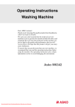
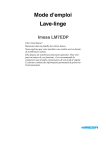
Use and Care Guide Drying cabinet ASKO DC 7171 Dear ASKO customer! Congratulations on your excellent product choice and welcome to the Asko family. A global family with its roots in Scandinavia. Cleaning results, design, environmental impact on nature and home, user friendliness, low consumption of time, energy and water, a long life span, reliability.... Good appliances should include all of these. And this is what we try to give you. When you buy an ASKO product, we want you to feel assured that the inside is as good as the outside and that the ethics and morals on which we built this machine are just as high as the quality and performance you get from it. That is what Scandinavian quality is all about. In order to get the best possible results from your machine and all its functions, please read this Use and Care Guide before using the machine for the first time. And if you have any questions, please do not hesitate to call us or contact us via our web site. Best regards from Scandinavia and the people at Asko. Contents Safety Instructions . . . . . . . . . . . . . . . . 4 Symbols . . . . . . . . . . . . . . . . . . . . . 4 Important points about safety . . . . . 4 Description of the drying cabinet . . . . 5 Control panel . . . . . . . . . . . . . . . . . . . . . 6 Where to install it. . . . . . . . . . . . . . . . . . 7 Electrical requirements . . . . . . . . . . . . . 8 User’s responsibility . . . . . . . . . . . . 8 Electrical connection . . . . . . . . . . . . 8 Ventilation alternatives . . . . . . . . . . . . . 9 Evacuation by ventilating the room where the drying cabinet is installed. . 9 Connection to the evacuation duct . . . . 10 Installation . . . . . . . . . . . . . . . . . . . . . . 12 Unpacking . . . . . . . . . . . . . . . . . . . 12 Complete delivery includes: . . . . . 12 Recommended tools . . . . . . . . . . . 12 Placing the door the other way round. . . . . . . . . . . . . . . . . . . . . . . 13 Horizontal adjustment . . . . . . . . . 14 Mounting . . . . . . . . . . . . . . . . . . . . 14 Assembly in the mounting unit 15 Connect Ventilation . . . . . . . . . . . . 17 Electrical connection . . . . . . . . . . . 17 Final check . . . . . . . . . . . . . . . . . . 18 How to use the drying cabinet . . . . . . 19 Starting . . . . . . . . . . . . . . . . . . . . . 19 Setting pause and restart . . . . . . . 19 Interrupting the drying. . . . . . . . . . 19 Choosing where to place the washing . . . . . . . . . . . . . . . . . . . . . 19 Some advice for users . . . . . . . . . 20 Setting the temperature selector knob . . . . . . . . . . . . . . . . . . . . . . . 21 Care. . . . . . . . . . . . . . . . . . . . . . . . . . . . 22 Cleaning . . . . . . . . . . . . . . . . . . . . 22 When the drying cabinet is not in use . . . . . . . . . . . . . . . . . . . . . . 22 Trouble Shooting . . . . . . . . . . . . . . . . . 23 Servicing . . . . . . . . . . . . . . . . . . . . . . . 24 Technical information . . . . . . . . . . . . . 25 Technical characteristics . . . . . . . . 25 Evacuation/Air intake . . . . . . . . . . 25 Energy consumption and drying time . . . . 25 Manufacturing standards. . . . . . . . 25 Air gap left during mounting . . . . . 25 Personal notes . . . . . . . . . . . . . . . . . . . 26 This Use and Care Guide This Use and Care Guide, for the drying cabinet describes: how it functions how to use it and also includes instructions for installation maintenance Date: November 2005 3 Safety Instructions Read this manual very carefully and follow the instructions provided. Especially important information is indicated by the accompanying symbols and text WARNING or ATTENTION. Symbols WARNING Indicates a risk of personal injuries, danger to life or serious damage to the product if the instructions are not followed. ATTENTION Other important remarks Advice and instructions about the best way to use the product and avoid operating disorders. Important points about safety The following advice and warnings have been drawn up, so that you may avoid both misusing the drying cabinet and the risk of unnecessary accidents. So read the following through very carefully before installing and using the drying cabinet. The drying cabinet should be installed or kept in storage indoors. Follow Asko’s recommendations concerning repairs and spare part replacement. Read this Use and Care Guide before using the drying cabinet. If a softening agent or antistatic substance is used, the manufacturer’s instructions concerning the utilisation of the product should be followed. Do not dry articles of clothing or similar items which have just been treated with petrol or some other volatile and inflammable agent. This can result in the build up of an explosive mixture of gases. Do not use heat in the cabinet for products containing foam rubber or similar material. Follow the manufacturer’s washing and drying instructions for such products very carefully. Do not allow children to play in or on the drying cabinet. Keep an eye on children when they are in the immediate vicinity of the cabinet. Keep the area around the evacuation duct free from dust and dirt. Keep this Use and Care Guide in a safe place so that it will always be at hand for future reference . 4 Regularly clean the inside of the drying cabinet. Description of the drying cabinet 1 2 9 X DC XXX 3 4 10 11 5 6 12 7 8 1. Sleeve coupling 9. 2. Appellation 10. Door 3. Hanger hooks 11. Door hanging bar for light items 4. Identification plate (inside) 12. Glove hangers 5. Upper hanging section 6. Middle hanging section 7. Lower hanging section 8. Shoe rack Control panel 5 Control panel 1 6 2 1. Temperature setting 2. Timer 3. START button (only certain markets) 3 Where to install it If the drying cabinet is to be installed, connection to an exhaust ventilation duct must be available, where it is to be located. There should be an earthed plug-in electric outlet socket within a distance of 2 metres from the upper part of the drying cabinet. The drying cabinet has a 2 metre long earthing cable with a plug connected to it. If the socket is not placed as mentioned above, the position of the drying cabinet should be adjusted so that no extension cable needs to be used. The electric socket should be easily within reach, after the drying cabinet has been installed. This should be taken into account even in the event of the drying cabinet being inbuilt into joinery or similar fittings. See also the section ’Electrical installation’. The floor should be able to stand the weight of the cabinet, approximately 60kg. The floor should be level with a slope of a maximum of 2.5cm beneath the cabinet. The drying cabinet is only intended to be placed indoors at a temperature above 0° Celsius. The drying cabinet must not be installed in a place where high pressure water is used for cleaning. Installation dimensions 595 mm 640 mm 1730 mm 610 mm 7 Electrical requirements User’s responsibility It is the responsibility of the user to contact a qualified electrician if the electric outlet socket is not easily accessible as laid down in this manual WARNING Connect the cabinet to an earthed outlet socket Do not remove the earth connection Do not use an adapter Do not use an extension cord Electrical connection The drying cabinet should be connected to the 230 Volt single-phase 50 Hz. mains supply, by an earthed wall socket. The electric socket should be installed and earthed in accordance with regulations in force. The drying cabinet is delivered complete with connections, including a 2 metre long cable with an earthed plug. Do not change the flexible cord and plug which come with the drying cabinet. If the plug is not adapted to the electric socket, this problem should be put in the hands of a qualified technician. 8 The drying cabinet should be connected with the provided connector cable and must not be permanently connected! The electric socket should be placed in such a way that the plug can easily be pulled out whenever necessary. Check that mains supply complies with the data on the identification plate and also that the main lead is earthed in the correct fashion, according to standards in force. We recommend that the main lead be provided with an earth fault contact breaker. The connection must have its own group of fuses. The manufacturer declines all responsibility for any consequences if the electrical connection is not made in the manner laid down in this Use and Care Guide. Ventilation alternatives There are two ways of evacuating humid air: Evacuation by ventilating the room where the drying cabinet is installed. Connection to the evacuation duct (exhaust air outlet) Evacuation by ventilating the room where the drying cabinet is installed. Do not hesitate to open doors or windows in the room for optimum ventilation. The ventilation pipe must reach the outside of the cabinet mounting unit. In the case of an inbuilt drying cabinet, exchange the flexible ventilation hose delivered with the cabinet (only certain markets) for a rigid ventilation pipe of 100 mm in diameter. Be sure that there is a good supply of air to the drying cabinet air intake orifice. The distance between the top edge of the pipe and the ceiling should not be less than 300 mm. 1. Humid air out 2. Air intake Ceiling Minimum 300 mm Ceiling 1 Minimum 300 mm 1 2 Evacuation by ventilating the room where the drying cabinet is installed. Free-standing drying cabinet 2 Evacuation by ventilating the room where the drying cabinet is installed. Drying cabinet inbuilt in customised mounting unit. 9 Connection to the evacuation duct When the cabinet is on, 45 m³ of humid air are evacuated per hour. So make sure that air can penetrate into the room to replace the humid air given off by the drying cabinet. ATTENTION The drying cabinet must not be connected to the fireplace chimney The drying cabinet can be connected to the evacuation duct in two ways With a draught limiter The exhaust air duct valve is replaced by a draught limiter (included in the delivery). See also the section ’Connect Ventilation’ page 14. Do not assemble the ventilation duct valve inside the drying cabinet 6 4 1. Humid air out 2. Hose 3. Sleeve coupling 4. Draught limiter 5. Air intake 6. Ventilation duct valve 1 5 2 3 The drying cabinet is connected to the evacuation duct with a draught limiter 10 Permanently installed and connected to the evacuation duct (only certain markets) ATTENTION Only the evacuation hose delivered with the cabinet must be used. (For the markets where such an article is included) When the drying cabinet is permanently connected to the evacuation duct, the whole room is ventilated by way of the drying cabinet. The exhaust air duct valve is replaced by an insert (not included). See also the section ’Connect Ventilation’ page 14. Do not assemble the ventilation duct valve inside the drying cabinet 3 3 1. Insert 2. Air intake 3. Ventilation duct valve 1 2 The drying cabinet permanently installed and connected to the evacuation duct 11 Installation Unpacking WARNING The cabinet can easily tip over since it is not yet solidly screwed into place. At least two people shoul manipulate the cabinet. Take off all the packing material; do not use a sharp tool which could damage the product. Check that the drying cabinet has not been damaged during transportation. The distributor should be notified of any damage during transportation within 7 Complete delivery includes: WARNING The packing material such as plastic or frigolite should be kept out of children´s way. Be attentive to the isk of small children suffocating when they come into contact with plastic material. days. After unpacking, check that the drying cabinet is free from defects. The distributor should immediately be notified of any damage, defects or even missing parts. Check that all the safety devices used for transportation have been removed before the drying cabinet is connected. Recommended tools The cabinet with the fan unit Bubble level Flexible hose for ventilation (only certain markets) Tape measure Hand drill Sleeve coupling with 2 attachment screws Screw driver (Phillips) Draught limiter (only certain markets) An 8 mm diameter drill bit Attachment screws (2 screws, washers and protective caps) for firmly fixing the cabinet to the wall Pencil Protective gloves (if supplied) Allen wrench and protective caps for the adjustable feet The Use and Care Guide for installation and utilisation 12 Placing the door the other way round The door can be hung on its hinges on the left or the right. 1. Lay the drying cabinet on its back side. 2. Disengage the hinge pin of the bottom hinge (1) and lift the door off. 3. Take off the plastic plug and press it right down on to the bottom hinge on the opposite side. 4. Disengage the hinge pin of the upper hinge (2) and place it on the opposite side. 5. Completely unscrew the glove hangers on the inside of the door and turn them 2 WARNING Pay attention to the risk of accidents due to the weight. At least two people should manipulate the drying cabinet. completely around. The glove hangers are fastened into place with four screws. 6. Rotate the door, fit it into place and fix it firmly by means of the lower hinge pin (1). 1 13 Horizontal adjustment 1 1. Lift out the shoe rack. 2. Control that surfaces are horizontal by placing a bubble level parallel to the walls and parallel to the back and the door. 3. Use the Allen wrench provided, and correct the position of all four adjustable feet through the holes in the base plate of the drying cabinet (use pliers if necessary). 4. Press the four protective caps down firmly into the holes. 2 1. Shoe rack 2. Bubble level 3. Allen wrench 3 Mounting 1. Take out the upper hanging section and mark the centres of the holes on the wooden strip (see the section “Installing in the cabinet mounting unit”) or on the wall behind the drying cabinet. 2. Pre-drill the holes in the spacer bead for the attachment screws. WARNING Since the cabinet is very heavy, there is a risk that it may topple forward. The cabinet should not be used without being screwed to the wall. 3. Fix the cabinet in place using the provided screws with their matching washers. 4. In the same way, fix the protective caps provided over the screw heads. 14 1. Pre-drilled hole 2. 2 attachment screws with washers 1 2 Assembly in the mounting unit 1. Keep the adhesive tape on the door until the drying cabinet is in place. Place the cabinet so that its front is properly aligned with the cabinet mounting unit. 2. Plug the connection cord into the socket and take care to be sure that the cord is not stuck and can easily be unplugged. 3. Take off the adhesive tape and open the door. Draw out the upper hanging section. Measure and note down the distance between the back wall of the drying cabinet and the wall behind the drying cabinet. See figure Measurement ’A’. 4. Mark the position of the holes on the back wall with a pencil. 5. Push back the hanging section, shut the door and hold it in place with adhesive tape. Pull out the entire drying cabinet. 6. Use a wooden strip of thickness “A”, according to point 3, as a spacer. The wooden strip must: 1 a) be divided into two parts to allow free passage of air behind the drying cabinet. Their length should be ~150 mm Place the drying cabinet so that its front fits well into the cabinet mounting unit. b) be at least 10 mm thick. 2 1. Minimum air gap 10 mm between drying cabinet and mounting unit (above and behind the drying cabinet) 2. Tape measure 3. Assembly holes 4. Drying cabinet back wall 5. Wall behind the drying cabinet A 3 4 5 15 7. Fix the two parts of the wooden strip in place using two screws, each of them screwed into the wall behind the drying cabinet, so that they correspond with the holes marked as in point 4. Use screws of a suitable length. 8. Push back the drying cabinet into the mounting unit. Take off the adhesive tape holding the door and check that the wooden strip is in place on the back wall of the drying cabinet. Also check that the front part of the drying cabinet fits well into the cabinet mounting unit. 9. Adjust the position of the drying cabinet horizontally according to the instructions in the section ”Horizontal adjustment” and screw the drying cabinet firmly down into place according to the instructions in the section ”Mounting” on page 12. 1 3 4 ~150 mm The cabinet mounting unit with assembled wooden strip, divided into two parts, to allow free passage of air 2 16 1. Attachment screws 2. Hole marking 3. Air flow 4. Wooden strip (in two parts) ATTENTION Check that the wooden strips are properly and firmly in place in the back wall and also that the assembly screws do not obstruct the assembly holes in the drying cabinet. Connect Ventilation If the dr ying cabinet is inbuilt, the sleeve coupling is mounted through the ventilation vent in the top part of the cabinet mounting unit after the drying cabinet has been assembled in its final position. The sleeve coupling is designed to be securely screwed into the top cover plate of the drying cabinet by means of two screws.There are predrilled holes in the sleeve coupling and the top cover plate. Attachment screws are delivered with the product. 1. Place the sleeve coupling over the hole in the top cover plate of the drying cabinet, matching the screw holes and firmly screw down the sleeve coupling. 2. If the drying cabinet is inbuilt, connect the rigid ventilation pipe. If not, the flexible hose, delivered with the product, (only certain markets), should be pressed securely into place. Consult the earlier section ’Ventilation’, on page 9. 1 1. Sleeve coupling Electrical connection Consult the earlier section ’Electrical requirements’, on page 8. 17 Final check 1. Check that all parts are mounted. If not - go through all the steps once more. 2. Check that no packing material is left lying around. 3. Use a mild washing up product with warm water and wash the drying cabinet inside and out. Dry it carefully. See also the section ’Care’ further on in the manual. 4. Put the plug in and press on ’START’ (only certain markets). If the cabinet is not giving out any heat, even though the temperature selector knob is activated and the fan is functioning, turn the temperature selector knob back to zero and wait 30 minutes. Then try again by first putting the temperature selector knob on ’Normal’ (or the corresponding symbol) and then start the fan by turning on the time selector knob. See also the section ’Troubleshooting’. 5. Read the section ’How to use the drying cabinet’ further on in the manual. 6. Put the temperature selector knob on ’Normal’ position (full heat) or on the corresponding symbol (see figure) and the time selector knob on approximately 20 minutes. If the drying cabinet does not start, check the following: - that the door of the drying cabinet is shut properly - that the temperature and time selector knobs are activated. - that the ’START’-button has been properly pressed in (only certain markets). - that the drying cabinet is connected to the mains electricity supply. - that the fuse is in working order 7. When the drying cabinet has been on for 5 minutes, open the door and feel if it is giving out heat. 18 Symbol for ”Normal” (full) heat How to use the drying cabinet Starting 1. Place the articles to be dried in the drying cabinet and shut the door. See also the section ’Choosing where to place the washing’. Interrupting the drying Open the door and turn the time selector knob back to ’0’.’ 2. Set an appropriate temperature and drying time. See the section ’Setting the temperature selector knob’. 3. Press on the START button (only certain markets). Setting pause and restart Pause: Open the door Restart: Shut the door and press on the START button (only certain mar kets) Choosing where to place the washing In the cabinet there are three sections with hangers.Every section has a number of rods on which to hang the washing. The optimised hanging system has extensible hangers. This system lightens the work for those who hang up the washing and spares both their back and shoulders. Hang the articles in the drying cabinet according to how much room they take up - not according to their weight. For optimum efficiency - do not lay articles flat on the upper hanging section. Long clothes nearest to the walls of the cabinet and shorter ones towards the If you have made a pause in the drying process, when it starts again, the drying cabinet carries on from the position it was at when the drying cycle was interrupted. If you want to completely stop the set drying cycle, the time selector knob is put back to ’0’. WARNING Read the safety instructions on page 4 before using the drying cabinet centre. By hanging the washing in this way the most efficient drying results are attained. Turn up the two lower hanging sections if long clothes are to be dried. Hang gloves, caps, scarves and suchlike on the hanging bars on the inside of the door. Draw forward the upper hanging section hanger hooks in order to hang up the washing more easily. Put it back when it is not being used. 19 Do not overload the drying cabinet. The washing will become creased and drying uneven. Instead, leave a certain distance between items of washing, if this is possible If there is a risk that certain washed items give off their colour, free space should be left around them. Avoid drying thick clothes at the same time as lighter articles for they have completely different drying times. Remember not to hang knitted articles. These can be needlessly stretched when they are heavy with water. When the drying cabinet is cold, it may happen that the sealing strip on the door does not close completely. However, this is fully compensated for when the cabinet is in operation since, with warmth, the sealing strip expands. The figure shows the airflow inside the cabinet Some advice for users Setting the controls Drying Set the temperature and the time selector knobs for the most delicate articles to be dried. Always follow the washing instructions on clothes if such instructions are available. The temperature is changed by means of the temperature selector knob which can be turned in both directions. If a softening agent or antistatic substance is used, the manufacturer’s instructions concerning the utilisation of the product should be followed. Take out washing that is already dry. This reduces drying time for the washing that is left. 20 Setting the temperature selector knob Do not use any heat when drying articles of clothing filled with foam rubber or similar material. 3 1 The temperature selector knob regulates heat by means of a continuous scale of temperature positions from no heat at all till normal position with full heat. 2 Setting 1 2 3 Type of fabric Foam rubber products, plastic, clothes which are sensitive to heat Temperature Only fan Sportswear, underwear, shirts, blouses, silk garments, washable knitted products Low Sturdy working clothes, denim, cotton garments, training sweaters (cotton) Normal 21 Care Cleaning High-pressure cleaning should not be used! The walls of the cabinet should be cleaned with a mild soap solution on a damp cloth. Dust frequently gathers round the air intake orifice on the upper part of the cabinet. This can disturb the way the cabinet functions which can, in turn, lead to a breakdown. To avoid this problem, the air intake orifice and the top of the cabinet should be vacuum-cleaned at least once a year or more often depending on the environment the cabinet is placed in. When the drying cabinet is not in use When the cabinet is not in use for a short or long time Always pull out the electric plug. When the cabinet must be moved 1. Pull out the electric plug. 2. Secure the door with strong adhesive tape. 22 Trouble Shooting Before calling on outside help, first try to put the trouble right with the help of the indications below. Trouble Cause What to do The washing has The fuses controlling the drying Check not dried as well cabinet have tripped. as expected The temperature and/or time se- Control the settings lector knobs have not been correctly set. The drying cabinet has been used To work normally, the drying cabinet must obligatorily be in a room where the temperature installed in a room where the is lower than 0° C temperature is above 0°C Washing has been badly spun or Check what is hanging in the is still very wet. drying cabinet. Has the washing been hung in the See the section ’Choosing right way? where to place the washing’. Has the temperature selector Control the settings. knob been set too low? Are the ventilation pipe/hose too long? The drying ca- Is it plugged in? binet is not giving out any heat Is the fuse in working order? even though the temperature se- Is the right fuse being used? lector knob is activated. Is the door of the drying cabinet shut? They should not be more than 1 metre long. Check. Check. Change to a more resistant fuse. Check. Has the START button been Press on the button once more. properly pressed in (only certain markets)? Has the time selector knob been Check. set? The temperature limiter has been Turn the time selector knob back to ’0’ and wait 30 minutes. tripped. Then try again by activating the temperature selector knob and, after that, start the fan by turning on the time selector knob. The temperature limiter is faulty Contact Customer Service. 23 Servicing Before you contact customer service, you should find out the designation of the model, its type and its serial number. The designation of the model is inscribed on the cabinet control panel. The type and the serial number are inscribed on the identification plate which is placed on the inside of the cabinet. 1 X DC XXX 2 3 ���������������� ��������������������� ���������������� 4 5 Identification plate 24 1. Model 2. Identification plate (inside) 3. Article number 4. Serial number (12 figures) 5. Type Technical information Technical characteristics Capacity: approximately 3.5 kg washing (cotton) Water removal rate : 17.5 grams per minute Electricity connection: Single phase 230 V, 50-60 Hz Motor: 35 W Heating element power consumption: 1500 W Protection against overheating: Yes Timer: Adjustable, up to 4 hours Hanging length: 16 metres Dimensions: Height 1730 mm Adjustable between 1720 mm and 1745 mm. Width 595 mm. Depth 610 mm, Weight: ~60 kg Colour: White, titanium or grey Sound level: maximum 58 dB (A) Evacuation/Air intake When the cabinet is on, 45 m³ of humid air are evacuated per hour. Energy consumption and drying time Spun-dried washing *) Setting Energy consumption Drying time Temperature Position 2 (Low) 0.6 kWh/kg washing approx. 180 minutes 45 °C Position 3 (Normal) 0.7 kWh/kg washing approx. 120 minutes 65 °C *) Given values may vary depending on the rotation speed during spin-drying Manufacturing standards See the identification plate Air gap left during mounting Minimum 10 mm between drying cabinet and mounting unit (above and behind the drying cabinet). 25 Personal notes 26 Gematech Innovation Art. Nr: 427000389 Rev. 01 We reserve the right to make alterations. Printed on environment friendly paper, complying with the requirements of Miljöförbundet (Swedish Environmental Organisation) and Naturskyddsföreningens (Swedish Association for nature conservancy).