1
User Manual
for the
COMM-TEC EIB Gateway
CTG-KNX/IP (v1.0.1)
-1-
Table of contents
1
2
3
4
5
6
7
8
Introduction.....................................................................................................................................3
1.1 Aims?..........................................................................................................................................3
1.2 Role of the EIB installer ..............................................................................................................3
1.3 EIB from the AMX programmer’s point of view...........................................................................3
1.4 EIB details when using the Gateway ..........................................................................................5
Hardware ........................................................................................................................................6
2.1 Interfaces, Indication and Operating Devices.............................................................................6
2.2 Installation ..................................................................................................................................6
2.2.1 Connection Gateway – TCP/IP Interface............................................................................6
Programming ..................................................................................................................................7
3.1 Integrating the Module................................................................................................................7
3.2 Analyzing feedback signals ........................................................................................................8
3.3 The NetLinx module interface.....................................................................................................9
3.3.1 Commands for module .......................................................................................................9
Description .........................................................................................................................................9
3.3.2 Feedback from module .....................................................................................................11
Description .......................................................................................................................................11
3.3.3 Terminal Mode..................................................................................................................11
3.3.4 Channels and levels .........................................................................................................14
Data Types ...................................................................................................................................14
Appendix A – Sample program.....................................................................................................15
5.1 Notes EIB table.........................................................................................................................15
5.2 Notes for programming.............................................................................................................15
5.2.2 Example 2 - Structure of EIB table with SEND_COMMANDS..........................................17
5.2.3 Example 3 – Enter addresses from file.............................................................................18
5.2.4 Example 4 – Main program...............................................................................................19
Appendix B – EIB_Tools.AXI........................................................................................................20
Appendix C – Comparison with previous version .........................................................................21
7.1 Structure / Generation of filter table in gateway .......................................................................21
7.2 Controllling actuators................................................................................................................21
7.3 Feedback..................................................................................................................................21
Appendix D – What to do if it does not work?...............................................................................22
© COMM-TEC GmbH
Siemensstrasse 14
D-73066 Uhingen
Tel.: +49 (0)7161/3000-0
Fax: +49 (0)7161/3000-400
-2-
1
Introduction
1.1
Aims
The software module is being used to connect AVIT and AMX control systems to the "European
Installation Bus" EIB ("Instabus"). It provides an easy to use interface for developers to comfortably
access the
bus.
1.2
Role of the EIB installer
It can not be expressed strongly enough: when connecting to an EIB system, solid knowledge of the
EIB and close contact to experienced EIB installers is strongly recommended. A faulty set Reading
flag in an actuator, or a restrictively programmed line coupler can be really hard to find without good
analysis tools.
There is now way the Netlinx module is able to configure an EIB system. The package is used to
connect to a working EIB, and can access only those bus elements whose usage is permitted.
Because of that, it should be planned together with the EIB installers if all desired functions are
allowed to the bus components.
1.3
EIB from the AMX programmer’s point of view
Analog to AMX systems is the European Installation Bus – as the name implies – a bus system: all
components are in principle connected to the same wire and share the available bandwidth.
The bus itself is a 2-wire cable, used to supply 24VDC to the devices, as well as transferring data
between them.
Unlike AMX, the EIB system is a decentralized structure – there is no special master controlling the
communication, but any device can send data to any other device.
A sophisticated protocol ensures that only one device is sending at any time, and collisions are
avoided as much as possible.
All communication happens in the form of telegrams. A telegram is a data packet, that consists of the
following parts:
• Source ID – Hardware address of the transmitting device
• Destination address – Group address of the receiving devices
• User data
A telegram can be transmitted to several destination devices at the same time, i.e. to switch off all
lamps in a room simultaneously.
So there is a fundamental difference between both source and destination addresses:
A source address is a hardware address, describing the device that is transmitting the telegram.
A destination address is a group address, describing the function to be influenced.
Thus each device connected to EIB has exactly one hardware address, but may have several group
addresses.
Furthermore, it is possible and common for several devices to respond to the same group address.
The EIB installer assigns both address types – the hardware addresses describing type and number
of utilized devices and assigned during planning and installation. Hardware addresses are of no
concern for the gateway.
The much more important addresses for AMX are the group addresses.
They define the functions an EIB installation can perform. So functions are simply used by
transmitting specified values to group addresses.
-3-
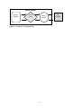
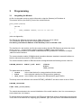
NetLinx Master
NetLinx
Program
Virtual
Device
NetLinx
Module
Figure 1 – Process of Communication
-4-
EIB
Gateway
1.4
EIB details when using the Gateway
CTGKNX/IP
CTGKNX/IP
In principle, the EIB gateway CTG-KNX/IP is a normal EIB device, and can therefore be connected at
any location to the EI bus. Unlike simple actuators or sensors it can be responsible for a large amount
(up to 3000) of group addresses – a normal dimmer for example, just reacts to four addresses.
So one must be very careful to ensure that the gateway has a real chance to react to all bus
telegrams of interest. Especially when using line couplers, solid planning is absolutely necessary. The
following points should be seriously considered:
On the one hand all telegrams should reach the gateway. If line couplers are inserted between
gateway and controlled components, their filter tables are to be programmed in such a way that all
relevant telegrams are really passed through.
On the other hand the EI bus couplers are slow – upon receipt of a telegram, an EIB device needs
some time until the next telegram can be accepted. Especially scene modules can generate a flood
of telegrams, which are transmitted to all actuators participating in the scene.
Because these are usually different devices, the down time of the bus couplers does not matter –
each coupler has enough time to recreate before the next telegram gets received.
The situation with the gateway is different: normally all participating group addresses of a scene are of
interest – the gateway needs a recovery time and can read all telegrams, even with high bus load.
However, with the activation attention has to be paid, that the activated actuators are given enough
time!
-5-
2
Hardware
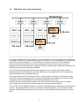
2.1
Interfaces, Indication and Operating Devices
Connections :
230 V
EIB
RJ45
LEDs :
Busspannung
Bustelegramm
TX
RX
Betrieb
Prog.-LED
Push-button : Prog.-Key
2.2
2.2.1
flashes when bus voltage drops below 15V
indicates telegrams on the EIB
indicates data transmission from Gateway to AVIT / AMX
indicates data transmission from AVIT / AMX to Gateway
is lightened when voltage feed is being impressed
flashes when the Gateway is being set to programming mode on
the EIB-side
sets Gateway to programming mode (on EIB-Side)
Installation
Connection Gateway – TCP/IP Interface
The Gateway is being connected to the network by a standard network cable.
-6-
3
Programming
3.1
Integrating the Module
At first, the program needs to get the information, what the Gateway’s IP-Address is.
This can be done by the Online_Event of the virtual Devices:
DATA_EVENT[vdvEIB]
{
ONLINE :
{
SEND_COMMAND vdvEIB,'IP=172.16.100.123'
}
}
(also see Appendix)
The Port for the Gateway has been set to 10002, which can not be edited.
The IP-Address will be set by the included gateway software.
On delivery, the Ethernet Address of the Gateway is set to 192.168.1.106.
The interface for the module, and for the communcation with the EIB-Gateway provides the virtual
device vdvEIB. Communication with the gateway is ONLY via the virtual device.
A complete documentation of available commands and string feedback is contained in chapter
„NetLinx module interface“.
The communication module (COMM module) translates between standard command interface on
NetLinx side and the protocol for EIB connection.
The communication module for EIB connection is integrated with the following source code line:
DEFINE_MODULE 'CTEIB7_mod' EIB7(
vdvEIB,
dvEIB,
lEIB_Value)
The parameters are as follows:
• vdvEIB
- is the virtual device for communication with the module
• dvEIB
- is the physical interface for EIB connection (gateway)
• lEIB_Value - is the central value array of the EIB actuators (type LONG!)
This Array hast to be defined in the section DEFINE_VARIABLE, and has to have a size of 3000:
DEFINE_VARIABLE
...
LONG lEIB_Value[3000]
...
The module also attends to the correct initialization of the serial interface, thus it is not necessary to
set the baud rate, for instance.
To access/analyze actuators on the bus, the EIB group addresses must be introduced to the program.
This is done in an external file, mapping group address, type, poll conjunction and additional features
-7-
on an „AMX number between 1 and 3000. Communication with the actuators concerned is only made
via this number.
This tabel is integrated with the following source code line:
#INCLUDE 'EIB_Table.axi'
An example for such a file and a sample program is contained in Appendix A.
In addition, the file EIB_Tools.AXI should be integrated to have easy access to commonly used
functions (see Appendix B).
#INCLUDE 'EIB_Tools.axi'
3.2
Analyzing feedback signals
All feedback signals should be analyzed in a Data_Event. One DATE_EVENT is being released for
each feedback signal – so there is exactly one feedback in DATA.TEXT ! In case of several feedback
signals, the same amount of Events will be released accordingly.
-8-
3.3
The NetLinx module interface
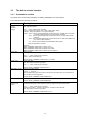
3.3.1 Commands for module
Commands to the module always take place per SEND_COMMAND to the virtual device.
The module knows the following commands:
Command
Description
ADD=<No>:
<Type>:
<GrpAdr>
[:Flags]
Add an EIB group address to list
Note: Flags are optional
DATE=<No>:
<Date>
<No> - 1_3000 = AMX number of actuator
<Type> - Actuator type (Switch, Dim4, 1Byte, 2Byte, 3Byte, 4Byte)
<GrpAdr> - EIB group address in 2 or 3 grouped display
<Flags> - EIS5 - value is reported additionally as ASCII float value. The EIB value is converted
according to EIS5 standard (only valid for 2Byte actuators)
- Time - value is reported additionally as ASCII time (hh:mm:ss) (only valid for 3Byte
actuators)
- Date - value is reported additionally as ASCII date (Caution: AMX format: MM/DD/YY)
(only valid for 3Byte actuators)
- PS – actuator is automatically polled with Start of AMX system
Flags are separated by commas
Examples:
SEND_COMMAND vdvEIB,’ADD=13:Switch:1/0/11’
SEND_COMMAND vdvEIB,’ADD=17:1BYTE:4/7/12:PS’
SEND_COMMAND vdvEIB,’ADD=45:2BYTE:3/0/11:EIS5’
SEND_COMMAND vdvEIB,’ADD=12:3BYTE:2/1/101:TIME,PS’
Setting the date
Note: Only valid for actuators type 3Byte
<No> - 1 … 3000 = AMX number of actuator
<Date> - date in format dd/mm/yy
DATE? <No>
Example: SEND_COMMAND vdvEIB,’DATE=17:14/08/06’
Inquiry date value
Note: Only valid for actuators type 3Byte
<No> - 1 … 3000 = AMX number of actuator
DEBUGON=<Level>
Example: SEND_COMMAND vdvEIB,’DATE?17’
Activating the debug reports
<Level> - (… upcoming …)
With activated debug report all actuators of the terminal are listed, which can be accessed via
EIB. This allows simple diagnostics.
DEBUGOFF
EIS5=<No>:
<floating point
value>
Example: SEND_COMMAND vdvEIB,’DEBUGON=1’
Deactivating the debug reports
Example: SEND_COMMAND vdvEIB,’DEBUGOFF’
Setting an EIS5 value
Converts a floating-point value mapped in ASCII into 2Byte EIS5 value before transfer.
<No> - 1 … 3000 = AMX number of actuator
<Floating Point Value> - number in the range of –671088,64 and 670760,96
Note: Only valid for actuators type 2Byte
Example: SEND_COMMAND vdvEIB,’EIS5=12:24,3’
-9-
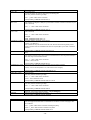
Command
Description
EIS5? <No>
Inquiry EIS5 value
Converts the 2Byte raw data into ASCII string with floating point
Note: Only valid for actuators type 2Byte
<No> - 1_3000 = AMX number of actuator
GET=<No>
GET? <No>
Example: SEND_COMMAND vdvEIB,’EIS5:12’
Inquiry of actuator value stored in the module
Note: Creates no telegram on EIB (for synchronization of master-to-master connection only use
POLL command)
<No> - 1 … 3000 = AMX number of actuator
POLL=<No>
POLL? <No>
Example: SEND_COMMAND vdvEIB, ’GET=17’
Inquiry current value of actuator (for synchronization of master-to-master connection only use
POLL command)
<No> - 1 … 3000 = AMX number of actuator
POLLDELAY=<Value>
Examples:
SEND_COMMAND vdvEIB,’POLL=17’
SEND_COMMAND vdvEIB,’POLL?17’
Set pause between (automatic) value inquiries
<Value> - 0-2 (default=1)
Note: 0 stands for very fast and should not be used, because otherwise the gateway would
create a high bus load. For installations with slow bus couplers (BCU1), the value 2 should be
selected.
SENDDELAY=<Value>
SET=<No>:<Value>
Example: SEND_COMMAND vdvEIB,’POLLDELAY=2’
Delay between commands to EIB. Value is the time in 1/10 sec. The value 0 deactivated the
delay
Set actuator
Note: Observe actuator type in value range! The module limits the value range automatically to
max valid range of the accessed actuator
<No> - 1 … 3000 = AMX number of actuator
<Value> - value to be set
STARTDELAY=<Value
>
Example: SEND_COMMAND vdvEIB,’SET=5:1’
Sets point in time, when the module is activated, time for booting of master.
<Value> - time in seconds (default = 30, value should not be changed)
STATE?
TIME=<No>:<Time>
Example: SEND_COMMAND vdvEIB,’STARTDELAY=40’
Output of current module status in terminal
Set current time
Note: Only valid for actuators type 3Byte
<No> - 1 … 3000 = AMX number of actuator
<Time> - time in format hh:mm:ss
TIME=<No>
Example: SEND_COMMAND vdvEIB,’TIME=8:13:15:00’
Inquiry of time
Note: Only valid for actuators type 3Byte
<No> - 1 … 3000 = AMX number of actuator
UPLOAD
VERSION
Example: SEND_COMMAND vdvEIB,’TIME?8’
Synchronizing internal tables – gateway
Writes the current internal table to gateway – only for debugging
Output of current module version on monitor
Example: SEND_COMMAND vdvEIB,’VERSION’
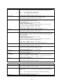
Command
Description
WHEN=<No>:<No2>
Definition of poll triggers
Note: The trigger is activated when the first address is accessed, not when changing a value
for an address.
<No> - 1_3000 = AMX number of actuator activating the polling
<No2> - 1_3000 = AMX number of actuator to be polled
Example: SEND_COMMAND vdvEIB,’WHEN=32:12’
- 10 -
3.3.2 Feedback from module
The feedback is always in STRING format.
The module can generate the following feedback:
String
Description
DATE=<No>:<Value
>
Feedback of date
Note: Is transmitted as ADDITIONAL feedback, if in actuator <No> the DATE flag is set.
<No> - 1 … 3000 = AMX number of actuator
<Value> - Date string in format MM/DD/YY (AMX display)
EIS5=<No>:<Value>
Example: DATE=17:08/14/06
Feedback of a value in ASCII floating point display. The actuator value to be coded according to
EIS5.
Note: Is transmitted as ADDITIONAL feedback, if in actuator <No> the EIS5 flag is set.
<No> - 1 … 3000 = AMX number of actuator
<Value> - floating point value (string) converted according to EIS5 specification
ERRORM=
SET=<No>:<Value>
Example: EIS5=12:20.25
Error message from gateway and/or bus.
The message are only for information.
Report of a value change
Notes: The feedback array (type LONG) is automatically updated, unchanged values are reported
as VAL = (see below).
<No> - 1 … 3000 = AMX number of actuator
<Value> - New value of actuator (raw data)
TIME=<No>:<Value>
Example: SET=8:1
Feedback of time
Note: Is transmitted as ADDITIONAL feedback, if in actuator <No> the time flag is set.
<No> - 1 … 3000 = AMX number of actuator
<Value> - Time string in format hh:mm:ss
VAL=<No>:<Value>
Example: TIME=18:09:55:30
Feedback of an unchanged value
(for instance after GET or POLL)
<No> - 1 … 3000 = AMX number of actuator
<Value> - Value of actuator
3.3.3 Terminal Mode
For implementation and diagnostics several monitor functions are available. The following commands can be
transmitted directly in monitor mode to the module. These commands are transmitted with SEND_COMMAND
to the virtual device.
To visualize the text outputs on the monitor it must be activated with command “MSG ON”, and the following
SEND_COMMAND <vdvDEV>, ‚‘DEBUGON=1‘ must be sent to the virtual device.
Capitalization is ignored during input; additional parameters (if available) are separated with a space (in this
documentation with “_”).
Naturally, in monitor mode also the commands of the regular command interface are available (i.e. ADD=,
SET=, etc.).
Acknowledgements/notes generated in this way serve only diagnostics und should be switched off during
runtime. Output messages are marked by the prefix “EIB”.
- 11 -
Command
Description
ADR_<Value>
Definition of output format of EIB group address
(Main/medium/sub group OR main group/sub group)
<Value> - 2/3
DEL_<Value>
Example: SEND_COMMAND vdvEIB,’ADR 3’
Delete actuator from table
<No> - 1 … 3000 = AMX number of actuator
HELP
/?
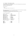
LIST
LIST_<Typ>
Example: SEND_COMMAND vdvEIB,’DEL 3’
Output of available monitor commands
Example: SEND_COMMAND vdvEIB,’HELP’
List all entered actuators with AMX number, EIB group address, current value, set flags (if
applicable) and resulting additional acknowledgement values
List sum of individual types, sum of all actuators
Example: SEND_COMMAND vdvEIB,’LIST’
List all entered actuators with AMX number, EIB group address, current value, set flags (if
applicable) and resulting additional acknowledgement values.
Sum of all actuators of one type
<Type> - data type, where
SW or SWITCH – 1Bit actuators
D4 or DIM4 – 4Bit actuators
1B or 1BYTE – 1Byte actuators
2B or 2BYTE – 2Byte actuators
3B or 3BYTE – 3Byte actuators
4B or 4BYTE – 4Byte actuators
LIST_<No>
Example: SEND_COMMAND vdvEIB,’LIST 1B’
List ONE actuator (AMX number) with EIB group address, current value, set flags (if applicable)
and resulting additional acknowledgement values
<No> - 1 … 3000 = AMX number of actuator
Example: SEND_COMMAND vdvEIB,’LIST 17’
- 12 -
Command
Description
LIST_<No>-<No2>
List actuators in the range of <No> to <Nr2> (AMX numbers) with EIB group address,
current value, set flags (if applicable) and resulting additional acknowledgement values
<No> - 1 … 3000 = AMX number of actuator (start)
<No2> - 1 … 3000 = AMX number of actuator (end)
LIST_FLAGS
LIST_LOAD_[<Filename>]
LIST_POLL
LIST_SAVE_[<Filename>]
LIST_SUM
LIST_WATCH
LIST_GAPS
Example: SEND_COMMAND vdvEIB,’LIST 17-24’
List ALL actuators with assigned flags in table with EIB group address, current value, set
flags (if applicable) and resulting additional acknowledgement values
Example: SEND_COMMAND vdvEIB,’LIST FLAGS’
Reads an entry in table written with LIST_SAVE from CF and back.
The current table is replaced with the read one.
File name is optional.
If no file name is specified, the default file name is used.
Default file name: EIBTableNX.TXT
(In monitor connection with master the already available files on CF can be listed by
entering “list” (no SEND_COMMAND to virtual device!!!).)
Example: SEND_COMMAND vdvEIB,’LIST LOAD’
Example: SEND_COMMAND vdvEIB,’LIST LOAD MyTable.txt’
List all poll triggers with AMX number and EIB group address
Example: SEND_COMMAND vdvEIB,’LIST POLL’
Writes the current EIB table, including poll trigger, as text file on CF. This file can be edited
with simple text editor. The entries correspond with the structure of the regular table. Thus
a table can be buffered, modified (i.e. delete or add actuators) and finally reconstructed
with LOAD (see above)
File name is optional.
If no file name is specified, the default file name is used.
Default file name: EIBTableNX.TXT
(In monitor connection with master the already available files on CF can be listed by
entering “list” (no SEND_COMMAND to virtual device!!!).)
Example: SEND_COMMAND vdvEIB,’LIST SAVE’
Example: SEND_COMMAND vdvEIB,’LIST SAVE MyTable.txt’
List sum of all types, sum of all actuators
Example: SEND_COMMAND vdvEIB,’LIST SUM’
List currently observed actuator with EIB group address, current value, set flags (if
applicable) and resulting additional acknowledgement values
Example: SEND_COMMAND vdvEIB,’LIST WATCH’
List free (unused) AMX numbers
SEARCH
<Groupaddress>
Example: SEND_COMMAND vdvEIB,’LIST GAPS’
Search for EIB group address
Note: Here 2 and 3 grouped mapping is accepted.
(Caution: The addresses 7 / 715 and 7 / 2 /203 are i.e. identical EIB group addresses)
STATUS
Example: SEND_COMMAND vdvEIB,’SEARCH 1/0/101’
List general status information for:
A;X hardware, EIB module, gateway, active EIB table
Example: SEND_COMMAND vdvEIB,’STATUS’
Command
Description
UPLOAD
Write table to gateway
WATCH <No>
Example: SEND_COMMAND vdvEIB,’UPLOAD’
Activate observation function for actuator. All value changes are recorded on monitor with
EIB group address, current value, set flags and resulting additional acknowledgement
values.
<No> - 1 … 3000 = AMX number with 0 standing for deactivation of observation
WATCH_OFF
Example: SEND_COMMAND vdvEIB,’WATCH 12’
Deactivate observation function for actuator
- 13 -
3.3.4 Channels and levels
All addresses are available as channels. The current value is displayed on the corresponding channels of the
virtual device. For value report “0” the channel is OFF, for all other values ON.
Channel
1 … 3000
3001
3002
Description
Display of values (irrespective of EIB type)
Gateway was detected, module ready for ADD = commands
Gateway and module function correct
The first 200 addresses (actuators in EIB table) are available as levels. For every value change the current
value is transmitted as level to the program, for instance to control a bar graph.
Level
Description
lay of values of first 200 group addresses (irrespective of EIB type)
4
Data Types
‘Switch‘
‘4 Bit‘
‘1 Byte‘
‘2 Byte‘
‘3 Byte‘
‘4 Byte‘
‘Text‘
‘HEXText‘
-
Value ‘0‘ or ‘1‘
(e.g. OFF – ON)
Value ‘0‘ to ‘15‘
(e.g. relative dimming – direction, interval)
Value ‘0‘ to ‘255‘
(e.g. value absolute)
Value ‘0‘ to ‘65535‘ (e.g. floating point value in EIS5 Notation)
3 Byte
(e.g. Date or Time)
4 Byte
1 to 14 ASCII Characters, String automatically filled with spaces
1 to 14 Byte Hexvalue in ASCII-Notation
- 14 -
5
Appendix A – Sample program
5.1
Notes EIB table
All actuators to be switched/set/controlled are to be introduced to the gateway. This is achieved with a table
structure.
If this table is generated with a help file (i.e. ‘EIB_Table.AXI’) it must only be observed, that all entries are
edited, meaning the last Switch_Case command (default:) is really edited last. There is to be no gap in the
counter. For the entries itself the order is irrelevant.
Recommendation: Use the version with help function (example 1, see below). In this version less typing errors
will occur and the compiler can perform several checks.
Poll triggers are only entered, if the polling and polled addresses are already entered. We recommend entering
the poll triggers at the end.
Alternatively, a table may be loaded from the master’s Compact Flash. The syntax is identical with
SEND_COMMAND “ADD=”. The send command and device address are omitted (example 3, see below).
5.2
Notes for programming
Predefined functions are available for control to generate the SEND_COMMANDs for the virtual device.
We recommend to always use the functions of the EIB_Tools.AXI include file instead of directly using
Send Commands (Appendix B). Less typing errors will occur and the compiler can perform several
checks.
- 15 -
5.2.1 Example 1 – Structure of EIB table with functions from EIB_Tools.AXI
Start delay, module reports ready for ADD
Start
Set light 1
Set light 2
Set light 3
Lights, status
Light 2 status
Light 3 status
Light scenes 1+2
Light scenes 3+4
Shutters, up/down
Shutters, blinds
Dimmer, on/off
Dimmer relative
Dimmer absolute
Dimmer value
Analog value 2
Time
Date
Polltrigger
Polltrigger
Polltrigger
Polltrigger
Polltrigger
Polltrigger
- 16 -
5.2.2 Example 2 - Structure of EIB table with SEND_COMMANDS
Start delay, module reports ready for ADD
Start
Set light 1
Set light 2
Set light 3
Lights1 status
Light 2 status
Light 3 status
Scenes 1+2
Scenes 3+4
Shutters up/down
Shutters blinds
Dimmer, on/off
Dimmer relative
Dimmer absolute
Dimmer read
value
Analog value
Analog value
Time
Date
Polltrigger
Polltrigger
Polltrigger
Polltrigger
Polltrigger
Polltrigger
- 17 -
5.2.3 Example 3 – Enter addresses from file
The address table can be read and generated from file on CF card. The reading of the file can for instance be
started in the ONLINE section of the interface.
(Description see chapter “Monitor mode”)
Note: Comments at the end of a line must be separated by at least one space und are initiated – corresponding
with programming – with “//”.
Only one command per line is permitted. Leading spaces are ignored.
Lines starting with “//” are completely treated as a comment and not edited by the controls.
Set light 1
Set light 2
Set light 3
Light 1 status, inquire at start
Light 2 status, inquire at start
Light 3 status, inquire at start
Scene 1+2
Scene 3+4
Shutters up/down
Shutters blinds
Dimmer , on/off
Dimmer relative
Dimmer absolute
Dimmer read value
Analog value, inquire at start
Analog value
Time, inquire at start
Date, inquire at start
Polltrigger
Polltrigger
Polltrigger
Polltrigger
Polltrigger
Polltrigger
- 18 -
5.2.4 Example 4 – Main program
feedback array for max 3000 addresses
Light 1 ON
Analog actuator 50%
Dimmer brighter
feedback for light 1 (see EIB table)
// Key illuminated if actuator >= 50%
- 19 -
6
Appendix B – EIB_Tools.AXI
We recommend not to use the send commands directly, but always utilize the functions of this include file. The
compiler has the opportunity to avoid typing errors already during compiling. Additional typing is avoided.
This file also provides absolute terms for relative dimming:
The following functions are available in file EIB_Tools.AXI for programming:
EIBSet (<Virtual Device>,<AMXNo>,<Value>)
Function:
Sets actuator <AMXNo> to <Value>
The module limits the value range automatically to the maximum range of the selected actuator.
Example:
EIBSet (vdvEIB,13,1)
EIBGet (<Virtual Device>,<AMXNo>)
Function:
Gets the value of actuator <AMXNo> to <Value> stored in module
Example:
nVAL = EIBGet (vdvEIB,13)
EIBPoll (<Virtual Device>,<AMXNo>)
Function:
Polls the actuator <AMXNo>
Example:
EIBPoll (vdvEIB,13)
EIBAdd (<Virtual Device>,<AMXNo>,<Type>,<Group Address>,<Flags>)
Function:
Adds entry to EIB table (description of parameters see above)
Example:
EIBAdd (vdvEIB,13,eib2Byte,’1/0/206’,”eibPollstart”)
EIBWhenPoll (<Virtual Device>,<AMXNo1>,<AMXNo2>)
Function:
Adds a poll trigger. Value report from <AMXNo1> triggers polling on <AMXNo2>.
Example:
EIBWhenPoll (vdvEIB,13,20)
- 20 -
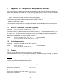
7
Appendix C – Comparison with previous version
The general operation of hardware and software has not changed. A filter table has still to be generated and
loaded into the gateway. Via this filter the incoming and outgoing telegrams are filtered. The control of actuators
or acknowledgements from sensors takes place by setting of values, which are assigned to certain addresses.
- in order to limit the busload created by AMX on the EIB,
- approx. 10 telegrams are being released per second during polling
- approx. 35 telegrams are being released per second on triggering (formerly approx. 10 telegrams)
- Telegrams are being read accurately, until the maximum busload is reached.
- resource-sparing operation of both Gateway and Driver. A permanent communication with the Gateway over
the serial interface does not apply.
- the driver has been optimized for the ease of use in networked systems.
- the driver eases the examination of the triggering even without operational EIB (compare monitor command
“DEBUGON”).
7.1
Structure / Generation of filter table in gateway
Previously:
SEND_COMMAND vdvEIB,”ADD SW 4 1/0/65”
In the table structure now all actuators/sensors get a distinct number (1 … 3000) independent of their type. Via
this number the actuators/sensors are accessed. Additionally, several flags can be set, in the following example
for instance “PS”. This means, that the corresponding actuator is immediately polled when starting the AMX
(description or available flags see chapter “Module commands”).
NEW:
7.2
EIBAdd (vdvEIB, 4,Switch,’1/0/65’,”PS”)
(recommended!) or
SEND_COMMAND vdvEIB,”’ADD=4:Switch:1/0/1:PS’”
Controllling actuators
Previously:
SYSTEM_CALL ‘EIB_NX Set Switch’ (vdvEIB,1,4)
NEW:
EIBSet (vdvEIB,4,1)
SEND_COMMAND vdvEIB,”’SET=4:1’”
7.3
(recommended!) or
Feedback
There is now only ONE array to save the values of ALL actuators/sensors.
In addition feedbacks can be output in a readable ASCII display – depending on flags – meaning, the raw data
are output as time string, date string, floating point display etc.
Example:
Feedback of a 2Byte value, converted according to EIS5 standard (i.e. temperature value). The corresponding
actuator was entered in the filter table with flag “EIS5”.
EIBAdd (vdvEIB, 15, eib2Byte, ‘1/0/201’, “eibEIS5”)
The virtual device will report two feedback with each value change (or as answer to a poll command):
String 1 from virtual device (value change):
String 2 from virtual device:
‘SET=15:3175’
‘EIS5=15:22.54’
or
String 1 from virtual device (no value change): ‘VAL=15:3175’
String 2 from virtual device:
‘EIS5=15:22.54’
- 21 -
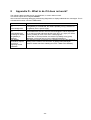
8
Appendix D – What to do if it does not work?
The following table provides tips for error definition, in case it does not work.
This serves a quick error analysis ON SITE.
We recommend activating debugging mode during diagnostics to display additional error messages. This is
activated with monitor command “DEBUGON”.
Error
No controls possible,
no
acknowledgement
No controls possible,
no
acknowledgement,
according to “Status”
the gateway is
detected
The Module
consistently reports
“no STX at
beginning of GW
Feedback”
Proposed solution / error definition
Enter command “Status” in monitor mode.
If the gateway is not detected, the cable is probably wrong / defective or
the gateway has no power supply.
Enter command “List” in monitor mode.
Are all addresses entered? Are here acknowledgment values displayed?
Try to switch several addresses directly with “SET” (e.g. light). If it works,
there is probably an error in the AVIT / AMX program.
Is here also no access possible, the reason is probably wrong group
addresses. (Is the light still on in the neighboring building?)
The Gateway is bein recognized by the module, but during the attempt of
reading out the version, the connection is getting interrupted again.
Solution: Please check teh cabeling from AVIT / AMX to the Gateway.
- 22 -