1
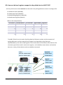
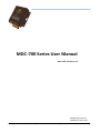
 MDC‐700 Series User Manual Nov. 2015, Version 1.0.2 Written by Liam Lin Edited by Sunny Chiu Copyright © 2014 ICP DAS Co., Ltd. All Rights Reserved. ∗ E‐mail: [email protected] ‐ 1 ‐ Warranty All products manufactured by ICP DAS are warranted against defective materials for a period of one year from the date of delivery to the original purchaser. Warning ICP DAS assumes no liability for damages consequent to the use of this product. ICP DAS reserves the right to change this manual at any time without notice. The information furnished by ICP DAS is believed to be accurate and reliable. However, no responsibility is assumed by ICP DAS for its use, nor for any infringements of patents or other rights of third parties resulting from its use. Copyright Copyright © 2014 by ICP DAS. All rights are reserved. Contact Us If you have any questions, please feel free to contact us via email at: [email protected]
[email protected]
Copyright © 2014 ICP DAS Co., Ltd. All Rights Reserved. ∗ E‐mail: [email protected] ‐ 2 ‐ Contents 1. Introduction ........................................................................................................................................ 4
1.1. Specifications ........................................................................................................................... 7
1.2. Dimensions .............................................................................................................................. 8
1.3. Appearance.............................................................................................................................. 9
2. Configuration .................................................................................................................................... 13
2.1. Assigning an IP address to MDC‐700 ..................................................................................... 14
2.2. Editing the config.csv file ....................................................................................................... 16
2.3. Importing/exporting the config.csv file................................................................................. 21
3.4. Connecting to the Web HMI .................................................................................................. 23
3. Troubleshooting ................................................................................................................................ 26
4. FAQ.................................................................................................................................................... 29
Q1: What are the maximum numbers of polling definition and local register?........................... 29 Q2: What is the maximum number of registers can be accessed in one Modbus command?.... 29 Q3: How are the local registers mapped to the polled data in a MDC‐700?................................ 30 Q4: How to write data to output channels on a Modbus RTU slave device?............................... 32 Q5: How to read the status of each connection? ......................................................................... 33 Revision History .................................................................................................................................... 34
Copyright © 2014 ICP DAS Co., Ltd. All Rights Reserved. ∗ E‐mail: [email protected] ‐ 3 ‐ 1. Introduction The MDC‐700 series module is a Modbus Data Concentrator which can concentrate data from several Modbus RTU slave devices with RS232/RS‐485 interface and allows Modbus TCP masters to read/write data via Ethernet/LAN. The Modbus master can use one Modbus command to get all data on those Modbus RTU slave devices via the MDC‐700 concentrator. In other words, through the help of a MDC‐700 module, the Modbus RTU slave devices can be accessed over Ethernet with better read and write performance. The MDC‐700 series module has the ability to perform up to 240 Modbus RTU commands to read/write data from/to Modbus RTU slave devices and allows up to 8 Modbus TCP masters to get the polled data. The support for Modbus TCP protocol makes the MDC‐700 well integrated into PC‐based applications such as SCADA (Supervisor Control and Data Acquisition) and HMI (Human Machine Interface) programs. Copyright © 2014 ICP DAS Co., Ltd. All Rights Reserved. ∗ E‐mail: [email protected] ‐ 4 ‐ Features Web‐based Interface for Operating and Showing Clear Information By using a regular web browser, users can change the IP address, import/export the configuration file ‐ config.CSV, check the address mapped for polled data and connection status of each polling definition. The MDC firmware will skip the abnormal Modbus polling definition for a while to smoothly perform the whole polling without distribution. Great Capability of Shared Memory The MDC‐700 series module can perform up to 240 polling definitions. And the internal shared memory has four tables to store the polled AI, AO, DI and DO data. Each table can store up to 9600 registers. Copyright © 2014 ICP DAS Co., Ltd. All Rights Reserved. ∗ E‐mail: [email protected] ‐ 5 ‐ Config.CSV to Ease Hard Work of Editing a lot of Definition The Modbus polling definition is defined in a Config.CSV file. Editing/checking a lot of polling definitions is a hard work and it may be making mistakes. A CSV format file can ease the work by using Excel. Furthermore, the built‐in web server allows users to import/export the Config.CSV via a simple mouse‐click action. Support for Modbus TCP Master and Modus RTU Master The MDC‐700 can be accessed by Modbus TCP Master and Modus RTU Master. Changing the mode for a COM port from Master to Slave allows a connected Modus RTU Master to read/write data from/to the Modbus RTU slave devices on the other COM ports. Copyright © 2014 ICP DAS Co., Ltd. All Rights Reserved. ∗ E‐mail: [email protected] ‐ 6 ‐ 1.1. Specifications MDC‐711 MDC‐714 MDC‐741 Ethernet Port x1, 10/100 Base‐TX Protocol Modbus/TCP Slave Max. Connection 8 COM Port RS‐232 x1, (TXD, RXD, RTS, CTS, GND) x4, (TXD, RXD, RTS, CTS, GND) RS‐485 x1, (Data+, Data‐) x1, (Data+, Data‐) Baud Rate 1200, 2400, 4800, 9600, 19200, 38400, 57600, 115200 (bps) Data Format N81, E81, O81 Protocol Modbus RTU Master Max. Node 32 nodes for each RS‐485 port Polling Definition 240 definitions for all RS‐232/485 ports Shared Memory 9600 registers for each of AI, AO, DI and DO Data System x4, (Data+, Data‐) System 5‐Digit 7 Segment LED Display Yes, to display IP address System LED Indicator Yes, to display heartbeat Mechanical Dimension (W x H x D) 102 mm x 125 mm x 28 mm Installation Wall Mount Power Required Supply Voltage +10 VDC ~ +30 VDC (non‐regulated) Power Consumption 2.5 W Environment Operating Temperature
‐25°C ~ +75°C Storage Temperature ‐30°C ~ +80°C Humidity 10 ~ 90% RH, non‐condensing Copyright © 2014 ICP DAS Co., Ltd. All Rights Reserved. ∗ E‐mail: [email protected] ‐ 7 ‐ 1.2. Dimensions Unit: mm Left Side View Front View Top View Bottom View Rear View Copyright © 2014 ICP DAS Co., Ltd. All Rights Reserved. ∗ E‐mail: [email protected] ‐ 8 ‐ 1.3. Appearance Connectors: (For MDC‐714/MDC714) COM3 COM4 COM5 LED Indicator Configuration Display
Ethernet Port Connectors: Power COM2 Reset COM1 LED Indicator The LED is used as a heartbeat indicator and slows to approximately one flash per second. Ethernet Port The MDC‐700 is equipped with a RJ45 port for Ethernet LAN connection. When 100BASE‐TX is operating, the 10/100M LED is lit orange. When 10BASE‐T is operating or the machine is not connected to the network, it is turned off. When an Ethernet link is detected and an Ethernet packet is received, the Link/Act LED is lit green. Copyright © 2014 ICP DAS Co., Ltd. All Rights Reserved. ∗ E‐mail: [email protected] ‐ 9 ‐ Power Connector Configuration Display MDC‐700 includes a 5‐digit 7‐Segment LED display to indicate configuration in a module as below: 11111. 1. 192 2. 168 3. 255 4. 1 22222. 502 001 33333. 1.1152 2.1152 y The IP address for the MDC‐700 (192.168.255.1) y Modbus TCP communication settings Port: 502 Net ID: 1 y Baud rate setting for each COM port COM1: 115200 bps COM2: 115200 bps
44444. 1. 801 2. 801 y Data format setting for each COM port 55555. 00 y The count of TCP/IP connection COM1: 8N1 COM2: 8N1 0: No TCP/IP connection Copyright © 2014 ICP DAS Co., Ltd. All Rights Reserved. ∗ E‐mail: [email protected] ‐ 10 ‐ Reset Shorting the RESET pin to GND pin over 3 seconds can reset the IP/Subnet Mask/Gateway addresses to the factory default settings. RS‐232 Wiring 3‐wire Connection Wiring 5‐wire Connection Wiring Copyright © 2014 ICP DAS Co., Ltd. All Rights Reserved. ∗ E‐mail: [email protected] ‐ 11 ‐ RS‐485 Wiring Copyright © 2014 ICP DAS Co., Ltd. All Rights Reserved. ∗ E‐mail: [email protected] ‐ 12 ‐ 2. Configuration The necessary configuration for Modbus TCP communication, Modbus RTU communication and polling definition is handled by a single file named “config.csv”. Just follow the easy‐to‐use format defined in the config.csv file and import the new config.csv file via a simple mouse‐click on the main page of the MDC‐700, the data on those Modbus RTU slave devices can be accessed over an Ethernet. Only the Function code 01/02/03/04 can be used in the config.csv file: 01: Read Coil Status (Read DO) 02: Read Input Status (Read DI) 03: Read Holding Registers (Read AO) 04: Read Input Registers (Read AI) If you would like to write data to a digital or analog output channel on a Modbus RTU slave device, the output channel needs be mapped with a local register address in the MDC‐700 by editing the polling definition with using corresponding read function code (01 or 03). Refer to Q4 in the 4. FAQ section for more detailed information. The following section will help you to set up your MDC‐700 module, and show you how to use the web interface to obtain configuration and other information related to the MDC module and associated slave devices. Basic operating procedure Step 1: Assign a valid IP address to the MDC‐700. Step 2: Edit the config.csv file. Note that before editing this file, you should confirm the parameter value for any associated Slave devices. Step 3: Upload the config.csv file to the MDC module. Step 4: Verify the status of both the connection and the configuration by browsing the web. Copyright © 2014 ICP DAS Co., Ltd. All Rights Reserved. ∗ E‐mail: [email protected] ‐ 13 ‐ 2.1. Assigning an IP address to MDC‐700 The MDC‐700 is an Ethernet device, which comes with a default IP address of 192.168.255.1; therefore, you must first assign a valid IP address of your network to the module. To access the MDC‐700 by using web‐based interface, you have to know the IP address setting in the module. STEP 1: Connect the PC and MDC‐700 module to an Ethernet Hub/Switch, and power on all the devices. You can also connect a MDC‐700 to PC directly with an Ethernet cable. STEP 2: Set the IP configuration on your computer. If the MDC module is new with using the default IP address of 192.168.255.1, you must chose an IP address for the computer in the range of 192.168.255.2 – 192.168.255.253 that is not already in use. NOTE: Details on how to change the IP address on your computer depend upon the type architecture and operating system you are using. Use the Help and Support functionality on your computer and search for "IP Addressing". STEP 3: Open a web browser and go to the website at http://192.168.255.1, where 192.168.255.1 is the IP address in your MDC module. Copyright © 2014 ICP DAS Co., Ltd. All Rights Reserved. ∗ E‐mail: [email protected] ‐ 14 ‐ STEP 4: Open the IP address configuration interface by clicking on “Ethernet Configuration”. STEP 5: Choose a valid IP address of the network for your MDC module, input the IP/Subnet mask and Gateway addresses and click on the “Apply” button. Make sure that the IP address you pick is not currently in use by another device on the network. NOTE: The IP/Subnet mask/Gateway modified in a MDC‐700 can be reset to factory defaults by shorting the RESET pin to GND pin over 3 seconds. The LED display will show “RESET” as below and the IP address set previously will be cleared and returned to the factory default. Copyright © 2014 ICP DAS Co., Ltd. All Rights Reserved. ∗ E‐mail: [email protected] ‐ 15 ‐ 2.2. Editing the config.csv file The MDC module is configured by a config.csv file to work with your master and RTU slave devices. The Comma Separated Values (CSV) files can be viewed and edited in spreadsheet applications like Microsoft Excel, or in any text editor, in which the comma character (,) typically separates each field of text. In a text editor, it looks like this: The file name “config.csv” can not be changed; it contains four main sections that need to be edited: (1) Modbus Connection, (2) Module information, (3) COM Port Configuration and (4) Polling Definition. Each section starts with a “#” character; follows are names for parameters in this section. A row starting with a “*” character is a set of settings in a section. NOTE: y The name for each parameter can not be changed. y You can make a copy of the config.csv file in three ways and modify it to meet your requirements: 1. Export the config.csv file in your MDC‐700. (See 2.3. Importing/exporting the config.csv file) 2. Make a copy from the company CD:\Napdos\Modbus\MDC700\firmware path. 3. Download the file from http://ftp.icpdas.com/pub/cd/8000cd/napdos/modbus/mdc700/firmware/. What follows are the detailed descriptions: Copyright © 2014 ICP DAS Co., Ltd. All Rights Reserved. ∗ E‐mail: [email protected] ‐ 16 ‐ Modbus Connection The Modbus Connection section is used to configure the Modbus ID of the MDC module and the TCP/IP Port number for Modbus TCP communication. # * TCPPort ModbusID 502 1
TCPPort: Defines the TCP/IP Port number, in the example set to 502. ModbusID: Defines the Modbus ID of the MDC module, in the example set to 1. Module Information The Module Information section is used to record relative information for the MDC module. It will be displayed on the main page of the MDC‐700, and can be used to one MDC module from the others. # * ModuleInfo this is my data concentrator
ModuleInfo: Define the relative information for the MDC module. The string constant has a maximum length of 32 characters. Copyright © 2014 ICP DAS Co., Ltd. All Rights Reserved. ∗ E‐mail: [email protected] ‐ 17 ‐ COM Port Configuration The COM Port Configuration is used to configure the parameters for the RS‐485 Modbus communication connection between the MDC module and the RTU slave devices. # ComPortNo BaudRate DataBit Parity
StopBit
Timeout PollDelay OperatingMode
* 1 115200 8 0
1
100
20 Master
* 2 115200 8 0
1
100
20 Master
* 3 115200 8 0
1
100
20 Master
* 4 115200 8 0
1
100
20 Master
* 5 115200 8 0
1
100
20 Master
The connection configuration for a COM port consists of 8 parameters defined as follows. ComPortNo Specifies the COM port number in MDC module. The COM port number can be 1 or 2 for MDC‐711, and can be 1, 2, 3, 4 or 5 for MDC‐714 and MDC‐741. BaudRate Defines the transmission speed between the MDC module and the RTU slave devices. The BaudRate can be set to 1200/ 2400/ 4800/ 9600/ 19200/ 34800/ 57600/ 115200 (bps) depending on the RTU slave device being used. DataBit Defines the number of data bits in each character. It is fixed to 8 and the RTU slave devices need be set to 8‐bit data, too. Parity Defines the Parity bit. The parity bit can be set to 0 (none), 1 (even) or 2 (odd). StopBit Defines the Stop bits. It is fixed to 1, one stop bit. Timeout Defines the period of time that the MDC module will wait for a response from the RTU slave device. The available range is from 20 to 6000 (ms). PollDelay Defines the Poll Delay between each scan for Modbus RTU communication. The available range is from 5 to 600 (ms). OperatingMode Defines the operating mode. ‐ Master: the com port is used to connect Modbus RTU slave devices. The MDC‐700 is acting as a master to send requests to slave devices. ‐ Slave: the com port is used to connect Modbus RTU master devices. The master devices can read/write data from/to the MDC‐700. Copyright © 2014 ICP DAS Co., Ltd. All Rights Reserved. ∗ E‐mail: [email protected] ‐ 18 ‐ Polling Definition The Polling Definition is used to define Modbus commands to read data from the slave devices. Before attempting to configure the parameters for the Polling Definition, be sure to check the Com port number that the target device is connected to, the Modbus ID setting for the target device, and the function code, start address, and the quantity for reading data. # UseComPort SlaveModbusID FunctionCode RegStartAddr RegCount
* 1 1 1
0
8
* 1 1 2
0
8
* 2 2 1
0
4
* 3 3 2
0
4
* 4 4 3
0
4
* 5 5 4
0
4
Each Polling Definition consists of 6 parameters listed as below: # Defines the type for a polling definition. In the MDC‐700, it provides three types: “*”: Asterisk symbol means that this is a valid polling definition. The MDC‐700 will assign local register for data defined in the definition and save the polled data to the mapping local register. “‐”: Minus sign means that this is a disabled polling definition. The MDC‐700 will assign local register for data defined in the definition but will not poll data. “”: Empty means that this is a null polling definition. The MDC‐700 will neither assign local register for data defined in the definition nor poll data. UseComPort Defines the COM port number to which the slave device is connected. The COM port number can be 1 or 2 for MDC‐711, and can be 1, 2, 3, 4 or 5 for MDC‐714 and MDC‐741. SlaveModbusID Defines the identification of the remote slave. The valid range is from 1 to 255. FunctionCode Defines the request function code. A valid code can be 1 (Read DO), 2 (Read DI), 3 (Read AO) or 4 (Read AI) depending on the I/O features of the slave device. RegStartAddr Defines the starting address, i.e. the address of the first register specified. The available range is from 0 to 9599. RegCount Defines the quantity of registers to be read. The available range is from 1 to 64. NOTE: y The maximum number of all the polling definitions is 240. y The MDC module provides 9600 internal Modbus registers each table (DI/DO/AI/AO) to hold data collected from the RTU slave devices. Copyright © 2014 ICP DAS Co., Ltd. All Rights Reserved. ∗ E‐mail: [email protected] ‐ 19 ‐ y The Modbus ID for the MDC module is defined in Modbus Connection section. y By setting different types for a polling definition to retain register space mapped for specific devices, or to release those space mapped but reserve the definition, the main program on the Modbus master device can be applied in different applications where users would like to change or stop some devices without modification or with minimum level of modification. Copyright © 2014 ICP DAS Co., Ltd. All Rights Reserved. ∗ E‐mail: [email protected] ‐ 20 ‐ 2.3. Importing/exporting the config.csv file Go to the web interface at http://xxx.xxx.xxx.xxx, where xxx.xxx.xxx.xxx is the IP address set in your MDC module. Any standard browser such as Mozilla Firefox, Internet Explorer or Google Chrome can be used to interface the module. NOTE: If you haven’t changed the default IP address in the MDC module, refer to “2.1. Assigning an IP address to MDC‐700” to configure it. Importing a CSV file to MDC STEP 1: Open the Import and Export interface by clicking the Import/Export Configuration button. STEP 2: Choose a CSV file from your computer by clicking the Choose File button. STEP 3: Click on the Import button to import the config.csv file to the MDC. NOTE: After the import process is finished, the MDC module will reboot in 5 seconds. Copyright © 2014 ICP DAS Co., Ltd. All Rights Reserved. ∗ E‐mail: [email protected] ‐ 21 ‐ Exporting a CSV file from MDC STEP 1: Open the Import and Export interface by clicking the Import/Export Configuration button. STEP 2: Click the Export button to export the config.csv file from the MDC module. The config.csv file will be exported to the download directory configured in the web browser. Copyright © 2014 ICP DAS Co., Ltd. All Rights Reserved. ∗ E‐mail: [email protected] ‐ 22 ‐ 3.4. Connecting to the Web HMI Go to the web interface at http://xxx.xxx.xxx.xxx, where xxx.xxx.xxx.xxx is the IP address in your MDC module. Any standard browser such as Mozilla Firefox, Internet Explorer or Google Chrome can be used to interface the MDC. NOTE: The contents of the section may be different depending on the settings contained in the config.csv file. NOTE: The Web HMI requires the Adobe Flash Player to be installed. The latest version of the Adobe Flash Player can be downloaded by accessing the Adobe Systems Incorporated website. The following instructions will help you to install the Adobe Flash Player in your web browser. STEP 1: Go to the Adobe Flash Player Download Center The address for Adobe Flash Player Download Center is http://get.adobe.com/flashplayer/
NOTE: The Adobe Flash Player is subject to change without notice; refer to http://www.adobe.com/support/flashplayer/debug_downloads.html for the latest version of this software. STEP 2: Follow the instructions to download the installation file and install it on your PC. Copyright © 2014 ICP DAS Co., Ltd. All Rights Reserved. ∗ E‐mail: [email protected] ‐ 23 ‐ Introduction to the Web HMI After connecting to the website, the following information will be displayed. # TCPPort * 502 ModbusID 1
# ModuleInfo * this is my data concentrator # ComPortNo BaudRate *
1 115200
*
2 115200
y Module Information The Module Information section of the page provides the module information about the MDC module. y Firmware Information In the Firmware Information section of the page, information about the Firmware Version and the OS Version is displayed y Connection In the Connection section of the page, information about the current connection configuration is displayed, including the TCP Port, Modbus ID of MDC, Baud Rate, Data Bit, Parity, Stop Bit, Timeout, Delay Polls and Operating Mode details. y Polling Definition In the Polling Definition section of the page, information about the current configuration for the Polling Definition is displayed, including the Com Port, SlaveModbusID, Function Code, Starting Address of Register and Count of Register details. Copyright © 2014 ICP DAS Co., Ltd. All Rights Reserved. ∗ E‐mail: [email protected] ‐ 24 ‐ The State of Connection When the state is shown as GOOD, it indicates that the connection was successfully established and the parameter settings are valid. When the state is shown as TIMEOUT, it indicates that the attempted connection has failed. To resolve this issue, check whether the parameters listed below match the settings of the RTU slave device. y Baud Rate y Slave Address y Data Format (Data Bit, Parity and Stop Bit) When the state is shown as ERROR: ILLEGAL FUNCTION, it indicates that the connection was successfully established, but the parameter is invalid. To resolve this issue, check whether the Function Code listed in the Polling Definition match the settings of the Modbus RTU slave device. When the state is shown as ERROR: ILLEGAL DATA VALUE, it indicates that the connection was successfully established, but one or more of the parameters are invalid. To resolve this issue, check whether the Start Address of Register and Count of Register listed in the Polling Definition match the settings of the Modbus RTU slave device. Copyright © 2014 ICP DAS Co., Ltd. All Rights Reserved. ∗ E‐mail: [email protected] ‐ 25 ‐ 3. Troubleshooting
In this chapter, we will explain how to troubleshoot the communication problems. Possible causes of TIMEOUT Situation #1: The slave device is not turned on or the transfer function of the slave site may fail. Solution: Check the slave device is powered up and the communication function is enabled.
Situation #2: The COM port number to which the slave device is connected is not the same with the UseComPort setting in the polling definition. Solution: Connect the slave device to the COM port number that is defined in the polling definition, or fix the UseComPort parameter to the virtual COM port number that the slave device is connected to. Situation #3: The wiring for communication is wrong.
Solution: Exchange the D+ and D‐ wiring of RS‐485 connection, or exchange the Rx and Tx wiring of RS‐232 connection, and check the GND wiring is correct between the slave device and the MDC‐700 module. Situation #4: The Baud Rate or/and Data Format settings in the polling definition are incorrect. Solution: Check and fix the difference of the Baud Rate and Data Format settings between the polling definition and the slave device. ComPortNo BaudRate
DataBit
Parity
StopBit Timeout PollDelay
Operating Mode
1 9600 8 0
1
120
100 Master
2 9600 8 0
1
3000
1000 Master
3 9600 8 0
1
3000
1000 Master
4 9600 8 0
1
120
100 Master
5 9600 8 0
1
120
100 Master
Copyright © 2014 ICP DAS Co., Ltd. All Rights Reserved. ∗ E‐mail: [email protected] ‐ 26 ‐ Situation #5: The ID for the slave device is not correct in the polling definition.
Solution: Check and fix the difference of ID number between the polling definition and the slave device.
Situation #6: The Timeout or PollDelay setting is not long enough. Solution: Lengthen the Timeout or PollDelay setting until it is suitable for communication with the slave device.
ComPortNo BaudRate
DataBit
Parity
StopBit Timeout PollDelay
Operating Mode
1 9600 8 0
1
120
100 Master
2 9600 8 0
1
3000
1000 Master
3 9600 8 0
1
3000
1000 Master
4 9600 8 0
1
120
100 Master
5 9600 8 0
1
120
100 Master
Possible causes of ERROR messages Situation #1: ERROR: ILLEGAL FUNCTION. The FunctionCode used in the polling definition is not an allowable action for the slave. Solution: Correct the FunctionCode parameter. UseComPort SlaveModbusID FunctionCode RegStartAddr RegCount
2 1 3
178
2 2 1 3
124
1 2 2 3
178
2 2 2 3
124
1 2 3 3
178
2 Copyright © 2014 ICP DAS Co., Ltd. All Rights Reserved. ∗ E‐mail: [email protected] ‐ 27 ‐ Situation #2: ERROR: ILLEGAL DATA ADDRESS. The address settings are not allowable addresses for the slave. Solution: Check and fix the RegStartAddr and RegCount settings.
UseComPort SlaveModbusID FunctionCode RegStartAddr RegCount
2 1 3
178
2 2 1 3
124
1 2 2 3
178
2 2 2 3
124
1 2 3 3
178
2 Situation #3: ERROR appeared only. The slave device is abnormal, you have to check the responses from the device. Solution: Step 1: Power cycle the slave device. Step 2: Use third‐party communication software to get the error code responded by the slave device, and follow the instructions in the user manual for the device to solve the problem. Copyright © 2014 ICP DAS Co., Ltd. All Rights Reserved. ∗ E‐mail: [email protected] ‐ 28 ‐ 4. FAQ
Q1: What are the maximum numbers of polling definition and local register?
A1: The maximum number of polling definition in a MDC‐700 is 240, each definition can access up to 64 registers. Each of the four tables (DI/DO/AI/DO) can store up to 9600 registers for polled data. Q2: What is the maximum number of registers can be accessed in one Modbus command from a Modbus master device?
A2: By following the Modbus protocol, the maximum amount of registers that one command can access is 255 of function code 01 and 02, and 126 of function code 03 and 04. Copyright © 2014 ICP DAS Co., Ltd. All Rights Reserved. ∗ E‐mail: [email protected] ‐ 29 ‐ Q3: How are the local registers mapped to the polled data in a MDC‐700? A3: Only the function code 01/02/03/04 can be used in the polling definition section in config.csv file. 01: Read Coil Status (Read DO) 02: Read Input Status (Read DI) 03: Read Holding Registers (Read AO) 04: Read Input Registers (Read AI) Refer to the example below, UseComPort SlaveModbusID FunctionCode RegStartAddr RegCount
1 1 1
0
8 1 1 2
0
8 2 1 1
0
4 2 2 2
0
4 2 3 3
0
4 2 4 4
0
4 The MDC‐700 will sort the order of polling data by COM port number and the sequence of polling definition; and then map the local registers corresponding to the data type (DI/DO/AI/AO) by the order of polling data. So the data comes from different slave devices with the same type will be saved in continuous registers, and a Modbus mater device and read the data on a variety of slave devices with one Modbus command. COM1 Read DO: 00000:00007 Read DI: 10000:10007 Read DO 00000:00007 00008:00011 Read DI 10000:10007 10008:10011 COM2 Read DO: 00000:00003 Read DI: 10000:10003 Read AO 40000:40003 Read AO: 40000:40003 Read AI: 30000:30003 Read AI 30000:30003 Copyright © 2014 ICP DAS Co., Ltd. All Rights Reserved. ∗ E‐mail: [email protected] ‐ 30 ‐ The local registers mapping is listed on the main page of the MDC‐700 module. The MDC‐700 allows users to enable/disable a polling definition by changing the first field of the polling definition section in the config.csv file. There are three types that users can use: “*”: Asterisk symbol means that this is a valid polling definition. The MDC‐700 will assign local register for data defined in the definition and save the polled data to the mapping local register. “‐”: Minus sign means that this is a disabled polling definition. The MDC‐700 will assign local register for data defined in the definition but will not poll the data. “”: Empty means that this is a null polling definition. The MDC‐700 will neither assign local register for data defined in the definition nor poll data. # UseComPort SlaveModbusID FunctionCode RegStartAddr RegCount * 1 1
1
0 8 * 1 1
2
0 8 * 2 2
1
0 4 With the function of retaining register space mapped for specific devices, or releasing those spaces mapped but reserving the definition, the main program on the Modbus master device can be applied in similar applications where users would like to change or stop some devices without modification or with minimum level of modification. Copyright © 2014 ICP DAS Co., Ltd. All Rights Reserved. ∗ E‐mail: [email protected] ‐ 31 ‐ Q4: How to write data to output channels on a Modbus RTU slave device? A4: Step 1: Edit the polling definition for the output channels with read function code in the config.csv file. (For example, use 01 to read DO channels, 03 to read AO channels) UseComPort SlaveModbusID FunctionCode RegStartAddr RegCount
1 1 1
0
8 1 1 2
0
8 2 1 1
0
4 2 2 2
0
4 2 3 3
0
4 2 4 4
0
4 Step 2: Import the config.csv file into the MDC‐700, wait the MDC‐700 reboot in 5 seconds, and then check the addresses for the local registers mapped to the output channels. Step 3: Write data with corresponding function code (05/06/15/16) on your Modbus master device to the local registers mapped for the output channels, the MDC‐700 will process writing operations to the slave devices. Copyright © 2014 ICP DAS Co., Ltd. All Rights Reserved. ∗ E‐mail: [email protected] ‐ 32 ‐ Q5: How to read the status of each connection?
A5: The status for each connection is saved in the sequence of polling definition from local register address 39600. The maximum number of polling definition in the config.csv file is 240, so the available address for the connection status is from 39600 to 39839. A Modbus master use function code 04 to read the status, up to 126 register of status can be read in one command.
For example, the status of the graph shown above is presented as the third column in the following table. Def. number Address Status Status display on web page Def.#001 39600 0 GOOD Def.#002 39601 0 GOOD Def.#003 39602 0xFFFF TIMEOUT Def.#004 39603 0x8201 ERROR: ILLEGAL FUNCTION Def.#005 39604 0 GOOD Def.#006 39605 0x8402 ERROR: ILLEGAL DATA ADDRESS The value of status: 0: Good 0xFFFF: Timeout 0x8XYY: Exception Rresponse. X ‐ Modbus Function Code. YY ‐ Exception Code. Exception Name Code Meaning 01 Illegal Function The function code received is not an allowable action.
02 Illegal Data Address The data address received in the query is not an allowable address.
03 Illegal Data Value A value contained in the query data field is not an allowable value. 04 Illegal response length The request would generate a response with size bigger than that available for MODBUS protocol.
Copyright © 2014 ICP DAS Co., Ltd. All Rights Reserved. ∗ E‐mail: [email protected] ‐ 33 ‐ Revision History Revision Date Description 1.0.0 2014/11 First released 1.0.1 2015/07 Added description for MDC‐741. 1.0.1 2015/11 Added dimensions, appearance information and Troubleshooting, FAQ sections. Copyright © 2014 ICP DAS Co., Ltd. All Rights Reserved. ∗ E‐mail: [email protected] ‐ 34 ‐