1
Instruction Manual
NXB-KNX
KNX Communications Gateway
NetLinx Interface Controllers
L a s t R e v is e d : 4 / 2 8 / 2 0 1 4
AMX Limited Warranty and Disclaimer
This Limited Warranty and Disclaimer extends only to products purchased directly from AMX or an AMX Authorized Partner which
include AMX Dealers, Distributors, VIP’s or other AMX authorized entity.
AMX warrants its products to be free of defects in material and workmanship under normal use for three (3) years from the date of
purchase, with the following exceptions:
•
Electroluminescent and LCD Control Panels are warranted for three (3) years, except for the display and touch overlay components are warranted for a period of one (1) year.
•
Disk drive mechanisms, pan/tilt heads, power supplies, and MX Series products are warranted for a period of one (1) year.
•
AMX lighting products are guaranteed to switch on and off any load that is properly connected to our lighting products, as long
as the AMX lighting products are under warranty. AMX also guarantees the control of dimmable loads that are properly connected to our lighting products. The dimming performance or quality there of is not guaranteed, impart due to the random combinations of dimmers, lamps and ballasts or transformers.
•
AMX software is warranted for a period of ninety (90) days.
•
Batteries and incandescent lamps are not covered under the warranty.
•
AMX AutoPatch Epica, Modula, Modula Series4, Modula CatPro Series and 8Y-3000 product models will be free of defects in
materials and manufacture at the time of sale and will remain in good working order for a period of three (3) years following the
date of the original sales invoice from AMX. The three-year warranty period will be extended to the life of the product (Limited
Lifetime Warranty) if the warranty card is filled out by the dealer and/or end user and returned to AMX so that AMX receives it
within thirty (30) days of the installation of equipment but no later than six (6) months from original AMX sales invoice date. The
life of the product extends until five (5) years after AMX ceases manufacturing the product model. The Limited Lifetime Warranty
applies to products in their original installation only. If a product is moved to a different installation, the Limited Lifetime Warranty
will no longer apply, and the product warranty will instead be the three (3) year Limited Warranty.
All products returned to AMX require a Return Material Authorization (RMA) number. The RMA number is obtained from the AMX
RMA Department. The RMA number must be clearly marked on the outside of each box. The RMA is valid for a 30-day period. After
the 30-day period the RMA will be cancelled. Any shipments received not consistent with the RMA, or after the RMA is cancelled, will
be refused. AMX is not responsible for products returned without a valid RMA number.
AMX is not liable for any damages caused by its products or for the failure of its products to perform. This includes any lost profits, lost
savings, incidental damages, or consequential damages. AMX is not liable for any claim made by a third party or by an AMX Authorized Partner for a third party.
This Limited Warranty does not apply to (a) any AMX product that has been modified, altered or repaired by an unauthorized agent or
improperly transported, stored, installed, used, or maintained; (b) damage caused by acts of nature, including flood, erosion, or earthquake; (c) damage caused by a sustained low or high voltage situation or by a low or high voltage disturbance, including brownouts,
sags, spikes, or power outages; or (d) damage caused by war, vandalism, theft, depletion, or obsolescence.
This limitation of liability applies whether damages are sought, or a claim is made, under this warranty or as a tort claim (including
negligence and strict product liability), a contract claim, or any other claim. This limitation of liability cannot be waived or amended by
any person. This limitation of liability will be effective even if AMX or an authorized representative of AMX has been advised of the
possibility of any such damages. This limitation of liability, however, will not apply to claims for personal injury.
Some states do not allow a limitation of how long an implied warranty last. Some states do not allow the limitation or exclusion of incidental or consequential damages for consumer products. In such states, the limitation or exclusion of the Limited Warranty may not
apply. This Limited Warranty gives the owner specific legal rights. The owner may also have other rights that vary from state to state.
The owner is advised to consult applicable state laws for full determination of rights.
EXCEPT AS EXPRESSLY SET FORTH IN THIS WARRANTY, AMX MAKES NO OTHER WARRANTIES, EXPRESSED OR
IMPLIED, INCLUDING ANY IMPLIED WARRANTIES OF MERCHANTABILITY OR FITNESS FOR A PARTICULAR PURPOSE. AMX
EXPRESSLY DISCLAIMS ALL WARRANTIES NOT STATED IN THIS LIMITED WARRANTY. ANY IMPLIED WARRANTIES THAT
MAY BE IMPOSED BY LAW ARE LIMITED TO THE TERMS OF THIS LIMITED WARRANTY. EXCEPT AS OTHERWISE LIMITED
BY APPLICABLE LAW, AMX RESERVES THE RIGHT TO MODIFY OR DISCONTINUE DESIGNS, SPECIFICATIONS, WARRANTIES, PRICES, AND POLICIES WITHOUT NOTICE.
Table of Contents
Table of Contents
NXB-KNX KNX Communications Gateway .........................................................1
Overview .................................................................................................................. 1
Product Specifications ............................................................................................. 1
Installation ..........................................................................................................3
Wiring and Connections............................................................................................ 3
Ethernet 10/100 Base-T RJ-45 Wiring Configuration ................................................ 3
PoE (Power Over Ethernet) ............................................................................................. 4
KNX Connector......................................................................................................... 4
Configuration ......................................................................................................5
Overview .................................................................................................................. 5
Determining the IP Address of the NXB-KNX........................................................... 5
NetLinx Studio (featuring Zero-Config functionality)....................................................... 5
Accessing the NXB-KNX WebConsole via Zero-Config ................................................... 6
Accessing the WebConsole via Web Browser ................................................................. 6
Admin Menu ............................................................................................................. 7
Device Configuration ................................................................................................ 7
Device Configuration tab ................................................................................................ 7
Changing the Device Number ......................................................................................... 7
Master Connection tab.................................................................................................... 8
Security Settings ....................................................................................................... 8
Enable / Disable Security Settings .................................................................................. 9
Login Information ............................................................................................................ 9
Logging Into the Configuration Manager (With Security Enabled).................................. 9
IP Settings............................................................................................................... 10
Port Settings ........................................................................................................... 10
Clock Manager........................................................................................................ 11
Clock Manager - Mode Manager ................................................................................... 12
Clock Manager - Daylight Savings ................................................................................. 13
Clock Manager - NIST Servers ....................................................................................... 13
NetLinx Programming ......................................................................................15
Overview ................................................................................................................ 15
Understanding the KNX Bus ................................................................................... 15
KNX Bus Diagram.......................................................................................................... 16
Notes on Line Couplers ................................................................................................. 16
User Data (DPT) Specifications and Requirements ........................................................ 17
Integrating with NetLinx......................................................................................... 18
Channels and Levels ...................................................................................................... 18
NXB-KNX KNX Communications Gateway
i
Table of Contents
Data Types ................................................................................................................... 18
Feedback ................................................................................................................ 19
Runtime ......................................................................................................................... 19
Debugging .................................................................................................................... 19
AMX_NXB_MOD Module........................................................................................ 20
AMX_KNX_Updater Module ................................................................................... 20
Accessing Actuators On the KNX Bus..................................................................... 20
KNX_Table.axi Include File ............................................................................................ 20
KNX_Tools.axi Include File ............................................................................................ 20
Analyzing Feedback ................................................................................................ 21
NetLinx SEND_COMMANDs................................................................................... 21
ADD= .....................................................................................................................................
ADR........................................................................................................................................
BIND= ....................................................................................................................................
DATE=....................................................................................................................................
DATE? ....................................................................................................................................
DEBUGON..............................................................................................................................
DEBUGON= ...........................................................................................................................
DEBUGOFF ............................................................................................................................
DEL.........................................................................................................................................
EIS5=......................................................................................................................................
EIS5? ......................................................................................................................................
ERRORM= ..............................................................................................................................
GET= ......................................................................................................................................
GET?.......................................................................................................................................
HELP (or) /? ............................................................................................................................
ICSP........................................................................................................................................
LIST ........................................................................................................................................
LIST <No> ..............................................................................................................................
LIST <No> <No2> ..................................................................................................................
LIST <Type> ...........................................................................................................................
LIST BIND ...............................................................................................................................
LIST FLAGS.............................................................................................................................
LIST GAPS ..............................................................................................................................
LIST LOAD..............................................................................................................................
LIST POLL ...............................................................................................................................
LIST SAVE...............................................................................................................................
LIST SUM................................................................................................................................
LIST WATCH...........................................................................................................................
POLL= ....................................................................................................................................
POLL?.....................................................................................................................................
POLLDELAY= .........................................................................................................................
POLLSTART ............................................................................................................................
SEARCH..................................................................................................................................
SENDDELAY= ........................................................................................................................
SET=.......................................................................................................................................
STATE? ...................................................................................................................................
STATUS ..................................................................................................................................
TIME=.....................................................................................................................................
TIME? .....................................................................................................................................
ii
21
21
22
22
22
22
22
23
23
23
23
23
24
24
24
24
24
24
25
25
25
25
25
26
26
26
26
26
26
26
27
27
27
27
28
28
28
28
29
NXB-KNX KNX Communications Gateway
Table of Contents
VAL= ......................................................................................................................................
VERSION ................................................................................................................................
WATCH ..................................................................................................................................
WATCH OFF...........................................................................................................................
WHEN= ..................................................................................................................................
29
29
29
29
29
Sample Program ..................................................................................................... 30
KNX Table ..................................................................................................................... 30
Notes For Programming................................................................................................ 30
Example 1 - Structure of KNX Table With Functions From KNX_Tools.axi.................... 30
Example 2 - Structure of KNX-Table with SEND_COMMANDS..................................... 32
Example 3 - Load Configuration from File..................................................................... 33
Example 4 - Main Program ............................................................................................ 34
KNX_Tools.axi......................................................................................................... 35
Functions Available In KNX_Tools.axi............................................................................ 35
KNXSet ..................................................................................................................................
KNXGet..................................................................................................................................
KNXPoll..................................................................................................................................
KNXAdd .................................................................................................................................
KNXWhenPoll.........................................................................................................................
KNXString2Array ...................................................................................................................
KNXArray2String ...................................................................................................................
35
35
35
35
35
35
35
Cross-Line Communication ...............................................................................37
Overview ................................................................................................................ 37
Integrating the NXB-KNX Virtual Device Into An ETS3 Project..................................... 37
Adding the Virtual Device to the ETS3 Project ............................................................. 38
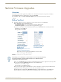
NetLinx Firmware Upgrades .............................................................................41
Overview ................................................................................................................ 41
Before You Start ..................................................................................................... 41
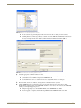
Sending a Firmware (*.KIT) File To the NXB-KNX ......................................................... 42
Additional Documentation ............................................................................................ 44
One-Time Upgrade of the NXB-KNX to a Native NetLinx Device ....................45
Overview ................................................................................................................ 45
Determining the Current Firmware Version Of the NXB-KNX....................................... 46
Browse For the New Firmware Upload File................................................................... 46
If Current Firmware Version Is Lower Than v1.0.36....................................................... 46
Determining the Current Application Version Of the NXB-KNX ................................... 47
If Current Application Version Is Lower Than v2.0.15 ................................................... 47
Appendix A: Telnet Commands ........................................................................49
Overview ................................................................................................................ 49
Establishing a Terminal Connection Via Telnet ....................................................... 49
Terminal Commands ............................................................................................... 50
NXB-KNX KNX Communications Gateway
iii
Table of Contents
Appendix B: Troubleshooting ...........................................................................55
Overview ................................................................................................................ 55
iv
NXB-KNX KNX Communications Gateway
NXB-KNX KNX Communications Gateway
NXB-KNX KNX Communications Gateway
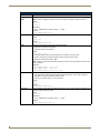
Overview
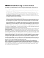
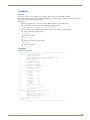
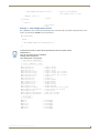
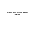
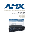
The NXB-KNX KNX Communications Gateway (FG2031-01) allows AMX NetLinx Integrated Controllers the ability
to control, integrate and communicate with homes and buildings that utilize the KNX communication protocol.
KNX is the world’s first open, royalty-free, and platform independent standard for home and commercial building
control.
(front)
(rear)
FIG. 1 NXB-KNX Interface
Product Specifications
NXB-KNX Specifications
Front Panel LEDs
• Status (green): Blinks to indicate that the unit is communicating with the NetLinx Master. Any
state other than blinking indicates the unit has not completed boot up.
• KNX (green): Solid on indicates power is on and the unit is connected to the KNX bus.
• Output (red): Lights to indicate traffic from the NXB-KNX to the KNX bus.
• Input (yellow): Lights to indicate traffic from the KNX bus to the NXB-KNX.
Rear Panel Connectors: • KNX 2-pin captive-wire connector (optically isolated).
• Ethernet Port - 10/100 Ethernet with PoE. LEDs show communication activity, connection
status, speeds, and mode information:
SPD (speed) - Yellow LED lights On when the connection speed is 100 Mbps and turns Off
when the speed is 10 Mbps.
L/A (link/activity) - Green LED lights On when the Ethernet cables are connected and
terminated correctly, and blinks when receiving Ethernet data packets.
Power Requirements:
• PoE powered – no local Power Supply needed
• IEEE 802.3af Compliant
Memory:
• 64 Mbytes of RAM
• 256 Mbytes of FLASH
Dimensions (HWD):
With feet:
• 1.66" x 5.54" x 4.10"
• 4.216 cm x 14.07 cm x 10.42 cm
Without feet:
• 1.52" x 5.54" x 4.10"
• 3.861 cm x 14.07 cm x 10.42 cm
Weight:
NXB-KNX KNX Communications Gateway
1.45 lbs. (0.65 kg)
1
NXB-KNX KNX Communications Gateway
NXB-KNX Specifications (Cont.)
Operating Environment: • Operating Temperature: 32°F - 104°F (0°C - 40°C)
• Relative Humidity: 5% to 85% non-condensing
• Intended for indoor use only
Included Accessories:
• Rubber feet
• Green 2-Pin 5mm Phoenix connector with captive screws
Other AMX Equipment:
• AC-DIN-CS3 DIN Rail Mounting Bracket (FG532-01)
• PS-POE-AF PoE Injector (FG423-80)
Certifications:
• FCC Class B
• CE
• IEC60950
• RoHS
2
NXB-KNX KNX Communications Gateway
Installation
Installation
Wiring and Connections
To avoid any damage to the electronic component, installation must be performed in
an ESD safe environment.
Do not connect power to the NXB-KNX until the wiring is complete.
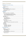
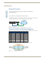
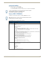
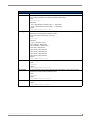
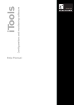
The NXB-KNX is installed between the NetLinx Master and the KNX control bus, and passes NetLinx control
commands to the KNX control bus via 2-wire twisted pair cabling, as indicated in FIG. 2:
NetLinx Master
KNX
Control
Bus
NXB-KNX
PoE injector
Ethernet 10/100
2-wire twisted pair
FIG. 2 NXB-KNX installation
After you have completed the installation, consult the Configuration section on page 5.
Ethernet 10/100 Base-T RJ-45 Wiring Configuration
The table below describes the pinouts, signals, and pairing for the Ethernet 10/100 Base-T connector and cable.
Ethernet Pinouts and Signals
Pin
Signals
Connections
Pairing
1 --------- 2
1
TX +
1 --------- 1
2
TX -
2 --------- 2
Color
White-Orange
Orange
3
RX +
3 --------- 3
4
no connection
4 --------- 4
3 --------- 6
Blue
White-Green
5
no connection
5 --------- 5
White-Blue
6
RX -
6 --------- 6
Green
7
no connection
7 --------- 7
White-Brown
8
no connection
8 --------- 8
Brown
FIG. 3 diagrams the RJ-45 pinouts and signals for the Ethernet RJ-45 connector and cable.
FIG. 3 Straight-Through Wiring
NXB-KNX KNX Communications Gateway
3
Installation
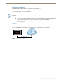
PoE (Power Over Ethernet)
The NXB-KNX uses CAT5/CAT6 wire via the Ethernet port for PoE power.
Use the PS-POE-AF Power over Ethernet Injector (FG423-80) to simplify wiring and installation by eliminating the
need for an AC outlet at each point of installation.
The NXB-KNX can be placed up to approximately 330’ (100 meters) from PoE
Injector.
If used with a non PoE-capable Ethernet switch (such as the NXA-ENET24), then an optional PS-POE-AF
Power-over-Ethernet (PoE) power supply is required to provide power to the NXB-KNX.
If the NXB-KNX is used with a PoE-capable Ethernet switch (such as the NXA-ENET24PoE), then no PoE
Injectors are required.
KNX Connector
The KNX connector on the rear panel is a 2-pin captive-wire connector (optically isolated) that provides communication
between the NXB-KNX and the KNX control system via 2-wire shielded twisted pair cabling (FIG. 4).
-
KNX
Control
Bus
+
2-wire twisted pair
FIG. 4 KNX Connector wiring diagram
4
NXB-KNX KNX Communications Gateway
Configuration
Configuration
Overview
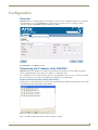
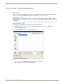
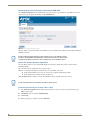
NXB-KNX units have a built-in WebConsole that allows you to make various configuration settings via a web browser
on any PC that has access to the NXB-KNX device. The web console consists of a series of web pages that are
collectively called the "NXB-KNX Configuration Manager" (FIG. 5).
Click here to log in
Hover mouse here to access
the Admin drop-down menu
FIG. 5 NXB-KNX Configuration Manager - IP Settings Page (initial view)
The NXB-KNX is set to DHCP by default.
Determining the IP Address of the NXB-KNX
NXB-KNX units feature a built-in zero-configuration networking client that allows you to determine the unit’s IP
address via NetLinx Studio v3.0 (or higher), or a similar zero-configuration client.
Zero-configuration (or Zero-Config) technology provides a general method to discover services on a local area network.
In essence, it allows you to set up a network without any configuration, as described below.
NetLinx Studio (featuring Zero-Config functionality)
NetLinx Studio (v3.0 or higher) features a "Zero-Config" tab in the Workspace Window. This tab provides Zero-Config
networking functionality within NetLinx Studio (FIG. 6).
FIG. 6 Workspace Bar - Zero-Config tab
Refer to the NetLinx Studio online help for details on using Zero-Config.
NXB-KNX KNX Communications Gateway
5
Configuration
Accessing the NXB-KNX WebConsole via Zero-Config
Assuming that the NXB-KNX resides on the same LAN as the PC running NetLinx Studio, and the NetLinx Master to
which the NXB-KNX is connected, you can access the NXB-KNX via the Zero-Config feature in Netlinx Studio, as
described below:
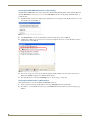
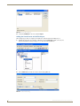
1. In NetLinx Studio (version 3.0 or higher), right-click inside the Zero-Config tab of the Workspace Bar to access the
Zero-Config context menu (FIG. 7).
FIG. 7 NetLinx Studio - Zero-Config context menu
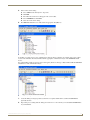
2. Select Refresh List to generate an initial listing of all Zero-Config devices detected (FIG. 8).
3. Click the plus symbol (+) to expand any device in the Zero-Config list. The device’s current IP Address is listed
below the device name (FIG. 8):
FIG. 8 Workspace Bar - Zero-Config tab
4. You can access any device in the Zero-Config list simply by double-clicking on it's entry. The selected device's
WebConsole (HTML) is displayed in a NetLinx Studio window.
5. The unit’s IP Address can be edited IP Settings page (see the IP Settings on page 10).
Accessing the WebConsole via Web Browser
From any PC that has access to the LAN that the NXB-KNX resides on:
1. Open a web browser and type the IP Address of the target NXB-KNX unit in the Address Bar.
2. Press Enter to access the WebConsole for the specified NXB-KNX unit. The initial view is the IP Settings page
(FIG. 5).
6
NXB-KNX KNX Communications Gateway
Configuration
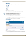
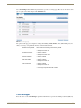
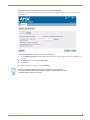
Admin Menu
There are several configuration pages included in the Configuration Manager, all of which are accessed via the Admin
drop-down menu (FIG. 9):
FIG. 9 NXB-KNX Configuration Manager -Admin menu
Click on an option in this menu to access each of the configuration pages, as described in the following
sub-sections:
If you see the additional entries: Application Upgrade and Firmware Upgrade in
the Admin menu, it is an indication that your NXB-KNX is currently using an older
version of the device Application and Firmware.
Refer to the One-Time Upgrade of the NXB-KNX to a Native NetLinx Device on
page 45 for instructions on upgrading your NXB-KNX to the latest NetLinx Firmware.
Once the unit has been upgraded to the current version of NetLinx Firmware, the
Admin Menu will appear as it is shown in FIG. 9.
Device Configuration
Select Device Configuration from the Admin menu to open the Device Configuration page. Use the options on the page
to specify a Device Number and define connection information for the NetLinx Master.
This page contains two tabs: Device Configuration, and Master Connection.
Device Configuration tab
The initial view of this page is the Device Configuration tab (FIG. 10):
The currently installed application
version is displayed here
FIG. 10 Device Configuration page - Device Configuration tab
The current device number assigned to this NXB-KNX unit is displayed in the Device Number field.
The version of the device Application currently loaded on this unit is displayed under Current Application Information.
Changing the Device Number
NXB-KNX KNX Communications Gateway
7
Configuration
1. Enter a Device Number for this NXB-KNX unit in the Device Number text field.
2. Click Accept to save your changes.
3. Press Reboot to reboot the NXB-KNX and apply the new Device Number assignment.
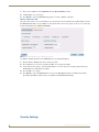
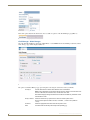
Master Connection tab
The options in the Master Connection tab allow you to view and edit connection details for the NetLinx Master to which
this NXB-KNX unit will be connected (FIG. 11). Note that the Master Connection options can also be accessed directly
from the Admin Menu (select Master Connection).
FIG. 11 Device Configuration page - Master Connection tab
To establish communication between the NXB-KNX and a specific NetLinx Master:
1. Enter the Master’s IP/URL in the Master IP/URL text field.
2. The default Master Port Number assignment is 1319 - do not change this number.
3. Under Authentication Settings, enter the NetLinx Master’s Username and Password (only required if the target
NetLinx Master has Authentication enabled).
4. Press Accept to save changes.
5. Press Reboot to reboot the NXB-KNX. Once rebooted, the NXB-KNX should be in communication with the
Specified NetLinx Master (indicated by a steady blink on the NXB-KNX Status LED).
Security Settings
8
NXB-KNX KNX Communications Gateway
Configuration
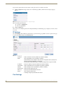
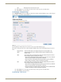
Select Security Settings from the Admin menu to open the Security Settings page (FIG. 12). Use the options on the page
to specify security options and login information for this NXB-KNX unit.
FIG. 12 Security Settings page
Enable / Disable Security Settings
Web Security:
Click this checkbox to enable Web Security.
When Web security is enabled, a username and password are required to access any
system Web pages.
Default = disabled
Telnet Security:
Click this checkbox to enable Telnet Security.
With Telnet Security enabled, a username and password are required to establish a
Telnet or SSH connection.
Default = disabled
Admin Security:
Click this checkbox to enable Admin Security.
With Admin Security enabled, a username and password are required to modify any
system configuration item.
Default = disabled
Restore Factory
Defaults:
Click to restore all security settings to their factory defaults.
Default = all disabled
Login Information
Use this set of options to specify a Username and Password. These will be required only if one or more of the Security
Settings are enabled.
Username:
Enter the Username that will be required to login to this unit if security is enabled. The
default Username is "administrator".
New Password:
Enter a new password that will be required to login to this unit if security is enabled.
The default Password is "password".
Confirm Password:
Re-enter the new password in this field.
Restore Factory
Defaults:
Click to restore the login information to the factory defaults:
• Default Username = administrator
• Default Password = password
Click Accept to save your changes. Note that changes on this page take effect immediately.
Click Cancel to cancel any changes.
Logging Into the Configuration Manager (With Security Enabled)
NXB-KNX KNX Communications Gateway
9
Configuration
Login is only required if the Web and/or Admin security options have been enabled on the unit.
1. Click the Login link in the upper-right corner of the initial page (FIG. 5). This invokes the Login popup page
(FIG. 13).
FIG. 13 NXB-KNX Configuration Manager - Login popup page
Enter the default login information:
Username = administrator
Password = password
2. Click the Login button.
Once you have successfully logged into the Configuration Manager, the IP Settings page is displayed, and can be edited
as needed.
IP Settings
Select IP Settings from the Admin drop-down menu to open the IP Settings page (FIG. 14). Use the options on the page
to specify network/IP settings for this NXB-KNX unit.
FIG. 14 IP Settings page
Hostname:
DHCP:
Enter a Hostname for this unit (enabled only if DHCP is disabled).
Click to toggle DHCP on this unit (default = enabled).
Note that DHCP must be enabled in order for the zero-configuration client (i.e. Bonjour for
Windows) to detect the NXB-KNX on the network.
See the NetLinx Studio (featuring Zero-Config functionality) section on page 5 for details.
IP Address:
Enter an IP Address for this unit (enabled only if DHCP is disabled).
Subnet Mask:
Enter a Subnet Mask for this unit (enabled only if DHCP is disabled).
Gateway:
Enter a Gateway for this unit (enabled only if DHCP is disabled).
Domain Suffix:
Enter the Domain Suffix for this unit.
DNS 1, 2, 3:
Enter up to three DNS addresses for this unit.
Reboot:
Click to initiate a system reboot.
IP Settings changes only take effect after a reboot.
Port Settings
10
NXB-KNX KNX Communications Gateway
Configuration
Select Port Settings from the Admin drop-down menu to open the Port Settings page (FIG. 15). Use the options on the
page to specify various Port settings for this NXB-KNX unit.
FIG. 15 Port Settings page
The options on this page provide inputs for enabling and disabling of HTTP, HTTPS, Telnet, SSH and FTP ports, and
allow you to change each port number from its standard default assignment.
Restore Factory Defaults:
HTTP Port Number:
Click to restore all Port settings to the factory defaults.
• Default = enabled
• Default port number = 80
HTTPS Port Number:
• Default = enabled
• Default port number = 443
Telnet Port Number:
• Default = enabled
SSH Port Number:
• Default = enabled
• Default port number = 23
• Default port number = 22
FTP Port Number:
• Default = enabled
• Default port number = 21
Reboot:
• Click to initiate a system reboot.
• Port changes only take effect after a reboot.
Clock Manager
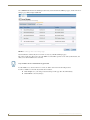
Hover the cursor over the Clock Manager option in the Admin menu to open the Clock Manager sub-menu (FIG. 16).
NXB-KNX KNX Communications Gateway
11
Configuration
FIG. 16 Clock Manager sub-menu
Each of the options listed in the sub-menu are also accessible via options on the Clock Manager page (FIG. 17).
FIG. 17 Clock Manager options
Clock Manager - Mode Manager
Select the main Clock Manager entry in the Admin Menu, or select Mode from the Clock Manager sub-menu, and the
Mode Manager page will be displayed (FIG. 18):
FIG. 18 Clock Manager - Mode Manager page
The options on the Mode Manager page provide inputs for selecting the current mode of the system time:
Time Sync:
Use the radio buttons to select either Network Time or StandAlone.
Note: If using StandAlone mode, the time will be valid only until the unit is rebooted. Once
the unit is rebooted, the time will be lost, and will have to be reset.
Note that the Daylight Savings and NIST Servers tabs are enabled only if Network Time is
selected as the mode.
Re Sync Period:
Select the desired re-sync period for the clock from this drop-down menu.
Re-sync period options include 5 minutes, 15 minutes, 1, 2 and 4 hours (default =
1 hour).
12
Timezone:
Select the appropriate Time Zone from the drop-down menu.
Date:
Use these fields to manually enter today’s date (mm/dd/yyyy).
NXB-KNX KNX Communications Gateway
Configuration
Time:
Manually enter the current time (hh:mm:ss).
Click Accept to save your changes. Note that changes on this page take effect immediately.
Click Cancel to cancel any changes.
Clock Manager - Daylight Savings
Select Daylight Savings from the Clock Manager sub-menu (or from the main Clock Manager page), and the Daylight
Savings Manager page will be displayed (FIG. 19):
FIG. 19 Clock Manager - Daylight Savings Manager page
Note that this tab is enabled only if Network Time is selected (on the Mode Manager page).
The options on this page allow you to enable and disable daylight savings, and specify daylight savings start and end
times.
Daylight Savings:
Use these radio buttons to turn daylight savings time on and off (default = Off).
Offset:
Use these drop-down menus to specify the amount of time to offset the clock for
daylight savings.
Starts:
These options allow you to specify when to start using daylight savings time. Select a
month and time to start from the drop-down menus.
• Select Fixed to start daylight savings at a specific Day, Month and Time (an additional
field for Day is provided when this radio button is selected).
• Select Occurrence to start daylight savings at a specified occurrence (additional
fields for Week of the Month, and Day of the Week are provided).
Ends:
These options allow you to specify when to stop using daylight savings time. Select a
month and time to start from the drop-down menus.
• Select Fixed to end daylight savings at a specific Day, Month and Time (an additional
field for Day is provided when this radio button is selected).
• Select Occurrence to end daylight savings at a specified occurrence (additional fields
for Week of the Month, and Day of the Week are provided).
Click Accept to save your changes. Note that changes on this page take effect immediately.
Click Cancel to cancel any changes.
Clock Manager - NIST Servers
NXB-KNX KNX Communications Gateway
13
Configuration
Select NIST Servers from the Clock Manager sub-menu (or from the main Clock Manager page), and the NIST Server
Manager page will be displayed (FIG. 20):
FIG. 20 Clock Manager - NIST Server Manager page
Note that this tab is enabled only if Network Time is selected (on the Mode Manager page).
The options on this page allow you to select the NIST server that will be queried at each clock synchronization, and
allow you to add more NIST servers to the list.
Only one NIST server is selectable at any given time.
To add a NIST server, enter the NIST Server Name, IP Address and Location in the fields provided.
To remove a NIST server from the list, click the Remove button.
Click Accept to save your changes. Note that changes on this page take effect immediately.
Click Cancel to cancel any changes.
14
NXB-KNX KNX Communications Gateway
NetLinx Programming
NetLinx Programming
Overview
It is important to understand that the NXB-KNX cannot configure a KNX system. The NXB-KNX serves a functioning
KNX system, and can only access bus elements with permitted use.
For a successful connection to a KNX system, expert KNX knowledge and access to
a knowledgeable KNX installer is crucial.
A wrongly set reading flag in an actuator or restrictively programmed line coupler are
difficult to find without the right analysis tools.
Understanding the KNX Bus
KNX is a bus system: all components are connected to the same line and share the available bandwidth. The KNX bus is
a 2-core wire, providing 24V power as well as data transfer between devices.
In contrast to AMX, the KNX system is organized peripherally - there is no "Master" or "Central Controller" controlling
communication. Rather, every device may transmit data to any other device. The KNX protocol ensures that only one
device transmits at a time, to avoid collisions as much as possible.
All communication is carried out via "Telegrams". A Telegram is a data package consisting of the following components:
Source ID - hardware address of the transmitting device
Destination Address - group addresses of receiving devices
User data
A Telegram can be transmitted to several Destination Addresses simultaneously (for instance to switch off all lights in a
room at the same time). There is a basic difference between Source IDs and Destination Addresses:
A Source ID is the hardware address of the device transmitting the Telegram.
A Destination Address is a group address characterizing a function.
Thus each device connected to KNX has exactly one Source ID, but may have several Destination Addresses.
Furthermore, it is common for several Source IDs (devices) to respond to the same Destination Address.
The KNX installer assigns both address types - the Source IDs describing the type and number of utilized devices
(assigned during planning and installation).
Hardware addresses are irrelevant to the NXB-KNX. Destination Addresses are important for AMX programmers, since
they define the functions a KNX installation can perform. Functions are actuated by transmitting a certain value to a
Destination Address.
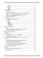
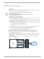
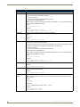
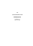
The diagram in FIG. 21 gives a graphic overview to the course of communication from the project-oriented Netlinx
source code to the NXB-KNX.
NetLinx Master
NXB-KNX
AMX NXB
MOD
KNX
Control
Bus
NetLinx
Program
AMX NXB
Updater
FIG. 21 Course of communication
NXB-KNX KNX Communications Gateway
15
NetLinx Programming
KNX Bus Diagram
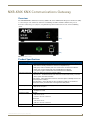
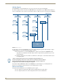
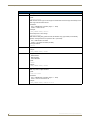
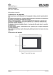
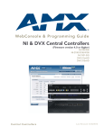
The NXB-KNX is a transparent KNX device and can be connected at any location with the KNX.
In contrast to simple actuators and sensors, the NXB-KNX may be responsible for up to 3,000 Destination Addresses
(where a normal dimmer only responds to four Destination Addresses). FIG. 22 provides a basic diagram of a KNX Bus:
KNX Backbone
Line Coupler
Actuator
Line Coupler
Actuator
Line Coupler
Line Coupler
Actuator
NXB-KNX
Actuator
Actuator
Sensor
Sensor
Sensor
Sensor
KNX Line
KNX Line
Sensor
KNX Line
KNX Line
NXB-KNX
AMX
FIG. 22 KNX Bus Diagram
It is important to ensure that the NXB-KNX can respond to all bus Telegrams in question. When using line couplers,
careful planning is necessary. The following should be considered:
Bus Telegrams have to reach the NXB-KNX. If line couplers are inserted between NXB-KNX and the
component to be controlled, then the filter tables of the line couplers must be programmed to pass on all
relevant Telegrams.
Older line couplers may be slow. In this case, KNX devices will require a certain amount of time between
receiving Telegrams.
"Scene" modules often produce a flood of Telegrams being transmitted to all
actuators participating in the scene. Under normal circumstances these are different
devices, the down time of the line coupler does not matter - each line coupler has
enough time to recover before receiving a new Telegram.
The situation with the NXB-KNX is different: the NXB-KNX can read all Telegrams, even with high bus load.
Therefore, it is crucial that activated Actuators are given sufficient time to respond.
Notes on Line Couplers
Telegrams must be intelligently sent across KNX lines by line couplers.
Line couplers prevent Telegrams within a line from adding traffic load outside its line.
Line couplers also filter out cross-line Telegrams if its line is not the destination line.
16
NXB-KNX KNX Communications Gateway
NetLinx Programming
User Data (DPT) Specifications and Requirements
KNX defines the User data in different Telegrams as Data Point Types (or "DPT"s)
KNX defines DPT IDs numerically, in the form major.minor (for example: DPT 1.001 or DPT 1.002), where the major
ID is designated a data length in bits or bytes (8-bit octets), and the minor ID defines format and encoding.
The same data length may be reused in several DPT major IDs. For example, DPT 5s and DPT 6s are
1-Byte in data length, while DPT 7s, DPT 8s and DPT 9s are 2-Bytes in data length.
In essence, the NXB-KNX supports User Data (DPTs) simply in terms of data length, thereby supporting most DPTs.
The supported data lengths are:
Bits
Bytes
• 1-bit
• 1-Byte (=8-bits/octet)
• 2-bit
• 2-Byte
• 4-bit
• 3-Byte
• 4-Byte
• 14-Byte Text, HexText
6-bit data length DPTs are defined in KNX, but are not widely used. In practice, 1-Byte data lengths replace
6-bit definitions, and are typically used by KNX devices.
The KNX-defined 8-Byte data length is "date time", but KNX devices typically use 3-Byte DPT 10 "time"
and 3-Byte DPT 11 "date" for economy (relative to the lengthier 8-Byte combined format) and for more
flexible use.
The module application is responsible for interpreting User Data per each KNX device's definitions.
The NXB-KNX recognizes the most commonly used User Data formats, and translates User Data to simplify most
module application responsibilities.
The supported User Data format options are:
• EIS5
• Date
• Time
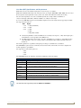
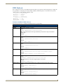
The NXB-KNX supports the following commonly used DPT (User Data) data lengths:
Supported DPT Data Lengths
Data Length
Description / Example
• 1-bit
DPT 1s are Boolean (switch)
• 2-bit
DPT 2s "1-bit controlled" (control)
• 4-bit (or
"Dim4")
DPT 3s "3-bit controlled" (used as on/off with dimmer step values)
• 1-Byte
DPT 5s "8-bit unsigned" (also DPT 4s, DPT 6s, DPT 200s, DPT 201s)
• 2-Byte
DPT 9s "2-octet float" (also DPT 7s, DPT 8s)
• 3-Byte
DPT 10s "time", and DPT 11s "date"
• 4-Byte
DPT 12s, DPT 13s, DPT 14s, DPT 15s "4-octet" (e.g. counter values)
• 14-Byte
DPT 16s "String" (also known as 'Text', 'HexText')
The character sets supported by KNX are ASCII and ISO 8859-1.
NXB-KNX KNX Communications Gateway
17
NetLinx Programming
Integrating with NetLinx
The NXB-KNX is a native ICSP device in NetLinx. The NXB-KNX associates each actuator (actor number) with a
corresponding Channel and Level mapping.
For example the value of actor 1 will map to Channel 1 / Level 1, and actor 52 will map to
Channel 52 / Level 52. These Channels and Levels are associated with the NXB-KNX device.
The default number of Channels and Levels supported by the NXB-KNX is 256.
If additional channels/levels are required to support additional actors the NXB-KNX can be configured to
allocate additional resources.
Refer to “ICSP [ch=n][,lv=m]” on page 24.
For a full listing and description of all supported NetLinx SEND_COMMANDS and String Feedback, refer
to the NetLinx SEND_COMMANDs section on page 21.
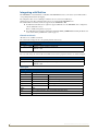
Channels and Levels
All addresses are available as channels.
The current value is mapped to the corresponding channels of the device.
Channels
Channel
Description
1 …n (0 < n < 3000)
Mapping of values irrespective of KNX type.
Default n = 256
All addresses are available as levels.
For every value change the current value is transmitted as level to the program, for instance to control a bargraph.
Levels
Level
Description
1 …n (0 < n < 3000)
Mapping of values irrespective of KNX type.
Default n = 256
Data Types
Data Types
18
Data Type
Description
Switch
Value '0' or '1'
e.g. Off - On
Control
Value '0' to '3'
e.g. forced operation
4 Bit
Value '0' to '15’
e.g. relative dimming - direction, interval
1 Byte
Value '0' to '255’
e.g. value absolute
2 Byte
Value '0' to '65535’
e.g. floating point value in EIS5 Notation
3 Byte
3 Byte
e.g. Date or Time
4 Byte
4 Byte
Text
1 to 14 ASCII Characters, String automatically filled with spaces
HEXText
1 to 14 Byte Hexvalue in ASCII-Notation
NXB-KNX KNX Communications Gateway
NetLinx Programming
Feedback
Runtime
All actuators/sensors can be configured to feedback to channels and levels via the ICSP command.
In addition feedback is generated in a readable ASCII display - depending on flags - meaning, the raw data are output as
time string, date string, floating point display etc.
Example:
Feedback of a 2Byte value, converted according to EIS5 standard (i.e. temperature value).
The corresponding actuator was entered in the filter table with flag "EIS5".
KNXAdd (dvKNX, 15, KNX2Byte, '1/0/201', "KNXEIS5")
The device will report two feedback with each value change (or as answer to a poll command):
String 1 from device (value change):
SET=15:3175'
String 2 from device:
EIS5=15:22.54'
or
String 1 from device (no value change):
VAL=15:3175'
String 2 from device:
EIS5=15:22.54'
Debugging
Example Status feedback:
**********************************************************************
* NXB-KNX: AMX NXB-KNX SN#xxxxxx
*
IP xxx.xxx.xxx.xxx
*
Version AmxKnxApp v2.0.15-KNX service unavailable
*
Running since Jun 18, 2009 2:24:02 PM
*
Servlet started
*
Total Mem: 22369792
*
Used Mem: 11975492
*
Free Mem: 10394300
*
KNX: KNX bus is not connected
*
Send delay is 50 ms
*
Poll delay is 1
*
------------------------*
# of 1Bit
: 13
*
# of 2Bit
: 0
*
# of 4Bit
: 2
*
# of 1Byte
: 4
*
# of 2Byte
: 3
*
# of 3Byte
: 2
*
# of 4Byte
: 0
*
# of Text
: 0
*
# of $Text
: 0
*
------------------------*
total
: 24
*
------------------------*
poll triggers : 8
* NetLinx: Online at Jun 18, 2009 2:24:32 PM
*
Device 13001
*
Master xxx.xxx.xxx.xxx
*
Channels = 256, Levels = 256
*
NXBCommandQ highwater = 38
*
Remote logging is on
* LogLevel: Info
**********************************************************************
NXB-KNX KNX Communications Gateway
19
NetLinx Programming
AMX_NXB_MOD Module
The AMX_NXB_MOD module is provided to facilitate remote logging from NXB-KNX as well as the "List Save" and
"List Load" functions.
The AMX_NXB_MOD module is integrated with the source code as follows:
DEFINE_MODULE 'AMX_NXB_MOD' nxbMod(dvKNX)
The parameters are as follows:
dvKNX - the physical interface for NXB-KNX, as a NetLinx D:P:S address
AMX_KNX_Updater Module
The AMX_KNX_Updater module is optional, and is provided to support implementations (e.g. legacy CommTec
projects) that use array values for feedback control.
the NXB-KNX supports channels and levels for each actuator. The Updater module is
provided to support legacy NetLinx code (which was designed to work with the
CommTec EIB device). Moving forward the Updater module could and should be
replaced with channel and level event driven feedback from the NXB-KNX, rather
than referencing the lKNX_Value array.
The AMX_KNX_Updater module is integrated with the source code as follows:
DEFINE_MODULE 'AMX_KNX_Updater' Updater(dvKNX, lKNX_Value)
The parameters are as follows:
dvKNX - the physical interface for NXB-KNX, as a NetLinx D:P:S address
1KNX_Value - the central value array of the KNX actuators (type LONG!). No strict size is required for the
array: it should be sized appropriately for site-specific optimal performance.
The 1KNX_Value array should be defined in the DEFINE_VARIABLE section:
DEFINE_VARIABLE
...
LONG lKNX_Value[3000]
...
Accessing Actuators On the KNX Bus
To access actuators on the bus, KNX Destination Addresses must be configured on the NXB-KNX. This is done via the
KNX_Table.axi file (included). This include file maps the Destination Address, type, poll conjunction and additional
features to an actor number between 1 and 3000. Communication with the actuators is accomplished via this actor
number.
KNX_Table.axi Include File
The KNX_Table.axi file contains the definition of all actuators on the KNX bus that will be controlled or monitored by
the NetLinx system, and is integrated in to NetLinx code via the following source code line:
#INCLUDE 'KNX_Table.axi'
Refer to the Sample Program section on page 30 for more information on the KNX Table and to review sample programs
that illustrate the following:
Structure of KNX Table With Functions From KNX_Tools.axi (see page 30)
Structure of KNX-Table with SEND_COMMANDS (see page 32)
KNX_Tools.axi Include File
Additionally, the KNX_Tools.axi file should be integrated to have easy access to commonly used functions, and is
integrated in to NetLinx code via the following source code line:
#INCLUDE 'KNX_Tools.axi'
Refer to the KNX_Tools.axi section on page 35 for more information, including a listing of the functions available in
KNX_Tools.axi.
20
NXB-KNX KNX Communications Gateway
NetLinx Programming
Analyzing Feedback
Data feedback is analyzed in a DATA_EVENT:
The feedback is always in STRING format
One DATA_EVENT is actuated per feedback (exactly one feedback in the DATA.TEXT)
In cases of multiple feedback, the corresponding number of events is actuated.
Channel feedback is analyzed in a CHANNEL_EVENT.
Level feedback is analyzed in a LEVEL_EVENT.
NetLinx SEND_COMMANDs
Commands to the module always take place per SEND_COMMAND to the device.
KNX_Tools.axi provides convenience function equivalents (See the Functions
Available In KNX_Tools.axi table on page 35).
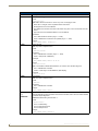
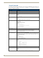
The NXB-KNX supports the following NetLinx commands:
NetLinx SEND_COMMANDs
Command
Description
ADD=
Adds a KNX group address to list.
Syntax:
ADD=<No>:<Type>:<GrpAdr>[:Flags]
Note: Flags are optional
Parameters:
• <No> = AMX Number of Actuator (range = 1 - 3000)
• <Type> = Actuator Type (Switch, Control, Dim4, 1Byte, 2Byte, 3Byte, 4Byte, Text, HexText)
• <GrpAdr> = KNX group address in 2 or 3 grouped display
• <Flags>:
EIS5 = Value is reported additionally as ASCII Float Value. The KNX Value is converted according
to EIS5 Standard (only valid for 2Byte Actuators)
Time = Value is reported additionally as ASCII Time (hh:mm:ss).
Note: Only valid for 3Byte Actuators
Date = Value is reported additionally as ASCII Date (MM/DD/YY).
Note: Only valid for 3Byte Actuators)
PS = Actuator is automatically polled with Start of AMX System
Note: Flags are separated by Commas
Examples:
SEND_COMMAND
SEND_COMMAND
SEND_COMMAND
SEND_COMMAND
ADR
dvKNX,'ADD=13:Switch:1/0/11'
dvKNX,'ADD=17:1Byte:4/7/12:PS'
dvKNX,'ADD=45:2Byte:3/0/11:EIS5'
dvKNX,'ADD=12:3Byte:2/1/101:TIME,PS'
Definition of output format of KNX group address (Main/Middle/Sub-group or
Main group/Sub-group).
Syntax:
ADR <Value>
Parameters:
<Value> = 2/3
Example:
SEND_COMMAND dvKNX,'ADR 3'
NXB-KNX KNX Communications Gateway
21
NetLinx Programming
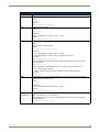
NetLinx SEND_COMMANDs (Cont.)
Command
Description
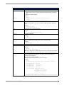
BIND=
Definition of Bind trigger.
Syntax:
BIND=<No>:<No2>
Note: BIND= will send instruction to <No2> only if <No> is changing its value
• When <No> is changed, <No2> is updated with the same value.
• No telegrams are sent on the KNX bus.
• The updated actor sends its new value to the master using Set= or Val= and Channel and Level
events.
• Typical use is to bind a feedback address to a control address.
Parameters:
• <No>= AMX Number of Actuator (range = 1 - 3000)
• <No2>= AMX Number of Actuator to be updated (range = 1 - 3000)
Example:
SEND_COMMAND dvKNX, 'BIND=24:11'
DATE=
Setting the Date.
Note: Only valid for 3Byte Actuators
Syntax:
DATE=<No>:<Datum>
Parameters:
• <No> = AMX Number of Actuator (range = 1 - 3000)
• <Date> - date (format = MM/DD/YY)
Example:
SEND_COMMAND dvKNX,'DATE=17:14/08/06'
Returns:
DATE=<No>:<Value>
Note: Is transmitted as ADDITIONAL feedback, if in actuator <No> the DATE flag is set.
• <No> = AMX Number of Actuator
• <Value> = Date string in format MM/DD/YY (AMX display)
Example:
DATE=17:08/14/06
DATE?
Request Date.
Note: Only valid for 3Byte Actuators
Syntax:
DATE?<No>
Parameters:
• <No> = AMX Number of Actuator
Example:
SEND_COMMAND dvKNX,'DATE?17'
DEBUGON
Activate debug reports
(or)
With activated debug report all actuators of the terminal are listed, which can be accessed via KNX.
This allows simple diagnostics.
DEBUGON=
DEBUGON enables debug and sets level = 1.
Syntax:
DEBUGON=<Level>
• Level 1: enables debug
• Level 2: adds actuator traces
• Level 3: adds ops traces
Example:
SEND_COMMAND dvKNX,'DEBUGON=1'
22
NXB-KNX KNX Communications Gateway
NetLinx Programming
NetLinx SEND_COMMANDs (Cont.)
Command
Description
DEBUGOFF
Deactivate debug reports
Syntax:
DEBUGOFF
Example:
SEND_COMMAND dvKNX,'DEBUGOFF'
DEL
Delete Actuator from Table
Syntax:
DEL <Value>
Parameters:
<Value> = AMX Number of Actuator (range = 1 - 3000)
Example:
SEND_COMMAND dvKNX,'DEL 3'
EIS5=
Setting an EIS5 value. Converts a floating-point value mapped in ASCII into 2Byte EIS5 value before
transfer.
Note: Only valid for 2Byte Actuators
Syntax:
EIS5=<No>:<floating point value>
Parameters:
• <No> = AMX Number of Actuator (range = 1 - 3000)
• <Floating Point Value> = Number (range = –671088.64 - 670760.96)
Example:
SEND_COMMAND dvKNX,'EIS5=12:24.3'
Returns: Feedback of a value in ASCII floating point display. The actuator value to be coded
according to EIS5.
EIS5=<No>:<Value>
Note: Is transmitted as ADDITIONAL feedback, if in actuator <No> the EIS5 flag is set.
• <No> = AMX Number of Actuator
• <Value> = Floating Point Value (String), converted according to EIS Specification
Example:
EIS5=12:20.25
EIS5?
Request EIS5 value. Converts the 2Byte raw data into ASCII string with floating point notation.
Note: Only valid for 2Byte Actuators
Syntax:
EIS5?<No>
Parameters:
• <No> = AMX Number of Actuator (range = 1 - 3000)
Example:
SEND_COMMAND dvKNX,'EIS5?12'
ERRORM=
Error message from NXB-KNX and/or bus.
(Feedback Only)
Note: The messages are only for information.
Each message may reflect an actual command, followed by the error condition encountered.
Example feedback:
ERRORM=(del 99) 99 not found
NXB-KNX KNX Communications Gateway
23
NetLinx Programming
NetLinx SEND_COMMANDs (Cont.)
Command
Description
GET=
Request Value of Actuator stored in the module
GET?
Note: Creates no Telegram on KNX (use for synchronization of master-to-master connection.
Syntax:
GET=<No>
GET?<No>
Parameters:
• <No> = AMX Number of Actuator (range = 1 - 3000)
Example:
SEND_COMMAND dvKNX,'GET=17'
HELP (or) /?
Output of available Terminal Commands
Syntax:
HELP (or)/?
Example:
SEND_COMMAND dvKNX,'HELP'
ICSP
Configures the number of channels and/or levels available.
• Requests n channels to be allocated.
• Requests m levels to be allocated.
Syntax:
ICSP [ch=n][,lv=m]
• Channel and level counts can be specified alone or together, and in any order.
• Use this command to override the default number of channels and/or levels.
• Default for Channels and Levels = 256.
Note: Caution is advised when expanding resources, since the Central Controller's resources need
to be considered.
Examples:
SEND_COMMAND dvKNX, 'icsp ch=128'
SEND_COMMAND dvKNX, 'icsp lv=512'
SEND_COMMAND dvKNX, 'icsp ch=256,lv=384'
LIST
List all entered actuators.
• Lists all entered actuators with AMX number, KNX group address, current value, set flags (if
applicable) and resulting additional feedback values.
• Lists sum of individual Types, sum of all actuators.
Syntax:
LIST
Example:
SEND_COMMAND dvKNX,'LIST'
LIST <No>
List one actuator (AMX number) with KNX group address, current value, set flags (if applicable) and
resulting additional feedback values.
Syntax:
LIST <No>
Parameters:
• <No> = AMX Number of Actuator (range = 1 - 3000)
Example:
SEND_COMMAND dvKNX,'LIST 17'
24
NXB-KNX KNX Communications Gateway
NetLinx Programming
NetLinx SEND_COMMANDs (Cont.)
Command
Description
LIST <No> <No2> List actuators in the range of <No> to <No2> (AMX numbers) with KNX group address, current
value, set flags (if applicable) and resulting additional feedback values
Syntax:
LIST <No>-<No2>
Parameters:
• <No> = AMX Number of Actuator (range = 1 - 3000) (Start)
• <No2> = AMX Number of Actuator (range = 1 - 3000) (End)
Example:
SEND_COMMAND dvKNX,'LIST 17-24'
LIST <Type>
List all entered actuators with AMX number, KNX group address, current value, set flags (if
applicable) and resulting additional feedback values.
Also provides a sum of all actuators of one Type.
Syntax:
LIST <Type>
Parameters;
• <Type> = Data Type, where:
SW or SWITCH - 1Bit Actuators
CO or CONTROL = 2Bit Actuators
D4 or DIM4 = 4Bit Actuators
1B or 1BYTE = 1Byte Actuators
2B or 2BYTE = 2Byte Actuators
3B or 3BYTE = 3Byte Actuators
4B or 4BYTE = 4Byte Actuators
Example:
SEND_COMMAND dvKNX,'LIST 1B'
LIST BIND
List all bind triggers with AMX number and KNX group address.
Syntax:
LIST BIND
Example:
SEND_COMMAND dvKNX, 'LIST BIND'
LIST FLAGS
List all actuators with assigned flags in table with KNX group address, current value, set flags (if
applicable) and resulting additional feedback values
Syntax:
LIST FLAGS
Example:
SEND_COMMAND dvKNX,'LIST FLAGS'
LIST GAPS
List free (unused) AMX numbers
Example:
SEND_COMMAND dvKNX,'LIST GAPS'
NXB-KNX KNX Communications Gateway
25
NetLinx Programming
NetLinx SEND_COMMANDs (Cont.)
Command
Description
LIST LOAD
Reads the entries in table written with LIST SAVE from CF and back.
• The current table is replaced with the read one.
• File name is optional.
• If no file name is specified, the default file name is used.
• Default file name: KNXTableNX.TXT
Note: In terminal connection with master the already available files on CF can be listed by entering
"List" (no SEND_COMMAND to device).
Syntax:
LIST LOAD [<Filename>]
Examples:
SEND_COMMAND dvKNX,'LIST LOAD'
SEND_COMMAND dvKNX,'LIST LOAD MyTable.txt'
LIST POLL
List all poll triggers with AMX number and KNX group address
Syntax:
LIST POLL
Example:
SEND_COMMAND dvKNX,'LIST POLL'
LIST SAVE
Writes the current KNX table, including poll trigger, as text file on CF.
This file can be edited with simple text editor.
The entries correspond with the structure of the regular table. Thus a table can be buffered, modified
(i.e. delete or add actuators) and finally reconstructed with LOAD (see above)
• File name is optional.
• If no file name is specified, the default file name is used.
• Default file name: KNXTableNX.TXT
Note: In monitor connection with master the already available files on CF can be listed by entering
"list" (no SEND_COMMAND to device).
Syntax:
LIST SAVE [<Filename>]
Examples:
SEND_COMMAND dvKNX,'LIST SAVE'
SEND_COMMAND dvKNX,'LIST SAVE MyTable.txt'
LIST SUM
List sum of all types, sum of all actuators.
Example:
SEND_COMMAND dvKNX,'LIST SUM'
LIST WATCH
List currently observed actuator with KNX group address, current value, set flags (if applicable) and
resulting additional feedback values
Example:
SEND_COMMAND dvKNX,'LIST WATCH'
POLL=
Request current value of actuator.
POLL?
Note: Creates a Telegram on KNX (For synchronization of master-to-master connection, only use
GET command).
Syntax:
POLL=<No>
POLL?<No>
Parameters:
• <No> = AMX Number of Actuator (range = 1 - 3000)
Examples:
SEND_COMMAND dvKNX,'POLL=17'
SEND_COMMAND dvKNX,'POLL?17'
26
NXB-KNX KNX Communications Gateway
NetLinx Programming
NetLinx SEND_COMMANDs (Cont.)
Command
Description
POLLDELAY=
Set pause between (automatic) value requests
Syntax:
POLLDELAY=<Value>
Parameters:
• <Value> = 0-2 (default = 1)
Note: 0 stands for very fast and should not be used, because otherwise the NXB-KNX would create
a high bus load. For installations with slow bus couplers (BCU1), the value 2 should be selected.
Example:
SEND_COMMAND dvKNX,'POLLDELAY=2'
POLLSTART
Triggers the pollstart action.
Requests current value of all actuators that have been configured with the 'PS' flag (see Add=).
When the optional actuator range is specified, only those actuators are affected.
The POLLDELAY setting affects the rate poll commands are sent to the KNX bus.
• This command is typically sent at the completion of the NXB-KNX configuration.
• This command is automatically executed by the NXB-KNX when the KNX bus is connected.
Syntax:
POLLSTART [<No>-<No2>]
Parameters:
• <No> = AMX Number of Actuator (range = 1 - 3000) (Start)
• <No2> = AMX Number of Actuator (range = 1 - 3000) (End)
Example:
POLLSTART
POLLSTART 25-75
SEARCH
Search for KNX group address
Syntax:
SEARCH <Groupaddress>
Note: Here 2 and 3 grouped mapping is accepted.
Caution: The addresses 7 / 715 and 7 / 2 /203 are i.e. identical KNX group addresses.
Example:
SEND_COMMAND dvKNX,'SEARCH 1/0/101'
SENDDELAY=
Delay between commands to KNX.
• Value is the time in 1/10 sec.
• The value 0 deactivated the delay.
Syntax:
SENDDELAY=<Value>
Examples:
SEND_COMMAND dvKNX,'SENDDELAY=0'
SEND_COMMAND dvKNX,'SENDDELAY=2'
NXB-KNX KNX Communications Gateway
27
NetLinx Programming
NetLinx SEND_COMMANDs (Cont.)
Command
Description
SET=
Set Actuator
Syntax:
SET=<No>:<Value>
Note: Observe actuator type in value range! The module limits the value range automatically to max
valid range of the accessed actuator.
Parameters:
• <No> = AMX Number of Actuator (range = 1 - 3000)
• <Value> = Value to be set
Example:
SEND_COMMAND dvKNX,'SET=5:1'
Returns: Report of a value change
SET=<No>:<Value>
Note: With the NXB_KNX_Updater module, the feedback array (type LONG) is automatically
updated, unchanged values are reported as VAL = (see below).
• <Nr> = AMX Number of Actuator
• <Value> = new Value of Actuator (raw data)
Example feedback:
SET=8:1
STATE?
Output of current module status in terminal
Example:
SEND_COMMAND dvKNX,'STATE?'
STATUS
List general status information for:
• AMX hardware
• KNX bus status
• Active KNX table
Syntax:
STATUS
Example:
SEND_COMMAND dvKNX,'STATUS'
TIME=
Set time
Note: Only valid for 3 Byte Actuators
Syntax:
TIME=<No>:<Time>
Parameters:
• <No> = AMX Number of Actuator (range = 1 - 3000)
• <Time> = Time in format hh:mm:ss
Example:
SEND_COMMAND dvKNX,'TIME=8:13:15:00'
28
NXB-KNX KNX Communications Gateway
NetLinx Programming
NetLinx SEND_COMMANDs (Cont.)
Command
Description
TIME?
Request of time
Note: Only valid for 3 Byte Actuators
Syntax:
TIME?<No>
Parameters:
• <No> = AMX Number of Actuator (range = 1 - 3000)
Example:
SEND_COMMAND dvKNX,'TIME?8'
Returns: Feedback of Time
TIME=<No>:<Value>
Note: Is transmitted as ADDITIONAL feedback, if in actuator <No> the time flag is set.
• <No> = AMX Number of Actuator
• <Value> = Time string (format = hh:mm:ss)
Example feedback:
Time=18:09:55:30
VAL=
(Feedback Only)
Feedback of an unchanged Value (for instance after GET or POLL):
VAL=<No>:<Value>
Variables:
• <No> = AMX Number of Actuator
• <Value> = Value of Actuator
VERSION
Output of current module version in Terminal
Example:
SEND_COMMAND dvKNX,'VERSION'
WATCH
Activate observation function for actuator.
All value changes are recorded on monitor with KNX group address, current value, set flags and
resulting additional feedback values.
Syntax:
WATCH <No>
Parameters:
• <No> = AMX Number of Actuator (range = 0 - 3000)
• 0 = deactivation of observation
Example:
SEND_COMMAND dvKNX,'WATCH 12'
WATCH OFF
Deactivate observation function for actuator
Syntax:
WATCH OFF
WHEN=
Definition of Poll trigger
Syntax:
WHEN=<No>:<No2>
Note: WHEN= will send instruction to <No2> only if <No> is changing its value.
Parameters:
• <No> = AMX Number of Actuator (range = 1 - 3000)
• <No2> = AMX Number of Actuator to be polled (range = 1 - 3000)
Example:
SEND_COMMAND dvKNX,'WHEN=32:12'
NXB-KNX KNX Communications Gateway
29
NetLinx Programming
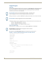
Sample Program
KNX Table
All actuators to be switched/set/controlled need to be provisioned on the NXB-KNX. In this example it is achieved with
the use of the KNX_Table.axi file. All provisioning commands are listed in the 'ONLINE' for the NXB-KNX device.
Other options are possible however this method is preferred. The method will guarantee that actuators will be
synchronized between the master and the NXB-KNX
Recommendation: Use the version with help function (example 1, see below). In this
version less typing errors will occur and the compiler can perform several checks.
Poll triggers will only be accepted by the NXB-KNX if the polling and polled addresses have already been defended.
Recommendation: define poll triggers after all actors have been defined.
Additionally, a snapshot of an active configuration may be saved and loaded to/from the master's internal file system.
Refer to “LIST SAVE [<Filename>]” on page 26.
Refer to “LIST LOAD [<Filename>]” on page 26.
Refer to “Example 3 - Load Configuration from File” on page 33.
Notes For Programming
Predefined functions are available for control to generate the SEND_COMMANDs for the NXB-KNX.
Recommendation: Use these functions, less typing errors will occur and the
compiler can perform several checks.
These functions are in the KNX_Tools.axi include file (see the KNX_Tools.axi section on page 35).
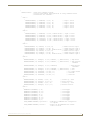
Example 1 - Structure of KNX Table With Functions From KNX_Tools.axi
MODULE_NAME='KNX_Table_NXB_A'(DEV dvNxbKnx)
DEFINE_VARIABLE
integer counter
float waitVal
DEFINE_START
Counter=0
waitVal = .2
#INCLUDE 'KNX_Tools.axi'
DEFINE_EVENT
DATA_EVENT [dvNxbKnx]
{
ONLINE: //Start configuration upload when NXB-KNX comes online.
{
wait 10 //1 second delay
{
counter = 1
}
}
}
DEFINE_PROGRAM
WAIT waitVal
30
NXB-KNX KNX Communications Gateway
NetLinx Programming
{
SWITCH(Counter)
//Send config command in groups.
//Caution avoid sending large quantities of config commands without
//intermittent wait intervals.
{
CASE 1:
{
KNXAdd(dvNxbKnx, 1, knxSWITCH, '1/1/0', "")
// Light 1 switch
KNXAdd(dvNxbKnx, 2, knxSWITCH, '1/1/1', "")
// Light 2 switch
KNXAdd(dvNxbKnx, 3, knxSWITCH, '1/1/2', "")
// Light 3 switch
KNXAdd(dvNxbKnx, 4, knxSWITCH, '1/1/3', "")
// Light 4 switch
KNXAdd(dvNxbKnx, 5, knxSWITCH, '1/1/4', "")
// Light 5 switch
KNXAdd(dvNxbKnx, 6, knxSWITCH, '1/1/5', "")
// Light 6 switch
}
CASE 2:
{
KNXAdd(dvNxbKnx, 7, knxSWITCH, '1/1/30', "knxPollstart") // Light 1 status
KNXAdd(dvNxbKnx, 8, knxSWITCH, '1/1/31', "knxPollstart") // Light 2 status
KNXAdd(dvNxbKnx, 9, knxSWITCH, '1/1/32', "knxPollstart") // Light 3 status
KNXAdd(dvNxbKnx, 10, eibSwitch, '1/1/33', "eibPollstart") // Light 4 status
KNXAdd(dvNxbKnx, 11, knxSWITCH, '1/1/34', "knxPollstart") // Light 5 status
KNXAdd(dvNxbKnx, 12, knxSWITCH, '1/1/35', "knxPollstart") // Light 6 status
}
CASE 3:
{
KNXAdd(dvNxbKnx, 20, knxDim4, '1/1/14', "")
// Dimmer relative light 5
KNXAdd(dvNxbKnx, 21, knx1Byte, '1/1/24', "")
// Dimmer absolute light 5
KNXAdd(dvNxbKnx, 22, knx1Byte, '1/1/44', "knxPollstart") // Dimmer feedback light 5
KNXAdd(dvNxbKnx, 24, knxDim4, '1/1/15', "")
// Dimmer relative light 6
KNXAdd(dvNxbKnx, 25, knx1Byte, '1/1/25', "")
// Dimmer absolute light 6
KNXAdd(dvNxbKnx, 26, knx1Byte, '1/1/45', "knxPollstart") // Dimmer feedback light 6
}
CASE 4:
{
KNXAdd(dvNxbKnx, 27, knx2Byte, '1/3/4', "knxEIS5, ',',knxPollstart") // Temp Actual
KNXAdd(dvNxbKnx, 28, knx2Byte, '1/3/5', "knxEIS5, ',',knxPollstart") // Temp Setpoint
readable
KNXAdd(dvNxbKnx, 29, knx2Byte, '1/3/6', "knxEIS5")
// Temp Setpoint
writeable
knx3Byte, '1/4/0', "knxTIME, ',',knxPollstart") // Time
knx3Byte, '1/4/1', "knxDATE, ',',knxPollstart") // Date
knxSWITCH, '1/1/200', "")
// All lights ON/OFF
knxSWITCH, '1/1/120', "")
// Scene ABC
knxSWITCH, '1/1/121', "")
// Scene XYZ
KNXAdd(dvNxbKnx, 31,
KNXAdd(dvNxbKnx, 32,
KNXAdd(dvNxbKnx, 33,
KNXAdd(dvNxbKnx, 38,
KNXAdd(dvNxbKnx, 39,
}
CASE 5:
{
KNXAdd(dvNxbKnx, 34, knxDim4, '1/2/0', "")
// Blind A Up / Down
KNXAdd(dvNxbKnx, 25, knx1Byte, '1/2/6', "")
// Blind B Position
KNXAdd(dvNxbKnx, 36, knxDim4, '1/2/1', "")
// Blind B Up / Down
KNXAdd(dvNxbKnx, 37, knx1Byte, '1/2/7', "")
// Blinds B Position
}
CASE 6:
{
KNXWhenPoll(dvNxbKnx, 5, 22)
// Polltrigger
KNXWhenPoll(dvNxbKnx, 20, 22)
// Polltrigger
KNXWhenPoll(dvNxbKnx, 21, 22)
// Polltrigger
KNXWhenPoll(dvNxbKnx, 22, 5)
// Polltrigger
KNXWhenPoll(dvNxbKnx, 6, 26)
// Polltrigger
KNXWhenPoll(dvNxbKnx, 24, 26)
// Polltrigger
KNXWhenPoll(dvNxbKnx, 25, 26)
// Polltrigger
KNXWhenPoll(dvNxbKnx, 26, 6)
// Polltrigger
SEND_COMMAND dvNxbKnx,"'pollstart'"
//Indicates to NXB-KNX that configuration
is complete
SEND_COMMAND dvNxbKnx,"'status'"
//report log from NXB-KNX with current
status of actors
}
NXB-KNX KNX Communications Gateway
31
NetLinx Programming
DEFAULT: Counter = 0
}// Switch
IF (Counter)
{
Counter ++
}// IF (Counter)
}// WAIT
Example 2 - Structure of KNX-Table with SEND_COMMANDS
MODULE_NAME='KNX_Table_NXB_A'(DEV dvNxbKnx)
DEFINE_VARIABLE
integer counter
float waitVal
DEFINE_START
Counter=0
waitVal = .2
#INCLUDE 'KNX_Tools.axi'
DEFINE_EVENT
DATA_EVENT [dvNxbKnx]
{
ONLINE: //Start configuration upload when NXB-KNX comes online.
{
wait 10 //1 second delay
{
counter = 1
}
}
}
DEFINE_PROGRAM
WAIT waitVal
{
SWITCH(Counter)
//Send config command in groups.
//Caution avoid sending large quantities of config commands
//without intermittent wait intervals.
{
CASE 1:
{
SEND_COMMAND
SEND_COMMAND
SEND_COMMAND
SEND_COMMAND
SEND_COMMAND
SEND_COMMAND
SEND_COMMAND
SEND_COMMAND
SEND_COMMAND
SEND_COMMAND
SEND_COMMAND
}
CASE 2:
{
SEND_COMMAND
SEND_COMMAND
SEND_COMMAND
SEND_COMMAND
SEND_COMMAND
SEND_COMMAND
SEND_COMMAND
SEND_COMMAND
SEND_COMMAND
32
DATA.DEVICE,
DATA.DEVICE,
DATA.DEVICE,
DATA.DEVICE,
DATA.DEVICE,
DATA.DEVICE,
DATA.DEVICE,
DATA.DEVICE,
DATA.DEVICE,
DATA.DEVICE,
DATA.DEVICE,
"'ADD=5:Switch:1/1/4'"
"'ADD=6:Switch:1/1/5'"
"'ADD=11:Switch:1/1/34:PS'"
"'ADD=12:Switch:1/1/35:PS'"
"'ADD=20:Dim4:1/1/14'"
"'ADD=21:1Byte:1/1/24'"
"'ADD=22:1Byte:1/1/44:PS'"
"'ADD=24:Dim4:1/1/15'"
"'ADD=25:1Byte:1/1/25'"
"'ADD=26:1Byte:1/1/45:PS'"
"'ADD=33:Switch:1/1/200'"
DATA.DEVICE, "'WHEN=5:22'"
DATA.DEVICE, "'WHEN=20:22'"
DATA.DEVICE, "'WHEN=21:22'"
DATA.DEVICE, "'WHEN=22:5'"
DATA.DEVICE, "'WHEN=6:26'"
DATA.DEVICE, "'WHEN=24:26'"
DATA.DEVICE, "'WHEN=25:26'"
DATA.DEVICE, "'WHEN=26:6'"
DATA.DEVICE,"'pollstart'"
//
//
//
//
//
//
//
//
//
//
//
//
//
//
//
//
//
//
//
//
Light 5 On/Off
Light 6 On/Off
Light 5 status
Light 6 status
Dimmer relative light
Dimmer relative light
Dimmer feedback light
Dimmer relative light
Dimmer absolute light
Dimmer feedback light
All lights ON/OFF
5
5
5
6
6
6
Polltrigger
Polltrigger
Polltrigger
Polltrigger
Polltrigger
Polltrigger
Polltrigger
Polltrigger
Indicates to NXB-KNX that configuration
is complete
NXB-KNX KNX Communications Gateway
NetLinx Programming
SEND_COMMAND DATA.DEVICE,"'status'"
//report log from NXB-KNX
with current status of actors
}
DEFAULT: Counter = 0
}
IF (Counter)
{
Counter ++
}
}
// Switch
// IF (Counter)
// WAIT
Example 3 - Load Configuration from File
The configuration can be read and generated from/to a file on the master file system. The reading of the file can for
instance be started in the ONLINE section of the interface.
...
DATA_EVENT[dvKNX]
{
ONLINE :
{
SEND_COMMAND dvKNX,'LIST LOAD MyTable.txt'
}
}
...
Comments at the end of a line must be separated by at least one space and are
initiated with "//".
Only one command per line is permitted.
Leading spaces are ignored.
Lines starting with "//" are ignored.
// Table written <DATE:TIME>
// ---------------------------// Actors / Addresses / Flags
// ---------------------------ADD=1:Switch:1/0/1
// Light 1 On/Off
ADD=2:Switch:1/0/2
// Light 2 On/Off
ADD=3:Switch:1/0/3
// Light 3 On/Off
ADD=4:Switch:1/0/11:PS
// Light 1 Status, poll on Start
ADD=5:Switch:1/0/12:PS
// Light 2 Status, poll on Start
ADD=6:Switch:1/0/13:PS
// Light 3 Status, poll on Start
ADD=7:Switch:1/0/21
// Scene 1+2
ADD=8:Switch:1/0/22
// Scene 3+4
ADD=9:Switch:1/0/31
// Blinds up/down
ADD=10:Switch:1/0/32
// Blinds shutter
ADD=11:Switch:1/0/111
// Dimmer On/Off
ADD=12:Dim4:1/0/112
// Dimmer relative
ADD=13:1Byte:1/0/113
// Dimmer absolute
ADD=14:1Byte:1/0/114:PS
// Dimmer read Value, poll on Start
ADD=15:2Byte:1/0/201:EIS5,PS
// analog Value, poll on Start
ADD=16:1Byte:1/0/203
// analog Value
ADD=17:3Byte:1/0/205:Time,PS
// Time, poll on Start
ADD=18:3Byte:1/0/206:Date,PS
// Date, poll on Start
// ------------// Polltrigger :
// ------------WHEN=1:2
// Polltrigger
WHEN=1:3
// Polltrigger
WHEN=11:14
// Polltrigger
WHEN=12:14
// Polltrigger
WHEN=13:14
// Polltrigger
WHEN=14:11
// Polltrigger
NXB-KNX KNX Communications Gateway
33
NetLinx Programming
Example 4 - Main Program
DEFINE_DEVICE
dvKNX = 13001:1:0
dvTP = 10002:1:0
DEFINE_CONSTANT
...
DEFINE_VARIABLE
VOLATILE LONG lKNX_Value[5000] // Feedback array
...
DEFINE_START
...
#INCLUDE 'KNX_Tools.axi'
#INCLUDE 'KNX_Table.axi'
DEFINE_MODULE 'AMX_KNX_Updater' Updater(dvKNX, lKNX_Value)
DEFINE_MODULE 'AMX_NXB_MOD' nxbMod(dvKNX)
//Module handles update
//of array for feedback control
//Module handles remote
//logging from NXB-KNX
//as well as facilitates
//List Save and
//List Load functions
DEFINE_EVENT
...
DATA_EVENT[dvKNX]
{
ONLINE :
{
SEND_COMMAND dvKNX,'LIST LOAD MyTable.txt'
}
}
BUTTON_EVENT[dvTP,1]
{
PUSH:
{
KNXSet(dvKNX,1,1)
KNXSet(dvKNX,16,128)
KNXSet(dvKNX,12,10)
}
RELEASE:
{
KNXSet(dvKNX,12,0)
}
}
CHANNEL_EVENT [dvKNX, 2]
{
ON:
{
ON[dvTp,31]
}
OFF:
{
OFF[dvTp,31]
}
}
// Light 1 ON
// Ballast to 50% Light 2
// Dimmer up Light 3
// Dimmer Stop Light 3
// Feedback Light 1
LEVEL_EVENT[dvKNX,21]
//Feedback Level light 2
{
SEND_LEVEL dvTP,1,LEVEL.VALUE
}
DEFINE_PROGRAM
34
NXB-KNX KNX Communications Gateway
NetLinx Programming
KNX_Tools.axi
We recommend not to use the send commands directly, but always use the functions of this include file. The compiler has
the opportunity to avoid typing errors already during compiling. Additional typing is avoided. This file also provides
absolute terms for relative dimming and blinds control:
// Constants
KNX_DIM_UP =
KNX_DIM_DN =
KNX_DIM_SP =
// Constants
KNX_DIR_UP
KNX_DIR_DOWN
KNX_DIR_STOP
for dimming Lights
9 //Brighter
1 //Darker
0 //Dimming Stop
for blind control
= 1 //UP
= 9 //Down
= 0 //Stop
Functions Available In KNX_Tools.axi
The following functions are available in file KNX_Tools.axi for programming:
Functions Available In KNX_Tools.axi
Function
Description
KNXSet
Sets actuator <actor No> to <Value>.
Syntax:
KNXSet (<NXB-KNX Device >,<actor No>,<Value>)
Note: The module limits the value range automatically to the maximum range of the selected
actuator type.
Example:
KNXSet (dvKNX,13,1)
KNXGet
Gets the value of actuator <actor No> to <Value> stored in module.
Syntax:
KNXGet (<NXB-KNX Device>,<actor No>)
Example:
nVAL = KNXGet (dvKNX,13)
KNXPoll
Polls the actuator <actor No>
Syntax:
KNXPoll (<NXB-KNX Device>,<actor No>)
Example:
KNXPoll (dvKNX,13)
KNXAdd
Adds entry to KNX table (description of parameters see above).
Syntax:
KNXAdd (<NXB-KNX Device>,<actor No>,<Type>,<Group Address>,<Flags>)
Example:
KNXAdd (dvKNX,13,KNX2Byte,'1/0/206',"knxPollstart")
KNXWhenPoll
Adds a poll trigger.
Syntax:
KNXWhenPoll (<NXB-KNX Device>,<actor No1>,<actor No2>)
Note: Value report from <actor No1> triggers polling on <actor No2>.
Example:
KNXWhenPoll (dvKNX,13,20)
KNXString2Array Converts comma separated Feedback from 14 Byte Hex into Integer Array with 14 chars.
Syntax:
KNXString2Array (<CHAR sArray[]>)
Example:
nArray = KNXString2Array (sArray)
KNXArray2String Converts Integer arrays with 14 chars to comma separated Array for 14 Byte Hex Type.
Syntax:
KNXArray2String (<Integer nArray[]>)
Example:
sArray = KNXArray2String (nArray)
NXB-KNX KNX Communications Gateway
35
NetLinx Programming
36
NXB-KNX KNX Communications Gateway
Cross-Line Communication
Cross-Line Communication
Overview
In many cases cross-line communication is required. In order to enable cross line communication a KNX programmer
will need to utilize the AMX NXB-KNX Virtual Device. This ETS device entry will serve as the
NXB-KNX device in ETS3.
The NXB-KNX is not a native KNX device and so it cannot be directly programmed from within ETS3. The AMX
NXB-KNX Virtual Device will allow a programmer to configure cross line communication between KNX devices and
the NXB-KNX.
The AMX NXB-KNX Virtual Device, once configured as desired, will allow ETS3 to calculate the appropriate routing
tables for line and area couplers.
Integrating the NXB-KNX Virtual Device Into An ETS3 Project
The following are the basic steps for integrating the NXB-KNX Virtual Device into an existing ETS project:
1. Open an existing ETS3 project.
2. Select File > Import to invoke the Import dialog (FIG. 23):
FIG. 23 ETS3 - Import dialog
3. Locate and select the NXB-KNX Virtual Device.vd4 file, and click Open.
This action invokes the Selective Import dialog (FIG. 24):
NXB-KNX KNX Communications Gateway
37
Cross-Line Communication
FIG. 24 Selective Import dialog
4. Verify that NXB-KNX is selected, and click Import.
Adding the Virtual Device to the ETS3 Project
Once the import procedure is complete, the virtual device must be added to the ETS3 project:
1. Identify the appropriate Area and Line at which the physical NXB-KNX will be connected, and
right-click on the Line name (heading) to access the context menu (FIG. 25):
FIG. 25 ETS3 - Topology in Default Project - context menu
2. Select Add Devices to invoke the Product Finder dialog (FIG. 26):
FIG. 26 Product Finder dialog
38
NXB-KNX KNX Communications Gateway
Cross-Line Communication
3. In the Product Finder dialog:
a. Select AMX from the Manufacturer drop down.
b. Click Find.
c. The NXB-KNX Virtual Device will appear in the search results.
d. Select NXB-KNX and click Insert.
e. Close the Product Finder dialog.
4. The NXB-KNX Virtual Device is indicated in the appropriate line (FIG. 27):
FIG. 27 ETS3 - Topology in Default Project indicating NXB-KNX
To facilitate cross-line and cross-area communication, all group addresses which do not originate from a device that is
located on the immediate line must be linked with the appropriate communication object on the NXB-KNX Virtual
Device.
For example, FIG. 28 indicates Light G, Light E and Light A (which are all of type 1 Bit) are linked with the NXB-KNX
Virtual Device 1 Bit communication object.
FIG. 28 ETS3 - Topology in Default Project indicating NXB-KNX
1. Create this linkage for all group addresses which do not originate within the line at which the NXB-KNX is
physically attached.
2. Repeat this process starting with the Adding the Virtual Device to the ETS3 Project for all additional NXB-KNX's
in your installation.
NXB-KNX KNX Communications Gateway
39
Cross-Line Communication
40
NXB-KNX KNX Communications Gateway
NetLinx Firmware Upgrades
NetLinx Firmware Upgrades
Overview
The NetLinx Studio software application (available for free download from www.amx.com) provides the ability to
transfer KIT firmware files to a NetLinx device such as the NXB-KNX.
To send firmware files, select Tools > Firmware Transfers, then select Send to NetLinx Device from the
sub-menu.
Before You Start
1. Establish the Firmware and device Application versions currently loaded on your NXB-KNX.
In the Admin Menu, look for the following entries:
Application Upgrade - Accesses the Application Upgrade Manager page.
Firmware Upgrade - Accesses the Firmware Upgrade Manager page.
The presence of these options in the Admin Menu indicates that your NXB-KNX unit is currently loaded with:
Firmware version 1.0.14 and
Application version 1.0.1
Admin Menu as it appears on
NXB-KNX units loaded with:
Firmware v1.0.14
Application v1.0.1
(requires upgrade to allow the unit to
function as a native NetLinx device)
Admin Menu as it appears on
NXB-KNX units loaded with
current Netlinx firmware.
Refer to the One-Time Upgrade of the NXB-KNX to a Native NetLinx
Device section on page 45 for instructions.
FIG. 29 Send To NetLinx Device dialog (NetLinx Studio)
Alternatively, you can identify the current firmware version via telnet (see Establishing
a Terminal Connection Via Telnet section on page 49) - the Welcome banner
indicates the current firmware version.
In this case, the NXB-KNX must be upgraded to the following Firmware and device Application versions (via .JAR
files), in order to allow the NXB-KNX to function as a native NetLinx Device:
Firmware version 1.0.36 (or higher)
Application version 2.0.15 (or higher)
Refer to the One-Time Upgrade of the NXB-KNX to a Native NetLinx Device section on page 45 for directions on
upgrading the Firmware and Application versions to these base minimum versions.
Once the unit has been upgraded, the NXB-KNX will function as a native NetLinx device, and all subsequent
Firmware upgrades are handled via NetLinx Studio, using KIT files (like any other native NetLinx device).
NXB-KNX KNX Communications Gateway
41
NetLinx Firmware Upgrades
2. Verify you have the latest version of NetLinx Studio on your PC. Use the Web Update option in NetLinx Studio’s
Help menu to obtain the latest version. Alternatively, go to www.amx.com and login as a Dealer to download the
latest version.
3. Go to www.amx.com and download the latest Firmware file. Firmware files are available to download from
www.amx.com - on the product’s page in the online catalog.
4. Verify that an Ethernet cable is connected from the NetLinx Master to the Ethernet Hub.
5. Verify that the NetLinx Master is powered On.
6. Determine the Device Number assigned to the target NXB-KNX.
By default, the Device Number assigned to the NXB-KNX is 0 (zero).
The Device Number can be viewed/edited in the NXB-KNX Configuration Manager - Device Configuration
Page (see the Device Configuration section on page 7 for details).
7. Launch NetLinx Studio and open the Online Device Tree.
Sending a Firmware (*.KIT) File To the NXB-KNX
Use the Firmware Transfers options in the Tools menu to update the firmware in the NXB-KNX. NetLinx Devices such
as the NXB-KNX use KIT files for firmware upgrades.
A Kit file (*.KIT) is a package of several files, all of which are required to upgrade the
firmware, and are available online via www.amx.com. Firmware download links are
provided in the relevant product page.
The Online Device Tree (Online Tree tab of the Workspace Window) displays information about each online
device, including the current firmware version.
Before attempting to upgrade the firmware, you must have the appropriate Kit file for your NXB-KNX.
To help alleviate system or network latency issues during file transfer, place KIT files in a "local" drive for
speedy throughput.
1. Choose Tools > Firmware Transfers > Send to NetLinx Device to open the Send To NetLinx Device dialog
(FIG. 30).
Browse for folder
containing the KIT file
FIG. 30 Send To NetLinx Device dialog (NetLinx Studio)
2. Click the Browse (...) button to navigate to the target directory in the Browse For Folder dialog (FIG. 31).
42
NXB-KNX KNX Communications Gateway
NetLinx Firmware Upgrades
FIG. 31 Browse For Folder dialog (NetLinx Studio)
The selected directory path is displayed in the Send To NetLinx Device dialog (Location text box).
Assuming that the specified target directory contains one or more KIT files, the KIT files in the selected
directory are displayed in the Files list box, with the file's last modified date and time (FIG. 32).
5600
FIG. 32 Send To NetLinx Device dialog (NetLinx Studio)
3. Select the appropriate *.KIT file from the Files list.
4. Enter the Device and System ID numbers for the NXB-KNX in the Device and System text boxes.
By default, the Device Number assigned to the NXB-KNX is 0.
Use the Online Device Tree to determine the device's assigned ID, if it has been changed.
5. Review the File, Connection, Address, and Target Device information before you send.
6. Click the Send button. You can watch the progress of the transfer in the Send to NetLinx Device dialog.
NetLinx Studio transfers the files to the NXB-KNX and then tells it to reboot. After it reboots, the NXB-KNX
actually goes through the upgrade process.
During the upgrade process, the Status LED blinks, and the NXB-KNX stays offline.
Once the upgrade is complete, the LED will stop blinking and the NXB-KNX will come online.
NXB-KNX KNX Communications Gateway
43
NetLinx Firmware Upgrades
If for any reason your Kit file transfer should fail, continue to retry the transfer until
you are successful. DO NOT reboot the NXB-KNX, or change connections until the
transfer is complete. Failure to complete this operation successfully may require a
factory repair of the NXB-KNX.
Additional Documentation
For additional information on using NetLinx Studio, refer to the NetLinx Studio online help and Operation/Reference
Guide (available at www.amx.com).
44
NXB-KNX KNX Communications Gateway
One-Time Upgrade of the NXB-KNX to a Native NetLinx Device
One-Time Upgrade of the NXB-KNX to a Native
NetLinx Device
Overview
This section describes the process of upgrading an older NXB-KNX to the latest version of NetLinx Firmware.
The initial release of the NXB-KNX operated as an IP Device (as opposed to a native NetLinx device). As an IP device,
the process of upgrading the unit to the latest firmware involves upgrading both the device Application and the
Firmware, via options in the Firmware Upgrade Manager (see FIG. 34 on page 46) and the Application Upgrade
Manager pages (see FIG. 35 on page 47).
Subsequent releases (and the current version) of the NXB-KNX operate as a native NetLinx device. As a NetLinx
device, the process of upgrading the unit is the same as for any typical NetLinx device: the latest NetLinx firmware KIT
file is downloaded from www.amx.com, and transferred to the NXB-KNX via the NetLinx Master, using NetLinx
Studio. See the NetLinx Firmware Upgrades section on page 41 for details.
Older NXB-KNX units that are still using the initial Application and Firmware versions can be upgraded to allow them
to function as a native NetLinx device.
Older NXB-KNX units that are using the initial Application and Firmware versions feature two Configuration pages that
are not included in the current version: the Application Upgrade Manager page and the Firmware Upgrade Manager
page (FIG. 33).
These two options only appear on early
versions of the NXB-KNX firmware
FIG. 33 Admin menu - early Firmware versions only
If these options do not appear in the Admin Menu, then your NXB-KNX unit is already a NetLinx device, and the
directions in this section does not apply.
Alternatively, you can identify the current firmware version via telnet (see Establishing
a Terminal Connection Via Telnet section on page 49) - the Welcome banner
indicates the current firmware version.
There are two aspects of the NXB-KNX that can be upgraded: the device Firmware and device Application, both of
which are normally updated via options in the Firmware Upgrade Manager (see FIG. 34 on page 46) and Application
Upgrade Manager pages (see FIG. 35 on page 47). However, special steps are required to perform an initial upgrade
from early versions of the NXB-KNX Application and Firmware.
The following steps describe upgrading the NXB-KNX from:
Firmware v1.0.14 and Application v1.0.1
to
Firmware v1.0.36 and Application v2.0.15
The Firmware upgrade must be performed before the Application upgrade.
NXB-KNX KNX Communications Gateway
45
One-Time Upgrade of the NXB-KNX to a Native NetLinx Device
Determining the Current Firmware Version Of the NXB-KNX
Select Firmware Upgrade from the Admin menu to open the Firmware Upgrade Manager page (FIG. 34). Use the
options on the page to upgrade the firmware on this NXB-KNX unit.
FIG. 34 Firmware Upgrade Manager page
This page allows you view information on the firmware version currently loaded on this unit, and to upload a firmware
.JAR file to the unit.
Another method of determining the current firmware version is to establish a telnet
session to the NXB-KNX. See Establishing a Terminal Connection Via Telnet section
on page 49.The Welcome banner in item 4 indicates the current firmware version.
Browse For the New Firmware Upload File
Select the Browse button to open a standard file display for traversing your PC's file structure, and selecting an
individual .JAR file.
The selected file name is displayed in the associated text box.
Click the Accept button to initiate the download of the selected .JAR file to the unit.
If the download fails for any reason, an error message is displayed indicating the failure.
If the download is successful, a message is displayed.
Click the Reboot button to initiate a system reboot. Firmware changes only take effect after a reboot.
System information will not be updated until after a system reboot.
If Current Firmware Version Is Lower Than v1.0.36
1. Select Firmware Upgrade from the Admin drop-down menu to open the Firmware Upgrade Manager page
(FIG. 34 on page 46).
2. Click Browse, and select the file: XXXX1.0.36.jar.
3. Click Accept.
4. When the upgrade is complete, reboot the NXB-KNX.
46
NXB-KNX KNX Communications Gateway
One-Time Upgrade of the NXB-KNX to a Native NetLinx Device
Determining the Current Application Version Of the NXB-KNX
Information on the current application version loaded on the device is displayed in the Application Upgrade Manager
page (FIG. 35).
FIG. 35 Application Upgrade Manager page
If Current Application Version Is Lower Than v2.0.15
1. Select Application Upgrade from the Admin drop-down menu to open the Application Upgrade page (FIG. 35 on
page 47).
2. Click Browse, and select the file XXXX2.0.15.jar.
3. Click Accept.
4. When the upgrade is complete, reboot the NXB-KNX.
Once the Application upgrade is performed, all subsequent upgrades will be
performed via Netlinx Studio supported Kit file upgrades. See the NetLinx Firmware
Upgrades section on page 41 for details.
NXB-KNX KNX Communications Gateway
47
One-Time Upgrade of the NXB-KNX to a Native NetLinx Device
48
NXB-KNX KNX Communications Gateway
Appendix A: Telnet Commands
Appendix A: Telnet Commands
Overview
The NXB-KNX supports Telnet communications. This type of terminal communication can be accessed remotely, via
TCP/IP.
Telnet is an insecure form of terminal communication, since it does not require a physical connection to the device to
connect. Further, the Telnet interface exposes information to the network (which could be intercepted by an unauthorized
network client).
It is recommended that you make initial configurations as well as subsequent
changes via the Web Console. Refer to the Configuration section on page 5.
Refer to the Terminal Commands section on page 50 for a listing of all commands available in a terminal session.
Establishing a Terminal Connection Via Telnet
1. In your Windows taskbar, go to Start > Run to open the Run dialog.
2. Type cmd in the Open field and click OK to open an instance of the Windows command interpreter (Cmd.exe).
3. In the CMD (command), type "telnet" followed by a space and the NXB-KNX’s IP Address info.
Example: >telnet XXX.XXX.XXX.XXX
4. Press Enter.
Unless Telnet security is enabled, a session will begin with a welcome banner:
Welcome to AMX v1.0.36 Copyright AMX LLC 2008
>
If Telnet security is enabled, type in the word login to be prompted for a Username and Password before
gaining access to the NXB-KNX.
5. Enter your username to be prompted for a password.
If the password is correct you will see the welcome banner.
If the password is incorrect, the following will be displayed:
Login: User1
Password: *****
Login not authorized. Please try again.
After a delay, another login prompt will be displayed to allow you to try again.
If after 5 prompts, the login information is not entered correctly, the following message will be displayed and
the connection closed:
Login not allowed. Goodbye!
If a connection is opened, but a valid a username / password combination is not
entered (i.e. just sitting at a login prompt), the connection will be closed after one
minute.
NXB-KNX KNX Communications Gateway
49
Appendix A: Telnet Commands
Terminal Commands
The Terminal commands listed in the following table can be sent directly to the NXB-KNX via Telnet terminal session.
In your terminal program, type "Help" or a question mark ("?") and <Enter> to access the Help Menu, and display the
Program port commands described below:
Terminal Commands
Command
Description
----- Help -----
(Extended diag messages are OFF)
? or Help
Displays this list of commands.
DATE
Displays the current date and day of the week.
Example:
>DATE
10/31/2004 Wed
DISK FREE
Displays the total bytes of free space available.
Example:
>DISK FREE
The disk has 2441216 bytes of free space.
DNS LIST <D:P:S>
Displays the DNS configuration of a specific device including:
• Domain suffix·
• Configured DNS IP Information
Example:
>DNS LIST [0:1:0]
Domain suffix:amx.com
The following DNS IPs are configured
Entry 1-192.168.20.5
Entry 2-12.18.110.8
Entry 3-12.18.110.7
ECHO ON|OFF
Enables/Disables echo (display) of typed characters.
GET JAVA HEAP
Display the amount of memory allocated for Java pool.
This is the current Java memory heap size as measured in Megabytes.
Example: a value of 5M = 5 MB.
GET ETHERNET MODE
Displays the current ethernet configuration setting.
Settings are either "auto" in which the ethernet driver will discover it's settings based on
the network it is connected to OR <speed> and <duplex> where speed is either 10 or 100
and duplex is either full or half.
Example:
>GET ETHERNET MODE
Ethernet mode is auto.
Note: See SET ETHERNET MODE.
GET IP
Displays the current IP configuration.
Example:
>GET IP
IP Settings
HostName
Type
IP Address
Subnet Mask
Gateway IP
MAC Address
MLK_INSTRUCTOR
DHCP
192.168.21.101
255.255.255.0
192.168.21.2
00:60:9f:90:0d:39
IPSEC ON|OFF|STATUS
Enables/Disables IPSec security or displays current setting.
MEM
Displays the largest free block of the NXB-KNX’s memory.
Example:
>MEM
The largest free block of memory is 11442776 bytes.
50
NXB-KNX KNX Communications Gateway
Appendix A: Telnet Commands
Terminal Commands (Cont.)
Command
MSG ON|OFF
Description
Enables/Disables extended diagnostic messages.
• MSG On sets the terminal program to display all messages generated by the NXBKNX.
• MSG OFF disables the display.
Example:
> MSG ON
Extended diagnostic information messages turned on.
> MSG OFF
Extended diagnostic information messages turned off.
PING [ADDRESS]
Pings an address (IP or URL), to test network connectivity to and confirms the presence of
another networked device. The syntax is just like the PING application in Windows or
Linux.
Example:
>ping 192.168.29.209
192.168.29.209 is alive.
PWD
Displays the name of the current directory.
Example:
pwd
The current directory is doc:
REBOOT
Reboots the NXB-KNX.
Example:
>REBOOT
Rebooting...
RELEASE DHCP
Releases the current DHCP lease for the NXB-KNX.
Note: The NXB-KNX must be rebooted to acquire a new DHCP lease.
Example:
>RELEASE DHCP
SECURITY SETUP
Modify system security settings.
SET DATE
Prompts you to enter the new date for the NXB-KNX.
Example:
>SET DATE
Enter Date: (mm/dd//yyyy) ->
Note: Due to the absence of a battery-backed real-time clock, setting the current date is
only valid for the life of the current run. When the unit is rebooted, the date will be lost.
SET DNS
Sets up the DNS configuration. This command prompts you to enter a Domain Name,
DNS IP #1, DNS IP #2, and DNS IP #3. Then, enter Y (yes) to approve/store the
information in the NXB-KNX.
Entering N (no) cancels the operation.
Note: The device must be rebooted to enable new settings.
Example:
>SET DNS
-- Enter New Values or just hit Enter to keep current settings -Enter
Enter
Enter
Enter
Domain Suffix:
DNS Entry 1 :
DNS Entry 2 :
DNS Entry 3 :
amx.com
192.168.20.5
12.18.110.8
12.18.110.7
You have entered: Domain Name: amx.com
DNS Entry 1: 192.168.20.5
DNS Entry 2: 12.18.110.8
DNS Entry 3: 12.18.110.7
Is this correct? Type Y or N and Enter -> Y
Settings written. Device must be rebooted to enable new settings
NXB-KNX KNX Communications Gateway
51
Appendix A: Telnet Commands
Terminal Commands (Cont.)
Command
SET JAVA HEAP
Description
Set the amount of memory allocated for the Java pool. This is the current Java memory
heap size as measured in Megabytes.
• Valid values = 5M - 35M
• Recommended default = 32M
Note: This setting does not take effect until the next reboot.
SET ETHERNET MODE
<CMD>
This command sets the current Ethernet configuration settings - auto OR speed =
10 | 100, duplex = full | half.
Example:
set ethernet mode auto
set ethernet mode speed=100 duplex=full
Note: See GET ETHERNET MODE.
SET FTP PORT
Enables/Disables the NXB-KNX’s IP port listened to for FTP connections.
Note: The device must be rebooted to enable new settings.
Example:
>SET FTP PORT
FTP is enabled
Do you want to enable (e) or disable (d) FTP (enter e or d):
FTP enabled, reboot the NXB-KNX for the change to take affect.
SET HTTP PORT
Sets the NXB-KNX’s IP port listened to for HTTP connections.
Note: The device must be rebooted to enable new settings.
Example:
>SET HTTP PORT
Current HTTP port number = 80
Enter new HTTP port number (Usually 80) (0=disable HTTP):
Setting HTTP port number to
New HTTP port number set, reboot the NXB-KNX for the change to take
affect.
SET HTTPS PORT
Sets the NXB-KNX’s IP port listened to for HTTPS connections.
Note: The device must be rebooted to enable new settings.
Example:
>SET HTTPS PORT
Current HTTPS port number = 443
Enter new HTTPS port number (Usually 443) (0=disable HTTPS):
Once you enter a value and press the ENTER key, you get the following message:
Setting HTTPS port number to
New HTTPS port number set, reboot the NXB-KNX for the change to take
affect.
52
NXB-KNX KNX Communications Gateway
Appendix A: Telnet Commands
Terminal Commands (Cont.)
Command
SET IP
Description
Sets the IP configuration. Enter a Host Name, Type (DHCP or Fixed), IP Address, Subnet
Mask, and Gateway IP Address.
Note: For NetLinx Central Controllers, the "Host Name" can only consist of alphanumeric
characters.
• Enter Y (yes) to approve/store the information into the NXB-KNX.
• Enter N (no) to cancel the operation.
Note: The device must be rebooted to enable new settings.
Example:
>SET IP
--- Enter New Values or just hit Enter to keep current settings --Enter Host Name:
MLK_INSTRUCTOR
Enter IP type. Type D for DHCP or S for Static IP and then Enter:
DHCP
Enter Gateway IP:
192.168.21.2
You have entered: Host Name
MLK_INSTRUCTOR
Type
DHCP
Gateway IP 192.168.21.2
Is this correct? Type Y or N and Enter -> y
Settings written. Device must be rebooted to enable new settings.
SET LOG COUNT
Sets the number of entries allowed in the message log.
Note: The device must be rebooted to enable new settings.
Example:
>SET LOG COUNT
Current log count = 1000
Enter new log count (between 50-10000):
Once you enter a value and press the ENTER key, you get the following
message:
Setting log count to
New log count set, reboot the NXB-KNX for the change to take affect.
SET SSH PORT
Sets the NXB-KNX’s IP port listened to for SSH connections.
Note: The device must be rebooted to enable new settings.
Example:
>SET SSH PORT
Current SSH port number = 22
Enter new SSH port number (Usually 22) (0=disable SSH):
Once you enter a value and press the ENTER key, you get the following message:
Setting SSH port number to 22
New SSH port number set, reboot the NXB-KNX for the change to take
affect.
SET TELNET PORT
Sets the NXB-KNX’s IP port listened to for Telnet connections.
Note: The NXB-KNX must be rebooted to enable new settings.
Example:
>SET TELNET PORT
Current telnet port number = 23
Enter new telnet port number (Usually 23)(0=disable Telnet):
Once you enter a value and press the ENTER key, you get the following message:
Setting telnet port number to 23
New telnet port number set, reboot the NXB-KNX for the change to
take affect.
NXB-KNX KNX Communications Gateway
53
Appendix A: Telnet Commands
Terminal Commands (Cont.)
Command
SET TIME
Description
Sets the current time.
Example:
>SET TIME
Enter Date: (hh:mm:ss) ->
Note: Due to the absence of a battery-backed real-time clock, setting the current time is
only valid for the life of the current run. When the unit is rebooted, the time will be lost.
SHOW LOG
Displays the log of messages stored in the NXB-KNX's memory.
The NXB-KNX logs all internal messages and keeps the most recent messages.
The log contains:·
•
•
•
•
Entries starting with first specified or most recent
Date, Day, and Time message was logged
Which object originated the message
The text of the message:
SHOW LOG [start] [end]
SHOW LOG ALL
- <start> specifies message to begin the display.
- If start is not entered, the most recent message will be first.
- If end is not entered, the last 20 messages will be shown.
- If <ALL> is entered, all stored messages will be shown, starting with the most recent.
Example:
>SHOW LOG
Message Log for System 50 Version: v2.10.75
Entry
Date/Time
Object
Text
----------------------------------------------------------------1: 11-01-2001 THU 14:14:49 ConnectionManager
Memory Available = 11436804 <26572>
2: 11-01-2001 THU 14:12:14 ConnectionManager
Memory Available = 11463376 <65544>
3: 11-01-2001 THU 14:10:21 ConnectionManager
Memory Available = 11528920 <11512>
4: 11-01-2001 THU 14:10:21 TelnetSvr
Accepted Telnet connection:socket=14 addr=192.168.16.110 port=2979
5: 11-01-2001 THU 14:05:51 Interpreter
CIpEvent::OnLine 10002:1:50
6: 11-01-2001 THU 14:05:51 Interpreter
CIpEvent::OnLine 128:1:50
7: 11-01-2001 THU 14:05:51 Interpreter
CIpEvent::OffLine 128:1:50
8: 11-01-2001 THU 14:05:51 Interpreter
CIpEvent::OnLine 96:1:50
9: 11-01-2001 THU 14:05:51 Interpreter
CIpEvent::OffLine 96:1:50
10: 11-01-2001 THU 14:05:51 Interpreter
CIpEvent::OnLine 128:1:50
11: 11-01-2001 THU 14:05:51 Interpreter
CIpEvent::OnLine 96:1:50
12: 11-01-2001 THU 14:05:51 Interpreter
CIpEvent::OnLine 5001:16:50
13: 11-01-2001 THU 14:05:51 Interpreter
CIpEvent::OnLine 5001:15:50
14: 11-01-2001 THU 14:05:51 Interpreter
SHOW HEAP
Displays heap usage statistics.
SHOW MEM
Displays the memory usage for all memory types.
TIME
Displays the current time on the NXB-KNX.
Example:
>TIME
13:42:04
54
NXB-KNX KNX Communications Gateway
Appendix B: Troubleshooting
Appendix B: Troubleshooting
Overview
AMX recommends activating debugging mode during diagnostics to display additional error messages. This is activated
with monitor command "DEBUGON".
The following table provides tips for error definition, in case it does not work. This serves a quick error analysis ON
SITE.
Troubleshooting
Error
Proposed solution / error definition
No controls possible, no feedback
Ensure NXB-KNX is detected in Netlinx Studio online tree.
No controls possible, no feedback, Enter command "List" in debug mode.
according to "Status" the NXB-KNX • Are all addresses entered?
is detected
• Are feedback values displayed?
Try to switch several addresses directly with "SET" (e.g. light). If it works, there is
probably an error in the AMX program.
If also no access is possible (Is the light still on?), the reason is probably wrong
group addresses.
NXB-KNX does not appear in the
NetLinx Studio OnLine Tree view
Confirm the NXB-KNX is powered on and connected to your network using an
approved PoE cable.
Use a zero-config client, like Internet Explorer's Bonjour or NetLinx Studio's ZeroConfig tab, to access the NXB-KNX Configuration Manager.
• Check the NXB-KNX IP Settings match your network configuration.
• Check the NXB-KNX Master Connection settings match your AMX Master
controller configuration.
Confirm the current NXB-KNX connection status by viewing the
NXB-KNX status banner.
• Obtain the NXB-KNX ip address using a zero-config client.
• Establish a telnet session with the NXB-KNX.
• Enable display of diagnostic messages by typing 'msg on all'.
• The NXB-KNX status banner will refresh every 15 minutes.
• Or, use the 'show log' command to display the message log.
NXB-KNX date/time is incorrect
Use the NXB-KNX Configuration Manager Clock Manager to configure the NXBKNX time/date settings.
• It is recommended that the NXB-KNX time/date settings match its AMX Master
controller time/date settings.
• e.g. The NXB-KNX and the AMX Master controller both use the same NIST
server.
NXB-KNX appears in the NetLinx
Studio OnLine Tree view, but no
control or feedback is possible
NXB-KNX KNX Communications Gateway
Confirm the NXB-KNX device number shown in the NetLinx Studio OnLine Tree
view matches your NetLinx project's NXB-KNX device number definition.
Use the NXB-KNX Configuration Manager Device Configuration to change the
NXB-KNX device number.
55
Appendix B: Troubleshooting
Troubleshooting
Error
Proposed solution / error definition
Responses to interactive
commands, e.g. 'list', are not
displayed.
Responses to interactive commands are displayed only when the NXB-KNX log
level is debug.
Confirm the NXB-KNX log level is debug.
• Establish a telnet session with the NXB-KNX.
• Enable display of diagnostic messages by typing 'msg on all'.
• The NXB-KNX status banner will refresh every 15 minutes.
• Or, use the NXB-KNX 'status' command to force the status banner to display.
• Or, use the 'show log' command to display the message log.
Use the NXB-KNX 'debugon' command to set the log level to debug.
• It is recommended to return the NXB-KNX to its operational log level of info when
the interactive session is completed.
• Use the NXB-KNX 'debugoff' command to return the log level to info.
Control and/or feedback
is not working
Confirm the NXB-KNX configuration by using the 'list' interactive command.
• Do all expected actors appear in the list?
• Do all expected group addresses appear in the list?
• Is the group address assigned to the expected actor number? Remember, the
actor number is also the channel and level number.
• Are all group addresses configured using the correct data type e.g. 'Switch'?
Confirm the KNX device configuration parameters by using the ETS program.
Confirm the KNX device is connected to the KNX bus.
Confirm the NXB-KNX is connected to the KNX bus.
56
NXB-KNX KNX Communications Gateway
Appendix B: Troubleshooting
NXB-KNX KNX Communications Gateway
57
4/14 ©2014 AMX. All rights reserved. AMX and the AMX logo are registered trademarks of AMX. AMX reserves the right to alter specifications without notice at any time.
It’s Your World - Take Control™
3000 RESEARCH DRIVE, RICHARDSON, TX 75082 USA • 800.222.0193 • 469.624.8000 • 469-624-7153 fax • 800.932.6993 technical support • www.amx.com