1
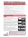
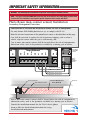
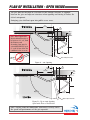
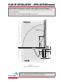
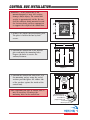
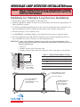
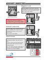
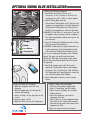
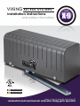
PLAN
PLAN OF
OF INSTALLATION
INSTALLATION -- OPEN
OPEN INSIDE
INSIDE
The gate must be installed in a location so that enough clearance is supplied
between the gate and adjacent structures when opening and closing to reduce the
risk of entrapment.
Swinging gates shall not open into public access areas.
C:
23-1/2"
Outside
Gate in Closed Position
Note: When application
dictates dimension (A) to
be between 12”-18”, both
the Primary and
Secondary arms may be
extended EQUALLY, up to
6” each. Do not allow the
condition below to occur.
G:
4.33"
Ref.
H:
2.55"
Ref.
A: 15-3/4" Max.
90°
Opening
F:
15-1/2"
Min.
Gate in Open Position
Figure A – 90° Opening
7-1/4"
Max.
Outside
C:
19-1/2"
G:
4.33"
Ref.
H:
2.55"
Ref.
Gate in Closed Position
120°
Opening
F:
15-1/2"
Min.
Inside
Gate in Open Position
Figure B – Up to 120° Opening
Open Inside Plans of Installation
Note: Varying from the dimensions shown may severely affect
the speed and performance of the gate operator.
10
TECHNICAL SUPPORT 1 800 908 0884