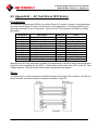
1
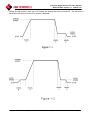
(2003-01-31)
Controlinc Digital Futronic VIII User Manual
Model DF320A Version 1.0 (2003-01-31)
Table of Contents
1. Overview ........................................................................................................................... 1
1.1. Introduction.................................................................................................................................................. 1
1.2. Product Description..................................................................................................................................... 1
1.2.1. Mechanical Actuator Assembly with M2CP Electrical Enclosure ...................................................................... 1
1.2.2. Variable Frequency Controller Unit (VFC)......................................................................................................... 2
1.2.3. Modular Construction.......................................................................................................................................... 2
1.3. Theory of Operation .................................................................................................................................... 3
1.3.1. Programmable Speed and Accel/Decel Rates...................................................................................................... 3
1.3.2. Brakes.................................................................................................................................................................. 3
1.3.3. Position Control................................................................................................................................................... 3
1.3.4. Speed and Acceleration / Deceleration Control................................................................................................... 4
1.3.5. Stall Prevention ................................................................................................................................................... 4
1.3.6. Stall Detection ..................................................................................................................................................... 4
2. Installation ........................................................................................................................ 6
2.1. Conduit Entries............................................................................................................................................ 6
2.2. Wiring ........................................................................................................................................................... 7
2.2.1. Power Wiring ...................................................................................................................................................... 7
2.2.2. Control Wiring .................................................................................................................................................... 7
3. Setup and Calibration...................................................................................................... 8
3.1. Open and Close Limit Switches.................................................................................................................. 8
3.2. Auxiliary Inputs and Outputs..................................................................................................................... 8
3.3. Torque Switches........................................................................................................................................... 8
3.4. DCM320A Module Setup ............................................................................................................................ 9
3.5. VFC Configuration.................................................................................................................................... 11
4. Application Tuning ........................................................................................................ 12
4.1. Bandwidths................................................................................................................................................. 12
4.2. Decel Rates ................................................................................................................................................. 12
4.3. Speeds.......................................................................................................................................................... 12
5. Storage Instructions....................................................................................................... 13
5.1. Short Term Storage ................................................................................................................................... 13
5.2. Long Term Storage.................................................................................................................................... 13
6. Appendices ...................................................................................................................... 14
6.1. Appendix A … Baldor Series 15J............................................................................................................. 14
6.2. Appendix C Baldor Series 15H ............................................................................................................ 15
6.3. Appendix B … AC Tech Drives (SCF Series) ......................................................................................... 16
Copyright © 2000 EIM Company, Inc
13840 Pike Road
Missouri City, TX 77489
(281) 499-1561
Page ii
Controlinc Digital Futronic VIII User Manual
Model DF320A Version 1.0 (2003-01-31)
1. Overview
1.1. Introduction
This manual covers basic installation, wiring, configuration, and operation of EIM Digital Futronic VIII
precision positioning controller installed in EIM 2000 Series valve actuators. The Futronic VIII controller
uses a Variable Frequency Controller (VFC) to control the motor. This manual describes the theory of
operation and details the settings required for VFC operation of EIM’s Digital Control Module (DCM)
320A with a VFC motor controller. A separate manual is provided with the VFC drive and DCM 320A.
Refer to the VFC manual for setup and programming the VFC drive. Refer to manual E796 for
mechanical setup and limit switch adjustments of the Series 2000 valve actuator. The valve actuator is
based on EIM's Modular Modular Control Package (M2CP). The VFC drive may be internal to the
actuator, close coupled to the actuator or remote mounted. EIM will wire all internal and close coupled
systems while others wire remote mounted drives during installation. Appendix A covers wiring and
programming requirements specific to each drive series provided with the actuator.
Note: Some functions, features, and options described in this manual may be disabled or may not be
present in some project specific systems.
1.2. Product Description
EIM's Digital Futronic VIII system is a precision positioner using standard 3-Phase AC motors with EIM
actuators. Futronic VIII is based on EIM's standard 320A digital control module used for many years in
EIM’s digital networks and analog control systems. The Digital Futronic VIII package uses a unique
terminal board module (TBM320A-VFC) that replaces the connection to a conventional motor starter
with a connector used for connecting to the VFC. The VFC replaces the motor reversing contactor and
inherently provides all solid state motor control and auto phase correction.
1.2.1. Mechanical Actuator Assembly with M2CP Electrical Enclosure
The main drive unit provides mechanical power to operate the valve, damper, or other positioning
device. This assembly contains the motor, gear box, hand wheel, declutch, valve position feedback
potentiometer, limit switches, and torque switches. The Modular Modular Control Package (M2CP) is
the electronic controls part of this assembly. Refer to manual E796 for instructions on setting limit and
torque switches. The M2CP consists of a DCM 320A TBM320A-VFC, Limit Switch Module(LSM), and
control voltage transformer. The M2CP accepts a 4-20mA command signal or a digital setpoint and
provides digital position feedback via the network or an optional 4-20mA signal. It also provides control
signals to the VFC based on the difference between the position command signal (setpoint) and the
position feedback signal. Control signals from the M2CP to the VFC include speed, and direction to the
VFC.
Copyright © 2000 EIM Company, Inc
13840 Pike Road
Missouri City, TX 77489
(281) 499-1561
Page 1
Controlinc Digital Futronic VIII User Manual
Model DF320A Version 1.0 (2003-01-31)
1.2.2. Variable Frequency Controller Unit (VFC)
Speed of a 3-phase motor is controlled by frequency of the applied power. Operating at 60 Hz will
cause motor to run at normal full speed. Operating at a frequency less than 60 Hz will cause motor to
run a percentage of normal full speed. The VFC can control frequency of the power output from 0.1 Hz
to 400 Hz in 0.1 Hz increments. Variable Frequency Controller (VFC) receives 50 - 60 Hz, single or 3phase AC electrical power input and supplies power to the motor of the actuator on command from the
M2CP containing the DCM320A. The AC input power is converted to DC and stored on a bank of
capacitors. The DC power is converted back into 3-phase AC power by switching the transistor outputs
at a high frequency, typically 10KHz. Power is switched in an alternating pattern from positive polarity to
negative polarity to positive polarity, etc. at the frequency rate programmed by the microprocessor to
determine motor speed. Switching polarity is done in a sequence on each of the three phases at a
delay time equal to 120 degrees separation between phases based on the frequency. Frequency is
normally ramped up at a programmed acceleration rate from one frequency to the next higher
frequency. Frequency is also ramped down at a programmed deceleration rate from a higher frequency
to the next lower frequency. Programming the VFC is typically via a front panel keyboard/display
terminal. Some drives may also support programming via special software on a PC. The VFC may be
internal, close coupled or enclosed in a separate enclosure remote to actuator. The VFC must be
located within 500 feet of the actuator. Refer to the VFC operations manual supplied with the VFC
drive for setup and programming instructions.
1.2.3. Modular Construction
Extensive use of surface mount technology (SMT) has allowed EIM to maintain single board
construction of the DCM320A which plugs into the M2CP. The digital control module may be replaced
by plugging in a replacement module without disabling local control functions. EIM has maintained
mechanical gearing of limit and torque switches which keep in step with movement of the actuator
when power is removed without battery back-up. Local control pushbuttons and selector switches are
not dependent on the DCM320A. The actuator is able to operate in the manual mode even while the
DCM320A is removed.
Copyright © 2000 EIM Company, Inc
13840 Pike Road
Missouri City, TX 77489
(281) 499-1561
Page 2
Controlinc Digital Futronic VIII User Manual
Model DF320A Version 1.0 (2003-01-31)
1.3. Theory of Operation
1.3.1. Programmable Speed and Accel/Decel Rates
The EIM Futronic VIII system uses only two speeds, normal and slow. The speeds are programmable
at the VFC. Normal speed is typically set as the standard full speed of the motor at 50 or 60 Hz but may
be set at some other frequency. Selection of the two speeds is dependent on the application
requirements. The system has two independently programmable acceleration rates. One is from stop to
slow speed and the other is from slow speed to normal speed. The system also has two independently
programmable deceleration rates. One is from normal speed to slow speed and the other is from slow
speed to a minimum frequency at which time electric motor brake may be applied. (See Figures 1-1
and 1-2)
1.3.2. Brakes
Much of the required braking is applied to the motor by the VFC absorbing regenerated energy from the
motor during deceleration. Brakes to stop the motor more quickly or under higher load conditions can
be in the form of a DC injection brake or a dynamic brake. The type of braking to use is dependent on
the application. Selection of the type of brakes is programmable at the VFC. DC injection brake
operates by applying the high frequency signal to the motor in only one polarity. Dynamic brakes
operate by dumping excessive regenerated energy from the motor into a resistive load, e.g. a bank of
high power rated resistors. If dynamic brakes are required, some VFCs require an external braking unit
to be added to the system.
1.3.3. Position Control
Precision position control is provided by the DCM320A. This module has a sensitivity of + 0.1%.
Precision of control is adjustable by setting the Position Control bandwidth in the DCM320A. The
DCM320A can provide control precision of ±.25% or better in most applications. When used in
conjunction with the VFC, the system has a repeatability of 0.1% or better in most applications. The
DCM320A has an adjustment for modulation delay time. This provides a delay from the last time the
valve moved to the next time it is allowed to move, preventing valve plugging. This time is normally set
to zero in high-speed modulating applications. The DCM320A also has zero and span calibration
adjustments for the 4-20mA feedback signal. DCM320A setup can be done with EIM Controls CCU
software, or with DIP switches. For DIP switch configuration refer to the Controlinc Quick Startup
Guide.
The DCM320A module provides Open and Close outputs to motor controller VFC to control position of
actuator or valve to within the adjusted control bandwidth. This is accomplished by comparing valve
position feedback signal with position command (setpoint) signal. If a difference between the two
signals is greater than bandwidth setting, an Open or Close digital output is generated. Open or Close
direction is determined by the difference between the two signals being either positive or negative. The
two digital outputs for Open and Close are fed to the VFC interface circuitry, providing isolation and
proper electrical interface to the VFC.
Copyright © 2000 EIM Company, Inc
13840 Pike Road
Missouri City, TX 77489
(281) 499-1561
Page 3
Controlinc Digital Futronic VIII User Manual
Model DF320A Version 1.0 (2003-01-31)
1.3.4. Speed and Acceleration / Deceleration Control
As stated above, the DCM320A regenerates the Open and Close signals through an isolated interface.
These two signals control direction of rotation of the motor by shifting the phases of 3-phase power
output of the VFC. Open and Close signals also control the normal (1st) frequency (normal speed), the
1st acceleration rate and 1st deceleration rate as shown in Figures 1-1 and 1-2. The interface circuitry
provides a third control signal to the VFC which controls a second programmable frequency (low
speed), a 2nd acceleration rate, and a 2nd deceleration rate of the VFC. The DCM320A has an
adjustable Speed Bandwidth which is normally set outside the position control bandwidth. When a
difference between command signal and position feedback signal is less than the speed control
bandwidth, the third (speed control) output is turned on. This causes the motor to ramp to slow speed
and remain at that speed until difference between the two signals is within control bandwidth as shown
in Figure 1-2. If the difference between the two signals is greater than speed control bandwidth, then
the third output is turned off, allowing frequency (speed) to ramp to the normal full speed as shown in
Figure 1-1. Speed bandwidth always follows control bandwidth. For this reason, if a large change in
position command signal is made, the VFC will ramp from the current speed (normally stopped) to
normal speed at the 1st accel ramp time as shown in Figure 1-1. If a small change (less than the
difference between the two bandwidths) is made in the position command signal, then motor speed will
ramp at the 2nd accel rate to slow speed until difference between the two signals is within control
bandwidth as shown in Figure 1-2. If the motor is running at normal speed when the difference between
the command and feedback signal is within the speed bandwidth, then speed will decelerate from
normal speed to slow speed at the 1st deceleration rate. When difference is less than position control
bandwidth, the speed will decelerate from slow speed to stop at the 2nd deceleration rate as shown in
Figures 1-1 and 1-2. This means of control slows speed of motor as position of valve approaches
setpoint, preventing overshoot. This is the primary reason for the outstanding repeatability of the
Futronic VIII system.
1.3.5. Stall Prevention
Voltage applied to the motor by the VFC is reduced as frequency is reduced. Thus, the amount of
energy supplied to the motor at slow speed is much less than energy at normal speed. Under high load
and low power line conditions, the motor may be subject to stall when operating at slow speed. This
could prevent the valve from reaching control setpoint within control bandwidth. The DCM320A
prevents this possible stall condition by allowing the slow speed output to stay on for a maximum of five
seconds. Each time slow speed control output is generated, a timer is started. If time expires prior to
the slow speed, open, or close outputs being turned off, then the slow speed output is forced off. This
allows VFC power output frequency and voltage to accelerate to normal speed and voltage, preventing
stall condition for more than five seconds. Each time any one of the three control outputs (open, close,
or slow speed) is turned off, the stall prevention timer is reset.
1.3.6. Stall Detection
Should the stall prevention measures mentioned above fail to recover a stall condition the DCM320A
will stop the output to prevent motor or valve damage. The DCM320A monitors the position feedback
for change when the motor is commanded to run. When the motor is turned on the stall timer is started.
The default stall time is 10 seconds and can be adjusted Using CCU software. If there is no change
Copyright © 2000 EIM Company, Inc
13840 Pike Road
Missouri City, TX 77489
(281) 499-1561
Page 4
Controlinc Digital Futronic VIII User Manual
Model DF320A Version 1.0 (2003-01-31)
during the stall time the “stall” and “unit” alarms are set and the motor is turned off. The stall timer is
reset when the motor is turned off or motion is detected.
Copyright © 2000 EIM Company, Inc
13840 Pike Road
Missouri City, TX 77489
(281) 499-1561
Page 5
Controlinc Digital Futronic VIII User Manual
Model DF320A Version 1.0 (2003-01-31)
2. Installation
This section covers the unique installation and wiring requirements of the Digital Futronic VIII system.
Installation and wiring is normally performed in the field by others. All interconnect wiring between
M2CP and VFC is installed at the factory for Separate Control Module (SCM) and internal mounted
VFC systems. Remote mounted VFC systems must be wired at time of installation. Setup and
calibration of the unit and programming of the VFC are also performed at the factory. If adjustments to
setup and calibration become necessary during or after installation, the drive specific appendix should
be consulted. Field communication and control wiring is connected to terminals in the M2CP package.
This section provides instructions on required field wire termination. Refer to Manual E796 for
instructions on setting mechanical limit and torque switches. Valve adaptation and mounting is normally
performed by others. Some general guidelines on conduit installation in preparation for wiring is
covered in this section. Installation must be performed in accordance with the National Electrical Code
(NEC) and any local codes which may apply. An electrical disconnect and/or circuit breaker is required
to disconnect power during installation and maintenance.
2.1. Conduit Entries
Separate conduits must be installed for power wiring and low voltage control signal wiring including
communication network cables. All conduit entries should be made at the bottom or lowest point of the
electrical enclosure. If any conduit run is above the level of the electrical enclosure, it must have a drain
installed at a point lower than the electrical enclosure to prevent piping water into the enclosure. If it is
necessary to enter the enclosure at the top, a drain must be installed at the bottom of the enclosure to
prevent water from accumulating inside.
Conduit for motor power wires should enter at the left most conduit entry nearest the motor of the
M2CP enclosure attached to the actuator. If redundant communication cables are installed, these
cables should use separate conduits with separate entries to prevent loss of both communication
channels in case of an accident.
Copyright © 2000 EIM Company, Inc
13840 Pike Road
Missouri City, TX 77489
(281) 499-1561
Page 6
Controlinc Digital Futronic VIII User Manual
Model DF320A Version 1.0 (2003-01-31)
2.2. Wiring
Each system is shipped with a wiring diagram which includes internal connections of the actuator.
These connections are for clarity and information only. Each wiring diagram may be generic or may be
project specific. Generic diagrams for each drive system are included in the appendix at the back of this
manual. If the wiring diagram is project specific, it will have the same number as the EIM Job Number.
2.2.1. Power Wiring
Power wires must be sized for the rated motor voltage and current in accordance with NEC. Refer to
EIM Job Specification sheet for motor current requirements. Power to the actuator is connected to L1,
L2 and L3 terminals in the M2CP enclosure.
2.2.2. Control Wiring
Control wires connect to terminals on P4 of the TBM in the M2CP and on various terminals of the VFC
drive depending on the drive model. These wires control when the drive operates, as well as the
direction and speed. They are open collector inputs on the drive, the M2CP sinks these to the drive
logic common. Control wires should be 20AWG or larger shielded cable. Terminal points on P4 of the
TBM are defined below.
P4-A
P4-B
P4-C
P4-D
P4-E
P4-F
Close
Open
Speed Select
Drive Logic Common
VFC Fault (Optional for Controlinc only)
M2CP Logic Common
Copyright © 2000 EIM Company, Inc
13840 Pike Road
Missouri City, TX 77489
(281) 499-1561
Page 7
Controlinc Digital Futronic VIII User Manual
Model DF320A Version 1.0 (2003-01-31)
3. Setup and Calibration
Setup of the actuator includes setting of Open and Close limit switches and Torque switches. This
section is a supplement to Manual E796 for instructions specific to the Digital Futronic VIII.
3.1. Open and Close Limit Switches
Limit switches were set at the factory and the analog controls were calibrated according to these
settings. Limit switches may need to be adjusted after installation, refer to manual E796 for instruction
on setting mechanical geared limits. After adjusting limits it is necessary to stroke the valve from one
limit to the other with power applied. When the limits trip the DCM320A will auto-calibrate the position
feedback zero and span values.
3.2. Auxiliary Inputs and Outputs
The DCM320A has two isolated 24VDC user discrete inputs and two dry contact relay outputs as well
as two analog inputs and one optional analog output. There are a variety of functions these can be
used for. Refer to the Controlinc Quick Startup guide for information about their use.
3.3. Torque Switches
WARNING: Torque switches protect the valve and actuator. Do not set higher
than maximum specified by valve manufacturer.
Refer to the "TORQUE SWITCH TSC AND TSO SETTING" section of Manual E796 prior to
proceeding. The open (TSO) and close (TSC) torque switches were set at the factory for at least one
setting above the nominal specified torque. If additional torque is required to operate the actuator, move
the dial setting up not more than one digit at a time not to exceed the maximum specified torque for the
application. Dials may be set in half digit steps from 1 to 10. Refer to the torque table of the actuator
specification sheet for torque values corresponding to the dial settings.
Copyright © 2000 EIM Company, Inc
13840 Pike Road
Missouri City, TX 77489
(281) 499-1561
Page 8
Controlinc Digital Futronic VIII User Manual
Model DF320A Version 1.0 (2003-01-31)
3.4. DCM320A Module Setup
The DCM320A module is normally configured at the factory for the intended application.
The
Controlinc Quick Startup Guide describes the different configuration parameters, which can be changed
with DIP switches or CCU software running on a PC. CCU Software (Figure 2) provides a graphical
representation of the current configuration that can be easily edited with the click of a mouse.
Figure 2
Copyright © 2000 EIM Company, Inc
13840 Pike Road
Missouri City, TX 77489
(281) 499-1561
Page 9
Controlinc Digital Futronic VIII User Manual
Model DF320A Version 1.0 (2003-01-31)
If CCU software is not available all configuration parameters can be edited with the on board DIP
switches. Figure 3 indicates the location of the SW2 DIP Switch bank and the Setup Execute Button
used for editing the configuration. Setting the switches for the desired function and pressing the Setup
Execute Button will edit the parameter in the 320A configuration.
Figure 3
If the current configuration is not known begin by loading factory Defaults with the CCU software or by
setting the switches as shown below and pressing the Setup Execute Button.
After loading defaults set the motor starter type to VFC and the operating mode to precision positioner.
If CCU software is unavailable the DIP switch settings are shown below.
The 320A is will now function with the VFC drive and modulate from a setpoint sent over the digital
network. The digital network also provides feedback of the valve position.
Copyright © 2000 EIM Company, Inc
13840 Pike Road
Missouri City, TX 77489
(281) 499-1561
Page 10
Controlinc Digital Futronic VIII User Manual
Model DF320A Version 1.0 (2003-01-31)
If digital network control is not available and 4-20mA control is desired two more parameters need to be
edited. The setpoint source needs to be changed to analog input #1 and the optional analog output
needs to be set for position transmitter. These settings are shown below.
After all editing is done turn off all DIP switches. The quick startup guide provides a complete list of
configuration parameters, some of which may be needed for further tuning to achieve optimum
performance. These parameters include but are not limited to the following:
• Position Control Bandwidth
• Speed Control Bandwidth
• Setpoint Source
• Analog Position Transmitter
3.5. VFC Configuration
The VFC controller was configured at the factory. Changes in the field should not be necessary. If
changes become necessary refer to the User Manual provided with the VFC for setup and
programming instructions. User settings programmed at the factory are recorded in the manual. Review
these settings prior to making any changes. Changes should only be made to Slow speed, 1st Accel,
and 2nd Accel. Do not change any other configuration parameters.
Copyright © 2000 EIM Company, Inc
13840 Pike Road
Missouri City, TX 77489
(281) 499-1561
Page 11
Controlinc Digital Futronic VIII User Manual
Model DF320A Version 1.0 (2003-01-31)
4. Application Tuning
The VFC controller was configured at the factory with settings that will satisfy most applications.
However,changes in the field may be required on some high performance applications.
4.1. Bandwidths
The speed bandwidth may need to be increased or decreased based on the amount of coast the
application has. Set the speed bandwidth just large enough so that the actuator slows to the slow
speed before moving into the Position Control Bandwidth.
4.2. Decel Rates
When the load comprises large masses the motor becomes a generator driven by the load when
decelerating. This generated energy can cause a VFC buss over-voltage. To prevent this, some
systems may require larger decel rates. If the buss over-voltage condition persists, it may be
necessary to add DC injection or dynamic brakes.
4.3. Speeds
As the frequency output of a VFC controller drops, the current increases and the torque decreases. If
the unit stalls at the slow speed it will jump to the normal speed after 5 seconds. If this happens, the
benefit of two speeds is not realized. Increase the slow speed until the unit does not stall.
Copyright © 2000 EIM Company, Inc
13840 Pike Road
Missouri City, TX 77489
(281) 499-1561
Page 12
Controlinc Digital Futronic VIII User Manual
Model DF320A Version 1.0 (2003-01-31)
5. Storage Instructions
5.1. Short Term Storage
For storage at the job site for less than one year from shipment, follow these procedures. Actuator
should be stored in the recommended mounting position. The motor shaft should be in the horizontal
and Electrical Enclosure either horizontal or vertical. Actuator should be stored indoors free from job
site dirt, mud, moisture and temperature changes. If indoor storage is not possible, the actuator must
be stored off the ground, above possible water or snow level. If stored outdoors, remove M2CP and
store with other electrical and electronic equipment in protected warehouse. If M2CP is not removed,
Space Heater MUST be energized to protect Electrical and Electronic Controls. EIM supplies plugs in
each conduit entry. Do not remove these plugs until electrical hook-up. Cover units loosely with plastic
sheet. This serves as partial protection from rain.
5.2. Long Term Storage
For storage for more than one year from shipment, following these procedures. Store indoors or M2CP
must be removed and stored in protected area by following the same procedures for short term storage.
NOTE:
FAILURE TO STORE ACTUATOR PROPERLY WILL VOID
WARRANTY OF ELECTRICAL & ELECTRONIC COMPONENTS.
Copyright © 2000 EIM Company, Inc
13840 Pike Road
Missouri City, TX 77489
(281) 499-1561
Page 13
Controlinc Digital Futronic VIII User Manual
Model DF320A Version 1.0 (2003-01-31)
6. Appendices
6.1. Appendix A … Baldor Series 15J
Programming
VFC drives are programmed at EIM for use with the Futronic VIII system. However, some parameters
may need to be changed for tuning or in the event of drive replacement. The following table lists the
parameters affecting Futronic VIII operation. Refer to the Baldor Drive Manual MN715J for instruction
on editing parameters.
Parameter
Operating Mode
Preset Speed #1
Preset Speed #2
Accel Time #1(B)
Decel Time #2(B)
Accel Time #2(A)
Decel Time #1(A)
Function
Gives Control To DCM320A
Normal Speed
Slow Speed
Time to reach normal speed
Time to change from normal to slow
Time to Reach slow speed
Time to stop from slow speed
Setting
Standard run 3 wire
Usually 60Hz
Below 60 Hz
1.0 seconds
1.0 seconds
0.5 seconds
0.1 seconds
Although there are many parameters available for programming in the drive there is only one change
from the factory default setting required to make the drive operate. This is the Operating Mode
parameter. With this parameter set the drive will operate with the M2CP.
Wiring
This model drive is usually mounted in an SCM and wired by EIM. However, if the Drive is remote
mounted, connections should be made as indicated in Figure A1.
EIM Controls
Futronic VIII M2CP
BALDOR
Series 15J
L1
L2
L1
L2
L3
L3
T1
T1
T2
T2
T3
T3
IN4148
11
12
A
13
B
14
C
15
D
16
E
17
F
18
Figure A1
Copyright © 2000 EIM Company, Inc
13840 Pike Road
Missouri City, TX 77489
(281) 499-1561
Page 14
Controlinc Digital Futronic VIII User Manual
Model DF320A Version 1.0 (2003-01-31)
6.2. Appendix C
Baldor Series 15H
Programming
VFC drives are programmed at EIM for use with the Futronic VIII system. However, some parameters
may need to be changed for tuning or in the event of drive replacement. The following table lists the
parameters affecting Futronic VIII operation. Refer to the Baldor Drive Manual MN715 for instruction on
editing parameters.
Parameter
Operating Mode
Preset Speed #1
Preset Speed #2
Accel Time #1(B)
Decel Time #2(B)
Accel Time #2(A)
Decel Time #1(A)
Function
Gives Control To DCM320A
Normal Speed
Slow Speed
Time to reach normal speed
Time to change from normal to slow
Time to Reach slow speed
Time to stop from slow speed
Setting
15 Speed
Usually 60Hz
Below 60 Hz
1.0 seconds
1.0 seconds
0.5 seconds
0.1 seconds
Although there are many parameters available for programming in the drive there is only one change
from the factory default setting required to make the drive operate. This is the Operating Mode
parameter. With this parameter set the drive will operate with the M2CP.
Wiring
This model drive is usually mounted in an SCM and wired by EIM. However, if the Drive is remote
mounted, connections should be made as indicated in Figure C1.
Figure C1
Copyright © 2000 EIM Company, Inc
13840 Pike Road
Missouri City, TX 77489
(281) 499-1561
Page 15
Controlinc Digital Futronic VIII User Manual
Model DF320A Version 1.0 (2003-01-31)
6.3. Appendix B … AC Tech Drives (SCF Series)
Programming
VFC drives are programmed at EIM for use with the Futronic VIII system. However, some parameters
may need to be changed for tuning or in the event of drive replacement. The following table lists the
parameters affecting Futronic VIII operation. Refer to the AC Tech manual for instruction on editing
parameters.
Parameter #
05
10
11
17
19
20
43
31
32
12
42
Description
Standard Speed Source
TB-13A Function Select
TB-13B Function Select
Rotation
Acceleration Time B
Deceleration Time B
Serial Address
Speed #1
Speed #2
TB-13C Function Select
Accel / Decel (A)
Setting #
02
05
04
02
-------------------------09
------
Value
Preset Speed #1
Run Reverse
Preset Speed #2
Forward and Reverse
0.1 seconds
0.1 seconds
247
60 Hz(High Speed)
30 Hz(Low Speed)
Accel / Decel (A)
1 second
Although there are many parameters available for programming in the drive setting these parameters
will get the drive operating with the M2CP. Further tuning can be done with a PC and the AC Tech
Techlink software. Refer to the drive manual when making these adjustments.
Wiring
This model drive is usually mounted in the M2CP enclosure and wired by EIM. However, if the Drive is
remote mounted, connections should be made as indicated in Figure B1.
Figure B1
Copyright © 2000 EIM Company, Inc
13840 Pike Road
Missouri City, TX 77489
(281) 499-1561
Page 16