1
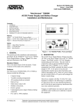
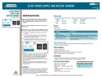
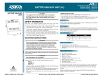
61175043L3-5A
Issue 1, January 2004
CLEI Code: SIMPAADA_
CLEI Code: SIMPAAGA_
AC/DC Power Supply and Battery Charger
Installation and Maintenance
CONTENTS
1. GENERAL ...................................................................
2. DESCRIPTION............................................................
3. INSTALLATION.........................................................
4. BATTERY BACKUP OPERATION ..........................
5. COMPLIANCE CODES..............................................
6. MAINTENANCE ........................................................
7. WARRANTY AND CUSTOMER SERVICE ............
1
1
2
4
5
5
5
FIGURES
Figure 1. AC/DC Power Supply and Battery Charger.......1
Figure 2. Cable for OPTI-3, MX2810, and NIU3 .............3
Figure 3. Cable for the MX2800........................................4
TABLES
Table 1.
Table 2.
Table 3.
LED Indication ................................................. 2
Wiring (OPTI-3, MX2810, NIU3) ................... 3
Alarm Relay Operation .................................... 4
Figure 1. AC/DC Power Supply and Battery Charger
1. GENERAL
This practice provides installation and maintenance procedures for the ADTRAN ™ AC/DC Power Supply and Battery
Charger (PS/BC). Figure 1 is a front and back illustration of
the PS/BC.
Revision History
This is the initial release of this document. Future revisions
will be made in this subsection.
Features
Features of the PS/BC, P/N 1175043L3, include the
following:
•
•
•
•
•
•
•
•
•
•
Compact design.
Versatile mounting arrangements.
All mounting hardware included.
Built-in fuse.
Multi-feature status LED.
Modular connections.
Positive ground.
Uninterrupted power output (if battery backup
connected).
FCC and UL 60950 compliant.
Complies with GR-1089-CORE and GR-63-CORE.
2. DESCRIPTION
The AC/DC PS/BC provides -54 VDC to the Power Supply
unit in various supported product systems. The PS/BC
receives 115 VAC through a standard plug and wall socket.
Some of the more common supported ADTRAN systems
include:
•
Total Access 750/850
•
Total Access OPTI-3
•
MX2800/2810
•
NIU3 (single mount housing, 3-slot shelf, 12-slot shelf)
•
Battery Backup Units
Refer to your product documentation to verify compatibility
with the PS/BC.
This device complies with part 15 of the FCC rules.
Operation is subject to the following two conditions:
(1) This device may not cause harmful interference, and
(2) This device must accept any interference that may cause
undesired operation.
Changes or modifications not expressly approved by
ADTRAN could void the user’s authority to operate this
equipment.
Fuse
A 3 Amp fuse on the back panel protects the unit from over
current. The fuse isolates the AC input from the power supply
in the event of a fault. The fuse is replaced by twisting the
61175043L3-5A
Trademarks: Any brand names and product names included in this document are
trademarks, registered trademarks, or trade names of their respective holders.
1
black cap to the left and pulling the fuse out. After the new
fuse is inserted, the cap is pushed back in and turned to the
right.
After unpacking the unit, inspect it for damage. If damage is
noted, file a claim with the carrier then notify ADTRAN
Customer Service.
Status LED
A single multi-feature LED on the front panel provides AC
operation or battery operation power status. Refer to Table 1
for indication descriptions.
MOUNTING AND WIRING INSTRUCTIONS
The following are mounting instructions for the AC/DC
PS/BC when utilized with some of the various ADTRAN
product systems. If your ADTRAN system is not listed in this
section, please refer to the documentation provided with your
ADTRAN product system for more detailed instructions.
Table 1. LED Indication
AC Power Operation
Battery Operation
Green
OK
Green
OK (charging)
Yellow
Power Fail
Yellow
Discharging
Red
Power Fail
Red
Low (< 40V)
Off
Power Fail
Off
Disconnected
Wallmounting
For the wallmount arrangement, the PS/BC is normally installed on the designated 3/4-inch or thicker plywood with
four #6 by 3/4-inch flat-head wood screws. Installation is as
follows:
1.
Determine the preferred layout and ensure the socketoutlet is located near the equipment and easily accessible.
CAUTION
This equipment MUST only be installed in a DC-C
bonding and grounding environment per Telcordia
GR-1089-CORE, Issue 3. It may not be utilized in a
DC-I (isolated) bonding and grounding environment.
2.
Ensure the unit is plumb, then mark through the four
screw holes to identify where the pilot holes will be
drilled.
3.
Using a 1/16-inch bit, drill pilot holes at the marked
locations.
SAFETY INFORMATION
When using your telephone equipment, please follow these
basic safety precautions to reduce the risk of fire, electrical
shock, or personal injury:
4.
Mount the unit using the pan-head screws.
5.
Route and connect all cabling to the appropriate device.
Use cable tie-downs as needed.
6.
Connect the ground stud using the most direct route to a
known equipment ground source.
3. INSTALLATION
1.
2.
Do not use this product near water, such as a bathtub,
wash bowl, kitchen sink, laundry tub, in a wet basement,
or near a swimming pool.
Avoid using a telephone (other than a cordless-type)
during an electrical storm. There is a remote risk of
shock from lightning.
3.
Do not use the telephone to report a gas leak in the
vicinity of the leak.
4.
Use only the power cord, power supply, and/or batteries
indicated in the manual. Do not dispose of batteries in a
fire; they may explode. Check with local codes for special disposal instructions.
ELECTROSTATIC INSTRUCTIONS
Total Access 750/850
Mounting
Mount the power supply on the left side of the Total
Access 750/850 shelf (next to the battery cover hinge)
for battery backup installations (P/N 1175044L2 and
1175044L4)
Position the Total Access PSU (power cords oriented downward) and align all four holes (on the tabs at the corner of the
Total Access PSU) with the four available machined holes on
either side of the Total Access 750/850. Use four #6 3/8-inch
machine screws (provided) to secure the Total Access PSU.
Alternately, the Total Access PSU can be mounted to a backboard with four #6 3/4-inch wood screws (not supplied).
C A U T I O N !
Wiring
SUBJECT TO ELECTROSTATIC DAMAGE
OR DECREASE IN RELIABILITY.
HANDLING PRECAUTIONS REQUIRED.
CAUTION
Electronic equipment can be damaged by static
electrical discharge. Before handling equipment, wear
an antistatic discharge wrist strap to prevent damage
to electronic components. Place equipment in
antistatic packing material when transporting or
storing. When working on equipment, always place
them on an approved antistatic mat that is
electronically grounded.
2
Before beginning the wiring connection, verify that the
Total Access 750/850 and the AC/DC Power Supply
and Battery Charger are properly grounded with the
required supplemental ground.
Power should be the last connection made during
installation.
The Total Access PSU has two cords (AC plug and 4 position
modular adapter). Insert the Total Access PSU modular
Issue 1, January 2004
61175043L3-5A
adapter into the receptacle provided on the back of the Total
Access 750/850 and plug the AC plug into the AC power
source.
Total Access OPTI-3
Mounting
An additional cable (ADTRAN P/N 1200657L10) is
required for connecting the PS/BC to Total Access
OPTI-3 systems.
Rackmounted Systems
Use a mounting bracket and secure the Total Access PSU
to the rack (19” bracket–P/N 1175050L1, 23” bracket–
P/N 1175051L1). Orient the Total Access PSU with the
cables facing away from the center and secure it with
four #6 3/8-inch machine screws. A single bracket
mounts up to 4 Total Access PSUs. Alternately, mount
the Total Access PSU directly to the rack (or a
backboard) using two or more of the mounting tabs.
Wallmounted Systems
Position the Total Access PSU (power cords oriented
downward) and align the outer two holes (on the tabs at
the corner of the Total Access PSU) with the two
available machined holes on either side of the Total
Access OPTI-3. Use two #6 3/8-inch machine screws
(provided) to secure the Total Access PSU.
Wiring
The Total Access PSU (when ordered for use with these
systems) is shipped with an adapter cable (ADTRAN
P/N 1200657L10) that has a molded modular connector on
one end and three ring type terminals on the other (see
Figure 2).
MX2810 and NIU3 Systems
Mounting
An additional cable (ADTRAN P/N 1200657L10) is
required for connecting the PS/BC to MX2810 and
NIU3 systems.
Rackmounted Systems
Use a mounting bracket and secure the Total Access PSU
to the rack (19” bracket–P/N 1175050L1, 23” bracket–
P/N 1175051L1). Orient the Total Access PSU with the
cables facing away from the center and secure it with
four #6 3/8-inch machine screws. A single bracket
mounts up to 4 Total Access PSUs. Alternately, mount
the Total Access PSU directly to the rack (or a
backboard) using two or more of the mounting tabs.
Wiring
The Total Access PSU (when ordered for use with these
systems) is shipped with an adapter cable (ADTRAN
P/N 1200657L10) that has a molded modular connector on
one end and three ring type terminals on the other (see
Figure 2).
The Total Access PSU powers a single bus (select either A or
B). Connect the ring-type terminals to the respective terminals on the rear of the chassis using the screws provided. Use
the wiring conventions in Table 2.
Connect the DC wiring harness of the Total Access PSU to
the adapter using the modular connectors and plug the AC
plug into the AC power source.
MX2800
Mounting
An additional cable (ADTRAN P/N 1200657L2) is
required for connecting the PS/BC to MX2800
systems.
Figure 2. Cable for OPTI-3, MX2810, and NIU3
The Total Access PSU powers a single bus (select either A or
B). Connect the ring-type terminals to the respective terminals on the rear of the chassis using the screws provided. Use
the following wiring conventions:
RED
-48VA or PWR
BLACK
RET
GREEN
Ground Terminal
Table 2. Wiring (OPTI-3, MX2810, NIU3)
Rackmounted Systems
Use a mounting bracket and secure the Total Access PSU
to the rack (19” bracket–P/N 1175050L1, 23” bracket–
P/N 1175051L1). Orient the Total Access PSU with the
cables facing away from the center and secure it with
four #6 3/8-inch machine screws. A single bracket
mounts up to 4 Total Access PSUs. Alternately, mount
the Total Access PSU directly to the rack (or a
backboard) using two or more of the mounting tabs.
Wiring
The Total Access PSU (when ordered for use with this
system) is shipped with an adapter cable (ADTRAN
Connect the DC wiring harness of the Total Access PSU to
the adapter using the modular connectors and plug the AC
plug into the AC power source.
61175043L3-5A
Issue 1, January 2004
3
P/N 1200657L2) that has a molded modular connector on one
end and four soldered wire tips on the other (see Figure 3).
“ground wire” in a customer equipment room. 18 AWG or
larger ground wire is recommended.
4. BATTERY BACKUP OPERATION
The following information is applicable when using the
PS/BC with any available ADTRAN BBU.
Alarm and Battery Disconnect Relays
Two relays support Power Supply operation:
Figure 3. Cable for the MX2800
Connect the soldered ends of the wires to the modular connector that fits into the chosen power bus using a small slotted
screwdriver. (The power buses are labeled A and B on the
rear of the chassis.) Use the following wiring conventions
(holding the connector as it will be inserted in the chassis):
Left
Right
WHITE
Battery Backup Alarm Wire
RED
Negative Terminal Wire
BLACK
Positive (RET) Wire
GREEN
Ground Terminal Wire
Secure the ends of the wires and plug the connector into the
chassis on the desired power bus (A or B). Connect the other
end to the DC wiring harness of the PSU wiring harness and
plug the AC plug into the AC power source.
•
•
Alarm relay
Battery disconnect relay
Alarm Relay and Alarm Signal
The Alarm relay is provided for customer use. In normal operation the contact alarm relay is open. If an AC power failure
occurs and the unit defaults to the battery backup, the relay
will cycle open.closed once per second (that is one second
open then one second closed). The tolerance on this cycle
time is 25 percent.
This indicates the battery is discharging in support of the
load. If battery voltage decreases to 45 V the relay stays
closed to indicate the battery is becoming depleted. The relay
will open automatically when normal AC voltage is restored.
Table 3 summarizes the alarm relay operation.
Table 3. Alarm Relay Operation
Battery Backup Units
Condition
Mounting
When using the PS/BC in conjunction with available
ADTRAN Battery Backup Units (BBUs), one of the
following mounting options should be used:
•
•
•
Wallmounting the PS/BC (refer to Wallmounting on
page 2).
Mounting the PS/BC to the product chassis containing
the DC power supply.
Mounting the PS/C to the BBU.
Refer to your specific ADTRAN product system
documentation to determine the optimal mounting solution
for your system.
GROUNDING INSTRUCTIONS
For complete details on product grounding requirements, refer to the Network Turnup Procedure in your product System
Manual.
GR-1089-CORE Requirement
An equipment grounding conductor that is not smaller
in size than the ungrounded branch-circuit supply
conductor is to be installed as part of the circuit that
supplies the product or system.
The ground connector on the PS/BC provides an additional
ground reference (the third prong of the AC plug is also
grounded) and may be connected to the “ground bus” or
4
Alarm Relay
Normal
Open
AC Power Failure/Battery
Backup engaged
Cycles open/closed
once per second
Battery voltage is less than
40V
Stays closed
An alarm signal that cycles synchronously with the alarm
relay is provided on the output cable. This signal, which is
open during normal operation, cycles between open and
ground during battery backup (as described for the alarm
relay), and is ground when the battery voltage falls below
45V.
Battery Fail Alarm
For battery backup systems that employ the optional Battery
Test Assembly an alarm signal is provided to the PS/BC that
indicates a failed battery (in need of immediate replacement).
This signal is passed to the Alarm Relay and Output Alarm
Signal. When a failed battery is detected, it is indicated by the
Alarm Relay cycling open for 450 ms, then closed for 450 ms.
Battery failure is also indicated by the output alarm signal
cycling open to ground at the same rate.
Battery Disconnect Relay
The battery disconnect relay disconnects the battery pack
from the system if the battery voltage falls below 40 VDC.
This feature prevents damage tot he batteries. The batteries
Issue 1, January 2004
61175043L3-5A
will be recharged when normal AC voltage is restored and the
relay will close when the battery voltage exceeds 40V.
Certain alarm features on the power supply are still powered
by the battery after the disconnect relay is opened. These
features slowly drain the battery. If it is known that AC power
will be unavailable for an extended periods (greater than a
week), ADTRAN recommends that the battery be
disconnected from the power supply to prevent overdischarge.
5. COMPLIANCE CODES
Code
Input
Output
IC
F
C
TC
—
—
PC
R
—
6. MAINTENANCE
The AC/DC Power Supply and Battery Charger does not require routing maintenance for design operation.
ADTRAN does not recommend that repairs be attempted in
the field. Repair services are obtained by returning the defective unit to ADTRAN Customer Service.
7. WARRANTY AND CUSTOMER SERVICE
All Total Access Battery Backup systems have a 10 year warranty coverage on the product. This includes cables, housings, PCBs, and any other ADTRAN-built components
(excluding lead acid batteries).
ADTRAN will repair and return this product within 10 years
from the date of the shipment if it does not meet its published
specifications or fails while in service (see ADTRAN Equipment Warranty, Repair, and Return Policy and Procedure,
document 60000087-10A).
For service, CAPS requests, or further information, contact
one of the following numbers:
ADTRAN Sales
Pricing and Availability
(800) 827-0807
ADTRAN Technical Support
Pre sales Applications/Post-sale Technical Assistance
(888) 4-ADTRAN
Standard hours: Monday-Friday, 7 a.m.-7 p.m. CST
Emergency hours: 7 days/week, 24 hours/day
ADTRAN Repair/CAPS
Return for repair/upgrade
(256) 963-8722
Repair and Return Address
ADTRAN, Inc.
CAPS
901 Explorer Boulevard
Huntsville, Alabama 35806-2807
61175043L3-5A
Issue 1, January 2004
5
6
Issue 1, January 2004
61175043L3-5A