1
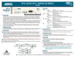
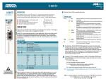
®
Total Access Rackmount 6-Amp Power
Supply Battery Charger
Installation and Maintenance Practice
Document Number: 61180043L2-5D
CLEI: VAPUKT0C_ _
June 2005
Total Access Rackmount 6-Amp Power Supply Battery Charger Installation and Maintenance Practice
Trademarks
Front Matter
Any brand names and product names included in this manual are trademarks, registered
trademarks, or trade names of their respective holders.
To the Holder of the Manual
The contents of this publication are current as of the date of publication. ADTRAN® reserves
the right to change the contents without prior notice.
In no event will ADTRAN be liable for any special, incidental, or consequential damages or
for commercial losses even if ADTRAN has been advised thereof as a result of issue of this
publication.
®
901 Explorer Boulevard
P.O. Box 140000
Huntsville, AL 35814-4000
(256) 963-8000
©2005 ADTRAN, Inc.
All Rights Reserved.
Printed in U.S.A.
ii
61180043L2-5D
Revision History
Revision
Date
D
June 2005
Description
Updated to remove Dual PS/BC Jumper Cable. Document format
updated with revision D.
Conventions
The following typographical conventions are used in this document:
This font indicates a cross-reference link. First-time references to tables and figures are
shown in this font.
This font indicates screen menus, fields, and parameters.
THIS FONT indicates keyboard keys (ENTER, ESC, ALT). Keys that are to be pressed simultaneously are shown with a plus sign (ALT+X indicates that the ALT key and X key should be
pressed at the same time).
This font indicates references to other documentation and is also used for emphasis.
This font indicates on-screen messages and prompts.
This font indicates text to be typed exactly as shown.
This font indicates silkscreen labels or other system label items.
This font is used for strong emphasis.
NOTE
Notes inform the user of additional but essential information or
features.
CAUTION
Cautions inform the user of potential damage, malfunction, or disruption to equipment, software, or environment.
WARNING
Warnings inform the user of potential bodily pain, injury, or death.
61180043L2-5D
iii
Total Access Rackmount 6-Amp Power Supply Battery Charger Installation and Maintenance Practice
Training
ADTRAN offers training courses on our products. These courses include overviews on product
features and functions while covering applications of ADTRAN’s product lines. ADTRAN
provides a variety of training options, including customized training and courses taught at our
facilities or at customer sites. For more information about training, please contact us.
Training Phone:
800-615-1176, ext. 7500
Training Fax:
256-963-6700
Training Email:
[email protected]
iv
61180043L2-5D
Contents
General . . . . . . . . . . . . . . . . . . . . . . . . . . . . . . . . . . . . . . . . . . . . . . . . . . . . . . . . . . . . . . . . . . . . . . . . . . . . . . . . . . 1
Features . . . . . . . . . . . . . . . . . . . . . . . . . . . . . . . . . . . . . . . . . . . . . . . . . . . . . . . . . . . . . . . . . . . . . . . . . . . . . . 1
Document Review . . . . . . . . . . . . . . . . . . . . . . . . . . . . . . . . . . . . . . . . . . . . . . . . . . . . . . . . . . . . . . . . . . . . . . 2
Description . . . . . . . . . . . . . . . . . . . . . . . . . . . . . . . . . . . . . . . . . . . . . . . . . . . . . . . . . . . . . . . . . . . . . . . . . . . . . . .
Single or Dual Battery . . . . . . . . . . . . . . . . . . . . . . . . . . . . . . . . . . . . . . . . . . . . . . . . . . . . . . . . . . . . . . . . . . . .
PS/BC Mounting Location . . . . . . . . . . . . . . . . . . . . . . . . . . . . . . . . . . . . . . . . . . . . . . . . . . . . . . . . . . . . . . . .
Battery Disconnect Protection Circuit . . . . . . . . . . . . . . . . . . . . . . . . . . . . . . . . . . . . . . . . . . . . . . . . . . . . . . . .
DC Over Voltage Protection . . . . . . . . . . . . . . . . . . . . . . . . . . . . . . . . . . . . . . . . . . . . . . . . . . . . . . . . . . . . . . .
Alarm Relays . . . . . . . . . . . . . . . . . . . . . . . . . . . . . . . . . . . . . . . . . . . . . . . . . . . . . . . . . . . . . . . . . . . . . . . . . .
Fuse . . . . . . . . . . . . . . . . . . . . . . . . . . . . . . . . . . . . . . . . . . . . . . . . . . . . . . . . . . . . . . . . . . . . . . . . . . . . . . . . .
LED Indication . . . . . . . . . . . . . . . . . . . . . . . . . . . . . . . . . . . . . . . . . . . . . . . . . . . . . . . . . . . . . . . . . . . . . . . . .
Compliance . . . . . . . . . . . . . . . . . . . . . . . . . . . . . . . . . . . . . . . . . . . . . . . . . . . . . . . . . . . . . . . . . . . . . . . . . . . .
2
2
2
3
3
3
3
4
4
Installation . . . . . . . . . . . . . . . . . . . . . . . . . . . . . . . . . . . . . . . . . . . . . . . . . . . . . . . . . . . . . . . . . . . . . . . . . . . . . . .
Shipping Contents . . . . . . . . . . . . . . . . . . . . . . . . . . . . . . . . . . . . . . . . . . . . . . . . . . . . . . . . . . . . . . . . . . . . . .
Mounting the PS/BC . . . . . . . . . . . . . . . . . . . . . . . . . . . . . . . . . . . . . . . . . . . . . . . . . . . . . . . . . . . . . . . . . . . . .
Alternate Mounting . . . . . . . . . . . . . . . . . . . . . . . . . . . . . . . . . . . . . . . . . . . . . . . . . . . . . . . . . . . . . . . . . . . . . .
Provisioning . . . . . . . . . . . . . . . . . . . . . . . . . . . . . . . . . . . . . . . . . . . . . . . . . . . . . . . . . . . . . . . . . . . . . . . . . . .
5
5
6
7
7
Wiring Descriptions . . . . . . . . . . . . . . . . . . . . . . . . . . . . . . . . . . . . . . . . . . . . . . . . . . . . . . . . . . . . . . . . . . . . . . . .
Ground . . . . . . . . . . . . . . . . . . . . . . . . . . . . . . . . . . . . . . . . . . . . . . . . . . . . . . . . . . . . . . . . . . . . . . . . . . . . . . .
120 VAC Power Input . . . . . . . . . . . . . . . . . . . . . . . . . . . . . . . . . . . . . . . . . . . . . . . . . . . . . . . . . . . . . . . . . . . .
DC Power Output . . . . . . . . . . . . . . . . . . . . . . . . . . . . . . . . . . . . . . . . . . . . . . . . . . . . . . . . . . . . . . . . . . . . . . .
PS/BC to Battery Configurations . . . . . . . . . . . . . . . . . . . . . . . . . . . . . . . . . . . . . . . . . . . . . . . . . . . . . . . . . . .
Battery Charge/Discharge . . . . . . . . . . . . . . . . . . . . . . . . . . . . . . . . . . . . . . . . . . . . . . . . . . . . . . . . . . . . . . . .
Alarm Wiring . . . . . . . . . . . . . . . . . . . . . . . . . . . . . . . . . . . . . . . . . . . . . . . . . . . . . . . . . . . . . . . . . . . . . . . . . . .
7
7
7
8
8
9
9
Operation . . . . . . . . . . . . . . . . . . . . . . . . . . . . . . . . . . . . . . . . . . . . . . . . . . . . . . . . . . . . . . . . . . . . . . . . . . . . . . . . 9
Maintenance . . . . . . . . . . . . . . . . . . . . . . . . . . . . . . . . . . . . . . . . . . . . . . . . . . . . . . . . . . . . . . . . . . . . . . . . . . . . . . 9
Fuse . . . . . . . . . . . . . . . . . . . . . . . . . . . . . . . . . . . . . . . . . . . . . . . . . . . . . . . . . . . . . . . . . . . . . . . . . . . . . . . . . 9
Specifications. . . . . . . . . . . . . . . . . . . . . . . . . . . . . . . . . . . . . . . . . . . . . . . . . . . . . . . . . . . . . . . . . . . . . . . . . . . . 10
Appendix A
Warranty . . . . . . . . . . . . . . . . . . . . . . . . . . . . . . . . . . . . . . . . . . . . . . . . . . . . . . . . . . . . . . . . . . . . . . . A-1
Warranty and Customer Service . . . . . . . . . . . . . . . . . . . . . . . . . . . . . . . . . . . . . . . . . . . . . . . . . . . . . . . .
ADTRAN Sales . . . . . . . . . . . . . . . . . . . . . . . . . . . . . . . . . . . . . . . . . . . . . . . . . . . . . . . . . . . . . . . . . . .
ADTRAN Technical Support . . . . . . . . . . . . . . . . . . . . . . . . . . . . . . . . . . . . . . . . . . . . . . . . . . . . . . . . .
ADTRAN Repair/CAPS . . . . . . . . . . . . . . . . . . . . . . . . . . . . . . . . . . . . . . . . . . . . . . . . . . . . . . . . . . . . .
Repair and Return Address . . . . . . . . . . . . . . . . . . . . . . . . . . . . . . . . . . . . . . . . . . . . . . . . . . . . . . . . . .
61180043L2-5D
A-1
A-1
A-1
A-1
A-1
v
Total Access Rackmount 6-Amp Power Supply Battery Charger Installation and Maintenance Practice
Figures
Figure 1.
Figure 2.
Figure 3.
Total Access PS/BC . . . . . . . . . . . . . . . . . . . . . . . . . . . . . . . . . . . . . . . . . . . . . . . . . . . . . . 1
PS/BC Mounted On Battery Pack . . . . . . . . . . . . . . . . . . . . . . . . . . . . . . . . . . . . . . . . . . . 6
Wiring Block Diagrams . . . . . . . . . . . . . . . . . . . . . . . . . . . . . . . . . . . . . . . . . . . . . . . . . . . . 8
Tables
Table 1.
Table 2.
Table 3.
vi
LED Descriptions . . . . . . . . . . . . . . . . . . . . . . . . . . . . . . . . . . . . . . . . . . . . . . . . . . . . . . . . 4
Power Factor and Efficiency . . . . . . . . . . . . . . . . . . . . . . . . . . . . . . . . . . . . . . . . . . . . . . 10
PS/BC Specifications . . . . . . . . . . . . . . . . . . . . . . . . . . . . . . . . . . . . . . . . . . . . . . . . . . . . 10
61180043L2-5D
Total Access Rackmount 6-Amp Power
Supply Battery Charger
GENERAL
US
E
F
This practice is an installation and maintenance guide for the ADTRAN® Total Access®
Rackmount 6-Amp Power Supply Battery Charger (PS/BC). Figure 1 illustrates the PS/BC
(P/N 1180043L2) right and left side panels.
Figure 1. Total Access PS/BC
Features
The Total Access PS/BC features include the following:
• –54 VDC at 6-amps output for multiple use
• Modular connections for two backup battery packs
• Modular power output connection
• LED status for VAC, VDC, and battery charging
• Full battery recharge in less than eight hours
• Two PS/BC configuration options available
61180043L2-5D
1
Total Access Rackmount 6-Amp Power Supply Battery Charger Installation and Maintenance Practice
• Fuse protection
• Positive ground
• Battery Pack mounting hardware included
• Completely automatic operation
• Multiple protection features
• Uninterrupted power output if backup battery connected
• Meets NEBS Level 3 (all requirements of GR-63-CORE and GR-1089-CORE)
• FCC and UL 60950 compliant
Document Review
This document contains important pre-installation information. Craft personnel should review
the entire document as part of installation planning.
DESCRIPTION
The PS/BC rectifier is part of the Total Access Rackmount AC Power Supply/Backup Battery
System (APS/BBS). The unit is designed to work in conjunction with one or two ADTRAN
backup battery packs (P/N 1175044L1).
Originally designed for the Total Access 1500 system, the PS/BC can be used in any application using 120 VAC input, and requiring up to –54 VDC, 6-amps output.
In the Total Access 1500 configuration, the rectifier performs AC to DC conversion and when
used with the dual battery provides up to eight hours of backup power for a fully populated
Total Access 1500 bank (96 FXS circuits) with up to 50 percent off-hook circuits at any one
time.
For general use, the rectifier receives AC power from a standard 120 VAC wall outlet and
converts this to –54 VDC, 6-amp output to the designated load plus recharging the single or
dual battery, or maintaining battery at peak charge. Each battery has four series connected
12 volt rechargeable cells.
Single or Dual Battery
Each battery string is rated for 3 amps of current and 7 amp-hours of capacity. Dual batteries
are required if the load exceeds these ratings during AC power failure (backup battery mode).
PS/BC Mounting Location
The PS/BC normally mounts to the associated battery pack. The unit can also mount to a
special bracket within a cabinet, or mount external to a cabinet against a wall.
2
61180043L2-5D
Description
Battery Disconnect Protection Circuit
During battery operation a protection circuit disconnects battery from the main output when
battery voltage drops below 39 VDC, preventing over discharge. When AC returns, the main
output provides regulated –54 VDC, batteries recharge, and the system returns to normal.
Refer to “LED Indication”.
After the protection circuit initiates, the LEDs remain on (red), continuing to slowly drain the
battery. When battery voltage drops to 35 VDC, all load is removed from the battery. If AC
power will not be available for an extended period (several days), disconnect the battery to
prevent unnecessary discharge.
DC Over Voltage Protection
The PS/BC has a protection circuit that disables the rectifier to protect the load from a high
output voltage caused by rectifier failure. The backup battery or redundant PS/BC supports
the load in this instance. The over voltage event can permanently disable the PS/BC. Confirm
this by performing the following procedure:
1. Disconnect the PS/BC from the AC source.
2. Wait 30 minutes minimum.
3. After 30 minutes plug back into the AC source.
4. If the unit has recovered, the AC FAIL/UNIT FAIL/OVERLOAD LED will turn on green and the
unit returns to service. If the LED does not turn on green, replace the PS/BC.
Alarm Relays
There are two uncommitted alarm relays associated with PS/BC operation:
• AC Fail (ACF): Alarms if AC fails, the rectifier overloads, or the rectifier fails
• Battery Low Voltage (BV): Alarms if either or both battery voltage drops below 42 VDC
Fuse
A standard 5×20 mm 5-amp fuse adjacent to the AC power cord protects AC power feed
overload in case of rectifier failure.
61180043L2-5D
3
Total Access Rackmount 6-Amp Power Supply Battery Charger Installation and Maintenance Practice
LED Indication
A set of three PS/BC multi color LEDs provide status for AC, DC, and battery charge conditions. See Table 1 for LED descriptions. Descriptions are also labeled on the PS/BC.
Table 1. LED Descriptions
LED
AC FAIL/UNIT FAIL/OVERLOAD
Color
Green
Red
BATTERY VOLTAGE
Normal 120 VAC operation
AC fail or rectifier overload or fail
Green
Battery 1 and Battery 2 greater than 42 VDC
Yellow
Battery 1 or Battery 2 less than 42 VDC
Red
CHARGING STATUS
Description
Battery 1 and Battery 2 less than 40 VDC
Green
Battery 1 and Battery 2 charged or recharging
Yellow
Battery 1 or Battery 2 discharging
Red
All LEDs
Off
Battery 1 and Battery 2 fully discharged
AC lost, Battery less than 35 VDC
Note: Descriptions are the same for a single battery.
Compliance
This device complies with Part 15 of the FCC rules. Operation is subject to the following two
conditions:
1. This device may not cause harmful interference.
2. This device must accept any interference received, including interference that may cause
undesired operation.
Changes or modifications not expressly approved by ADTRAN could void the user’s authority
to operate this equipment.
4
61180043L2-5D
Installation
INSTALLATION
C A U T I O N !
SUBJECT TO ELECTROSTATIC DAMAGE
OR DECREASE IN RELIABILITY.
HANDLING PRECAUTIONS REQUIRED.
After unpacking the Total Access PS/BC, inspect it for damage. If damage has occurred, file a
claim with the carrier, then contact ADTRAN Customer Service. Refer to “Appendix A,
Warranty” for further information. If possible, keep the original shipping container for
returning the PS/BC for repair or for verification of shipping damage.
CAUTION
Electronic modules can be damaged by ESD. When handling modules, wear an antistatic discharge wrist strap to prevent damage to
electronic components. Place modules in antistatic packing material when transporting or storing. When working on modules,
always place them on an approved antistatic mat that is electrically
grounded.
Shipping Contents
The contents include the following items:
• Rackmount 6-Amp Power Supply Battery Charger
• Rackmount 6-Amp Power Supply Battery Charger Installation and Maintenance Practice
• Appropriate wiring:
– PS/BC to AC source (hardwired)
– PS/BC to load
– PS/BC alarm output
• Battery Pack mounting hardware
Separately purchased Rack Mounting Kits for the PS/BC are available for the following racks:
• 19-inch (P/N 1175050L1)
• 23-inch (P/N 1175051L1)
61180043L2-5D
5
Total Access Rackmount 6-Amp Power Supply Battery Charger Installation and Maintenance Practice
Mounting the PS/BC
The PS/BC housing occupies a nominal area 15.35 inches (with mounting tabs) wide by 3.45
inches high and is designed so the four mounting tab screw holes align to threaded screw
holes on the ADTRAN battery pack housing. This procedure assumes that the battery pack is
mounted in the designated 19-inch or 23-inch rack. Hardware for mounting the PS/BC to the
battery pack is included. To mount the PS/BC, perform the following steps:
1. Ensure a 120 VAC wall outlet is within reach of the PS/BC 10-foot power cord.
2. Determine the most convenient direction to view the status LEDs and position the PS/BC
accordingly.
3. Align the mounting tabs to the threaded mounting holes on the battery pack.
4. Using the included “sems” screws with star washer, mount the PS/BC to the battery pack.
Tighten fasteners firmly.
See Figure 2 for a representative example of the PS/BC mounted to the battery.
4L1 KU
504 BAC
117 ERY
TT
BA
P
/8"
: G3
INGEDIN .
RNEXCE TRIES
WNAGTHSRE BAT
3/8
: DING S.
INGCEE TRIE
RN S EX BAT
WLEANGTNHCTURE
W PU
RE AY
SC M
LE TU
W NC
RE PU
SC MAY
"
4L1 UP
504 CK
117 Y BA
ER
T
T
BA
CAUTION:
FOR CONTINUED PROTECTION AGAINST
RISK OF FIRE, REPLACE ONLY WITH THE
SAME TYPE AND RATING OF FUSE.
US
FUSE: 12A/125V
F
E
1180043L2
Figure 2. PS/BC Mounted On Battery Pack
6
61180043L2-5D
Wiring Descriptions
Alternate Mounting
Two alternate mounting methods include mounting directly to a wall using customer supplied
wood screws, or to a 16-gauge steel bracket (P/N 3265555) that mounts in the cabinet.
Bracket mount location is normally at the battery position when batteries are mounted
external to the cabinet. The bracket has threaded mounting holes that align to the PS/BC
mounting tabs. The PS/BC can be mounted to either side of the bracket, or two PS/BCs can
be mounted, one on each side. Openings in the bracket allow for wire management. Hardware
for bracket mounting is purchased from ADTRAN. When determining the alternate mounting
location, ensure supplied cabling reaches the designated termination point including dressing
and lacing.
Provisioning
Aside from various PS/BC and battery mounting and wiring configurations, there are no end
user controls, adjustments, or options associated with the PS/BC.
WIRING DESCRIPTIONS
The wiring required for the single PS/BC and dual battery configuration is included.
CAUTION
All grounds must terminate at a known ground location. Check
metal-to-metal contact on all ground connections. Do not stack or
combine grounds. Ensure ground circuit continuity.
Ground
A ground post adjacent to the PS/BC fuse is available for frame ground.
WARNING
Do not connect AC power or make battery connections until all
other connections have been made for the designated installation
and protective covers and shields have been installed.
120 VAC Power Input
AC input is through a 10-foot wire with a three prong grounded plug on the end. The line is
hardwired to the PS/BC.
NOTE
In the optional two PS/BC configuration, a fully redundant system
requires that each PS/BC have an independent AC source.
61180043L2-5D
7
Total Access Rackmount 6-Amp Power Supply Battery Charger Installation and Maintenance Practice
DC Power Output
The 4-foot long, three conductor PS/BC power output wire originates at the –54V 6A OUTPUT
modular connector and terminates at three #6 ring lugs for customer designated connection.
Wire color-code is as follows:
• Red = –54 VDC
• Black = Return
• Green = Ground
PS/BC to Battery Configurations
The basic design configuration consists of one PS/BC with two batteries. A variety of other
configurations are possible with more (or less) redundant capability, see Figure 3 for standard
configurations I and II.
A
Load
PS/BC
A
A
PS/BC
A
Configuration I, Ia, Ib
I. PS/BC, no battery.
Ia. PS/BC + 1 battery string.
Ib. PS/BC + 2 battery strings.
B
I
Batt
Ia
Batt
Ib
Load
B
II
PS/BC
B
II
Configuration II, IIa, IIb, IIc, IId
II. 2 PS/BC, no battery.
IIa. 2 PS/BC + 1 battery string.
IIb. 2 PS/BC + 2 battery strings.
IIc. 2 PS/BC + 3 battery strings.
IId. 2 PS/BC + 4 battery strings.
This configuration shows adding battery
strings alternately to PS/BC A and B.
Other wiring configurations are optional.
Batt
IIa
Batt
IIb
Batt
IIc
Batt
IId
Figure 3. Wiring Block Diagrams
These would include one or two PS/BCs, none, one, or two batteries, or some combination of
PS/BC and battery. The most reliable configuration would be two PS/BCs with two batteries
each and with independent AC sources. The two PS/BC outputs would terminate at a single
load that has primary and secondary power sharing terminals.
8
61180043L2-5D
Operation
Battery Charge/Discharge
CAUTION
To prevent battery discharge prior to system operation, do not connect the battery to the PS/BC until the AC power is connected or
imminent.
Each battery has a hardwired 6-foot battery charge/discharge wire that originates at the
battery housing and terminates at a modular connector. The PS/BC has two mating
connector ports each labeled –48V 3A INPUT. It does not matter which battery connects to
which port.
To prevent heat buildup the battery charge current is limited to 1 amp per battery. This eliminates the need for temperature compensation.
Alarm Wiring
The alarm relay output originates at a modular connector with a 6-foot wire stub. Wiring
termination of the output is customer designated. The alarm outputs: AC Fail, Battery Low
Voltage, are assigned the following wire color-codes:
• ACF = orange, orange/white
• BV = blue, blue/white
OPERATION
The PS/BC starts operation when AC or battery power is applied. During operation ambient
temperature can increase up to 50°C without affecting output. If ambient temperature
increases beyond 50°C, output must be derated. At 70°C ambient, output load is limited to 5
amps.
CAUTION
External PS/BC surfaces can become hot during operation above
50°C ambient temperature.
MAINTENANCE
The Total Access PS/BC does not require routine maintenance for normal operation.
ADTRAN does not recommend that repairs be attempted in the field. Repair services may be
obtained by returning the defective unit to ADTRAN. Refer to “Appendix A, Warranty” for
further information.
Fuse
If the fuse fails, replace with a fuse of identical type and rating.
61180043L2-5D
9
Total Access Rackmount 6-Amp Power Supply Battery Charger Installation and Maintenance Practice
SPECIFICATIONS
Power Factor specifications for the Total Access PS/BC are listed in Table 2. PS/BC specifications are listed in Table 3.
Table 2. Power Factor and Efficiency
Power Output vs. Efficiency
Power Output
Power Factor
Efficiency
Power Dissipation
50 watts
> 98%
> 81%
11 watts
150 watts
> 99%
> 89%
18 watts
325 watts
> 99%
> 91%
29 watts
Table 3. PS/BC Specifications
Specification
Description
Environmental
Operating Temperature:
Derated Operation,
Linear:
Storage Temperature:
Relative Humidity:
Max Heat Dissipation:
–40°C to 50°C
50°C to 70°C (0.05 amp/°C)
–40°C to 85°C
95 percent noncondensing
29 watts at 325 watts output
50 watts maximum during overload
Physical
Height:
3.45 inches
Width:
15.35 inches (with mounting tabs)
Depth:
2.92 inches
Weight:
5.5 pounds
Electrical
AC Input:
DC Output:
120 Volts, 3.75 amps max, 60 Hz
–54 Volts, 6 amps
Max power up to 50°C:
6 amps
Max power @ 70°C:
5 amps
Power Output:
325 watts
Compliance
NEBS:
10
Level 3+
UL:
60950
ETL:
Listed
FCC:
Part 15, Class A
61180043L2-5D
Appendix A
Warranty
WARRANTY AND CUSTOMER SERVICE
ADTRAN will replace or repair this product within the warranty period if it does not meet its
published specifications or fails while in service. Warranty information can be found at
www.adtran.com/warranty.
Refer to the following subsections for sales, support, Customer and Product Service (CAPS)
requests, or further information.
ADTRAN Sales
Pricing/Availability:
800-827-0807
ADTRAN Technical Support
Pre-Sales Applications/Post-Sales Technical Assistance:
800-726-8663
Standard hours: Monday - Friday, 7 a.m. - 7 p.m. CST
Emergency hours: 7 days/week, 24 hours/day
ADTRAN Repair/CAPS
Return for Repair/Upgrade:
(256) 963-8722
Repair and Return Address
Contact CAPS prior to returning equipment to ADTRAN.
ADTRAN, Inc.
CAPS Department
901 Explorer Boulevard
Huntsville, Alabama 35806-2807
61180043L2-5D
A-1
®
Carrier Networks Division
901 Explorer Blvd.
Huntsville, AL 35806