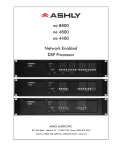
1
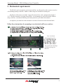
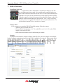
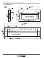
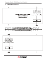
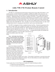
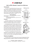
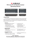
FR-8 and FR-16 Remote Control
Operating Manual
Introduction
PRELIMINARY
The FR-8 and FR-16 are Ethernet-based remote control units for Ashly products, currently including the ne24.24M, NE two-channel amplifiers, NE multichannel power amplifiers, ne8800/4800
DSP processors, and all Pema amplifiers. The FR-8 controls up to eight assigned channels, and the
FR-16 controls up to 16 assigned channels. Each fader can be assigned to control input/output DSP
gain tools, or control an output mixer level. The master fader provides an overall level control for all
faders, and can be disabled in software. Buttons above each fader provide mute control, and can also
be configured to indicate signal level. Each unit is powered using IEEE 802.3af Power over Ethernet
(PoE), or by an external powers supply if PoE is unavailable. A clear mylar window is provided next
to each fader and switch to allow insertion of user defined labels. The units are designed to mount to
a standard US electrical wall box , can be mounted to a flat surface with a cutout, or can be used as a
desktop device.
Read this manual to fully understand all network, mechanical, firmware, and software requirements, as well as security and hardware lockout features available on the FR-8/16.
When the FR-8/16 is first powered on, it attempts to communicate with all devices it has been
configured to control, which may take several seconds. Once found, the FR-8/16 will transmit the
current state of its faders and mute buttons. Subsequent changes to the faders and mute buttons will
be tracked by the assigned device. It’s a good idea to ensure that all faders are either in the correct
position or fully down when connecting a FR-8/16 to the network. This ensures that unexpected
loud signals levels won’t reach speakers when the FR-8/16 first announces fader positions to connected devices.
ASHLY AUDIO INC.
847 Holt Road Webster, NY 14580-9103 Phone: (585) 872-0010
Toll-Free: (800) 828-6308 Fax: (585) 872-0739 www.ashly.com
Operating Manual - FR-8/16 Remote Level Controller
1. Network requirements
Ethernet communication with this device is made by wiring
it with standard Cat-5 cable terminated with an RJ-45 connector
through an Ethernet network router, switch, hub, or patch panel
to a PC running Protea NE Software v5.10 or higher. Maximum
cable distance is 100 meters (328 ft) from the nearest router, hub,
or switch. Ashly networked devices will auto detect their Ethernet network connection, and adapt to either a straight through pin to pin, or crossover Ethernet cable.
Note that the push release tab on the back panel connector (as shown) is meant only for XLR type RJ-45
connectors. Non-XLR type RJ-45 connectors have their own release tab built in.
IP Address - There is no need to assign an IP address to FR-8/16 used with a network router. The
router or Link Local Addressing will assign IP addresses to each product automatically. When a router
is not available, most current NE products and remotes have the capability to assign their own IP address
based on Link Local Addressing. This allows the device to operate without the need to set up static IP
address. If the only option is to use an Ethernet switch instead of a router, and communications problems
remain which cannot be solved with the use of the link local standard, each device must have a static IP
address assigned from within Protea NE software. This is done by selecting “Manual Configuration” in
the Network Properties tab of each device, where the system/network administrator must assign each
product its’ own unique static IP address, each with the appropriate sub net if applicable.
Firewalls - If Protea NE software does not detect the FR-8/16, the firewall in the host PC
should be turned off, as firewalls may block the device response to the controlling PC when network
communication is attempted. The current PC firewall status is found by clicking on the Windows
Start button, then Control Panel, then double clicking on the security shield where the firewall can
then be disabled. Once communications with the device is established, the firewall can be enabled
again, but if there continues to be communications problems then disable the firewall.
PRELIMINARY
Wi-Fi and LAN – For the initial device auto-configuration process, any secondary Wi-Fi connection should also be disabled, and the LAN (Local Area Network) connection must be enabled on
the PC. Secondary network connections may confuse the auto device discovery process. Go to the
Windows Control Panel, then Network Connections, to disable any secondary network connections.
Once communications with the device is established, secondary network connections can be enabled
again, unless a communications problem remains with the FR-8/16, in which case the secondary
network connections should remain disabled.
Connecting Device(s) - Connect an Ethernet cable with PoE (Power over Ethernet) to the FR8/16 unit. If a successful Ethernet connection has been made, a solid green LED (Link) lights up
near the device Ethernet port. If there is no green LED showing, there is either a problem with the
cable or the network source, which must be addressed before proceeding further. All RJ-45 Ethernet
ports flash green when active, so backtrack through any other cables, routers, or switches to find the
problem. The flashing yellow LED (Data) indicates that data is flowing to or from the device.
Power over Ethernet - FR-8/16 remote controllers must be phantom powered using a IEEE
802.3af Power over Ethernet (PoE) switch, hub, or in-line PoE injector. Power consumption is two
watts maximum.
2
Operating Manual - FR-8/16 Remote Level Controller
2. Mechanical requirements:
The FR-8/16 can be mounted to an electrical wall box, any flat surface with a cutout, or used as
a freestanding desktop controller. Adhesive rubber strips are included for desktop use.
The FR-16 will mount to a modular 7-gang US electrical box, with a minimum box depth of
2.25”. The FR-8 mounts to a 4-gang electrical box. For mounting to a wall or flat surface without
using a wall box, a mechanical drawing and cutout pattern are provided in this manual.
A template is provided later in this manual for creation of fader and switch function labels.
Follow these instructions for mounting to an electrical wall box or surface:
Note: Avoid static
shock disruptions to this
or other connected devices
by mounting to an earthgrounded metal wall box or
other earth grounded point.
This prevents static discharge
from flowing through the
data lines.
PRELIMINARY
3
Operating Manual - FR-8/16 Remote Level Controller
3. Software Requirements
Protea NE Software version 5.10 or greater is required for the FR-8/16. Load it to a PC from
the included CD or from the Ashly website.
4. Firmware Requirements
Ashly NE devices to be controlled by the FR8/16 have minimum firmware requirements as
well. Firmware is the embedded program that runs on Ashly NE devices. Firmware updates can be
flash programmed on all Ashly networked devices, and are available on the Ashly website. Minimum firmware revisions for Ashly NE products used with the FR-8/16 are listed below:
Ashly NE Product
Minimum Firmware Rev
ne24.24M . . . . . . . . . . . . . . . . . . . . . . V2.9
NE two channel amplifiers. . . . . . . . . V1.9
NE multichannel amplifiers . . . . . . . . V3.1
ne8800/4800/4400 dsp processor. . . . V1.9
Pema amplifiers . . . . . . . . . . . . . . . . . V2.4
See each device’s user manual for instructions on how to flash reprogram that device.
PRELIMINARY
5. FR-8/16 Firmware Update Procedure (Flash Reprogram)
To view a network installed FR-8/16’s firmware revision, click on its Network Properties tab
in Proteane software and look in the Hardware Configuration section. If a new firmware update is
available on the Ashly website, the user may download it and run the Flash Reprogram procedure
found in the FR-8/16’s Device Options menu. When the FR-8/16 is put into flash reprogram mode,
the highest channel LED turns green and Master LED turns amber. All control function is suspended
until flash reprogram is completed.
6. Protea NE Software
Network Tree - Start Protea NE Software and the
FR-8/16 should appear in the network tree in the “Ashly
Remotes” folder. From the factory, it should appear with
the name “FR-8 (or 16) Fader Remote” in green. If it
doesn’t appear, click the “Scan For Devices” button under
the network tree. All devices continuously broadcast their
availability to the software. All currently connected and active products are highlighted in green, while products which
have been formerly connected but are currently off-line or
unavailable show up in red. To clear the network tree of all unavailable (red) items, right click the
top level item (Ashly Network) and select <Clear Inactive Devices In All Groups>.
4
Operating Manual - FR-8/16 Remote Level Controller
Project Canvas - To configure the FR-8/16, double-click its icon in the network tree, which
brings up that FR-8/16’s control surface. Alternatively, drag the icon from the network tree onto the
project canvas and doubleclick it there. Drawing elements such as lines, rectangles, text, and image files can be added to the canvas to complete a visual control screen displaying all Ashly devices
under control, which is then saved as a project file. Drawing elements are found as icons above the
canvas. To add text or image files, right click over empty canvas. The saved project file contains all
devices, settings, and drawing elements shown on the project canvas.
Once an image has been placed on the canvas, it must be manually deleted if that device is no
longer available to the software. Scanning for devices does not automatically remove images which
may have been installed at one time but are now off line. To clear the canvas of all devices and
drawn elements click <File - New>.
Design Mode - Design Mode must be enabled to work with devices or drawing elements in
the project canvas. Right-click on canvas to enable Design Mode. This allows placed objects to be
moved around, while unchecking Design Mode locks objects in place and prevents the addition of
other objects or devices. Further help is available in Protea NE software by navigating through the
online help menu.
6.1 Control Surface Tab
Within the control surface tab,
there are two additional tabs at the
bottom of the frame labeled “Configuration” and “Fader Test”. The “Configuration” tab is where the FR-8/16
gets programmed. The “Fader Test”
tab shows each fader’s current position and state of the mute button, and is
useful to verify that the remote device
is working properly.
PRELIMINARY
6.1a Configuration
All programming of faders happens in the configuration tab. Each
fader is listed by number in the Device column, and can be programmed
individually to control one exclusive
NE device using the drop down menu.
Each fader can operate in one of two
exclusive modes, Mixer mode or I/O
Level Control mode. Once the targeted
device is selected and the mode is set,
a drop down list of available target device control points is shown. Changes
5
Operating Manual - FR-8/16 Remote Level Controller
for individual faders will not be written to the device until clicking the “Assign” button associated
with that fader. All changes made to all faders can be written to the target device in their entirety by
clicking “Assign All”.
Mixer Mode - In Mixer Mode, faders are assigned to the host device’s output channel
mixer, with each fader corresponding to an input source for that mixer. While any fader can be arbitrarily set to control any mixer input source, mixer mode setup is enhanced by the automatic fill-in of
increasing channel faders corresponding with increasing input sources. Once the initial fader is set,
incrementing fader numbers will be automatically assigned in order, up to the point where they run
into a fader which was previously assigned elsewhere. The host unit’s mixer will appear with red
arrows to the left of each fader, indicating current position of FR-8/16 faders assigned to that mixer.
I/O Level Control Mode - I/O Level Control mode offers individual assignment of
FR-8/16 faders to single input or output channel DSP gain controls on the host unit, whereby the FR8/16 fader works along with the gain tool (or other remote control gain tools). In the DSP gain tool
of the host unit, there will appear a green arrow to the left of the fader to indicate cumulative remote
control gain in addition to the host unit’s own DSP gain setting. The resulting numeric gain total
shown at the bottom of the fader window is the net sum of all contributing gain controls.
Options
Show Signal Level on Buttons - The switch buttons above
each fader normally glow green when active and red when muted. There
is an option in the control surface configuration window to have all fader
buttons show signal level (see color key) instead of mute status. The dBfs
(full scale) rating is used in the DSP domain, where 0dBfs is the maximum
audio level possible in the targeted device.
PRELIMINARY
Disable Master Fader - In either fader mode, the Master Fader normally controls, as
a group, the overall level of each assigned fader. The master fader can be disabled by checking the
‘Disable Master Fader” check box in the control surface configuration window.
Clear All - This button clears the settings of all faders in the configuration window. It
does not clear the “Show Signal Level on Buttons” or “Disable Master Fader” check boxes.
Assign All - This button writes all of the fader configuration changes made in software to the FR-8/16 remote device.
6.1b Fader Test Window
The Fader Test tab in the main control
panel window shows a real-time image of the
associated FR-8/16 device. Current position and
changes made to the actual device will be shown
here. There are no user controls in this window,
it is for status viewing only.
6
Operating Manual - FR-8/16 Remote Level Controller
7. Other Features
Front Panel Lock-Out
In applications where unintended or unauthorized changes to the faders or buttons must be prevented, a key switch can be connected to the two
pins on the Euroblock connector near the FR-8/16’s back panel Ethernet port.
When these two pins are left unconnected, the front panel operates normally.
When these pins are electrically connected, any physical changes on the front
panel are locked out and ignored by the software. Note: Before unlocking
the front panel, it is suggested that all faders first be placed fully down or at
predetermined marked levels to avoid excess volume.
Factory Reset
If it is necessary to restore the FR-8/16’s default settings, follow these steps:
1. Remove power from the FR-8/16.
2. Press and hold down buttons 5, 6, 7, 8 on the FR-8, or 9, 10, 11, 12 on the FR-16.
3. Apply power to the FR-8/16.
4. Release the held buttons after all the buttons glow amber.
Security
In addition to the hardware lockout available on the FR-8/16, there are multiple user/multiple
levels of software protection assignable to the FR-8/16 within the Security tab. The security data is
stored within the FR-8/16 itself, not Protea NE Software. Passwords are case sensitive. Be sure to
write down the password and store in a convenient place for future reference.
PRELIMINARY
7
Operating Manual - FR-8/16 Remote Level Controller
8. Dimensions
PRELIMINARY
8
Operating Manual - FR-8/16 Remote Level Controller
9. Panel Cutout Pattern
PRELIMINARY
9
Operating Manual - FR-8/16 Remote Level Controller
10. Function Label Template
PRELIMINARY
10
Operating Manual - FR-8/16 Remote Level Controller
11. Ashly Audio Inc. LIMITED WARRANTY (USA ONLY)
(Other countries please contact your respective distributor or dealer.)
For units purchased in the USA, warranty service for this unit shall be provided by ASHLY
AUDIO, INC. in accordance with the following warranty statement.
ASHLY AUDIO, INC. warrants to the owner of this product that it will be free from defects in
workmanship and materials for a period of FIVE years from the original-date-of-purchase. ASHLY
AUDIO INC. will without charge, repair or replace at its discretion, any defective product or component parts upon prepaid delivery of the product to the ASHLY AUDIO, INC. factory service department, accompanied with a proof of original-date-of-purchase in the form of a valid sales receipt.
This warranty gives you specific legal rights, and you may also have other rights, which vary from
state to state.
EXCLUSIONS: This warranty does not apply in the event of misuse, neglect, or as a result of
unauthorized alterations or repairs made to the product. This warranty is void if the serial number is
altered, defaced, or removed. ASHLY AUDIO, INC. reserves the right to make changes in design, or
make additions to, or improvements upon, this product without any obligation to install the same on
products previously manufactured.
Any implied warranties, which may arise under the operation of state law, shall be effective
only for FIVE years from the original-date-of-purchase of the product. ASHLY AUDIO, INC. shall
be obligated to only correct defects in the product itself. ASHLY AUDIO, INC. is not liable for any
damage or injury, which may result from, or be incidental to, or a consequence of, such defects.
Some states do not allow limitations on how long an implied warranty lasts, or the exclusion, or
limitation of incidental or consequential damages, so the above limitations or exclusions may not
apply to you.
PRELIMINARY
OBTAINING WARRANTY SERVICE:
For warranty service in the United States, please follow this procedure:
1) Return the product to ASHLY AUDIO, INC. freight prepaid, with a written statement describing the defect and application that the product is used in. ASHLY AUDIO, INC. will examine
the product and perform any necessary service, including replacement of defective parts, at no further cost to you.
2) Ship your product to:
ASHLY AUDIO, INC.
Attention: Service Department
847 Holt Road
Webster, NY 14580-9103
Ashly Audio Inc
847 Holt Rd
Webster NY 14580
585-872-0010
toll free 800-828-6308
fax 585-872-0739
www.ashly.com
© 2011 by Ashly Audio Corporation. All rights reserved worldwide.
Printed in USA 0511 R0