1
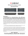
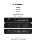
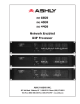
Ashly WR-5 NE Product Remote Control 1. Introduction The WR-5 is a microprocessor based remote control unit for most Ashly NE products. Compatible products currently include Pema amplifiers, ne8800 and ne4800 system processors, the ne24.24M matrix processor, and all models of the NE multichannel (four or eight channel) power amplifiers. Additional products may become available in the future. Using Protea NE software, six function select buttons and two parameter adjust buttons are available to control a limited range of assigned functions within their host product. Up to four WR-5 units can be daisy-chained and phantom powered from one NE product, and even more can be added using an in-line power supply adapter such as the Ashly RPS-18. Note: If a WR-5 is used with a NE host product, no other serial communications devices, including the Ashly RD-8C, may be used with that product. The WR-5 is designed to fit into a standard electrical wall box. Electrical connections to the host unit are made using a four conductor low gauge wire terminated with euroblock connectors. There is also a two pin jumper labelled “J6” which requires the provided female jumper to be installed in specific situations (see section 2). Note: The WR-5E is the functional equivalent to the WR-5, designed to fit into European electrical boxes. A standard decora plate (not included) can be purchased separately to cover the WR-5 electrical box and satisfy the aesthetic needs of the installation. Note: Avoid static shock disruptions to connected devices by mounting the WR-5 to an earth-grounded metal wall box, or by earth-grounding a metal decora plate. This prevents any static discharge from flowing through the data lines. Each of six buttons on the WR-5 can be programmed through Protea NE Software to engage one of the following functions (if available): preset recall, preset scroll, gain control, channel engage/mute, zone source selection, logic output active high, logic output active low, and matrix mixer, with a green LED next to each button to display active status. To the right of each button is a pocket in the mylar overlay for a paper function label to be inserted. The two other buttons are used to adjust function parameters, indicated by the LED display. FCC Compliance This device complies with part 15 of the FCC Rules for class A operation, and is subject to the following two conditions: 1. This device may not cause harmful interference. 2. This device must accept any interference received, including interference that may cause undesired operation. Operating Manual - WR-5 Remote Control for NE Products 2. Wiring a WR-5 The WR-5 uses a four conductor phantom powered serial bus to connect to its host unit or to subsequent WR-5 units. Up to four WR-5 remotes can be powered from one host unit. Ashly makes an Inline Power Booster for use in applications that require more than four WR-5 remotes. Four conductor telephone wire is suitable for all wiring, as well as CAT5, but if shielded wiring is used be sure to ground the source end of the shield. Under no circumstances should shielding be left unconnected to ground, as the added line capacitance will degrade the data signal. Wiring in Series: If more than one WR-5 is being wired in series, connect the next length of four conductor bus wire from the first WR-5’s “LINK” connector to the following WR-5 “INPUT” connector, and so on, until the last WR-5 is wired. On the last WR-5 in series wiring, and even if there is only one WR-5, install the female jumper J6 on the back of the pcb to terminate the serial data bus, and make sure all prior WR-5 units have that jumper removed. Maximum cable length for data integrity is 1,000 ft between the host unit and the first WR-5, and 1,000 ft between each subsequent WR-5. Wiring in parallel from a central location: Some installations are more suited to wiring multiple WR-5 units from one central location rather than daisy-chaining one WR-5 to the next. Using a punch down block wired to the host unit’s data connector, each WR-5 uses one four conductor cable terminated with a single euroblock connector originating from the punch down block. The +18 and Ground connections get parallel wired to each WR-5 (up to four), but the data signal still gets wired in series In the following manner: Wire the host unit’s Data Out (pin 2) to the punch down block, then out from there to the first WR-5 Data Input (J2 pin 2), out J2 pin 1 back to an isolated punch 2 Operating Manual - WR-5 Remote Control for NE Products down block connection, then back out from there to the next WR-5 data input (J2 pin 2), out J2 pin 1 of that WR-5 back to yet another isolated punch down block connection, and so on, with the last WR-5 Data Output (J2 pin 1) wired back to the host unit’s Data In connection. In this type of centralized wiring scheme, every WR-5 that returns its data signal back to the punch down block using J2 pin 1 must have its J6 jumper installed. Without the J6 jumper installed, the data input signal on J2 pin 2 is routed to J3 pin 2 for WR-5 series wiring as illustrated above. Maximum cable length for data integrity is 1,000 combined feet between any two active units. When more than four WR-5s are being used, an external DC power supply is required. The power supply must provide at least 13VDC and no more than 35VDC. In addition, each WR-5 requires 30mA of current, (or 0.03 Amperes). To determine the minimum current rating of the power supply in mA, multiply 30 times the number of WR-5 remotes to be used (Note: 1000mA = 1A). Ashly offers an Inline Power Booster called the RPS-18 that provides 24VDC and 625mA maximum current. It has common, euroblock-style terminals for easy insertion between the host data port and WR-5 Input jack. Alternatively, it can be inserted between the J3-LINK jack of any of the first four WR-5 remotes, and the J2-INPUT jack of the next WR-5 in the chain. This latter application can be useful to overcome voltage losses, caused by long cable runs to multiple remotes. In either application, do not connect the +18V pin from the host unit’s Data connector to the external supply +18V. It is possible to use the host unit’s +18V for the first four WR-5 remotes and then supplement any remaining WR-5 remotes with the inline power booster. Always connect the external power supply ground to the host unit’s Data connector ground. Cable Length - Two things to consider when running cable to the WR-5 are data integrity & power supply voltage. Active buffers (line drivers) in the WR-5 maintain data integrity, allowing up to 1,000ft (304m) of cable between devices. Thus, a maximum cable length up to 1,000ft may be used between the Remote Data Port and WR-5 remote, and another cable up to 1,000ft may be used from the WR-5 Link jack to an additional WR-5 remote, and so on. Hence each WR-5 functions as a data repeater. However, long cable runs act as resistors, which reduce the DC power supply voltage delivered to the WR-5. Each WR-5 requires a minimum of 13VDC measured across J2-INPUT jack terminals 3 & 4. It is vital to keep track of the power supply voltage drop across each successive cable run to those pins. For example, typical CAT5 (24AWG) wire has a DC resistance of 0.026 ohms per foot. Since there are two conductors, (V+ and GND), the resistance is doubled to 0.052 ohms per foot. Therefore, voltage drop across CAT5 wire can be computed as: Voltage drop = current (in Amps) * 0.052 (ohms) * cable length in feet Where current is computed at 30mA (0.03A) per WR-5. If the supply voltage at the WR-5 falls below 13VDC, the WR-5 will not power up. TIP: To minimize voltage loss over cable length, use multiple conductors for V+ and GND, (WR-5 terminals 3 & 4). For example, CAT5 wire has a total of eight 24AWG conductors. Use one pair for wiring up the two data terminals. Use three conductors in parallel for V+, and use the three remaining conductors for GND. This effectively reduces the power supply voltage drop by a factor of three. 3 Operating Manual - WR-5 Remote Control for NE Products 3. Getting Started The WR-5 comes with all function buttons set to “Off”. To program from a PC running Protea NE Software, follow these steps: 1) Connect a PC running Protea NE Software to the host NE product using a standard ethernet RJ-45 cable. 2) Connect the first WR-5 to the NE product’s data connector as shown, installing the jumper on J6 if it is the only WR-5. Upon connecting and powering up the system, the WR-5 will have a “heartbeat”, meaning an internal small green LED on the PCB will be flashing. As a WR-5 powers up, the LCD first shows the two digit firmware revision, then once communication with the host is established the WR-5 displays “- -” in the LCD window. If there is a two-digit number showing in the LCD, that means the WR-5 has been previously programmed to control a zone and that number is the gain level for that zone. In the Protea NE software window, the WR-5 will appear in an expaned menu of its host unit in the left side listing on the screen. Individual NE products and their remote control units can be dragged onto the project canvas to simulate physical rack and room installation groups, but editing each product can be done from either the product list or the canvas. Once an image has been placed on the canvas, it must be deleted by hand if that device is no longer available to the software. Scanning for devices does not automatically remove images which may have been installed at one time but are now off line. However, in the NE system menu at the left side of the screen, an offline host unit will appear in red text while an online unit appears in green. Further WR-5 help is available by opening the WR-5 device and pressing F1, or by navigating through the software Help menu. The project canvas is used to visually represent and control a fixed physical sound system installation, and can display all Ashly NE processors, amplifiers, and remotes used in that system. Lines, rectangles, text, and image files can be added to create a custom virtual control screen along with the NE products and individual control objects. To see all available canvas tools, right click anywhere over open canvas. Checking <Design Mode> allows placed objects to be moved around, while unchecking <Design Mode> locks objects in place. 4. Programming the WR-5 Protea NE software is able to determine from the host product which functions are available for WR-5 control, as not all functions listed below are available on all NE products. 1) Off - No function assigned and the button’s LED remains unlit 2) Preset Recall - A single preset number is assigned to a button. When the button is pressed, the recalled preset number and the letters “PC” are alternately flashed on the WR-5 for seven seconds, also locking out any other WR-5 action for that time. 3) Preset Scroll Mode - A range of presets can be assigned to a button and selected by pressing and holding the up/down buttons. Upon release of the up/down button, the displayed preset will load. The button’s LED will flash for the duration of the preset scroll operation. 4) Gain Control - Ashly NE products with Hot-Plug DSP processing must have an (ne)WR5 Remote Gain block placed in software on the channel(s) whose gain is to be under WR-5 control. 4 Operating Manual - WR-5 Remote Control for NE Products Since there are many possible gain adjustment points within the various NE products, the WR-5 displayed gain level is only a relative adjustment for that WR-5. In other words, gain could be changed elsewhere in the host unit, independent from WR-5 control. The WR-5 can adjust gain from a relative 0 to 99, and an upper and lower number limit can be set in the function range section to limit the maximum and minimum reach of that control. When a gain control button is pressed, its LED flashes and the up/down buttons determine gain. If the up/down buttons remain idle for five seconds, the gain button becomes inactive until being pressed again. If a Zone Output is active for that WR-5, meaning one or more output checkboxes are selected within the Zone Setup area, the WR-5 up/down buttons and numeric display will revert (after five seconds of inactivity) from the individual button gain mode to the overall output gain adjust mode for that zone. If no output is selected for that zone, the display shows “--” as the default. 5) Channel Engage/Mute - A button can be configured to engage or mute a channel or group of channels. The button LED is on when the channel(s) are engaged on. 6) Zone Source Selection - This is used to select one or more inputs for the zone under WR-5 control. When multiple zone source select buttons are assigned uniquely different or overlapping inputs, each button will simply add to or subtract from the other’s input selections, unless the Exclusive Source Selection box is checked in the zone setup, in which case only the current button’s selected inputs will be used. The Disable Zone Level Control software checkbox allows input source selections to be changed from the WR-5, but not the output gain. The output gain can still be adjusted from software, but the WR-5 user is locked out from making zone output gain changes. 7) Logic Output Active High - This allows the user to toggle the Logic Output assigned pin to the button. The LED is on when the output is High. 8) Logic Output Active Low- The LED is on when the output is Low. 9) Matrix Mixer - This is used to select one or more inputs for the zone under WR-5 control, and allows level control of that group at the dsp matrix mixer point. 5 Operating Manual - WR-5 Remote Control for NE Products Ashly Audio Inc. LIMITED WARRANTY (USA ONLY) (Other countries please contact your respective distributor or dealer.) For units purchased in the USA, warranty service for this unit shall be provided by ASHLY AUDIO, INC. in accordance with the following warranty statement. ASHLY AUDIO, INC. warrants to the owner of this product that it will be free from defects in workmanship and materials for a period of FIVE years from the original-date-of-purchase. ASHLY AUDIO INC. will without charge, repair or replace at its discretion, any defective product or component parts upon prepaid delivery of the product to the ASHLY AUDIO, INC. factory service department, accompanied with a proof of original-date-of-purchase in the form of a valid sales receipt. This warranty gives you specific legal rights, and you may also have other rights, which vary from state to state. EXCLUSIONS: This warranty does not apply in the event of misuse, neglect, or as a result of unauthorized alterations or repairs made to the product. This warranty is void if the serial number is altered, defaced, or removed. ASHLY AUDIO, INC. reserves the right to make changes in design, or make additions to, or improvements upon, this product without any obligation to install the same on products previously manufactured. Any implied warranties, which may arise under the operation of state law, shall be effective only for FIVE years from the original-date-of-purchase of the product. ASHLY AUDIO, INC. shall be obligated to only correct defects in the product itself. ASHLY AUDIO, INC. is not liable for any damage or injury, which may result from, or be incidental to, or a consequence of, such defects. Some states do not allow limitations on how long an implied warranty lasts, or the exclusion, or limitation of incidental or consequential damages, so the above limitations or exclusions may not apply to you. OBTAINING WARRANTY SERVICE: For warranty service in the United States, please follow this procedure: 1) Return the product to ASHLY AUDIO, INC. freight prepaid, with a written statement describing the defect and application that the product is used in. ASHLY AUDIO, INC. will examine the product and perform any necessary service, including replacement of defective parts, at no further cost to you. 2) Ship your product to: ASHLY AUDIO, INC. Attention: Service Department 847 Holt Road Webster, NY 14580-9103 2012 by Ashly Audio Corporation. All rights reserved worldwide. 6 Printed in USA 1012 R4