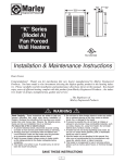
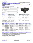
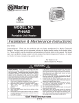
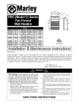
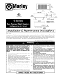
1
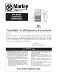
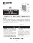
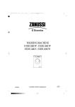
BACK BOX
HEATER
ASSEMBLY
File #E21609
C Series
B Model
Fan-Forced Wall Heaters with
Clip’n’Fit® Board
FRONT COVER
US Patent No. 6,172,343
Installation & Maintenance Instructions
Dear Owner,
Congratulations! Thank you for purchasing this new heater manufactured by Marley Engineered Products. You have made
a wise investment selecting the highest quality product in the heating industry. Please carefully read the installation and
maintenance instructions shown in this manual. You should enjoy years of efficient heating comfort with this product from
Marley Engineered Products... the industry’s leader in design, manufacturing, quality and service.
... The Employees of Marley Engineered Products
WARNING
Read Carefully - These instructions are written to help you prevent
difficulties that might arise during installation of heaters. Studying
the instructions first may save you considerable time and money
later. Observe the following procedures, and cut your installation
time to a minimum. CAUTION - TO REDUCE RISK OF FIRE AND
ELECTRIC SHOCK:
1.
Disconnect all power coming to heater at main service panel
before wiring or servicing.
2. All wiring must be in accordance with the National and Local
Electrical Codes and the heater must be grounded.
3. Verify the power supply voltage coming to heater matches the
ratings printed on the heater nameplate before energizing.
4. This heater is hot when in use. To avoid burns, do not let bare
skin touch hot surfaces.
5. Do not insert or allow foreign objects to enter any ventilation or
exhaust opening as this may cause an electric shock, fire, or
damage to the heater.
6. Grille and discharge air are hot when in use. Do not install or use
heater in any area where airflow from heater may be blocked or
obstructed. Do not install behind doors, furniture, towel racks,
curtains, or boxes. Hot air may damage certain fabrics and plastics. Always keep electrical cords, beddings, crates, drapes, and
other combustibles away from heater. Do not install heater in
ceiling.
7. A heater has hot and arcing or sparking parts inside. Do not use
it in areas where gasoline, paint, or flammable liquids are used
or stored.
8. Use this heater only as described in this manual. Any other use
9.
10.
11.
12.
13.
14.
15.
16.
!
not recommended by the manufacturer may cause fire, electric
shock, or injury to persons.
This heater is not approved for use in corrosive atmospheres
such as marine, green house, or chemical storage areas.
When wall mounted, heater must only be installed in a vertical
direction (motor below element) as shown in this manual. Do not
install sideways, upside down.
Heater must be installed with CBB (Type CO2-BB) Back Box.
The following minimum clearances must be maintained:
• Wall Mounting:
Heater to floor - 4.5 in. (114 mm)
Heater to adjacent wall - 4.5 in. (114 mm)
Heater to ceiling - 12 in. (305 mm).
• Ceiling Mounting (Max 1000 Watts)
Heater to any wall - 12” (305mm)
When wiring, power supply must enter through knockouts in left
side of back box. Do not use the knockouts in right side back
box. Refer to Fig. 1.
To determine which side is left or right:
1.) Orient the back box so the “TOP” marking and arrows are
visible and upright; and 2.) Ensure that the fan deck is oriented
with the element side on the “TOP” side of the back box.
Do not operate heater without grille installed.
Do not use heater for dry out. Paint, plaster, sawdust, and drywall sanding dust will damage heater and must be kept out of
heater.
Keep heater clean. See maintenance and cleaning instructions
on page 3.
SAVE THESE INSTRUCTIONS
GENERAL
Wall Mounted
•The C series heaters are designed for recessed installation in 2 X 4 stud or
larger wall using the model CBB (Type CO2-BB) back box. The heater may
be wired using standard building (60 degrees C minimum) wire.
!
CAUTION
TO PREVENT POSSIBLE WIRING DAMAGE CUT EXCESS SUPPLY
WIRE INSIDE BACKBOX TO PROVIDE APPROXIMATELY 6 INCHES
FOR CONNECTION TO HEATER LEADS. AFTER CONNECTIONS ARE
MADE, MAKE SURE CONNECTIONS ARE TIGHT AND ALL WIRING IS
POSITIONED AWAY FROM FAN BLADE AND HEATING ELEMENT.
•The optimum mounting height for this heater is 18” to 24” (457mm to
610mm) from floor to bottom of back box. In any case, do not install closer
than 4.5” (114mm) from the floor or adjacent wall.
Ceiling Mount
•The C Series heaters are designed for ceiling mount provided the wattage
does not exceed 1000 watts. In order for your heater to be rated for
ceiling application, the heater must be trimmed back to 1000 watts or less.
(See Change Wattage Output below)
•The optimum clearances to any wall surface are 12 inches. Do not mount
heater in the ceiling if these clearances are not met.
•Ceiling heaters can be recessed or surfaced mounted.
NOTE: Lead holes for a #8 sheet metal screw have been provided in the sides
of the back box. After the finished wall or ceiling has been put up, drive a #8(m4)
sheet metal screw (recommended 1”(25mm) long) through the side of the box
not mounted to the stud.(joist) This will prevent the back from pulling out when
installing the heater assembly. (See Figure 1)
LAMP
R
LIMIT
CONTROL TCO
RED
Heaters are also approved for semi-recessed or surface mounting on walls. Refer to
instructions for installations of the CSM Surface Mounting frame.
L1
RED
INSTALLATION OF BACK BOX
IN NEW CONSTRUCTION
ELEMENT
BLACK
BLACK REMOTE OR
NOTE: If the finished wall surface is already up, follow instructions for
“INSTALLATION OF BACK BOX IN EXISTING CONSTRUCTION”.
1.
REMOTE 1
POLE T'STAT
L2/N
M MOTOR
OPTIONAL 2
POLE T'STAT
3
Allow for the thickness of the finished surface when installing the back
box. The edge of the back box must be installed flush with the finished
surface. Markings on the side of the back box for 1/2” or 5/8” finishing
wall are provided.
1
2
BLUE
RED
JUMPER JUMPER
CLIP'N'FIT®
Figure 2 Wiring Diagram
BEND
OUT
TAB
NOTE: Heaters are factory wired per nameplate, voltage and wattage. Refer to
Table1, page 3 for details. See “TO CHANGE WATTAGE OUTPUT” section if
lower wattage is desired and make change before installating heat deck.
CABLE CLAMP
LEAD
HOLES
SUPPLY
WIRING
CABLE
BACK BOX
INSTALLATION AND WIRING
OF HEATER / FAN ASSEMBLY
1.
Figure 1
2.
Following wiring diagram (Figure 2) connect supply wires to heater leadwires in back box using appropriate wire connectors.
NOTE: For 120 volt heaters connect the white neutral supply lead to the heater’s white
or red with white flag marker pigtail lead, and connect the black supply lead to the black
pigtail lead.
NAILS OR
SCREWS
Determine which side of the back box is to be mounted against a stud or
joist and bend the tabs at the rear corners out 90 degrees so that the
back box will be square with the stud after installation.
3.
Remove one of the knockouts on left side of the back box and install a
cable or conduit connector. (See warning 13)
4.
Position back box against side with studs or ceiling joist and secure with
nails or screws as shown in Figure 1.
Run power supply cable through the connector, leaving about 6” of wire
inside the box.
6.
Connect the supply cable ground wire to green ground wire provided.
Secure supply ground wire under green ground screw in back box (or
green ground wire if provided).
3.
Fit heater/fan assembly into back box making sure all wiring is powitioned
away from fan and heating element.and secure in place with (2) screws
provided through the center slots in the sides of the fan assembly.
WATTAGE
C1512IF
C2024IF
C2224IF
C1512T2
C1524T2
C2028IF
C2024T2
C2224T2
@120V @208V @240V @208V @208V @240V @208V @240V
NOTE: The back box must be installed to a wall stud or ceiling joist and
secured using nails or screws as shown in Figure 1.
5.
2.
1500
1125
750
375
1125
844
563
281
1500
1125
750
375
2000
1500
1000
500
1500
1125
750
375
2000
1500
1000
500
1688
1266
844
422
2250
1688
1125
563
Jumper 1
Blue
Jumper
Jumper 2
Red
Jumper
Leave In
Clip Out
Leave In
Clip Out
Leave In
Leave In
Clip Out
Clip Out
NOTE: Lead holes for a #8 sheet metal screw have been provided in the sides
of the back box. After the finished wall or ceiling has been put up, drive a
#8(m4) sheet metal screw (recommended 1”(25mm) long) through the side of
the box not mounted to the stud. This will prevent the back box from pulling
out when installing the heater assembly. (See Figure1)
INSTALLATION OF BACK BOX
IN EXISTING CONSTRUCTION
1. The edge of the back box must be installed flush with the finished surface.
Determine which side of the back box is to be mounted against a stud or joist
and bend the tabs at the rear corners out 90 degrees so that the back
box will be square with the stud after installation. (See Figure 1).
2. Carefully cut a hole measuring 9-3/8”(239mm) wide by 11-1/8”(284mm)
long. One edge of the hole must be cut along edge of the wall stud.
Figure 3 Clip’n’Fit® Board
3. Bring power supply cable to heater mounting location leaving at least
10”(255mm) of cable for wiring.
TO CHANGE WATTAGE OUTPUT
4. Remove desired knockout on left side of back box.
The chart below shows the wattages available by model. Each heater is factory wired for its maximum wattage. The last two columns in the chart refer to the
jumpers on the CLIP’n’FIT® Board. To change wattage, clip out jumper 1 and/or
jumper 2 as shown in the chart below. Completely remove jumpers by clipping
at both ends as close to the board as possible.
5. Install cable clamp to cable and install into back box, leaving at least
6”(152mm) of cable in box for wiring.
6. Connect the supply cable ground wire to green ground wire provided.
7. Fit back box into mounting hole in wall by first inserting cable end of box then
rotating box into position.
8. Secure box to wall stud or ceiling joist using nails or screws.
2
INSTALLATION OF FRONT COVER (GRILLE) AND
THERMOSTAT KNOB
1.
Fasten front cover to heater assembly using the (2) long
screws supplied.
2.
Fit the thermostat knob onto the thermostat shaft (if provided)
and push into place.
a
CAUTION
THE ILLUMINATED INDICATOR LIGHT SIGNIFIES THE HEATER HAS BEEN
SUBJECTED TO SOME ABNORMAL CONDITION CAUSING IT TO OVERHEAT.
CHECK HEATER TO INSURE THAT IT HAS NOT BEEN BLOCKED IN ANY MANNER (IF SO, REMOVE BLOCKAGE). IF THERE IS NO INDICATION OF BLOCKAGE IT IS RECOMMENDED THE HEATER BE CHECKED BY A REPUTABLE
ELECTRICIAN OR REPAIR SERVICE TO INSURE THE HEATER HAS NOT
BEEN DAMAGED. DO NOT CONTINUE TO USE HEATER IF LIGHT IS ON.
HEATER CHECKOUT AND OPERATION
(If internal thermostat provided)
1.
After heater is completely assembled, rotate thermostat knob
counterclockwise until control stops. This is the minimum heat
setting.
2.
Turn power supply to heater “ON” at main switch panel.
3.
Heater should not operate. If it operates disconnect power and
recheck wiring.
4.
Rotate thermostat clockwise until it stops (maximum heat setting).
5.
Heater and fan should come on. If heater and fan do not come
on, disconnect power and check wiring.
6.
Allow heater to continue to operate until room temperature
reaches desired comfort level. Then rotate thermostat knob
counterclockwise slowly until thermostat clicks off.
7.
If may be necessary to readjust thermostat a time or so until
exact comfort level is attained. Rotation in the clockwise direction will increase the amount of time the heater will produce
heat. Rotation in the counterclockwise direction will reduce the
amount of time the heater is on.
NAMEPLATE
MODEL NO.
NOTE: For best results, the heater should be left “ON” constantly during the
heating season as the thermostat, when properly set, will maintain the desired
temperature. In the full counter-clockwise position the heater will remain off
until the room temperature drops well below freezing.
240/208
VOLTS AC
9.4/7.0/4.7/2.3
8.1/6.1/4.1/2.0
AMPS
CAUTION
TO CLEAN HEATER: The heater should be cleaned annually for maximum
efficiency. Before cleaning be sure power is off and heater is cool. First,
remove knob by pulling straight out, then remove front grille and clean blower wheel using a vacuum cleaner with a brush attachment. The grille may
be cleaned with a slightly damp rag if desired.
TABLE 1
MODEL VOLTS WATTS/AMPS WATTS/AMPS WATTS/AMPS WATTS/AMPS
C1512IF
120
1500W/12.5
1125W/9.4
750W/6.3
375W/3.1
C1512T2
240
1500W/6.3
1125W/4.7
750W/3.1
375W/1.6
C1524T2
208
1125W/5.4
844W/4.1
563W/2.7
281W/1.4
C2028IF
208
200W/9.6
1500W/7.2
1000W/4.8
500W/2.4
C2024IF
240
2000W/8.3
1500W/6.3
1000W/4.2
500W/2.1
C2024T2
208
1500W/7.2
1125W/5.4
750W/3.6
375W/1.8
C2224IF
240
2250W/9.4
1688W/7.0
1125W/4.7
563W/2.3
C2224T2
208
1688W/8.1
1266W/6.1
844W/4.1
422W/2.0
NOTE: “IF” Inner Frame models must be used with CBB (Type CO2-BB)
Back Box. “T2” Thermostat Models include integral thermostat.
NOTE: For installations over 7500 ft. above sea level we recommend to use
heaters with wattages under 1500 watts.
TABLE 2
#14
#12
2250/1688/1125/563
1688/1266/844/422
WATTS
60HZ1PH
MARLEY ENGINEERED PRODUCTS
BENNETTSVILLE, SC 29512 USA
OPERATIONAL NOTICE
Your heater is equipped with an automatic reset limit control that will automatically turn the heater OFF to prevent overheating. Should this occur, the
red warning light will illuminate and will continue to shine until the limit
resets. Your heater is also equipped with a backup “one shot” thermal protection fuse that will permanently disable the unit, to prevent a fire, if the
reset limit fails. If the red warning light illuminates and the heater never
restarts, the “one shot” thermal protection fuse has been activated and you
should consult the factory.
0 thru 12
12.1 thru 16
0403
774G LISTED
ROOM HEATER
TYPE
CO2
USE ONLY WITH CO2-BB BACK BOX.
DO NOT OPERATE WITHOUT GRILLE IN PLACE.
SÓLO DEBE USARSE CON LA CAJA POSTERIOR CO2-BB.
NO DEBE ENCENDERSE SIN LA REJILLA.
UTILISER SEULEMENT AVEC UN BOÎTERIER ARRIÉRE CO2-BB.
NE PAS UTILISER SE LA GRILLE N’EST PAS EN PLACE.
TO REDUCE RISK OF FIRE AND ELECTRIC SHOCK, DISCONNECT ALL
POWER COMING TO HEATER AT MAIN SERVICE PANEL BEFORE SERVICING OR PERFORMING MAINTENANCE.
WIRE SIZE (COPPER)
DATE CODE
E
L
P
M
A
EX
a
TOTAL AMPS
C2224IFB
FAN FORCED WALL HEATERS
CALEFACTOR DE PARED CON VENTILADOR
APPAREL MURAL À AIR PULSÉ POUR
MAINTENANCE
!
!
CIRCUIT BREAKER
OR FUSE SIZE
15 Amps
20 Amps
3
4104-2218-005
LIMITED WARRANTY
All products manufactured by Marley Engineered Products are warranted against defects in workmanship and materials for one year from date of installation, except heating elements which are warranted against defects in workmanship and materials for five years from date of installation. This warranty does not apply to damage from
accident, misuse, or alteration; nor where the connected voltage is more than 5% above the nameplate voltage; nor to equipment improperly installed or wired or maintained in violation of the product’s installation instructions. All claims for warranty work must be accompanied by proof of the date of installation.
The customer shall be responsible for all costs incurred in the removal or reinstallation of products, including labor costs, and shipping costs incurred to return products
to Marley Engineered Products Service Center. Within the limitations of this warranty, inoperative units should be returned to the nearest Marley authorized service center or the Marley Engineered Products Service Center, and we will repair or replace, at our option, at no charge to you with return freight paid by Marley. It is agreed that
such repair or replacement is the exclusive remedy available from Marley Engineered Products.
THE ABOVE WARRANTIES ARE IN LIEU OF ALL OTHER WARRANTIES EXPRESSED OR IMPLIED, AND ALL IMPLIED WARRANTIES OF MERCHANTABILITY AND
FITNESS FOR A PARTICULAR PURPOSE WHICH EXCEED THE AFORESAID EXPRESSED WARRANTIES ARE HEREBY DISCLAIMED AND EXCLUDED FROM
THIS AGREEMENT. MARLEY ENGINEERED PRODUCTS SHALL NOT BE LIABLE FOR CONSEQUENTIAL DAMAGES ARISING WITH RESPECT TO THE PRODUCT, WHETHER BASED UPON NEGLIGENCE, TORT, STRICT LIABILITY, OR CONTRACT.
Some states do not allow the exclusion or limitation of incidental or consequential damages, so the above exclusion or limitation may not apply to you. This warranty
gives you specific legal rights, and you may also have other rights which vary from state to state.
For the address of your nearest authorized service center, contact Marley Engineered Products in Bennettsville, SC, at 1-800-642-4328. Merchandise returned to the factory must be accompanied by a return authorization and service identification tag, both available from Marley Engineered Products. When requesting return authorization, include all catalog numbers shown on the products.
HOW TO OBTAIN WARRANTY SERVICE AND
WARRANTY PARTS PLUS GENERAL INFORMATION
1. Warranty Service or Parts
2. Purchase Replacement Parts
3. General Product Information
1-800-642-4328
1-800-654-3545
www.marleymep.com
Note: When obtaining service always have the following:
1. Model number of the product
2. Date of manufacture
3. Part number or description
470 Beauty Spot Rd. East
Bennettsville, SC 29512 USA
ECR 36623
Part No. 5200-2638-003
09-06
4