1
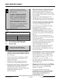
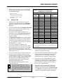
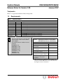
Control Panels
D9412GV2/D7412GV2
Release Notes for Version 7.05
January 2007
Trademarks
Molex® is a registered trademark of Molex Incorporated.
1.0
Requirements
Table 1: Required Handlers
D5200 Handler
GV2MAIN
RADXUSR1
RADXUSR2
RADXPNTS
RADXSKED
GV2AUX
RADXAXS
9000MAIN
RADXAUX1
Version
1.02
1.06
1.05
1.08
1.04
1.02
1.06
NA
NA
Changes and Notes
New handler for the GV2 Series Control Panels, version 7.05
Updated to support GV2 Series Control Panels
Updated to support GV2 Series Control Panels
Updated to support GV2 Series Control Panels, version 7.05
Updated to support GV2 Series Control Panels
New handler for the GV2 Series Control Panels, version 7.05
Updated to support GV2 Series Control Panels
Not compatible with the GV2 Series Control Panels
Not compatible with the GV2 Series Control Panels
During the development of the GV2 Series
Control Panels, some version numbers
were skipped.
The following version numbers were not
released.
Table 2: Supporting Literature for D9412GV2/
D7412GV2 with Version 7.05 Firmware
Document Name
D9412GV2/D7412GV2 Program
Entry Guide
D9412GV2/D7412GV2 Program
Record Sheet
D9412GV2/D7412GV2 Operation
and Installation Guide
D9412GV2/D7412GV2 Approved
Applications Compliance Guide
GV2 Series Program Entry Guide
Supplement for SIA CP-01
Compliance
GV2MAIN v1.01
RADXUSR1 v1.05
RADXUSR2 v1.04
RADXPNTS v1.07
RADXSKED v1.03
GV2AUX v1.01
RADXAXS v1.05
•
Part Number*
F01U003636-02
F01U003635-02
F01U003641-02
F01U003639-02
F01U032733-01
Older revisions have alphabetic revision identifiers (for
example, F01U003636B) and do not provide information
that supports version 7.05 firmware.
D9412GV2/D7412GV2
•
When a Route Group is configured with an IP
destination in the primary path and a telephone
number in the backup path, a break in the
Network Link Integrity now annunciates locally.
Refer to Enhanced Communication Trouble on page 6
for more details.
•
Changes ensure that the D928 primary and
secondary phone line failure LEDs operate only
when the Phone Supervision interval is enabled.
Use an analog telephone line with the
D5200. The D5200 dials only pulses.
•
Refer to Section 10 Updating Handlers in
the D5200 Programming Manual
(P/N: 74-06176-000-B) for details on
updating handlers.
Corrections improve the reliability of the direct
connection communication method between the
control panel and RPS through a D5360.
•
Corrections prevent a programmed # symbol
from being dialed as a zero (0).
•
If multiple areas use the same relay for the
A# Perimeter Armed area-wide relay function,
the relay activates when all areas are perimeter
armed. The relay deactivates when the first area
disarms.
•
The sensitivity of the Ground Fault feature is
modified to be equivalent with Version 6.90 and
to prevent false reports.
•
The authority scope problem with the Menu Key
Lock feature, described in the GV2 Series Control
Panels Menu Key Lock Technical Service Note
(P/N: F01U032240B), is corrected.
•
When a user changes the time and date in the
control panel, the corresponding event now
reports consistently the identification of the user
who made the change.
•
Event reporting for a relay that is set or reset using
the RPS Diagnostics screen is changed to indicate
that the operation was done "By Programmer"
instead of "By Remote.” For example, setting a
relay with RPS now sends a Relay Set by
Programmer at SDI 88 event.
•
Corrections improve the user interface for the
Door Control sub-menu (CMD 46) in the D1260
and D1260B Keypads.
•
Changes now require users to have an L# Door
Control authority level to enter the Door Control
menu. Formerly, only the L# Cycle Door
authority was required.
•
Corrections to the Door Control menu
(COMMAND 46) for the D1260 and D1260B
Keypads restrict the menu items based on the
L# Cycle Door, L# Unlock Door and
L# Secure Door settings.
Use Remote Programming Software
(RPS) version 5.5 and above with this
software version.
To acquire an update for your D5200
Programmer, call the Bosch Security
Systems, Inc. Handler Update System,
toll-free, at (800) 657-4584. Make a
separate phone call for each handler.
Refer to Table 3 for the required ROM kit part
number.
Table 3: ROM Kit Part Numbers for Version 7.05
Control Panel Model
D9412GV2
D7412GV2
Part Number
R20-9412V2-0705
R20-7412V2-0705
2.0
Corrections and Changes
2.1
Version 7.05
Version 7.04 was skipped during
development and was not released.
•
The default configuration parameters for Path #
ACK Wait Time and Path # Number of Retries
in Version 7.05 firmware are sufficient to meet UL
864 requirements
•
Changes reset the User Code Tamper condition
when it is reported to the central station in an
Expanded Test Report.
•
Changes ensure that the keypad emits a tone
when a point is activated during a Walk Test.
•
Changes prevent the ALARM SILENCED message
from showing on the keypads when the Silent
Alarm bell timer expires. This corrects the
problem described in the GV2 Series Control Panels
Invisible Points Technical Service Note
(P/N: F01U032203).
D9412GV2/D7412GV2 Release Notes for Version 7.05
F01U003637-02
Page 2
© 2007 Bosch Security Systems, Inc
D9412GV2/D7412GV2
•
Minor corrections improve the user interface for
the following function list menus on the D1260
and D1260B Keypads:
Table 4: Parameters for Heartbeat Poll
Configuration in Version 7.031
Master Arm?
Master Arm Instant?
Perimeter Arm Delay?
Perimeter Arm Inst?
Disarm?
2.2
Version 7.03
•
Changes allow Custom Functions to operate
correctly in the Function List when CC# Menu
Lock is set to Yes on the D1260 and D1260B
Keypads.
•
Corrections disassociate the L# Display Revision
authority level from the Service Menu on the
D1260 and D1260B Keypads.
•
Corrections ensure that the authority level
permissions of each L# Custom Function ###
are strictly associated with the correct Custom
Function number.
•
If Expanded Test Report is set to Yes, Summary
Fire Supervision, Summary Fire Fault, Summary
Control Point Fault and Summary Point Device
are now included when a test report is sent using
COMMAND 41 or a sked.
•
•
Corrections enhance the reliability and
performance of RPS network connection. These
corrections also decrease the delay in reporting a
break in the Ethernet connection to the control
panel’s Network Interface Module within the time
limits required by UL.
For UL 1610 Line Security (formerly Grade AA)
Intrusion System installations and for UL 864
Commercial Fire installations, use the parameters
shown in Table 4 on page 3 when configuring the
Heartbeat Poll. For additional details, refer to
Programming Path Numbers and IP Addresses for
Enhanced Communications in the
D9412GV2/D7412GV2 Program Entry Guide
(P/N: F01U003636).
The recommended settings in Table 4
(Poll Rate of 75) enable the control panel
to annunciate locally, within 200 seconds,
any break in the network communication
path.
Number of
IP Paths
1
1
1
1
1
1
1
1
1
1
1
1
1
1
1
Poll Rate
(sec)
30
30
30
30
30
60
60
60
60
752
90
90
90
120
145
2
3
4
75
2
75
2
75
ACK Wait
Time (sec)
6
8
10
12
14
6
8
10
12
102
6
8
10
6
5
2
2
8
2
6
2
5
Number of
Retries
2 to 19
2 to 12
2 to 8
2 to 5
2 to 3
2 to 14
2 to 8
2 to 5
2
32
2 to 9
2 to 4
2
2 to 4
2
2
3
2
3
2
3
1
The parameters in this table are for Version 7.03 only.
2
Recommended settings for the corresponding number
of IP paths.
•
Corrections allow the Path # Retry Count value
to be used as the number of retries instead of the
number of transmission attempts.
•
When the control panel disconnects from an RPS
session using the network and the “Reset Panel”
checkbox is set, the control panel now logs a
Remote Reset event instead of a Reboot Event.
•
Corrections now prevent the D9412GV2 and
D7412GV2 Control Panels from performing a
watchdog reset when an area is armed with more
than 75 manually bypassed points or has more
than 75 force bypassed points.
•
Corrections now prevent the D9412GV2 and
D7412GV2 Control Panels from performing a
watchdog reset when an area with A# Area Type
set to Shared is individually armed. Shared areas
should not be individually armed or disarmed.
D9412GV2/D7412GV2 Release Notes for Version 7.05
© 2007 Bosch Security Systems, Inc.
Page 3
F01U003637-02
D9412GV2/D7412GV2
•
•
•
•
Corrections now prevent a duress passcode from
being accepted by a keypad currently in an area
that has A# Duress Enable set to No. If the
Duress feature is used, A# Duress Enable should
be set to Yes for all areas.
The alternate function of Area 6 Silent Alarm
Relay parameter was removed. To enable Fire
Trouble Resound support, use
GV2AUX→MISCELLANEOUS→Fire Trouble
Resound.
The alternate function of Area 5 Silent Alarm
Relay parameter was removed. The Ground Fault
detection feature is solely enabled by closing
Switch S4 on the D9412GV2 and D7412GV2
Control Panels.
Changes now suppress the ALARM SILENCED
message when a user attempts to silence a Ring
Until Restored fire bell. A fire alarm generated by
a point with the Ring Until Restored (P# Ring Til
Rst) feature set to Yes will sustain the fire bell
until the sensor is restored.
2.3
Version 7.02
•
The Phone Line Supervision feature has improved
accuracy in detecting the phone line.
•
The Modem IIIa2 product ID is changed to the
same ID as the G Series control panels, allowing
compatibility with non-Bosch central station
receivers.
2.4
Version 7.01
The following are corrections and changes made since
Version 6.60 in the G Series Control Panels.
•
The GV2 Series Control Panels have the same
response to low AC voltage as to an AC failure.
•
If the control panel battery is detected as missing,
the Walk Test function skips the Battery Test.
•
Several system stability issues are fixed to prevent
erroneous Parameter Checksum Failures.
•
The Service Walk Test on the D7412GV2 and
D7212GV2 now shows the correct maximum
number of points in the system.
•
Corrections ensure that acknowledged Silent
Alarms scroll correctly on the idle text displays on
the D1260 and D1260B Keypads.
•
The Telephone Ground Start circuitry and
associated programming prompts are removed
from the GV2 Series Control Panels.
•
Corrections now allow a user’s token, with L#
Disarm Level set to I, to disarm the interior of all
areas within the scope of the keypad programmed
at D# CC# Scope. The keypad programmed at
D# CC# Scope must have CC# Passcode
Follows Scope set to Yes to disarm the interior of
all areas within scope.
•
The GV2 Series Control Panels require the D6500
receiver to have a D6511 MPU card at version
1.06 or above for maximum communication
efficiency.
•
The Extend Close (COMMAND 51) feature was
modified to prevent the new Close Window time
from setting to a value earlier than the current
time.
•
When disarming an area with Two Man Rule
enabled, the keypad waits for the time equal to the
exit delay for the area. If the second passcode is
not entered before the prompt times out, then the
rule resets and waits for the first passcode again.
•
Several changes in this release prevent local alarm
events from being sent intermittently to the central
station. All local alarm events should now remain
local.
•
Corrections now allow the panel-wide
Communications Failure Relay output to activate
when events in Route Groups 2 through 4 do not
reach the central station. Previously this relay
output activated only on a communication failure
for Route Group 1.
D9412GV2/D7412GV2 Release Notes for Version 7.05
F01U003637-02
Page 4
© 2007 Bosch Security Systems, Inc.
D9412GV2/D7412GV2
Battery Recharge Circuit Monitor
3.0
New Features
3.1
Version 7.05 – UL 864 and
ANSI/SIA CP-01 Compliance
3.1.1
UL 864 Compliance
Version 7.04 was skipped during
development and was not released.
Support for D1255RB and D1256RB Keypads, and
D1257RB Annunciator
The D9412GV2 and D7412GV2 Control Panels,
version 7.05 and above, support the new D1255RB
and D1256 Keypads and the new D1257RB
Annunciator. These new devices have four LEDs
added to indicate Fire Alarm, Trouble, Supervisory,
and Alarm Silenced. This LED feature is enabled
automatically when a D125xRB device is installed.
Refer to the D9412GV2/D7412GV2 Program Entry
Guide (P/N: F01U003636-01). Previous versions of the
program entry guide do not include information
related to the D125xRB devices.
Idle Text Scroll Lock
To comply with UL864 9th Edition requirements for a
Fire Command Center, set the idle text scroll lock
feature to Yes. Select GV2MAIN→COMMAND
CENTER→Command Center Assignments→
CC# Idle Scroll Lock. The D125xRB keypad idle
text display locks until a user manually acknowledges
an alarm or trouble condition. The unacknowledged
idle text display updates automatically to the highest
priority alarm or trouble type if one occurs. When the
user presses the [NEXT] key, the idle display is
acknowledged and the scroll is unlocked.
Auxiliary Power Supply Monitor
A new point type is added to monitor auxiliary power
supply modules. If P# Point Type is programmed
with 11 – Aux AC Supervision and the associated
point goes off-normal, a Point Trouble condition
occurs immediately. Any Trouble events generated
from an Aux AC Supervision point are delayed by the
time programmed in AC Fail Time. This feature is
necessary to comply with UL864 9th Edition
requirements.
Control panel firmware now monitors the battery
recharge circuit to ensure that the backup power of the
control panel is available when needed. If the control
panel detects that the on-board battery is not
recharging correctly because of a hardware failure, a
battery trouble condition occurs. This feature is always
on and cannot be disabled.
Reset Switch Trouble Annunciation
A new feature is added to annunciate trouble locally if
the Reset Switch (S1) is closed. The trouble
annunciation is an intermittent beep from the onboard sounder. The sounder is silenced when the
switch is opened. This feature is always on and cannot
be disabled.
Fire Bypass Trouble Annunciation
The Fire Bypass warning display is modified to
generate a Trouble warning tone that can be silenced
with [COMMAND][[4]. The trouble condition selfclears when all bypassed fire points within the
keypad’s scope return to service. This feature is always
on and cannot be disabled.
Summary Fire Relay Options
An option is added that changes the duration of the
Panel Wide Summary Fire Relay output. Select
GV2AUX→MISCELLANEOUS→Fire Summary
Sustain:
Yes Summary Fire Relay clears when all Fire Alarms
are cleared from the display.
No Summary Fire Relay clears when the area Fire
Alarms are silenced and all area Fire Points
return to normal.
The default option is No. This option is consistent
with the Summary Fire Relay operation in the
previous versions of the D9412G and D7412G
Control Panels. This feature provides a way to
maintain the fire strobes after the alarm bell outputs
are silenced.
D9412GV2/D7412GV2 Release Notes for Version 7.05
© 2007 Bosch Security Systems, Inc.
Page 5
F01U003637-02
D9412GV2/D7412GV2
Enhanced Communication Trouble
The default configuration parameters for
the poll rate, ACK wait time, and number
of retries complies with UL.
Entry Delay Warning
Prompt: A# Entry Warning
When enabled, the Alarm Bell output pulses ON and
OFF for the last ten seconds of the Entry Delay.
Exit Time Restart
When an Enhanced Communication Trouble
condition occurs, it generates a system-wide trouble
message (COMM TRBL SDI ##). The new trouble
message includes the address of the virtual SDI device.
Address 88 = Enhanced SDI Path 1
Address 89 = Enhanced SDI Path 2
Address 90 = Enhanced SDI Path 3
Address 91 = Enhanced SDI Path 4
The trouble condition is also sent through a backup
path to the central station as Communication Trouble
SDI ##, using the same virtual address numbers as the
trouble messages. The communication trouble event
also creates new Modem IIIa2 messages that the
central station might need to add to their automation
software. Refer to Events 157 to 160 in the Modem
IIIa2 Messages section of the Appendix in the D6600
Computer Interface Manual (P/N: 4998122703) for the
details of central station data changes.
3.1.2
ANSI/SIA CP-01 Compliance
Minimum system requirements for
Classification in accordance with
ANSI/SIA CP-01-2000:
•
UL Listed and Classified control unit
Model D9412GV2, D7412GV2, or
D7212GV2
•
UL Listed and Classified keypad Model
D1256, D1257, D1260, D1255,
D1255R, or D1255 RW
•
UL Listed Local Bell
For detailed descriptions and settings
required for SIA CP-01 compliance, refer
to the GV2 Series Program Entry Guide
Supplement for SIA CP-01 Compliance
(P/N: F01U032733).
Prompt: A# Exit Restart
When enabled, this feature causes an area’s Exit Delay
timer to restart upon re-entry. To consider the area as
vacated, the control panel must detect a point with a
delay alarm response changing from normal to offnormal, and back to normal. When vacated, a fault on
any point with a delay alarm response during the
remaining Exit Delay causes the countdown to restart
from the beginning.
Exit Error
If a point with a delay alarm response remains offnormal when the Exit Delay expires, the Entry Delay
starts. If the system is not disarmed within the
programmed time, an Exit Error Alarm is generated.
This feature is always enabled and has no
configuration parameters.
Master Arm – No Exit
Prompt: A# Arm No Exit
When enabled, this feature sets an area’s arming state
to Perimeter Armed if no perimeter points with
delayed responses are faulted and returned to normal
in that area during the Exit Delay of a Master Arm
attempt. This feature applies to CMD 1, Passcode
arming, Keyswitch and remote master arming.
Fixed Passcode Length
Prompt: Passcode Length
When enabled, this feature sets a fixed length to all
user passcodes. During Entry Delay, the code is
accepted when the last digit is pressed to disarm the
area. At any other time, the [Enter] key is required for
acceptance of the code.
To be ANSI SIA CP-01 compliant, the
Fixed Passcode Length feature must be
enabled. For backward compatibility, Fixed
Passcode Length is disabled by default
Exit Delay Warning
Prompt: A# Exit Warning
If you change the Fixed Passcode Length
value to 4 or greater, you must also change
the default Service Passcode to match the
new length.
When enabled, the Exit Delay tone at all keypads in
an area about to arm is replaced by a fast Trouble
Tone for the last ten seconds. The Alarm Bell output
also pulses ON and OFF for the last ten seconds of the
Exit Delay.
D9412GV2/D7412GV2 Release Notes for Version 7.05
F01U003637-02
Page 6
© 2007 Bosch Security Systems, Inc.
D9412GV2/D7412GV2
Remote Arm/ Disarm Output
Swinger Shunt Enhancement
Prompt: Remote Warning
Prompt: Swinger Count
When enabled, this feature uses the Alarm Bell output
to annunciate the arming and disarming of an area by
remote means, such as by keyswitch, key fob, or
remote software (RPS, BIS Security Engine). When
arming occurs, the output pulses for two seconds.
When disarming occurs, the output pulses ON, OFF,
ON, OFF for two seconds each.
The Swinger Bypass feature is enhanced to allow a
variable number of faults before automatically
bypassing a point. When a point with P# Swinger
Bypass set to Yes is faulted the number of times
programmed in Swinger Bypass Count, it is
automatically bypassed.
Abort Window
When the control panel is powered up, or the system
is rebooted, all points are now temporarily bypassed
for 60 seconds. This feature is always enabled and has
no configuration parameters.
Prompts: CC# Abort Display, P# Alarm Abort,
Abort Window
This feature is always enabled, but it only applies to
intrusion alarm events generated by points that have
P# Alarm Abort set to Yes and P## Invisible Pt set
to No. When an intrusion alarm event is annunciated,
the user has the duration of time programmed in the
Abort Window prompt to enter a valid passcode to
prevent the alarm event from being transmitted to the
central station. When transmission is aborted
successfully, any keypad with CC# Abort Display set
to Yes shows ALARM NOT SENT.
Power-Up Standby
Walk Test Enhancements
Cancel Window
The Walk Test procedure is enhanced to provide
more user feedback. The Walk Test now indicates that
the menu is ready to time out, and clearly notifies the
user at all keypads in the area of operation when a test
is in progress. Additionally, the Walk Test procedure
issues point trouble conditions for any 24-hour points
that remain off-normal when the Walk Test menu idle
time expires. These enhancements are always enabled
and have no configuration parameters.
Prompt: CC# Cancel Display
3.2
Version 7.01
The burglary alarm cancel window is enhanced by an
optional keypad display. When CC# Cancel Display
is set to Yes and Cancel Report is set to Yes, an
alarm silence operation after event transmission
displays CANCEL RPT SENT on the keypad. The
burglary alarm cancel window duration is the time
programmed in the A# Alarm Bell prompt.
3.2.1
D1260 Keypad Enhancements
Duress Passcode
Prompts: Duress Type, A# Duress Enable,
L## Send Duress
A new duress option is available that allows any
passcode with the L# Send Duress permission set to
Yes to always send a Duress Alarm event upon entry.
This feature allows the control panel to have uniquely
dedicated passcodes for all users. Additionally, when
this feature is enabled, the Passcode +1 and +2
features are disabled for compliance with SIA CP-012000 regulations.
The D1260 Keypad must have firmware version 1.03
or above to operate with the GV2 Series Control
Panels. An update kit (P/N: R19-D1260-0103) is available
from Customer Service: (800) 289-0096.
Custom Function Enhancements: The custom
functions now support the soft keys (the eight
unmarked keys around the display) on the D1260
Keypad. This change makes the operation of custom
functions on D1260 Keypad easier to program.
D1260 Keypads with firmware version 1.03 or above
do not need to check the control panel firmware
revision when communicating with GV2 Series
Control Panels; therefore, the Display Revision
(COMMAND 59) keypad (command center) function
can be password protected.
The D1260 and D1260B Keypads can be used with
CC# Supervision set to No to allow multiple
Enhanced Keypads at the same address.
D9412GV2/D7412GV2 Release Notes for Version 7.05
© 2007 Bosch Security Systems, Inc.
Page 7
F01U003637-02
D9412GV2/D7412GV2
3.2.2
New Firmware Features:
Two Man Rule: Two Man Rule requires two unique
passcodes to be entered at the same keypad to disarm
an area. Without the second passcode, the system
denies entry. Two Man Rule requires the presence of
two people at opening, providing added security.
Early Ambush: Early Ambush requires two passcode
entries on the same keypad or on two separate
keypads located in the same area. Enter the same
passcode twice or enter two unique passcodes,
depending upon the configuration. The first entry
disarms the area and the second entry stops a timer
programmed to send a duress event. If the second
entry does not occur within the preset time, the system
generates a duress event. Early Ambush allows users
to inspect the premises and use the system to confirm
that the area is safe to enter, providing added security.
Easy Exit Control:
The GV2 Series Control Panels change from one
armed state to another armed state without disarming.
For example, if you change the state from Master Arm
to Perimeter Arm, the control panel complies and
reports the change. Easy Exit Control reduces the
number of keystrokes and simplifies system operation.
Passcode-controlled Menus: The system prompts a
user to enter a passcode before viewing the keypad
function list menu. The system shows the user the
menu options allowed according to the user’s authority
level. Passcode-controlled menus simplify system
operation by providing a user with unique and
pertinent options and information. This feature is not
intended for use on D1256 Fire Keypads.
Passcode Follows Scope: Use Passcode Follows
Scope to restrict passcode arming and disarming only
to the keypad’s immediate local area. Passcode
Follows Scope simplifies the arming and disarming
procedure without limiting any other keypad
command capabilities.
Latest Close Time: The Extend Close
(COMMAND 51) function is enhanced with a
programmable latest closing time.
4.0
Remote Programming Software (RPS) version 3.7.160
or above is required to upgrade an existing G Series
Control Panel installation to a GV2 Series Control
Panel. Because the GV2MAIN and GV2AUX
handlers cannot read the configuration data from a G
Series Control Panel, using RPS is the only method
available to convert an account’s existing panel type to
a D9412GV2 or D7412GV2.
Refer to the RPS help files for the specific control
panel for additional information on control panel
conversion. In the RPS help file, select:
Panel Specific Information9000 Series
Control/CommunicatorsCommunicating with
9000 Series PanelsUpgrading a Panel Type
Hardware Enhancements
•
The control panel has an SDI bus quick-connect
terminal (Molex® connector) next to the S1 reset
switch. This connector provides an easy way to
connect an SDI device to the SDI bus without
disconnecting the wires on SDI Terminals 29
through 32. To order SDI wiring harnesses, use
the following part numbers: Molex to Molex
(P/N: C321) and Molex to terminal
(P/N: PKWH).
This SDI terminal is not compatible with
the D5200 Programmer.
•
Invisible Walk Test: A function list menu item allows
the user to test invisible interior- or perimetercontrolled and non-controlled (24-hr) points within the
scope of the keypad without sending a report to the
central station.
Door Activated Custom Function: A custom
function activates when user credentials are presented
to the reader of a D9210B Access Control Interface
Module. A custom function behaves as though the
user performed a function at the keypad associated
with the door controller. This feature is available only
on the D9412GV2 and D7412GV2.
Upgrading to a GV2 Series
Control Panel
Two new posts next to the on-board telephone
jack allow easy connection of a butt set or
telephone for troubleshooting purposes. The posts
are labeled TIP and RING.
The telephone line supervision time might
be affected when a butt set or telephone is
connected to the telephone terminal posts.
•
On-board Relays B (Terminal 7, labeled Alt
Alarm) and C (Terminal 8, labeled SW Aux) are
now installed in the factory. No supplemental
installation or purchase is necessary to prepare
these terminals for use.
D9412GV2/D7412GV2 Release Notes for Version 7.05
F01U003637-02
Page 8
© 2007 Bosch Security Systems, Inc.
D9412GV2/D7412GV2
•
The battery backed-up RAM now has a SuperCap installed. The Super-Cap maintains power for
up to 30 minutes to the control panel’s memory
when replacing the lithium battery. In earlier G
Series Control Panels, if the coin battery was
removed and the control panel was powered
down, all configuration was lost. This
enhancement allows the control panel to retain its
configuration during necessary battery
replacement.
•
The D928 line monitor senses trouble if voltage
on the line falls to 5.0 to 7.0 VDC without a
corresponding value of at least 13 mA of current.
•
The GV2 Series Control Panels now have
integrated watchdog supervision. The D928 Dual
Phone Line Switcher is no longer needed, but is
still fully supported.
5.0
•
•
When a Status Report is sent through Netcom to a
central station receiver or is printed out through a
D9131A printer module, some of the details are
erroneously omitted.
•
On the D1260 and D1260B Keypads, when the
Sensor Reset command (COMMAND 47) is
executed, Call for Service appears
erroneously on the display for a brief time. This
effect also occurs when the control panel reboots.
•
The Anti-Replay feature is intended for use with
only one IP reporting path. Do not set Enable
Anti-Replay to Yes if two or more IP reporting
paths are used.
•
The Time Sync feature used to update the control
panel’s internal calendar clock automatically can
cause intermittent erroneous skipping or
duplication of skeds. The Time Sync feature uses
an enhanced communication path and can be
enabled or disabled only at the D6600 Receiver.
•
Change the Service Passcode (User ID 0) factory
default value when the ANSI SIA CP-01 required
Passcode Length parameter is 4 or greater.
•
The RPS call-back feature using the network is not
available. Leave GV2AUX→SDI RPS
Parameters→Call Back Enabled? at the default
value of No when using Version 7.05.
•
The Command 43 RPS connect using the network
feature is not available in Version 7.05.
•
When arming the last associate area from a D1260
or D1260B Keypad, any points that are not ready
to arm in a shared area are automatically
bypassed instead of force bypassed.
Known Issues
When a faulted local point is force armed, the
central station receives a Forced Close Report for
that point. In the current version, the control
panel does not send Forced Close Reports for
faulted local points.
In addition, if both a local and a non-local point
are faulted and force armed, the control panel
does not send Forced Armed, Forced Point, or
Forced Close Reports for the non-local point.
A point is local if it is configured as:
Local While Armed = Yes
Local While Disarmed = Yes
•
On the D1260 and D1260B Keypads, View Area
Status does not show the default area status text.
Instead, it shows the custom area status text
programmed in the program record sheet.
•
On the D1260 and D1260B Keypads, the
Setup?> menu under the Service Menu
(99 + ENTER), is currently unavailable. The
default values for the Bright Dim mode are
Bright = 10 and Dim = 3.
•
When numerous devices are connected to the SDI
bus, the performance of automation applications
and keypads is slower than in previous G Series
control panels. The performance will be improved
in a future revision.
D9412GV2/D7412GV2 Release Notes for Version 7.05
© 2007 Bosch Security Systems, Inc.
Page 9
F01U003637-02
D9412GV2/D7412GV2
Notes
D9412GV2/D7412GV2 Release Notes for Version 7.05
F01U003637-02
Page 10
© 2007 Bosch Security Systems, Inc
D9412GV2/D7412GV2
Notes
D9412GV2/D7412GV2 Release Notes for Version 7.05
© 2007 Bosch Security Systems, Inc
Page 11
F01U003637-02
© 2007 Bosch Security Systems, Inc.
130 Perinton Parkway, Fairport, NY 14450-9199 USA
Customer Service: (800) 289-0096; Technical Support: (888) 886-6189
F01U003637-02
Release Notes for
Version 7.05
1/07
D9412GV2/D7412GV2
Page 12 of 12