1
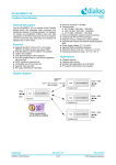
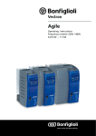
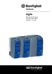
User Guide
196-02-C - DA7322 Audio Codec with DSP
UG-196-02-C
UG-196-02-C
196-02-C - DA7322 Audio Codec with DSP
Contents
Contents .................................................................................................................................... 2
1
Terms and definitions ........................................................................................................... 3
2
References ........................................................................................................................... 3
3
Introduction ......................................................................................................................... 4
4
Summary .............................................................................................................................. 5
5
Hardware ............................................................................................................................. 5
6
7
5.1
DA7322 EVB .......................................................................................................................... 6
5.2
Jumper and connector information ...................................................................................... 7
5.3
Power supplies ...................................................................................................................... 9
Power commander software ................................................................................................10
6.1
Installation .......................................................................................................................... 10
6.2
Power commander interface .............................................................................................. 12
6.3
Status and controls ............................................................................................................. 13
6.4
Register control Interface ................................................................................................... 15
Troubleshooting ..................................................................................................................16
7.1
Software issues ................................................................................................................... 16
7.1.1
7.2
Selecting USB playback ......................................................................................... 16
Hardware Issues .................................................................................................................. 17
7.2.1
MCLK select .......................................................................................................... 17
7.2.2
I2C configuration .................................................................................................. 18
7.2.3
SPI configuration .................................................................................................. 18
Appendix A Codec text files .......................................................................................................19
A.1
Information ......................................................................................................................... 19
A.2
Codec file commands .......................................................................................................... 19
Revision history .........................................................................................................................20
User guide UG-196-02-C
CFR0011-121-00 Rev 1
Revision 0.6
2 of 21
15-September-2014
© 2014 Dialog Semiconductor GmbH
UG-196-02-C
196-02-C - DA7322 Audio Codec with DSP
1
Terms and definitions
AIF
CLK
DIO
DMIC
DUT
DSP
ECM
EVB
GPIO
GUI
I2C/SPI
I2S
MCLK
OS
PCB
PDM
PSU
SPDIF
USB
2
Digital Audio Interface
Clock
Digital Input/Output
Digital Microphone
Device Under Test
Digital Signal Processor
Electret Condenser Microphone
Evaluation Board
General Purpose Input Output
Graphical User Interface
Inter-Integrated Circuit/Serial Peripheral Interface
Integrated Interchip Sound
Master Clock
Operating System
Printed Circuit Board
Pulse Density Modulation
Power Supply Unit
Sony Philips Digital Interface Format
Universal Serial Bus
References
1. UG-179-07-D, 179-07-D Digital IO board User Guide, Dialog Semiconductor
User guide UG-196-02-C
CFR0011-121-00 Rev 1
Revision 0.6
3 of 21
15-September-2014
© 2014 Dialog Semiconductor GmbH
UG-196-02-C
196-02-C - DA7322 Audio Codec with DSP
3
Introduction
The DA7322 Evaluation Board (EVB) has been designed to allow measurement and evaluation of
the DA7322 device. The EVB is supplied with a USB memory stick containing various documents
and software to allow you to control the DA7322.
The software is called Power Commander and uses a simple graphical user interface to allow you to
control the DA7322 via the USB port of a PC.
The EVB has a number of jumper links providing the flexibility to change the system configuration
and to allow the required measurements to be made.
HS_ GND_ OUT
RING2_ SENSE
AAD
SLEEVE_ SENSE
HP_L
3- or 4- pole and
polarity detection
plus Swap- Switch
Control
Key- Detect with
Auto- Mute
Headphone mono
/
stereo/ differential
and impedance
range detection
JACKDET
Sleeve Ring2
TRRS_ RING2
TRRS_ SLEEVE
HS_MIC_ OUT
MICBIAS1
MIC1_P
ADC
1
+
MIC4_N
-
MIC2_P
+
MIC2_N
-
MIC3_P
+
OUT3_N
DAC
4
MIC3 PGA
OUT3
OUT4_P
OUT4D
OUT4_N
ADC
3
-
OUT3_P
OUT3D
OUT3S
Digital Mix and Route
,
Acoustic Filtering,
Noise gate
ADC
2
MIC2 PGA
MIC3_PRE
MIC3_N
DAC
3
DRC/ Compressor/ Limiter,
Bass Boost
MIC2_PRE
MIC
GROUND CENTRED
OUTPUT AMPLIFIERS
Noise Suppression
,
Acoustic Echo
Cancellation,
MIC4_PRE
MIC
HP R
DAC
2
Beamforming
+
MIC1_PRE
MIC14 PGA
MIC4_P
HP_R
Asynchronous Sample
Rate Conversion
MICBIAS1
HP_L
HP L
OUT4S
OUT4
MIC
Line outputs for AV equipment/Sound bar
MIC1_N
DAC
1
DSP
DATOUT
HP_R
PDM1
PDM2
PDMCLK
MICBIAS 2
PLL
MICBIAS2
Dialog
MICVDD
SEMICONDUCTOR
CPF2_P
1µF
DA7322
Charge
Pump
22nF
CPF1_P
Charge
Pump
CPF2_N
DIGITAL AUDIO
INTERFACE
‘DAIB’
DIGITAL AUDIO
INTERFACE
‘DAIA’
Primary SPI/I2C
INTERFACE
AUDIO
DIGITAL AUDIO
INTERFACE
‘DAIC’
1µF
CPF1_N
OPVSS
VCM
INT
1µF
DACREF
GND
1µF
WDT
VDD
IOVDD
AOVDD
WCLK_C/JTAG3/GPIO3
DATIN_C/JTAG4/GPIO4
DATOUT _C/JTAG2/GPIO2
DATIN_B
BCLK_C/JTAG1/GPIO1
WCLK_B
BCLK_B
DATOUT_B
WCLK_A
DATIN_A
BCLK_A
DATOUT_A
MCLK
nRST
SO
CS
SCL
SDA
1µF
Figure 1: DA7322 Block diagram
User guide UG-196-02-C
CFR0011-121-00 Rev 1
Revision 0.6
4 of 21
15-September-2014
© 2014 Dialog Semiconductor GmbH
UG-196-02-C
196-02-C - DA7322 Audio Codec with DSP
4
Summary
This document provides information about the EVB and Power commander software to allow testing
and evaluation of the DA7322 Audio Codec with DSP.
The hardware solution is based upon two PCBs:
● Digital IO Board - 179-07-D (see References section)
● DA7322 Evaluation board - 196-02-C
Power Commander requires a PC operating Windows 2000/XP/Vista/Windows 7 with a USB
interface.
To run Power Commander under Windows Vista, set the default installation location to ‘C:\Dialog
Semiconductor\’.
Power Commander allows you to:
● Configure the DA7322 using one of the several pre-loaded initialisation files (i.e. start-up
sequences)
● Read and write to all control registers
● Monitor the device status
Note 1
5
Dialog recommends connecting the EVB+digital IO board to a 500 mA capable USB port as we cannot
guarantee that a USB hub (set to 100 mA) is sufficient to operate it correctly. When using the on board
class D amplifiers, an external supply must be used to provide sufficient power to operate the high
power speaker drivers on the EVB.
Hardware
The DA7322 EVB platform consists of two boards that connect together. The first board is the EVB
containing the DA7322 device and essential external components. This board can also be used as a
standalone board or as a module for a customer development platform provided the essential
supplies and inputs are correctly connected to the board.
The second board is the Digital IO board which provides the required power and USB control
interface to the DA7322 EVB to allow signals to be easily connected and configured into the DA7322
device. The digital IO board is referenced in a separate document (UG-179-07-D) which explains the
various connections available and the jumper configurations for the board.
User guide UG-196-02-C
CFR0011-121-00 Rev 1
Revision 0.6
5 of 21
15-September-2014
© 2014 Dialog Semiconductor GmbH
UG-196-02-C
196-02-C - DA7322 Audio Codec with DSP
5.1
DA7322 EVB
The DA7322 EVB (196-02-C) contains the DA7322 and associated components, configuration
pins/jumpers, input/output connectors and measurement points for flexible configuration and access
to the DA7322. It includes:
●
●
●
●
4 x 3.5mm analogue microphone sockets
2 x 3.5mm differential lineout sockets
1 x 3.5mm single ended lineout socket
1 x 3.5mm Headphone jack (supporting 3 and 4 pole jacks)
The board and default jumper setting are shown in Figure 2 and a description of the individual
jumpers are shown in Table 1.
Figure 2: EVB default jumper settings
User guide UG-196-02-C
CFR0011-121-00 Rev 1
Revision 0.6
6 of 21
15-September-2014
© 2014 Dialog Semiconductor GmbH
UG-196-02-C
196-02-C - DA7322 Audio Codec with DSP
5.2 Jumper and connector information
Table 1: 196-02-C Jumpers link positions and connectors
Reference Designator
Position/pins
Function
J1
3.5mm connector for MIC 1 input
J2
3.5mm connector for MIC 2 input
J3
3.5mm connector for MIC 3 input
J4
3.5mm connector for MIC 4 input
J5
Pin 1: +
Pin 2: -
Differential P/N MIC1 input
J6
Pin 1: +
Pin 2: -
Differential P/N MIC2 input
J7
Pin 1: +
Pin 2: -
Differential P/N MIC3 input
J8
Pin 1: +
Pin 2: -
Differential P/N MIC4 input
J9
J10
J11
J12
J13
J14
User guide UG-196-02-C
CFR0011-121-00 Rev 1
Short 1-2
MIC1 -VE input pulled to GND with 2.2kΩ for two wire ECM
configuration
Short 2-3
MIC1 -VE input shorted to GND for single ended microphone
input configuration
No Jumper
(default)
MIC1 -VE input pulled to GND with 47kΩ for differential ECM
microphone input configuration
Short 1-2
MIC2 -VE input pulled to GND with 2.2kΩ for two wire ECM
configuration
Short 2-3
MIC2 -VE input shorted to GND for single ended microphone
input configuration
No Jumper
(default)
MIC2 -VE input pulled to GND with 47kΩ for differential ECM
microphone input configuration
Short 1-2
MIC3 -VE input pulled to GND with 2.2kΩ for two wire ECM
configuration
Short 2-3
MIC3 -VE input shorted to GND for single ended microphone
input configuration
No Jumper
(default)
MIC3 -VE input pulled to GND with 47kΩ for differential ECM
microphone input configuration
Short 1-2
MIC4 -VE input pulled to GND with 2.2kΩ for two wire ECM
configuration
Short 2-3
MIC4 -VE input shorted to GND for single ended microphone
input configuration
No Jumper
(default)
MIC4 -VE input pulled to GND with 47kΩ for differential ECM
microphone input configuration
Short 1-2
(default)
Connects MIC1_N to J30 (Headset) internally via chipset
Short 2-3
Connects MIC1_N to J1 (MIC1) connector
Short 1-2
(default)
Connects MIC1_P to J30 (Headset) internally via chipset
Short 2-3
Connects MIC1_P signal to J1 (MIC1) connector
Revision 0.6
7 of 21
15-September-2014
© 2014 Dialog Semiconductor GmbH
UG-196-02-C
196-02-C - DA7322 Audio Codec with DSP
J15
Short 1-2
Selects MICBIAS1 output to supply MIC 2/3/4 bias voltages
Short 2-3
(default)
Selects MICBIAS2 output to supply MIC 2/3/4 bias voltages
J16
Pin 1: +
Pin 2: -
Differential OUT4 P/N output
J17
Sleeve: GND
Ring: OUT4_N
Tip: OUT4_P
3.5mm socket for differential OUT4
J18
Short 1-2
(default)
Connects 1V6_DIO supply (from digital IO) to VDD_DUT
supply input (EVB), This link can be replaced with an ammeter
for current monitoring
Pin:3
GND connection for connecting external supply between Pin 2
(1V6 supply to part) and Pin 3 GND
J19
Short 1-2
(default)
Jumper to break out 1V6 supply connection and VDD for
current monitoring or external supply
J20
Short 1-2
(default)
Jumper to break out AOVDD supply connection for current
monitoring or external supply
J21
Pin 1: +
Pin 2: -
Differential OUT3 P/N output
J22
Sleeve: GND
Ring: OUT3_N
Tip: OUT3_P
3.5mm socket for differential OUT3
J23
SCL isolation jumper – see
Table 2
J24
SDA isolation jumper - see
Table 2
J25
J26
Short 1-2
(default)
Connects IOVDD_DIO supply (from digital IO) to IOVDD_DUT
supply input (EVB), This link can be replaced with an ammeter
for current monitoring
Pin:3
GND connection for connecting external supply between Pin 2
(IOVDD supply to part) and Pin 3 GND
Sleeve: GND
Ring:OUT4_SE
Tip: OUT3_SE
3.5mm socket for OUT3/4 single ended output
J27
J28
100 pin connector to digital IO board
Short 1-2
Inserts a 16Ω load across the right headphone output for test
purposes
Short 2-3
Inserts a 32Ω load across the right headphone output for test
purposes
J29
For internal use only
J30
3.5mm headphone socket supporting 3 and 4 pole jacks
J31
For internal use only
J32
User guide UG-196-02-C
CFR0011-121-00 Rev 1
Short 1-2
Inserts a 16Ω load across the left headphone output for test
purposes
Revision 0.6
8 of 21
15-September-2014
© 2014 Dialog Semiconductor GmbH
UG-196-02-C
196-02-C - DA7322 Audio Codec with DSP
Short 2-3
J33
Inserts a 32Ω load across the left headphone output for test
purposes
Pin:1
External supply connection point for SPK_VDD supply, used
by class D amplifiers.
Pin:2
GND connection for connecting external supply between Pin 1
(SPK_VDD supply to class D amplifiers) and Pin 2 GND
J34
Speaker A output connector from class D speaker output
J35
Speaker B output connector from class D speaker output
5.3 Power supplies
The DA7322 EVB is connected to the digital IO board via the large 100 pin connector (J27) which
allows the boards to mate together, The boards are powered when a USB cable is connected to J1
(+5V_USB) on the digital IO board.
Using the default jumper settings (J18, J19, J20 and J25 on EVB) shown in Figure 3, the DA7322
device on the EVB is powered from the supplies on the digital IO board. The two supplies used from
the digital IO board are 1V6_DIO (supply for VDD) and IOVDD_DIO (supply for IOVDD & AOVDD).
The IO supply is user selectable on the digital IO board depending on what IO voltage is required.
SPK_VDD to power
on board class D
amplifiers
VDD to device
AOVDD to device
100 pin EVB connector,
power originates from
Digital IO board
IOVDD to device
Figure 3: DA7322 supplies and connections on EVB
The DA7322 EVB allows external supplies to power the board by removing J18 and J25 jumpers.
Supplying power to Pin 2 and ground on Pin 3 of J18 and J25 allows the board to be powered
independently of the digital IO board. Current measurements on individual supplies can also be
performed by connecting an ammeter between the supply and Pin 2 of the jumper when using an
external supply. Current can also be measured by connecting an ammeter across pins 1 and 2 if
using the on board digital IO board regulators to power the board.
All power to the on-board digital IO regulators are supplied from +5V on the USB connector (normally
limited to 500mA maximum). The supply for the on-board class D amplifiers of the EVB can be
supplied from this +5V USB supply through SP7 but this is not recommended. The jumper J33 gives
the ability to power the on-board class D amplifiers from an external +5V power source as these can
draw high current when driven at full power. It is recommended that an external supply is used in this
way whenever the class D amplifiers are used.
Note 2
When using ammeters to measure the current to the device, ensure that any voltage drop across the
ammeter is accounted for so that the supply voltage reaching the device is at a sufficient level. Adding
User guide UG-196-02-C
CFR0011-121-00 Rev 1
Revision 0.6
9 of 21
15-September-2014
© 2014 Dialog Semiconductor GmbH
UG-196-02-C
196-02-C - DA7322 Audio Codec with DSP
extra impedance in the supply lines such as ammeters can also reduce the performance of the device
under test.
6
Power commander software
6.1 Installation
Using the USB memory stick provided with the EVB kit, run the ‘setup.exe’ file (USB\Power
commander\setup.exe).
Click ‘Next>>’
User guide UG-196-02-C
CFR0011-121-00 Rev 1
Revision 0.6
10 of 21
15-September-2014
© 2014 Dialog Semiconductor GmbH
UG-196-02-C
196-02-C - DA7322 Audio Codec with DSP
Select ‘ I accept the licence Agreement.’ then Click ‘Next>>’
Click ‘Next>>’ and wait for files to install
Click ‘Finish’
You may need to restart your computer. In this case a pop up window will appear asking you to do
so.
Once the software is installed, plug the USB cable into the Digital IO board which must also be
connected to the EVB through the large 100 pin connector of each board. Windows should detect the
User guide UG-196-02-C
CFR0011-121-00 Rev 1
Revision 0.6
11 of 21
15-September-2014
© 2014 Dialog Semiconductor GmbH
UG-196-02-C
196-02-C - DA7322 Audio Codec with DSP
USB device and automatically install the driver. If not, the driver is included on the USB stick supplied
with the EVB kit.
6.2 Power commander interface
Run the DA7322/3 Power commander software by clicking the shortcut on the appropriate item in the
Start menu (All Programs>Dialog Semiconductor>Audio>). The screen shown in Figure 4 will
appear.
The best setting for the PC display size is 1024x768 pixels or above. Font size on the PC display
should be Normal (95dpi). It is important to note that a display size other than the recommended
setting will affect the way in which the panels appear.
To start the device, plug in the USB cable to the digital IO board.
Figure 4: Initial interface
The [USB OK?] LED should illuminate steady green if the USB interface is correctly connected and
operational. If the [USB OK?] LED is blinking and yellow, it indicates that the device is not yet
communicating via the I2C interface. See the Troubleshooting section of this document for more
details.
User guide UG-196-02-C
CFR0011-121-00 Rev 1
Revision 0.6
12 of 21
15-September-2014
© 2014 Dialog Semiconductor GmbH
UG-196-02-C
196-02-C - DA7322 Audio Codec with DSP
6.3 Status and controls
● Polling Enabled
By default the current page of device
register content is updated via polling the I2C interface. If
disabled, these read-backs are suppressed. This is used to
force the communication over the bus to be silent. If this is set
to automatic, the program will only poll the device while the
application is the topmost window. If obscured by another
program or window, polling will be disabled.
● LED
If the device is active this LED is green. If
the LED is red the device is inactive
● Interface
Selects between SAM3U I2C/SPI control and
offline mode. Switching to offline, then back to SAM3U
I2C/SPI reinitialises the USB interface. I2C mode is the default
communication setup for the device
● USB OK? Solid green illumination indicates that the USB is
OK and communicating.
● Stop Program
This terminates the program. If there are
unsaved changes, a dialog box is displayed.
● Read Chip ID
This reads the Chip ID from the device
and displays the content in the text box above the button. The
text box indicates the device version when the device is
active. When inactive, version status will not be correct.
● Load
Loads previously saved text files, sends loaded
register values in file and reads back all registers from device.
Selecting ‘Load’ opens a list of other options related to loading
files. Select ‘load codec file ..’ to bring up a dialog box which
allows you to select, view, copy or re-name files. Once a file
has been selected, ‘Load codec file..’ opens the file and
executes commands listed in the file to manipulate the
registers of the device allowing the device to be quickly
configured for different setups with a script file. Load codec file
should always be used when using audio based devices, Load
is used for non-audio based device configuration.
● Save
Saves the current panel state to a text file.
Selecting ‘Save Codec file..’ saves the codec registers in a
text file with sequential register address number, value of
register and name listed in the file. Selecting ‘Register Dump’
option saves the current register values to a text file in a
slightly different format, the register name and value of
register are shown in the file content. See Appendix A for
further details. Save Codec should be used when using audio
based devices.
Note 3
User guide UG-196-02-C
CFR0011-121-00 Rev 1
The difference between ‘Save’ and ‘Register Dump’ is that the
‘Save’ option dumps the contents of all panel controls to the file
(a save state operation); whereas, ‘Register Dump’ reads the
device contents (including status registers) into the file. Also
some codec registers do not have read-back capability.
Revision 0.6
13 of 21
15-September-2014
© 2014 Dialog Semiconductor GmbH
UG-196-02-C
196-02-C - DA7322 Audio Codec with DSP
● Slave Address
Sets the slave address of the device. This
affects all I2C/SPI communication. The codec slave address
for DA7322 is 0x34 and this is the 8bit value (34h for Write,
35h for Read).
● Find
Finds the register address location entered into
the ‘Reg. address’ field control of the GUI and highlights the
location of the register if found.
● Send
Sends a single byte of data to the device using
the Slave Address, Reg. Address and Data to Send.
● Read
Reads a single byte of data from the device using
the Slave and Reg. Address.
● Find
Finds a control matching a full or partial register
name, a control bit name, or a register number (e.g. R23 or
17h). Pressing ‘Find’ repetitively will step through all matching
items.
Note 4
1
2
3
4
User guide UG-196-02-C
CFR0011-121-00 Rev 1
5
If the Device Address does not match the port numbers on the
device, this can be used to control/read any other device on the
I2C/SPI bus.
1. Synchronise Panel from Device Reads all the register
contents of the device and updates the panel to match.
2. Synchronise Device from Panel Writes all the device
registers to match the panel. (Refresh operation)
3. Reload Configuration
Resets registers to values
specified in configuration file for the PMIC section and default
values for the codec.
4. Clear all I2C read-back indicators Sets all read-back
indicators to 0.
5. Read All Registers
Reads all registers,
comparing with the panel controls.
Revision 0.6
14 of 21
15-September-2014
© 2014 Dialog Semiconductor GmbH
UG-196-02-C
196-02-C - DA7322 Audio Codec with DSP
6.4 Register control Interface
The control interface has a series of coloured tabs along the top of the interface. These are used to
select a group of registers for different areas of the device. The tabs available along the top of the
interface are Config, Mic Input, HP/Line Output, Out Filter, In Filter, DAI, ACC, Outputs, ALC, Clock
Ctrl, DSP Ctrl and DA7323 as shown in Figure 5.
Each tab can be selected by left clicking on the tab. A register cluster is then displayed below for the
associated tab. These consist of a mixture of Boolean toggle buttons, multi-value ring controls, or
slide controls, as well as a hexadecimal read-back indicators showing the total equivalent register
value and a read-back indicator showing the current register value. The Event Register is labeled
with a register number in decimal and its hexadecimal equivalent.
The read-back indicator readings can be switched individually to decimal, octal, hexadecimal or
binary by clicking on the ‘x’, or they may all be changed at once between hexadecimal and binary
using the ‘Settings>Binary Indicators’ menu item.
Tabs to select a
page of registers
relating to the tab
title name
Hexadecimal value of
the buttons selected
for the register
Decimal value of
register number
Hexadecimal value of
register number
Read-back value of register contents
Normally in hexadecimal but can be
changed by clicking on the read-back
indicator selector button
‘x’ - Read-back
indicator selector
Figure 5: Tabs and read-back indicator
User guide UG-196-02-C
CFR0011-121-00 Rev 1
Revision 0.6
15 of 21
15-September-2014
© 2014 Dialog Semiconductor GmbH
UG-196-02-C
196-02-C - DA7322 Audio Codec with DSP
7
Troubleshooting
This section is an aid to resolving problems occurring in the previous sections.
7.1 Software issues
The USB device should install without difficulty automatically. Make sure that the installation finds
and uses the driver contained in the USB memory stick.
If the program is started before the USB Interface board is plugged in, the program interface button
will default to ‘SAM3U I2C (not present)’mode. If a board is subsequently attached and not detected,
try to move the interface control button to ‘offline’ mode then to ‘SAM3U I2C’ for the board to be
detected. If this is not successful make sure the USB is connected, then close and restart the
program.
If communications are lost during use of the device, switching the ‘Interface mode’ to Offline, then
back to SAM3U I2C will reinitialise the USB interface. If this does not work, unplug the USB cable
and then reconnect. The software will detect this and reinitialise.
The software has been optimised for a display screen size of 1024 by 768 pixels or greater, with
Fonts set to Normal (96dpi). Unpredictable display effects can occur when large fonts (120dpi) are
used. To resolve this issue and set the font size to normal in the operating system by right-clicking on
the desktop, select Properties. Select the Settings tab, then Advanced, and finally Normal size from
the drop-down box (This sequence is dependent on which operating system is being used).
7.1.1
Selecting USB playback
The Dialog DA7322 EVB platform allows a number of audio sources to be selected with ease for
testing and evaluation. One example is to stream audio from a PC to the EVB over the USB
interface, this can easily be done in the following way.
Right click on speaker symbol in task bar, circled in red
Select playback devices
User guide UG-196-02-C
CFR0011-121-00 Rev 1
Revision 0.6
16 of 21
15-September-2014
© 2014 Dialog Semiconductor GmbH
UG-196-02-C
196-02-C - DA7322 Audio Codec with DSP
Left click on Dialog US-Lab IO, select ‘Set Default’ then OK.
Audio played on the PC will now be streamed over USB to the digital IO board for use on the
DA7322 board.
7.2 Hardware Issues
The most common hardware issue is caused by not selecting the correct jumper configuration for the
desired use case.
Carefully check jumper positions by comparing them with the default positions in Figure 2 and Table
1. Use the jumper table details and the board schematic as a guide to the jumper functions and
locations.
7.2.1
MCLK select
When moving to/from SPDIF/USB audio, ensure the correct MCLK source is selected with J16 on the
digital IO board. If the incorrect MCLK source is selected, the correct operation cannot be guaranteed
and the audio quality may be affected.
User guide UG-196-02-C
CFR0011-121-00 Rev 1
Revision 0.6
17 of 21
15-September-2014
© 2014 Dialog Semiconductor GmbH
UG-196-02-C
196-02-C - DA7322 Audio Codec with DSP
7.2.2
I2C configuration
When using I2C mode, ensure jumpers J23 and J24 are fitted on the EVB. On the digital IO board
ensure jumpers J14, 17-18 and 19-20 fitted and jumpers J14, 7-8, 9-10 and 11-12 are removed when
in I2C mode is required. See
Table 2 for I2C jumper configuration selection.
The codec slave address for DA7322 is 0x34 and this is the 8bit value (34h for Write, 35h for Read).
7.2.3
SPI configuration
When using SPI mode, ensure jumpers J23 and J24 are removed on the EVB. On the digital IO
board, ensure jumper links on J14, 17-18 and 19-20 are removed and jumpers J14, 7-8, 9-10 and 1112 are fitted when SPI mode is required. See
Table 2 for SPI jumper configuration selection.
When reading/writing to registers in SPI mode, ensure the correct page mode is selected for the
paging area selected (register base address 0x00, 0x80 – see DA7322 data sheet).
Table 2: I2C/SPI jumper configuration information
I2C mode selection, Jumper selection
SPI mode selection, Jumper selection
Digital IO board
Evaluation board
Digital IO board
Evaluation board
J14 - Jumper link 17-18
Fit J23
J14 - Remove link 17-18
Remove J23
J14 - Jumper link 19-20
Fit J24
J14 - Remove link 19-20
Remove J24
J14 - Remove link 7-8
J14 - Jumper link 7-8
J14 - Remove link 9-10
J14 - Jumper link 9-10
J14 - Remove link 11-12
J14 - Jumper link 11-12
User guide UG-196-02-C
CFR0011-121-00 Rev 1
Revision 0.6
18 of 21
15-September-2014
© 2014 Dialog Semiconductor GmbH
UG-196-02-C
196-02-C - DA7322 Audio Codec with DSP
Appendix A Codec text files
A.1
Information
The software includes the ability to save and load a codec text file containing command codes
representing the register addresses and data. This file is principally used to save and load setup
data, but may also be used to perform a small degree of automation. The text files are saved and
loaded via the buttons, ‘Load>load Codec file..’ and ‘Save> Save Codec file..’. The file format type is
’.TXT’, this can be edited and loaded in any standard text editor software.
The use of the Save\logtest.txt facility permits register contents to be transferred to the user’s own
software. Clicking on Save\logtest.txt allows the user to save a Register dump of the entire device
register map and data contents to file for reference or for use in other software.
Example message box
A.2
Codec file commands
The following formats are used for both read and write in the text file.
● Numbers apart from time delays are always expressed in Hex, separated by tabs. The use of ‘0x’
in front of the hex value is optional.
● The first parameter is the device register address in 8bit format. OR
o
The first parameter is a token:
o
●
●
●
●
‘DELAY’ or ‘WAIT’ will implement a time delay specified up to 65535 ms. The delay
time is specified in decimal or hex if preceded by ‘0x’
The second parameter is the data.
Comments (that is lines beginning with ‘//’) are permitted in the file.
Inline comments (that is //comment) are permitted.
The data will be processed in the order written and written directly to the specified device. The
screen controls will be updated once the commands in the file been processed.
User guide UG-196-02-C
CFR0011-121-00 Rev 1
Revision 0.6
19 of 21
15-September-2014
© 2014 Dialog Semiconductor GmbH
UG-196-02-C
196-02-C - DA7322 Audio Codec with DSP
Example file contents
//Write to CODEC
0x09 0xB1
1F 00
// Writes B1h to register 09h on codec slave address
// Writes 00h to register 1Fh on codec slave address
//Wait 255ms
DELAY 255
WAIT 0xFF
Revision history
Revision
Date
Description
0.1
02-Apr-2014
Initial version.
0.2
15-Apr-2014
Updated draft version
0.3
19-May-2014
Updated draft version
0.4
28-Jun-2014
Updated draft version
0.5
29-Jul-2014
Updated draft version
0.6
15-Sept-2014
Updated draft version
User guide UG-196-02-C
CFR0011-121-00 Rev 1
Revision 0.6
20 of 21
15-September-2014
© 2014 Dialog Semiconductor GmbH
UG-196-02-C
196-02-C - DA7322 Audio Codec with DSP
Status definitions
Status
Definition
DRAFT
The content of this document is under review and subject to formal approval, which may result in
modifications or additions.
APPROVED
or unmarked
The content of this document has been approved for publication.
Disclaimer
Information in this document is believed to be accurate and reliable. However, Dialog Semiconductor does not give any
representations or warranties, expressed or implied, as to the accuracy or completeness of such information. Dialog
Semiconductor furthermore takes no responsibility whatsoever for the content in this document if provided by any information
source outside of Dialog Semiconductor.
Dialog Semiconductor reserves the right to change without notice the information published in this document, including without
limitation the specification and the design of the related semiconductor products, software and applications.
Applications, software, and semiconductor products described in this document are for illustrative purposes only. Dialog
Semiconductor makes no representation or warranty that such applications, software and semiconductor products will be
suitable for the specified use without further testing or modification. Unless otherwise agreed in writing, such testing or
modification is the sole responsibility of the customer and Dialog Semiconductor excludes all liability in this respect.
Customer notes that nothing in this document may be construed as a license for customer to use the Dialog Semiconductor
products, software and applications referred to in this document. Such license must be separately sought by customer with
Dialog Semiconductor.
All use of Dialog Semiconductor products, software and applications referred to in this document are subject to Dialog
Semiconductor’s Standard Terms and Conditions of Sale, unless otherwise stated.
© Dialog Semiconductor GmbH. All rights reserved.
RoHS Compliance
Dialog Semiconductor complies to European Directive 2001/95/EC and from 2 January 2013 onwards to European Directive
2011/65/EU concerning Restriction of Hazardous Substances (RoHS/RoHS2).
Dialog Semiconductor’s statement on RoHS can be found on the customer portal https://support.diasemi.com/. RoHS
certificates from our suppliers are available on request.
Contacting Dialog Semiconductor
Germany Headquarters
Dialog Semiconductor GmbH
Phone: +49 7021 805-0
North America
Dialog Semiconductor Inc.
Phone: +1 408 845 8500
Singapore
Dialog Semiconductor Singapore
Phone: +65 64 849929
United Kingdom
Dialog Semiconductor (UK) Ltd
Phone: +44 1793 757700
Japan
Dialog Semiconductor K. K.
Phone: +81 3 5425 4567
China
Dialog Semiconductor China
Phone: +86 21 5178 2561
The Netherlands
Dialog Semiconductor B.V.
Phone: +31 73 640 8822
Taiwan
Dialog Semiconductor Taiwan
Phone: +886 281 786 222
Korea
Dialog Semiconductor Korea
Phone: +82 2 3469 8291
Email:
[email protected]
Web site:
www.dialog-semiconductor.com
User guide UG-196-02-C
CFR0011-121-00 Rev 1
Revision 0.6
21 of 21
15-September-2014
© 2014 Dialog Semiconductor GmbH