1
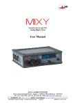
4MinX Portable, stereo, M/S Mixer/Recorder With analog and digital I/O User Manual AETA AUDIO SYSTEMS 18-22, avenue Edouard Herriot – Kepler 4 – 92350 Le Plessis Robinson – FRANCE Tél. +33 1 41 36 12 00 – Fax +33 1 41 36 12 69 – Web: http://www.aeta-audio.com 55 000 061 - B 4MinX - User Manual Specifications subject to change – All rights reserved by AAS May 11 55000061B_4MinX_gb.doc Table of contents 1. 2. Main technical characteristics ...........................................2 Functions .............................................................................4 2.1. Audio inputs ........................................................................................ 4 2.2. AES digital input ................................................................................. 8 2.3. Audio outputs ...................................................................................... 9 2.4. Monitoring ......................................................................................... 10 2.5. Internal alignment signal generator ................................................... 12 2.6. Intercom / Slate microphone .............................................................. 13 2.7. Power supply ..................................................................................... 13 3. Operating mode – Detailed description ..........................15 3.1. Switching on and off .......................................................................... 15 3.2. General principles and Menu structure .............................................. 15 3.3. Menu structure ................................................................................... 16 3.4. « Audio »Menu .................................................................................. 17 3.5. « Recording » menu ........................................................................... 19 3.6. « Settings » menu............................................................................... 22 3.7. « Tools » menu .................................................................................. 23 3.8. Audio user interface management ..................................................... 24 3.9. File reading ........................................................................................ 25 3.10. Short-cuts ......................................................................................... 26 3.11. ................................................... 27 4. Technical specifications....................................................30 4.1. Microphone/Line inputs ..................................................................... 30 4.1. AES inputs ......................................................................................... 31 4.2. Entrées AES ....................................................................................... 31 4.3. "Line Out" balanced analog outputs .................................................. 32 4.4. "Auxiliary Out" unbalanced analog outputs ...................................... 33 4.5. Digital Outputs .................................................................................. 33 4.6. Headphone output .............................................................................. 35 4.7. "Direct I/O" Interface......................................................................... 35 55 000 061 - B 4MinX - User Manual 4.8. "EXT I/O": Interface for RF transmitters/receivers ............................ 36 4.9. External DC supply ............................................................................ 37 4.10. Dimensions and weight .................................................................... 38 4.11. Environmental .................................................................................. 38 4.12. Versions - Options ............................................................................ 38 5. Annexes ............................................................................. 39 5.1. Overview of front panel elements ..................................................... 39 5.2. Input block diagram............................................................................ 37 5.3. Processing block diagram ................................................................... 38 5.4. Output block diagram ......................................................................... 39 5.5. Level maps ......................................................................................... 40 5.6. Filters.................................................................................................. 40 5.7. Limiter ................................................................................................ 42 5.8. Accessories ......................................................................................... 43 4MinX - User Manual 55 000 061 - B Introduction 4MINX is a portable mixer-recorder specially designed for outside multi-tracks recording (ENG). Totally new and innovative in terms of design, it is both a traditional mixer and multi-tracks recorder but also enables specific audio digital processing in real time.. 4MINX is ideally suitable for production, thanks to its outstanding audio characteristics and full compatibility with “M/S” and “surround” systems. 4MINX includes four Mic/Line inputs, with comprehensive powering (2 digital AES3 inputs with phantom power 10V for digital mic as per AES42 standard) and limiting features. 4MinX has various outputs: 6 analog and 6 digital via AES3 interfaces. It offers a great flexibility in terms of routing, whatever inputs or outputs.. The Recording module enables to record up to 8 tracks on different storage means. The unit integrates a project management system which allows multiples sound takes without any problem. 4MinX offers a nice keypad as well as a high quality TFT display for an easy and clear understanding user interface. 4Minx gives the user the opportunity to reconfigure the mixer management part as per his wishes or needs. 55 000 061 – B 4MinX- User Manual 1 1. Main technical characteristics 2 Light weight and small dimensions (1.9 kg, 260 x 75 x 195 mm) 4 Mic/Line transformerless inputs, very low noise (-128 dBu EIN) Adjustable input gain, 10 dB steps, from 0 to +50 dB Selectable high-pass filters on each channel Maximum overall gain: 90 dB, useful for dynamic and ribbon microphones Maximum input level: +19 dBu, without pad Input headroom: 40 dB, independent of input stage gain LED for overload warning on each input channel Fast limiter on each input, 40 dB operating range, with LED indicator Couplage stéréo ou M/S sur les entrées 1&2 et 3&4 Stereo M/S encoder/decoder on inputs 1 and 2, inputs 3 and 4 2 return or auxiliary line inputs, maximum acceptable level adjustable from -10 dBu to +22 dBu 2 separate Stereo M/S encoders/decoders, for monitoring and analog outputs. 4 balanced main outputs, maximum level adjustable from 10 dBu to +22 dBu 2 unbalanced outputs (level 6 dB below the balanced outputs) 3” QVGA TFT screen with adjustable brightness, displaying large scale bargraphs (50 dB dynamic range) High performance headphone amplifier, with selectable source and listening mode. Long operating time on Li-Ion DV battery with internal charger. AES digital outputs, stereo, 24 bits sample rates to 96 kHz 4MinX - User Manual 55 000 061 - B 55 000 061 – B AES3 digital inputs with phantom +10V for AES42 microphones 4MinX- User Manual 3 2. Functions The functions of the unit are shown on the functional diagrams that can be found in annex 5.2 & 5.2, “Input block diagram ” In paragraphs below, we will detail the different inputs and outputs of the 4MinX. 2.1. Audio inputs 2.1.1. “Mic/Line” inputs Each of these four inputs is available on a 3-pin female XLR socket, and is electronically balanced. They can offer 2 types of powering: Phantom 48V or Tonader 12V. If no powering is active, unbalancing an input has no negative impact on the performance. Each input has a gain level called a « fader ». Particularities: - Inputs 3 and 4 can also be fed from the “EXT I/O” socket, in which case no microphone powering is available. - Input 1 and 2 can stand very high audio levels thanks to a 20 dB attenuator. In such a case, the input can stand levels up to +39dBu. Functions of the “MIC/Line” inputs The following functions are available on each input, via a selection in the menu: 4 4MinX - User Manual 55 000 061 - B Nota: - Input stage gain setting, 0dB to +50dB, 10dB steps; Phantom power for a microphone, 48V, or “Tonader 12V” ; High-pass filtering, 50 Hz cut-off frequency, 18dB/octave; High-pass filtering, 300 Hz, 6dB/octave, suitable for compensating proximity effects in directional microphones; Polarity inversion (phase reversal) ; Fast limiting, with “soft knee”; Routing to Left or Right bus, or Center (i.e. L and R), with pan-pot, or not routed at all ; The “risk of overload” LED begins to light at 12 dB below peak PAD on channel 1 and 2 ; The 50Hz analog filter can be added to the digital filters. In this case, the slope is 32 dB /oct under the 50Hz. A limiter can be inserted into each channel. Its activation is shown by a green LED that turns red when the signal begins to limit. Stereo and MS Via menu selection, channels 1 and 2, 3 and 4 can be used as independent channels or coupled for stereo or M/S operation . When used as a couple of stereo or M/S channels, the odd-numbered channel becomes the master, controlling the level of both channels. The even-numbered channel provides +/-5dB adjustment of the balance in L/R mode (normal). In normal stereo mode, transducers usually have matching sensitivity; Any change of the input gain on one channel induces the same on the other channel; The even-numbered channel adjusts the balance between L and R channels ; by +/-6 dB 55 000 061 – B 4MinX- User Manual 5 The odd-numbered input is routed to the Left bus, while the evennumbered input is routed to the Right bus by convention Overriding this default routing is possible! But please pay attention to incoherencies in such a case! In “M/S” mode, transducers often have different sensitivity; The input gain adjustment is kept separate for odd and evennumbered channels; The outer control on the even-numbered channel adjusts the stereo image width; In the center detent position, a coherent couple stereo pair provides a normalised 110° mutual angle; Whenever inverting the phase of an even-numbered channel, after decoding from M/S to L/R the stereo image reveresed Manual routing is inhibited and the signals are routed and decoded as follows: odd-numbered input is the “M” signal, even-numbered input is the “S” signal; odd-numbered input + even-numbered input (M+S) is routed to the Left bus; odd-numbered input - even-numbered input (M-S) is routed to the Right bus Limiters A limiter can be inserted via the menu into each channel, after the channel fader. This is a fast limiter with a dynamic range wide enough to stand the 40 dB headroom of the input stage. As mentioned previously, activating the limiter is shown by an LED (green) which turns into red while in function. As long as the signal level stays below the limiter threshold, little effect is heard on the signal. When the limiter is triggered, its output stays 2 dB below the A/D converter clipping level for up to 40 dB input overdrive.. The threshold can be adjusted through the menu from –3dBFS to –12dBFS The -6dBfs value by default enable to stand the -40dB input overdrive without reaching the clipping level of the audio chain while keeping the dynamic for the useful signal. 6 4MinX - User Manual 55 000 061 - B It can thus be seen as a “safety” limiter, that may be left active all the time! Nota : In case of coupled channels, in stereo pair of in M/S mode, or even in mode 3 or 4 coupled inputs, each input gets the gain reduction command. This command corresponds to the stronger generated by the input and the closer to the clipping level. 2.1.2. Return / line inputs There are 2 Line inputs or Return channels on XLR 5 pins. The signals are electronically balanced and can be unbalanced with no impact on performance. The maximum output level (which corresponds to the maximum digital level, 0 dBFS) is adjustable via the menu from -10 dBu to +22 dBu. The inputs can be used as return channel input control from the camera but also as additional inputs to the buses or to the recorder. 2.1.3. “EXT I/O” socket, wireless transceivers The “EXT I/O” socket enables to connect devices to enlarge the number of inputs or outputs. This interface offers 2 balanced inputs (mic/line 3 and 4). A specific menu on the input 3 and 4 allows the user to select this interface in place of XLR 3 and 4. We remind you that on this interface 48V and T12 powering are not available for security reasons. All the other settings dedicated to these inputs are left available. For example the gain adjustment is possible between 0 and +50 dB for each of input 3 and 4 which allows users to set a suitable level for the link from the radio receivers to the mixer channels 3 and 4. 2 analog unbalanced outputs will also be found on this interface. More detailed information are available in paragraphs dedicated to outputs. Nota: You can power peripheric devices (9V/600mA) via this interface. 55 000 061 – B 4MinX- User Manual 7 2.2. AES digital input 4MinX can accept AES3 digital audio input on its « Dig. In » TA3 sockets. The signals can be routed or mixed in the bus or to other analog inputs. The input 1&2 can be used to synchronize the 4MinX to another machine. This feature can be set in the synchronization menu. It is necessary to specify in the same menu the frequency of the AES signal. Nota :The 2 AES inputs have a frequency converter which means that the inputs can be used in master mode or in other type of synchronisation. Nota : Don't forget to set the correct sample frequency on the synchronization menu when you want to use the AES input for synchronization 8 4MinX - User Manual 55 000 061 - B 2.3. Audio outputs 2.3.1. Main analog outputs The main analog outputs are in 2 pairs on XLR 5 connector. By the menu, you can select the source for each of the 4 outputs i.e different input sources, stereo mix down, others. The audio signals are balanced electronic signals. They can be unbalanced with no impact on performance as long as the level stays below +19 dBu. The maximum output level (which corresponds to the maximum digital level, 0 dBFS) is adjustable via the menu, from -10 dBu to +22 dBu, channel by channel. Also via the menu, a 40 dB attenuator can be inserted on each output channel, providing a “microphone level” signal. 2.3.2. Auxiliary analog ouputs Identical to those delivered by the XLR5M 1 / 2 , 2 channels asymmetric signals are fed to a stereo mini-jack 3.5 mm. Their level is 6 dB below those on the balanced main output 1 / 2 . Their typical use is for linking the mixer to a semi-professional recorder (MiniDisc, K7, DAT…) or connecting a second headphone. 2.3.3. Analog outputs for transceivers The L and R mix buses or any input can be output on the « EXT I/O » socket (on the left side of the unit), with a separate adjustment of the maximum level for each channel from -50 dBu to +14 dBu, which allows a suitable adaptation to most radio transceivers. The outputs are unbalanced. 2.3.4. Digital outputs By “settings” menu you can select, for 24bits digital signals, the « pro » mode or « consumer » mode depending on the devices to be connected. “AES” balanced signals in 110 Ohm are fed on mini XLR 3 (TA3). 55 000 061 – B 4MinX- User Manual 9 2.4. Monitoring The « Monitor » function allows the selection of signals inside 4MINX for displaying their level on the screen and monitoring them on headphones 2.4.1. Display The display screen of 4MINX is a 3” color QVGA TFT display. This technology features a very wide viewing angle and fast response time. The display brightness is adjustable. The main display shows the audio level of left and right signals at the bottom of the display, while you can see the the level of the four mixer channels right above them (after the channel faders but before routing to the mix buses). Those levels are displayed by 6 LED colored bargraphs. Levels are displayed on large scale bargraphs covering up to 60dB, in dBFS or VU . They are measured with fast PPM ballistics. In addition, peaks are held for about 1 second (“peak-hold” function). 4 colored thresholds can be defined (mini, nominal, yellow and red). Levels are measured with fast PPM ballistics. In addition, peaks are held on for about 1 second (“peak-hold” function). An “OVL” icon shows up whenever the level reaches -3 dBFS or more. 10 4MinX - User Manual 55 000 061 - B 2.4.2. Configuration The « Monitor » function allows the selection of signals inside 4MINX for displaying their level on the screen and monitoring them on headphones By pressing the Headphone key and moving the rotary, you can select the following signal sources for monitoring: All inputs 1, 2, 3, 4 post or pre-fader ( level adjustment) Channels couple, AES 1&2, AES 3&4 Return/Line ; L and R mix buses; … Nota : Selection can be attributed to one of the 4 programmable function keys ( F1 to F4) simply by pressing on it. A second menu can be reached via the Shift key and gives opportunity for 8 additional monitoring configurations Nota : By pressing twice on the headphone key you reach selection of sources and mode if keys are already programmed 55 000 061 – B 4MinX- User Manual 11 Nota: The headphone key enables to commute from listening to selecting sources mode.. 2.4.3. Headphone monitoring The headphone can be plugged into a stereo 6,35mm jack socket The monitor mode can be selected among the following: L/R : Normal stereo listening L/L: left signal on both ears , R/R: right signal on both ears , L+R : mono sum (L+R) on both ears; (useful for mono compatibility and phase coherence checking) M+S : M+S sum (normally left signal) on both ears , M-S : M-S sum (normally right signal) on both ears , M/S: listening of encoded signals (sum and difference) The L/RM/S matrixing is used for example to listen to a conventional stereo signal (L/R) when monitoring M/S microphones, or when monitoring outputs that have been M/S encoded. Alternatively, when the mixer is operated in normal stereo mode, encoding the signals for monitoring can be used to check the stereo correlation, by comparing the relative amplitude of the M and S signals. 2.5. Internal alignment signal generator An integrated oscillator can deliver a sinusoidal 1 kHz signal to the left channel and a 400Hz to the right channel. This can be used to align analog equipment connected to these outputs (note that peak meters are needed, as the signal is not a sine wave). The peak level of the generator is -18 dBFS (EBU digital reference level) by default but can be adjusted by menu from (-12 to -20 ). A function key can be set to have direct access to the feature. 12 4MinX - User Manual 55 000 061 - B 2.6. Intercom / Slate microphone A microphone is integrated into 4MINX‟s front panel and delivers an amplified signal replacing the normal audio signals c into the analog/digital outputs. A function key can be set to have a direct access to the feature. 2.7. Power supply 4MINX operates from a Li-Ion DV battery. The internal charger can recharge it from an external DC supply in less than 7 hours for a NPF960 (depending of the battery capability). The DC/Batt LED becomes red to show the proper operation of the internal charger (at the end of the charge.). If you don't want to charge the battery, you should use a dedicated power cable without connection on the Charger DC input pin (See connectors paragraphs), which might be needed if the external source is itself derived from a battery pack. 4MINX can operate from an external source of 8 V to 18 V DC.. 4MINX draws constant power from the external source when the voltage changes. But the voltage has to be superior to 10V for the charger. The switch from internal to external powering is automatic and produces no noise. Priority is always given to external powering. Icons on the screen indicate the level of the different voltage sources. The user can adjust the level of alarm on the external power source as well as on the DV battery by menu. When the level is reached, an alarm message appears on the display and icons turns into red. When battery level gets to 6.4V, 4MinX is automatically switched off. This prevents from any substantial damages on the battery. In such situation, the unit can only restart from a totally new charged or its external power supply. The consumption and thus the autonomy largely depends on the way the unit is used like the numbers of microphone and their powering, the level in the headphone, the level of the impedance in the headphone… 55 000 061 – B 4MinX- User Manual 13 Nevertheless, with a totally recharged battery, the autonomy is more than 7 hours (Sony NP-F960), with dynamic microphones or ribbon mic (without phantom power 48V) and with a 600 ohms headphone. In these conditions, 4MinX„s consumption is 500mA on an external 14.4V source. 14 4MinX - User Manual 55 000 061 - B 3. Operating mode – Detailed description 3.1. Switching on and off To turn 4Minx on, you hold the ESC button down for over > 2 seconds. The screen will light up and software is being downloaded. First appears the AAS logo and the green bar to show the download process on the right of the screen. To turn it off, use the « tools » menu / « power down ». This way of switch off the unit guarantees the user of the configuration settings saving. The audio projects information is saved on their side after each change. This “clean” way of switching off the unit gurantees the user a long life for the battery. Nota: You can turn 4Minx off by holding the Esc button for > 2 seconds. We advise to use this way as emergency procedure as it cannot save your latest modifications. 3.2. General principles and Menu structure To access 4MinX menus, hold briefly the “Esc” button.. the screen will light up and display the main menu of 4MinX. Generally speaking you can scroll down the menu by using the rotary control located on the right of the screen. Selecting or validating is activated by holding the Ok button or pressing the rotary control. To escape from selection and come back to previous menu, hold the Shift button down. To escape from selection and come back to monitoring mode, hold the ESC button down. In certain cases, the F1 and F2 button can be used as function keys in menus. 55 000 061 – B 4MinX- User Manual 15 3.3. Menu structure The menu is divided in 4 main parts: « Audio » Menu following sub-menus : « Audio Output » : outputs configuration « Mode » : Specific modes for inputs « Routing » : Output routing & bus mixing Recording « Audio input » : inputs configuration « Project management » « File management » : Sources management for recording « File Name format » : Files names management « Meta Data » : BWF files metadata writing « File format » : BWF files configuration « Pre-record » : pre-recording configuration « Record contact » Settings 16 « Synchro » : Sampling rate and mode configuration « Tone generator » : Tone generator configuration 4MinX - User Manual 55 000 061 - B « AES out mode » : AES output format configuration « Time code » : Time code smpte configuration « Display » : Bargraphs and brightness configuration « Function key » : F1 to F4 keys programming « Input mode » : note writing activation at the end of recording « Date » : change of the date in the system « Time » : change of the time of the system « Keyboard lock » : + and – keys locked after 10ms Tools « Power down » : Switch off key « Export configurations » : Export all project and machine configurations from SD card « Warning » : Battery alarm configurations, exteranl power supply and hard disk size « Disk format » : SD card format « Reset setting » : Delete all configurations « Import configurations » : Import all project and machine configurations from the SD card « Update » : update of the unit form the SD card About « Limiter Threshold » : Limiter threshold adjustment System information: version, IP adress Help 3.4. « Audio »Menu 3.4.1. « Audio Inputs »Menu - For each mic/line inputs from 1 to 4: 55 000 061 – B 4MinX- User Manual 17 The gain is adjustable by 10 dB steps from 0 to 50 dB The high pass filter 50Hz (50 Hz, 18dB/octave) can be turned on, Limiter can be turned on or off The phantom power can be set Off, on “P48” (phantom, 48V) or “T12” (Tonader, 12V) the channel polarity, “+” for normal operation, or inverted - For mic/line inputs 1 and 2 The PAD of 20dB can be turned on or off - For mic/line inputs 3 and 4 Input connector : XLR or Minicon - For line inputs 1 &2 ( return ) Maximum input level can be adjusted from -10dBu to +22dBu - For AES inputs 1&2 and 3&4 Phantom power 10V: Off or On as per AES42 standard 3.4.2. « Audio Output » menu - For line outputs 1 to 4 Maximum output level from -10dBu to +22dBu The PAD of 40dB to : On or Off - for I/O output 1&2 ( minicon ) 18 Maximum output level from -20dBu to +10dBu 4MinX - User Manual 55 000 061 - B 3.4.3. Mode menu In this menu, you can select different coupling mode for the mic/line inputs. There is no coupling programmed by default. On 2 inputs : Stereo mode, M/S mode Linked 1-2-3-4 Mode Linked 1-2-3 Mode corresponding to a double M/S system Decca tree 1-2-3 Mode (SOUNDFIELD option) 3.4.4. « Routing » menu Under this menu, you can set sources for the stereo mix down on one side and the AUX bus on the other side. Nota: The master does not have any impact on the Aux bus. A certain ratio is applied to the bus depending on the number of selected sources. You can also select for each analog or digital output its own source amongst inputs, buses and tracks. 3.5. « Recording » menu This menu takes care of managing the records during a shooting. Each shooting can be linked to a project, in which you can set “working days”. Each of the “working days” can be or not calendar days. For each record a time meter starts incrementing. We called it « Take ». Should you want to divide in « sub-group » each record, you can access to « scenes ». The difference with “takes” is that there is no automatic time meter. 55 000 061 – B 4MinX- User Manual 19 3.5.1. « Project Management » menu This menu enables you to create a new project (F1 button: « new project »), to download it (F4 button: « new project ») in place of another one. It manages also creating a new working day. You can visualise all the records already done in this project. You can create a new scene in the project at any time you want (F2: « new Scene »). The index for each scene is not linked to working days. It is defined independantly. You can withdraw a project for the list. In this case you will only destroy the information relative to the structure of the project. You won‟t loose the audio takes from the memory flash or other media support. You can navigate and scroll up and down the menu by using the rotary control as in the menu structure. When you activate the OK you can then escape from any structure menu. 3.5.2. File Management menu In this menu, you can configure your takes. This configuration is linked to the active project. We work in file. Each file can be mono, stereo or polyphonic (many mono tracks in the same file). The files are Wav with BWF extension and iXML fields. These types of files are compliant with any other classical Wav files. For each file you can select the sources as well as the media support. The sources numbers depend on the number of tracks authorised on your unit (see the “About “ menu) 20 4MinX - User Manual 55 000 061 - B To create or delete files, you use function keys. Once your configuration is set up you validate it by pressing the F4 button. Scrolling down the different lists is possible using the rotary control as in the menus. Pressing the Ok enables to enter or escape from the different fields. 3.5.3. « Filename format » menu By this menu you can change the root for the file names and have access to 3 fields. For each field, you can select information for the project like the name of the project, a scene name … The file will then have its name in the following way : [Field1]_[Field2]_[Field3]_[scene index]_[take index]_[file number] 3.5.4. «Meta data » menu In this menu you can enter a name for the active scene, notes on the current take, enter the name of the machine in the metadata as well as the name of the user. To write the data, you can connect a compact virtual keypad. Movements are via the rotary control and validation via the OK button 55 000 061 – B 4MinX- User Manual 21 3.5.5. «File format » menu In this menu you can specify the bit number of the SWF files, either 16 bits or 24 bits. 3.6. « Settings » menu 3.6.1. « Synchro » menu In the « mode » menu, you can select the Master mode (synch on the internal clock) or the external clock synch : AES or external clock (Time code Option) In the « Frequency » menu you can adjust the frequence : 32khz to 96khz Nota : It is mandatory to select similar sampling rate as of the external source synch to get a proper functionning of the unit. 3.6.2. « Tone » menu Enables to adjust the tone generator from -6 to-20dbFS 3.6.3. « Limiter Threshold » menu Enables to select the limiter threshold from -12dBFs to -3dBFs 3.6.4. « AES out mode » menu Enables to select « Professional » mode or « Consumer » mode for the AES streaming. 3.6.5. « Display » menu The « Brightness » menu deals with brightness for both the screen and the LEDs. The « Meter level » menu adjusts the threshold for each of the 4 LEDs level for the bargraphs. Those settings are the same than the ones used for the display of the TFT screen.and corresponds to the shreshold of 0dBvu to Vu. mode The « Bargraph » menu gives the opportunity to change the display mode of the audio levels on the screen from Vu mode to dBFS. In VU mode the 0db is on the yellow LED. 22 4MinX - User Manual 55 000 061 - B 3.6.6. Function key In this menu, you can configure the function keys in monitoring mode. You can program 2 functions for each key using the Shift key before the function key Here is a list of available functions: - For MIC/Line inputs o Gain, filters, phase, Limiter - Other functions o Slate, Tone,… 3.7. « Tools » menu 3.7.1. « Power down » menu It is mandatory to go through this menu to turn properly the unit off and avoid to loose information. 3.7.2. « Reset settings » By this function you can reset all audio settings of the machine to factory default. Note : It is thus mandatory to restart the unit 3.7.3. « configurations import/export » menu With these 2 menus, you import or export your projects and your machine settings on an SD card. Nota : After importing a configuration you need to restart the machine. 3.7.4. Warning You have 3 sub-menus to set up warning alarms for the DV battery, for the external power supply and for the space left on the media support 3.7.5. Media Support Format In this menu you can start a quick format of your SD card with FAT 32 file system. 3.7.6. Update To update your 4MinX starting from the SD card. 55 000 061 – B 4MinX- User Manual 23 3.8. Audio user interface management 5 6 4 3 2 7 8 1 9 10 1 : Icon to indicate that the + and – configuration buttons are locked 2 : Icon of the recording status: Stop, recording, Pause, read 3 : The actuallly selected function (colored button) => you can modify the parameter for each input by using the button + and -. 4 : Info on the synch mode and on the working sampling rate. 5 : Time code or system time 6 : info on the current scene or take number 7 : Project name and working day, can also be used to display alarm messages. 8 : Info on media support memory 9 : Info on the tracks number 10 : Status on the 4 main inputs for the selected parameter via function keys. 24 4MinX - User Manual 55 000 061 - B 3.9. File reading By pressing the « reading » key the « Player management » module appears and then you can select a project, a scene, or a take. The monitoring offers you a list of your tracks with the « listening » modes available. Forward and Rewind keys enables you to get to the right place in your file while reading it. 55 000 061 – B 4MinX- User Manual 25 3.10. Short-cuts To ease or optimise the use of your machine we made short-cuts by holding simultaneously 2 keys: Keys « Headphone» « Headphone » twice Function Display monitoring short-cuts Display monitoring selection « Stop » + « << » « Stop » + « >>» Delete last records, false take Creating new scene « Shift » + « OK » Inhibates or activates recording. Scrolling between the menu is via rotary control or via Ok key for the status commuting (if the icon is red, the file is recorded) Enables to change the display of media support information Access to the second function of the key « Shift » + « Esc » « Shift » + « Fx » 26 4MinX - User Manual 55 000 061 - B 3.11. coding In this chapter we will show examples of situations where LR M/S matrixing can be used, as well as possibilities offered by 4MinX. Many other configurations are possible. 3.11.1. Case n° 1: standard stereo engineering This is the most common application. In this case, mono microphones or normal (L/R) stereo microphone pairs are used. The output of the mixer is in standard stereo format. The L/R M/S matrixing is not needed in this case. However, L/RM/S matrixing may be used occasionally for monitoring, as a way of visually checking the stereo image coherence on the level meter display. If matrixing the monitored signal, the “left” bargraph shows the L+R sum, while the “right” bargraph shows the L-R difference. For common stereo production, the L-R level should be much lower than the L+R level, especially when mono compatibility is desired On the contrary, L-R level higher than L+R level would warn of a possible problem in sound pick-up (e.g. one microphone in a stereo pair is phase reversed). In this situation, the digital outputs all deliver signals in “classical” stereo mode. 3.11.2. Case n° 2: stereo recording using M/S microphones 55 000 061 – B 4MinX- User Manual 27 In this case, M/S stereo microphone pairs are used (typically the association of a directional cardioid transducer for the “M” channel and a bidirectional “figure of 8” transducer for the “S” channel), but the output of the mixer is in standard stereo format. Instead of left and right, the mixer buses now actually process M (Mid) and S (Side) signals. A similar matrixing is also needed for monitoring a normal stereo signal on the headphones (monitoring set in “M/S” position, visible on the screen by the indicator of M/S listening mode), except for monitoring the output “OUT” because it is already decoded to L/R format. . 28 4MinX - User Manual 55 000 061 - B 3.11.3. Case n°3: M/S recording using M/S microphones In this case, M/S stereo microphone pairs are used All the outputs, whatever analog or digital, deliver M/S format for recording. In this way, further stereo image processing is made possible with studio equipment in later production (analog or digital) The mixer buses process M (Mid) and S (Side) signals. Monitoring is here set in “M/S” mode, as matrixing is needed for monitoring a normal stereo signal on the headphones and meters. (On the screen, M/S listening mode). 55 000 061 – B 4MinX- User Manual 29 4. Technical specifications 4.1. Microphone/Line inputs Number 4 Format Balanced, without transformers Socket Female 3-pin XLR Microphone powering modes "Phantom", 48 V "Tonader" T12 V Maximum input level (1 and 2 , with "Pad") +39 dBu Maximum input level (3 and 4) +19 dBu Input headroom 40 dB Input stage gain (menu setting) 0 à 50 dB, par pas de 10 dB Equivalent input noise (EIN) (Gin = 50 dB) -128 dBu (200 , 22 Hz - 22 kHz) Maximum gain, analog in to out 90 dB Bandwidth 10 Hz - 50 kHz (+0 dB, -1 dB) Common Mode Rejection 90 dB @ 1 kHz Mic Input impedance > 2 k Line input impedance > 10k 30 4MinX - User Manual 55 000 061 - B 4.1. AES inputs Number Once 2 chanels Format Balanced, without transformers Socket female XLR, 5 pin 1 : Ground 2 : Line 1 + 3 : Line 1 – 4 : Line 2 + 5 : Line 2- Maximum input level +22 dBu Analog bandwidth 10 Hz - 50 kHz (+0 dB, -1 dB) Common Mode Rejection 90 dB @ 1 kHz Line input impedance > 10k 4.2. Entrées AES Number Twice 2 chanels Format AES-3 Socket XLR 3 Phantom powering "Phantom", 10 V 2x150mA AES-42 normalization 55 000 061 – B 4MinX- User Manual 31 4.3. "Line Out" balanced analog outputs Number Twice 2 chanels Format 2 channels, electronically balanced, L/R or M/S Male 5-pin XLR 1 : Ground 2 : Line 1/3 + 3 : Line 1/3 – 4 : Line 2/4 + 5 : Line 2/4- Socket Output attenuators (Pad) -40 dB, balanced, separate for L and R Maximum output level (= 0 dBFS) Adjustable via menu, -10 dBu to +22 dBu Source impedance 100 Output balance 40 dB, 20Hz - 20 kHz Channel isolation > 60 dB, 20Hz - 20 kHz Signal/Noise Ratio > 90 dB (22Hz - 22 kHz) SINAD (Signal to Noise and Distortion Ratio) > 80 dB (soit THD+N < 0,01 %) 32 4MinX - User Manual 55 000 061 - B 4.4. "Auxiliary Out" unbalanced analog outputs Identical signals on inputs 1 et 2. Format 2 channels, unbalanced Socket Mini-jack 3.5mm, stereo Output level 6dB below balanced output Maximum output level +16 dBu Source impedance 100 4.5. Digital Outputs A common socket groups of mini XLR TA3 provide 3 two-channel digital audio output The pin assignment of each TA3 male SwitchCraft is the following: Pin Function 1 Analog signal ground 2 + AES digital output 3 - AES digital output 55 000 061 – B 4MinX- User Manual 33 The differential signal on pins 2 and 3 has an AES format (110 impedance) and following characteristics: Standard AES3 (Professional) Format Balanced, transformer isolated Source impedance 110 Amplitude (sur 110 ) 4 V c-c An optional adaptation cable provides the AES signal on a 3-pin male XLR plug. As an alternate option, an SPDIF adaptation cable is available; it provides the signal on an RCA plug with following characteristics: Standard CEI 958 , SPDIF, "consumer" format Electrical format Unbalanced, transformer isolated Connector Male RCA plug Amplitude (on 75 load) 0.5V c-c Source impedance 75 34 4MinX - User Manual 55 000 061 - B 4.6. Headphone output Socket Jack 6.35mm, stereo Maximum output level +20 dBu Acceptable output load 16 4.7. "Direct I/O" Interface subD 9 pin assignment : Pin Function 1 Input 1 pre-amplifier output 2 Input 3 pre-amplifier output 3 Ground 4 Contact 5 Powering ( +2,5v) 6 Input 2 pre-amplifier output 7 Input 4 pre-amplifier output 8 Ground 9 Potentiometer input 55 000 061 – B 4MinX- User Manual 35 4.8. "EXT I/O": Interface for RF transmitters/receivers Socket 12-pin, Neutrik MiniCon Audio signals for transmitters Unbalanced, 2 channels, line level Maximum level Adjustable via menu, -50 dBu to +14 dBu Source impedance 1 k The signals for the transmitters are the same as the Line Out signals, with same L/R or M/S encoding format. The pin allocation of the “EXT I/O” socket is as follows: Pin Function Direction 1 L signal to RF transmitter Output 2 Not used - 3 Analog signal ground - 4 Analog signal ground - 5 R signal to RF transmitter Output 6 + Input 4 Input 7 - Input 4 Input 8 +10V output Output 9 - Input 3 Input 10 Analog signal ground - 11 + Input 3 Input 12 Detection of the extension module Input 36 4MinX - User Manual 55 000 061 - B 4.9. External DC supply Socket 4-pin female, Hirose HR10-7R-4S Nominal voltage 12 V Minimum operating voltage 8V Maximum acceptable voltage 16 V The power socket has following pin allocation: Pin Function 1 - Ground 2 3 + External DC for the internal battery charger 4 + External DC 55 000 061 – B 4MinX- User Manual 37 4.10. Dimensions and weight Dimensions (including connectors) 260 x 75 x 195 mm (10.2”x3.0”x7.7”) 900 g Weight 4.11. Environmental 4MINX can operate from –20 °C to +55 °C ambient temperature (-4 °F to 131 °F). 4MINX complies with EC directives regarding safety, EMC and hazardous substances (RoHS): Safety compliant with EN60950 Susceptibility: compliant with EN50082-1 Emission: compliant with EN55022 (classe B) 4.12. Versions - Options On request, 4MinX can be equipped, in place of the “Line Out” male XLR5M socket, with a XLR3 socket. With this option, there is only 2 channel line output in place of a 4 channel one. On request also, the female socket XLR5F for Return line can be replaced by a HIROSE 10pin RM 15TRD-10S, for wired balanced …… on an analog 2 channels recorder. 38 4MinX - User Manual 55 000 061 - B 5. Annexes 5.1. Overview of front panel elements 4MinX’s front panel: 1. Channel change setting keys 2. Channel gain for Input 1 3. Panpot input 1 4. Channel adjustment & status channel 2 5. Master gain & Bus level Led “Alim DC/Chargeur” 6. Function keys 7. Recording keypad 8. Monitoring menu 9. Screen 10. “ On/Off - Escape key 11. Rotary interface + Ok key 12. Headphone volume control 13. microphone 14. Shift key Back panel : 15. Battery socket 16. DV Battery 55 000 061 – B 4MinX- User Manual 39 7 6 10 11 12 1 2 14 15 3 5 4 16 55 000 061 – B 8 9 13 17 4MinX- User Manual 35 Left panel: 1. Mic/Line Inputs ( XLR3) 2. Digital AES-3 / 42 Inputs (XLR3) 3. Interface for wireless transmitters/receivers Digital AES-3 Outputs ( TA3) Right panel: 4. Stereo headphone output 5. Auxiliary stereo output, unbalanced 6. Main “Line” outputs, balanced 7. Line In / Return inputs 8. Direct outputs from the 4 channel 9. External power input 10. Ethernet interface 11. SD/SDHC-CARD holder 12. USB host 13. Micro USB 2.0 OTG 14. Time Code input/output ( Optional for recorder version) 15. Video/word clock input ( Optional for recorder version) 36 4MinX - User Manual 55 000 061 - B 1 3 2 4 6 9 8 7 5 16 14 13 36 12 4MinX - User Manual 11 15 10 55 000 061 - B 5.2. Input block diagram Input 1 Mic power P48 T12 Off HPF -/50 O vl Out pre1 Lim Pre1 +15dB PAD 20dB Lim 0 to 50db by step 10dB O vl Mic power Input 2 P48 T12 Off HPF -/50 Lim Pre2 Out pre2 +15dB PAD 20dB Lim 0 to 50db by step 10dB Input 3 Ch1 VCA Mic power Ch2 VCA Ovl HPF -/50 P48 T12 Off Lim Out pre3 Pre3 +15dB Lim 0 to 50db by step 10dB Ext I/O Ch3 VCA Ext 3 Ovl Out pre4 Ext 4 Input 4 HPF -/50 Mic power P48 T12 Off Lim Pre4 +15dB Lim Ch4 VCA 0 to 50db by step 10dB Line PAD 12dB Return AES 1 & 2 AES/SPDIF receiver AES 1 Synchro AES 3 & 4 AES/SPDIF receiver 55 000 061 – B Sample rate converter Sample rate converter 4MinX- User Manual AES 2 37 5.3. Processing block diagram Ch1 Ch2 Ch3 Ch4 Return AES 1 in AES 2 in Channels Ch1 Ch2 Ch3 Ch4 Routing Mixing Stereo reduction filtering M/S Monitoring( sources/mode) Tone generat or … PanPot Ch1 Ch 2 AES out 1 AES out 2 AES out 3 D/A 24bits pre 1 pre 2 pre 3 pre 4 A/D 24bits Out Out Out Out Digita l processing DA line 1L DA line 1R DA line 2 L DA line 2 R Headphone L Headphone R Master Ch3 Ch4 Level 38 4MinX - User Manual 55 000 061 - B 5.4. Output block diagram DA line 1L PAD -40dB Line out 1 PAD -40dB Line out 2 DA line 1R DA Line 2L DA Line 2R 3.5mm DA headphone 1 DA headphone 2 6.35mm Ext I/O DA Ch5 Ext 1 Ext 2 DA Ch6 +9Volts DIT Driver AES 1 & 2 DIT Driver AES 3 & 4 DIT Driver AES 5 & 6 Out Pre1 Out P re2 Out P re3 Out P re4 55 000 061 – B SubD 9pts Recor d Contact Master Cmd 4MinX- User Manual 39 5.5. Level maps Erreur ! Liaison incorrecte. 5.6. Filters 40 4MinX - User Manual 55 000 061 - B -0 -2 -4 -6 -8 -1 0 -1 2 -1 4 -1 6 -1 8 d B -2 0 r -2 2 -2 4 -2 6 -2 8 -3 0 -3 2 -3 4 -3 6 -3 8 -4 0 20 30 40 50 60 70 80 90 200 300 400 500 600 H z Blue No filter Black Analog 50Hz 18dB/Oct Green digital 50Hz 12dB/Oct Red Digital 80Hz 12dB/Oct Rose Digital 120Hz 12dB/Oct Dark blue Digital 160Hz 12dB/Oct Cyan Digital 200Hz 12dB/Oct Green Digital 300Hz 6dB/Oct 55 000 061 – B 4MinX- User Manual 41 700 1k 5.7. Limiter + 2 -0 -2 -4 -6 -8 -1 0 d B r -1 2 -1 4 -1 6 -1 8 -2 0 -2 2 -2 4 -4 0 -3 5 -3 0 -2 5 -2 0 -1 5 -1 0 -5 + 0 + 5 + 10 + 15 dB u 42 Black No limiter Blue Threshold at -6dBFs Grenn Threshold at -8dBFs 4MinX - User Manual 55 000 061 - B 5.8. Accessories Various accessories are available, including: Extension device (with Li-Ion NP1 battery and connections for RF transmitters and receivers) Carrying bags Specific adaptation cords, for easy linking with camescopes, RF transmitters, etc. Adapter cable for AES/EBU digital audio output on XLR3 Adapter cable for SPDIF digital audio output on RCA Please contact AETA AUDIO Systems or your reseller for detailed information. 55 000 061 – B 4MinX- User Manual 43 NOTE ____________________________________________________________ ____________________________________________________________ ____________________________________________________________ ____________________________________________________________ ____________________________________________________________ ____________________________________________________________ ____________________________________________________________ ___________________________________________________________ ____________________________________________________________ ____________________________________________________________ ____________________________________________________________ ____________________________________________________________ ____________________________________________________________ ____________________________________________________________ 44 4MinX - User Manual 55 000 061 - B