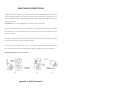
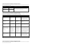
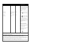
1
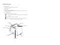
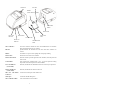
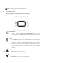
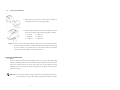
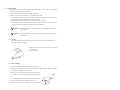
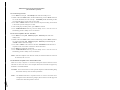
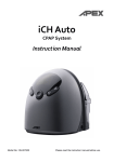
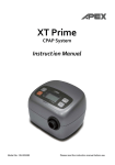
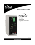
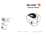
Celestia
CPAP with Heated Humidifier
Instruction Manual
Model No.: 18250
Please read the instruction manual before use.
Contents
Important Safeguards…………………..…………….….….….1
1.Introduction…………………………..........……………….3
2. Product Description……………….…...…………….…..4
3. Installation.………………………………….…...….…….6
4. Operation ……………….............................…………..9
5. Cleaning & Maintenance………………………...…………13
6. Troubleshooting ……….…..…….…………….………...15
7. Technical Specification.………..…….….………..……… 17
8. Note, Caution and Warning Statements……………….…. 18
APPENDIX A: EMC Information……………………………20
IMPORTANT SAFEGUARDS
SAVE THESE INSTRUCTIONS
READ ALL INSTRUCTIONS BEFORE USING
WARNING –
1. THIS DEVICE IS NOT INTENDED FOR LIFE SUPPORT. It may stop operating due to power
interruption but no hazards to patient.
2. This device should not be used with oxygen.
3. This device should not be used in the vicinity of a flammable anesthetic mixture in combination with
oxygen or air and nitrous oxide.
4. The airflow for breathing generated by this device may be as much as 7°C (12.6°F) higher than the room
temperature. This device SHOULD NOT be used if the room temperature is warmer than 35°C (95°F) to
prevent the airflow temperature from exceeding 40°C (104°F) and causing irritation to your airway.
5. If this device overheats, it will stop operating and show “Error Message 002” on the display. After
cooling down to proper temperature, the device can restart again.
6. This machine should be used only with masks (and connectors) recommended by the manufacturer, or by
your physician or respiratory therapist. A mask should not be used unless the CPAP machine is turned on
and operating properly. The vent holes associated with the mask should never be blocked for proper
exhaling purpose.
7. At low CPAP pressure, some exhaled gas may remain in the mask and be re-breathed.
CAUTION –
U.S. Federal law restricts this device to sale by or on the order of a licensed physician.
1
DANGER -To reduce the risk of electrocution:
1. Always unplug this product immediately after using.
2. Do not use while bathing.
3. Do not place or store product where it can fall or be pulled into a tub or sink.
4. Do not place in or drop into water or other liquid.
5. Do not reach for a product that has fallen into water. Unplug immediately.
6. Do not reach into the water or other liquids, if product falls into water or other liquids. Unplug it
immediately.
WARNING -To reduce the risk of burns, electrocution, fire or injury to persons:
1. This product should never be left unattended when plugged in.
2. Close supervision is necessary when this product is used by, on, or near children or invalids.
3. Use this product only for its intended use as described in this manual, do not use attachments not
recommended by the manufacturer.
4. Never operate this product if it has a damaged cord or plug, if it is not working properly, if it has been
dropped or damaged, or dropped into water. Return the product to a service center for examination and
repair.
5. Keep the cord away from heated surfaces.
6. Never block the air openings of this product or place it on a soft surface, such as a bed or couch, where
their openings may be blocked. Keep the air opening free of lint, hair, and other similar particles.
7. Never drop or insert any object into any opening or hose.
8. Follow the national requirement to dispose unit.
9. Recommended operating atmospheric condition is above sea level up to 8000 feet, if goes higher than
8000 feet, re-calibration is then required.
10. Do not operate the device before mask and water chamber installed.
11. Disconnect the water chamber from the device when not in use, water entering the device may result in
electric shock hazard or damage.
12. Do not use if water comes in contact with the device or enters the tubing.
13. This device is not for use with patients whose supraglottic airways have been bypassed.
14. Do not use this device on the floor.
15. Do not cover blanket or clothes on the device.
16. Do not remove water chamber while humidifier is heating. Do not touch the heater plate for 30 minutes
after the device is disconnected from the mains.
2
1. Introduction
This manual should be used for initial set up of the system and saved for reference purpose.
1.1
General Information
Obstructive Sleep Apnea (OSA) is a condition that an intermitted and repetitive obstruction of the
upper respiratory tract causes a complete (apnea) or partial (hypopnea) block of breathing airflow
during sleep. The syndrome varies depending on the degree of relaxation of the tongue and soft
palate muscle.
The most common treatment for OSA is Continuous Positive Airway Pressure (CPAP). CPAP devices
can deliver a constant air pressure into your upper airway via a nasal mask. This constant air pressure
can keep your airway open during sleep, therefore prevents the OSA.
This device is a micro-processor controlled continuous positive airway pressure device. It features
the illuminated, menu-driven LCD display, universal power supply, and ramp time adjustment. The
ramp time adjustment and ultra quiet operation ensure you to fall asleep comfortably while air
pressure slowly build up to treatment level. The user compliance meter records the total system’s
operating time for physician’s reference.
EMC Warning Statement
This equipment has been tested and found to comply with the limits for medical devices to the
IEC 60601-1-2:2004. These limits are designed to provide reasonable protection against harmful
interference in a typical medical installation. This equipment generates, uses and can radiate radio
frequency energy and, if not installed and used in accordance with the instructions, may cause
harmful interference to other devices in the vicinity. However, there is no guarantee that interference
will not occur in a particular installation. If this equipment does cause harmful interference to other
devices, which can be determined by turning the equipment off and on, the user is encouraged to try
to correct the interference by one or more of the following measures:
- Reorient or relocate the receiving device.
- Increase the separation between the equipment.
- Connect the equipment into an outlet on a circuit different from that to which the other device(s) are
connected.
- Consult the manufacturer or field service technician for help.
This system has been tested and compliance to the following volunteer standards:
FDA
1.2 Intended Use
This device is intended to provide continuous positive airway pressure (CPAP) for the treatment of
adult Obstructive Sleep Apnea (OSA). The integrated heated humidifier is designed to increase the
humidity of the air from the CPAP thereby relieving the symptoms of a dry nose and throat that some
people may experience.
NOTE: Equipment not suitable for use in the presence of a flammable anesthetic mixture with
air or with oxygen or nitrous oxide.
3
2. Product Description
Components including:
(1)
Main CPAP device with integrated heated humidifier
(2)
Detachable power cord
(3)
User manual
(4)
Flexible air tubing with 1.8 m length
(5)
Full face or nasal mask and headgear straps (Optional, Always use CE certified and 510(k)
cleared mask for CPAP)
(6)
Carrying bag (optional)
(7)
USB cable and Easy Compliance CD (Optional)
Note 1: ONLY for Physician or Technician to download data. Patient should not use this
function.
Note 2: Only applicable for devices with USB port.
CAUTION – Patient should not connect the device to the personal computer for data
downloading. This may cause the CPAP system failure
LCD Display
UP Button
MENU
DOWN Button
START/STANDB
Y
Power Switch
Air Filter
USB Connector
4
Outlet Port
Inlet Port
Baffler
(Inside Water Chamber)
Heater Plate
Switch
Heater Plate
Fill Line
Power ON
Indicator
Removable
Base
Control Knob
Power Socket
Heater ON
Indicator
Water Chamber:
Water Chamber
Slider
The water chamber contains the water for humidification. Its removable
base plate allows itself ease for cleaning.
Fill Line:
Symbol indicates the maximum level of water that water chamber can
contain.
Baffler:
The baffler can prevent water spillage due to improper shaking.
Heater Plate:
Warms the water in the water chamber.
Heater Plate Switch:
When the switch is pressed against the water chamber, the heater plate will
start to work.
Control Knob:
This control knob, graduated from 1 to 6, is used to adjust the heating
Power On Indicator
When lit, this indicates the humidifier is turned on and ready for operation.
temperature of the heater plate from 30°C to 60°C.
(Green LED):
Heater On Indicator
When lit, this indicates the heater is turned on.
(Yellow LED):
Inlet Port with Silicon
Connect to the outlet port of the CPAP device.
Connector:
Outlet port:
Connect the flexible tubing here.
Water Chamber Slider:
Lock and unlock the water chamber
5
3. Installation
3.1 Unpacking
To secure its contents inside, the device and accessories are bundled in a paper packaged box.
Unpack this box by removing the device and its accessory and checking for any damage, which may
have occurred during shipping. If there are damages, please contact your dealer immediately.
3.2 Setting Up
1) Place the device on a flat surface and at a lower
level than your sleeping position.
2) Connect the power cord to the device and plug
into main electrical outlet. Turn on the device
by pressing the ON/OFF switch on the left side
of the device
Once the device is turned on, it is in ready to
operate position (“STANDBY” sign appears in
LCD display)
NOTE: The plug is also served to
disconnect the device.
3) Connect one end of the air tubing firmly to the
air outlet on the back of the device. As shown
in the left figure.
6
4) Connect the other end of the air tubing to the
mask system. Putting on the mask and
headgear according to the mask instruction
manual.
Daily Use for the Integrated Humidifier
5)
Fill the chamber to the fill line
with distilled water (approx. 350 ml).
6) Slide the chamber into place. Make sure the
silicon connector on the inlet connector fit
securely over the CPAP device air outlet.
Note: Make sure the water chamber is pushed to
the end to press against the heater plate
switch. At the same time, the heater on
indicator will be lit to indicate the heater
plate starts to warm.
Note: The heater will be automatically turned off
while the water chamber is removed from
the heater platform.
7
3.3 WARNING & CAUTION
WARNING:
This CPAP machine should be used only with special masks (or connectors)
recommended by the manufacturer of the CPAP machine, or by your physician
or respiratory therapist. A mask should not be worn unless the CPAP machine
is turned on and operating properly. The vent hole associated with the mask
should never be blocked for proper exhaling purpose.
If the vent hole is blocked, the CPAP machine will stop and show message
“Error 002”, after cooling down, please re-connect the power cord to reset
the machine.
WARNING:
When the CPAP is not in operation, oxygen may accumulate within the CPAP
device enclosure, and it may create the risk of fire. This warning applies to
most of the CPAP models.
WARNING:
This device SHOULD NOT be used if the room temperature is warmer than
35°C (95°F) to prevent the temperature of air delivered to nasal mask over
40°C (104°F).
WARNING:
This device SHOULD NOT be used in the vicinity of a flammable anesthetic
mixture in combination with oxygen or air and nitrous oxide.
WARNING:
Recommended operating atmospheric condition is above sea level up to 8000
feet, if goes higher than 8000 feet, re-calibration is then required.
CAUTION:
At low pressures, some exhaled gas may remain in the mask and be
re-breathed.
CAUTION:
Make sure the environment around the machine is dry and clean. Dust and
foreign particles may affect the treatment. Keep the air inlet on the back of
the machine clear to prevent overheating and damage of the device. Do not
place the machine near a source of hot or cold air. Extreme cold or hot
environment may damage user's respiratory airway.
CAUTION:
Do not connect the device to the personal computer for data downloading
during the treatment. This may cause the CPAP system failure.
CAUTION:
If there is a possibility of electro-magnetic interference with mobile phones,
please increase the distance between devices or turn off the mobile phone.
8
4. Operation
NOTE: Always read the operating instruction before use.
4.1
Control Panel Description
Buttons arrangement on control panel and main use of the buttons:
START/STANDBY
To start the treatment, simply press the "START/STANDBY" button. To stop the
treatment, press the "START/STANDBY" button again. The display will switch
between [STANDBY] and Therapy Pressure [ XX.X cmH 2 O] in cmH 2 O unit.
MENU
Press the "MENU" button to enter the setting mode when device is in standby mode.
The adjustment setting includes ramp time selection, ramp starting pressure, altitude
compensation, therapy pressure adjustment, alarm ON/OFF, clock alarm setting,
compliance meter, and total operating meter. When each setting's value has been
changed, press "MENU" for confirmation and press "MENU" again for next
setting selection. Please refer to 4.2 Function Description section for detailed
information.
UP
Press
the "UP" button to select the increasing value.
DOWN
Press the "DOWN" button to select the decreasing value.
9
4.2 Function Description
(1) Ramp Time
Ramp time function allows user to fall into sleep with a lower, comfortable pressure and helps
users gradually accustomed to increasing treatment pressure. The first selection of pressing
"MENU" is [Ramp XX MIN]. When the "MENU" setting is in [Ramp XX MIN] mode, press
"UP" or "DOWN" button to set the preferred ramp time and press "MENU" for confirmation.
There are 10 adjustable levels, 0, 5, 10, 15, 20, 25, 30, 35, 40 and 45 minutes.
(2)Ramp Starting Pressure
Press "MENU" button to select [Ramp P XX.X] menu, press "UP" or "DOWN" button to set
the preferred ramp starting pressure and press "MENU" for confirmation. The ramp starting
pressure can be changed from 3 cmH 2 O to “Therapy Pressure – 1” cmH 2 O. For example, if your
therapy pressure is 10 cmH 2 O, the maximum ramp starting pressure you can select is 9 cmH 2 O.
(3) Therapy Pressure
Press "MENU" button to select [P
XX.XcmH2 O] menu, you can view the current pressure
setting displayed in cmH 2 O unit. Therapy pressure is adjustable only by the provider, a
respiratory therapist or physician.
NOTE: The therapy pressure is to only be prescribed by a physician.
(4) Altitude Compensation
Press "MENU" button to select [Alt XXX] menu, press "UP" or "DOWN" button to set the
preferred altitude compensation level from 1 to 3. The level should be set depending on your
elevation above sea level. Once the preferred level has been selected, press "MENU" for
confirmation.
1
0 ~ 2600 ft
0 ~ 800 m
2
2601 ~ 5200 ft
801 ~ 1600 m
3
5201 ft ~8000 ft
1601 m ~2400m
NOTE – Altitude compensation setting is mainly for the sensitivity adjustment for low
pressure alarm at mask off or leakage situation. This device equipped with pressure sensory
feedback mechanism by PWM control. Whenever air leakage or mask off occurs, device will
compensate more PWM value to achieve device’s targeted pressure.
10
(5) Total Meter
Press "MENU" button to select [TM XXXX.X hr] menu, the total compliance meter records the
total number of hours that the device has been active. The meter should only be re-set by the
provider, a respiratory therapist or by a physician.
(6) Compliance Meter
Press "MENU" button to select [CM XXXX.X hr] menu, the compliance meter records the total
therapy hours for the device. The compliance meter should be re-set only by the provider, a
respiratory therapist or by a physician.
(7) Alarm
Press "MENU" button to select [Alarm on/off] menu, press "UP" or "DOWN" button to set the
alarm on or off. When alarm is turned on, the audible alarm will activate with warning messages
showed on the LCD display. Set alarm off for mute the audible alarm.
(8) Clock Alarm
Press "MENU" button to select [Clock Alarm on/off] menu, press "UP" or "DOWN" button to
set the clock alarm on or off. When clock alarm is set on, the display will show the time on the
left side. Press "UP" or "DOWN" button to set the time to wake you up. Once the clock alarm is
activated, press the start/standby button to mute the audible alarm.
(9) Clock
Press "MENU" button to select [Clock XX:XX] menu, press "UP" or "DOWN" button to set the
current time.
(10) Turn off the Device
Turn off the device by pressing the ON/OFF switch on the left side of the device
NOTE:
Once the setting is confirmed, press “MENU” button. Otherwise, the device will
automatically go back to standby without saving the modification if no action
is taken in 5 seconds.
(11) Event Indication
While the device is on standby mode, press UP" and "DOWN" button at the same time to see the
latest one data of Apnea Index (AI), Hypopnea Index (HI) and Snoring Index (SI) on the display.
Press "MENU" button to show each index in sequence. To go back to standby mode, press
"START/STANDBY" button.
NOTE: Once the device is re-started, all the indexes will be re-calculated. The whole
data of these indexes are only seen by respiratory therapists or physicians by
using Easy Compliance 2.1 playback software.
11
4.3
Flowchart of Menu settings
Enter the user's menu mode by pressing the “MENU” button.
Down
Menu
Up
Ramp
(Ramp Time)
< 0, 5, 10, 15, ……………., 45> min
Ramp P
(Ramp Starting Pressure)
< 3, 3.5, 4, 4.5, ……………., 17> cmH2O
P
(Therapy Pressure)
< 4, 4.5, 5, 5.5, ……………., 18> cmH2O
Alt.
(Altitude Compensation)
< 1, 2, 3 >
TM
(Total Meter)
< XXXX.X > hr
CM
(Compliance Meter)
< XXXX.X > hr
Alarm
< on/off >
Clock Alarm
< on/off >
Clock
< hh:mm >
Confirm
Menu
In each setting, when the preferred value has been selected, press "MENU" for confirmation
and press "MENU" again to enter next selection.
NOTE: For physicians, please refer to a separated “Physician’s Additional Instruction” page.
12
4.4
Using the heated humidifier
1.
While the device is turned on., the heater power on indicator on
the right side of the device will be lit (green light)
2. Adjust the heater temperature to the desired setting by the control
knob. The 1-6 setting corresponds to the temperature as follows:
1 = about 30°C
2 = about 39°C
3 = about 43°C
5 = about 51°C
4 = about 47°C
6 = about 60°C
Danger: In order to avoid the destruction or damages of the device or even the hazard of electric
shock, when the water chamber is attached, DO NOT fill water from the outlet port of
the water chamber. Users must fill water no more than the marking for maximum
volume after the water chamber is removed from the device.
5. Cleaning & Maintenance
5.1
Device
The device should be checked and dusted regularly (at least every 30 days). Wipe with a damp
cloth and a mild detergent and keep it free from dust. If other detergent is used, choose one that
will have no chemical effects on the surface of the plastic case. All parts should be air-dried
thoroughly before use. Inspect the device and all circuit parts for any damage after cleaning and
replace it if necessary.
WARNING: Don’t try to open this device. Repairs and internal servicing should only performed
by an authorized service agent. Don’t drop any subject into the air tube or air outlet.
13
5.2 Tubing and Mask
The tubing and mask should be checked and cleaned daily. Please refer to the cleaning
instruction packaged with the accessories.
1. Disconnect the air tubing from the air outlet of the device.
2. Remove the air tubing and headgear straps from the nasal mask.
3. Use a mild detergent and prepare the detergent according to manufacturer's recommendations.
Tubing and mask can be washed and rinsed in warm water.
4. Rinse thoroughly and make sure they are completely dry before next use.
5. All items of the mask and air tubing are subject to normal wear and tear and may eventually be
replaced. Replace the mask and the air tubing if they are damaged.
WARNING: Do not use any cleaner containing fragrance or conditioners as they will
leave a residue.
WARNING: The mask must not be re-used by another person. This is to avoid the risk of
cross-infection.
5.3
Air Filter
The air filter should be checked and replaced every 30 days, or more often if this device is
operated in a dusty environment.
1. Remove the dirty filter from the enclosure on the front
of the device.
2. Insert a new filter.
5.4
Water Chamber
1. Turn the device off and allow the heater and water to cool.
2. Disconnect the flexible tubing from the water chamber. Slide the water chamber out of the
heater platform. Empty the remaining water.
3. Push the water chamber slider to the left and gently remove
the chamber base by pressing downward on the metal base
tab.
4. Use a mild detergent to wash all the chamber parts. Rinse all
the parts with clear water and allow them to air dry.
5. All items of the chamber are subject to normal wear and tear
14
and may eventually be replaced. Replace the chamber parts if any damage is present.
6. Troubleshooting
The table below lists troubleshooting solutions for the problems that may happen. If the problem persists,
contact your equipment provider service agent.
P roble m
No display
P o s s ib l e C a u s e s
1.
S o lu t i o ns
The power cord is not
1.
Ensure the power cord is connected.
connected to the power
2.
Contact your equipment provider for
socket.
2.
repair.
LCD failure or controlled
PCB failure.
Display code incorrect
LCD failure or controlled PCB
Contact your equipment provider for repair.
failure.
Illuminant under LCD is
LED failure
Contact your equipment provider for repair.
Buttons disable
Button failure
Contact your equipment provider for repair.
Air delivered is slow
1.
During ramp time.
1.
Check the ramp time setting
2.
Filter is too dirty.
2.
Change or clean the filter regularly.
3.
Flow generator failure.
3.
Contact your equipment provider for
not on
Integrated humidifier
power on indicator not
light
Heater on indicator not
light at all
There is no air flow on
through the mask
Condensation in mask or
flexible tube
repair.
1. Plug in the power cord to a working AC
outlet.
2. See Setup procedure and turn the power
on.
3. Contact your local agent or EU
representative for service.
4. Contact your local agent or EU
representative for service.
1. Heater plate over heating
1. Contact your local agent or EU
2. PCB indicator worn out
representative for service.
2. Contact your local agent or EU
representative for service.
1. Device is not turned on or
1. Check the power cord is connected
working correctly
properly.
2. Flexible tubing is not connected 2. Reconnect the flexible tubing correctly.
right.
3. Unblock the flexible tube.
3. Flexible tube is blocking.
1. The heater plate setting is too 1.Adjust the control knob to low temperature
high.
setting.
2. The operating environment or 1. Remove any air conditioner which may
position of heated humidifier is
nearby the heated humidifier. Or keep
room temperature up near 25 not properly. The temperature
1. Power cord not plug into a
working AC outlet.
2. Power switch is not turned on
3. PCB or indicator worn out
4. Fuse blown out
15
Water Leakage
close to mask or flexible tube is
low.
1. Assembly of water chamber is 1. Remove the water chamber from the
heated humidifier, pull out the water and
not proper or incorrectly.
reassemble the water chamber again,
2. Water chamber or removable
make sure the removable base plate is
base plate worn out.
right fit into water chamber, and fill the
water till it reach fill line and check if it
still leak or not.
2. Replace a new water chamber.
Error / Warning Messages show in LCD.
Message type
Definition
Error:
Error for abnormal system settings
Message in LCD
Error
001
Error
002
Primary function can’t
execute.
Error for flow generator failure
Warning:
Out of system memory
Warn
001
System memory is nearly full
Warn
002
NOTE: When the warning message appears, contact your physician or equipment provider to download the
memory data and reset the meter.
7. Technical Specifications
Ite m
Power Supply
Sp e c i f i c a t i o n s
16
100-120VAC, 50/60Hz, 0.5A (For 120V system)
220V-240VAC, 50/60Hz, 0.3 A (For 230V system)
Therapy Pressure
4 –18 cmH 2 O (adjustable in 0.5 cmH 2 O increment)
Ramp Time
0 – 45 minutes (adjustable in 5-minute increment)
Ramp Starting Pressure
3 – 17 cmH 2 O (adjustable in 0.5 cmH 2 O increment)
Dimensions (W x D x H)
16.5 X 24.5 X13.7 cm
Weight
1.4 kg (3.1 lbs)
Sound Level
30 dBA at 10 cmH 2 O, 1 meter distance
Water Capacity:
350ml
Heater Settings:
1 to 6 from 30°C-60°C
Pressure Drop:
0.2cmH 2 O @ 60LPM
Humidity Output:
10-40mgH 2 O/L
Operating: +5°C to +35(C (+41°F to +95°F)
Temperature
Storage: -15 to 50 (+5°F to +122°F)
Environment
Shipping: -15 to 70 (+5°F to +158°F)
Humidity
Operating: 15%RH to 95%RH non-condensing
Storage: 10%RH to 90%RH non-condensing
Shipping: 10%RH to 90%RH non-condensing
Air Tubing
Flexible plastic, 1.8m (approx.)
EN 60601-1
Class I, Type BF, IPX0
EN 60601-1-2
Applied Parts Nasal Mask
Classification:
Not suitable for use in the presence of a flammable anesthetic
mixture (No AP/APG Protection)
Continuous operation.
Note: the manufacturer reserves the right to modify the specification without notice.
17
BF symbol, which indicated this product is according to the degree of protecting against
electric shock for type BF equipment.
Attention, should read the instructions.
Grounding terminal
Disposal of Electrical & Electronic Equipment (WEEE):
This product should be handed over to an applicable collection point for the recycling of
electrical and electronic equipment. For more detailed information about the recycling of
this product, please contact your local city office, household waste disposal service or the
retail store where you purchased this product.
Fill line
Air flow direction
8. NOTE, CAUTION, AND WARNING STATEMENTS
NOTE:
CAUTION:
Indicate information that you should pay special attention to.
Indicate correct operating or maintenance procedures in order to prevent damage to or
destruction of the equipment or other property.
WARNING:
Calls attention to a potential danger that requires correct procedures or practices in order to
prevent personal injury.
18
GROUNDING INSTRUCTIONS
This product should be grounded. In the event of an electrical short circuit grounding reduces the risk of
electric shock by providing an escape wire for the electric current. This product is equipped with a cord
having a grounding wire with a grounding plug. The plug must be plugged into an outlet that is properly
installed and grounded.
DANGER-improper use of the grounding plug can result in a risk of electric shock.
If repair or replacement of the cord or plug is necessary, do not connect the grounding wire to either flat
blade terminal. The wire with insulation having an outer surface that is green with or without yellow stripes
is the grounding wire.
Check with a qualified electrician or serviceman if the grounding instructions are not completely understood,
or if in doubt as to whether the product is properly grounded.
If is necessary to use an extension cord, use only a 3-wire extension cord that has a three-balde grounding
plug, and a 3-slot receptacle that will accept the plug on the product. Replace or repair a damaged cord.
GROUNDING METH (For 120V System Only)
Appendix A: EMC Information
19
Guidance and Manufacturer’s Declaration- Electromagnetic Emissions:
This device is intended for use in the electromagnetic environment specified below. The user of this device should make
sure it is used in such an environment.
Emissions Test
Compliance
Electromagnetic Environment-Guidance
Harmonic emissions
IEC61000-3-2
Class A
Voltage fluctuctions /
Flicker emissions
IEC61000-3-3
Complies
The device is suitable for use in all establishments, including
domestic establishments and those directly connected to the
public low-voltage power supply network.
Guidance and Manufacturer’s Declaration- Electromagnetic Immunity:
This device is intended for use in the electromagnetic environment specified below. The user
of this device should make sure it is used in such an environment.
Immunity Test
IEC60601 test level
Compliance
Electromagnetic
Environment-Guidance
Electrostatic Discharge(ESD)
IEC61000-4-2
±6kV contact
±8kV air
±6kV contact
±8kV air
Floors should be wood, concrete or
ceramic tile. If floors are covered with
synthetic material, the relative
humidity should be at least 30 %.
Electrical fast transient/ burst
IEC61000-4-4
±2kV for power
supply line
±1kV for input/out
line
±1kV for differential
mode
±2kV for common
mode
±2kV for power
supply line
±1kV for input/out
line
±1kV for differential
mode
±2kV for common
mode
Mains power quality should be that
of atypical commercial or hospital
environment
Voltage dips, short
interruptions and voltage
variations on power supply
input lines
IEC61000-4-11
<5 % UT(>95 % dip in
UT)for 0,5 cycle
40 % UT(60 % dip in
UT)for 5 cycles
70 % UT(30 % dip in
UT)for 25 cycles
<5 % UT(>95 % dip in
UT)for 5 sec
<5 % UT(>95 % dip in
UT) for 0,5 cycle
40 % UT(60 % dip in
UT) for 5 cycles
70 % UT(30 % dip in
UT) for 25 cycles
<5 % UT(>95 % dip in
UT) for 5 sec
Mains power quality should be that
of atypical commercial or hospital
environment. If the user of this
device requires continued operation
during power mains interruptions, it
is recommended that the device be
powered from an uninterruptible
power supply or a battery.
Power frequency
(50/60Hz) magnetic field
IEC61000-4-8
3 A/m
3 A/m
Power frequency magnetic fields
should be at levels characteristic of
atypical location in a typical
commercial or hospital environment.
Surge
IEC61000-4-5
Mains power quality should be that
of atypical commercial or hospital
environment.
NOTE: UT is the a.c. mains voltage prior to the application of the test level
Guidance and Manufacturer’s Declaration- Electromagnetic Immunity:
20
This device is intended for use in the electromagnetic environment specified below. The user of this device should make
sure it is used in such an environment.
Immunity Test
IEC60601 test level
Compliance
Electromagnetic
Environment-Guidance
Portable and mobile RF
communications equipment should
be used no closer to any part of this
device, including cables, than there
commended separation distance
calculated from the equation
applicable to the frequency of the
transmitter.
Conducted RF
IEC 61000-4-6
3Vrms150 kHz to 80
MHz outside ISM
bandsa
3Vrms
Radiated RF
IEC 61000-4-3
3 V/m 80 MHz to
2.5 GHz
3V/m
Recommended separation distance
d = 1.2 P 150kHz to 80MHz
d = 1.2 P 150kHz to 80MHz
d = 2.3 P 80 MHz to 2.5G MHz
Where P is the maximum output
power rating of the transmitter in
watts (W) according to the transmitter
manufacturer and d is the
recommended separation distance in
meters (m).b
Field strengths from fixed RF
transmitters, as determined by an
electromagnetic site survey c, should
be less than the compliance level in
each frequency range d .
Interference may occur in the vicinity
of equipment marked with the
following symbol:
NOTE 1 At 80 MHz and 800 MHz, the higher frequency range applies.
NOTE 2 These guidelines may not apply in all situations. Electromagnetic propagation is affected by absorption and
reflection from structures, objects and people.
a The ISM (industrial, scientific and medical) bands between 150 kHz and 80 MHz are 6,765 MHz to 6,795
MHz;13,553 MHz to 13,567 MHz; 26,957 MHz to 27,283 MHz; and 40,66 MHz to 40,70 MHz.
b The compliance levels in the ISM frequency bands between 150 kHz and 80 MHz and in the frequency range 80
MHz to 2,5 GHz are intended to decrease the likelihood that mobile/portable communications equipment could cause
interference if it is inadvertently brought into patient areas. For this reason, an additional factor of 10/3 is used in
calculating the recommended separation distance for transmitters in these frequency ranges.
21 for radio (cellular/cordless) telephones and land mobile
c Field strengths from fixed transmitters, such as base stations
radios, amateur radio, AM and FM radio broadcast and TV broadcast cannot be predicted theoretically with accuracy. To
assess the electromagnetic environment due to fixed RF transmitters, an electromagnetic site survey should be
considered. If the measured field strength in the location in which the device is used exceeds the applicable RF
compliance level above, the device should be observed to verify normal operation. If abnormal performance is
observed, additional measures may be necessary, such as reorienting or relocating the device.
d Over the frequency range 150 kHz to 80 MHz, field strengths should be less than 3 V/m.
Recommended separation distances between
portable and mobile RF communications equipment and this device
This device is intended for use in an electromagnetic environment in which radiated RF disturbances
are controlled. The customer or the user of this device can help prevent electromagnetic interference
by maintaining a minimum distance between portable and mobile RF communications equipment (transmitters) and this
device as recommended below, according to the maximum output power of the communications equipment
Rated maximum output Separation distance according to frequency of transmitter m
power
of transmitter
80 MHz to 800 MHz
800 MHz to 2,5 GHz
150 kHz to 80 MHz
W
d = 1.2 P
d = 1.2 P
d = 2.3 P
0.01
0.12
0.12
0.23
0.1
0.38
0.38
0.73
1
1.2
1.2
2.3
10
3.8
3.8
7.3
100
12
12
23
For transmitters rated at a maximum output power not listed above, the recommended separation distance d in
meters (m) can be estimated using the equation applicable to the frequency of the transmitter, where P is the
maximum output power rating of the transmitter in watts (W) according to the transmitter manufacturer.
Note 1: At 80 MHz and 800 MHz, the separation distance for the higher frequency range applies.
Note 2: These guidelines may not apply in all situations. Electromagnetic propagation is affected by absorption
and reflection from structures, objects, and people.
22
Additional instruction for Physician and Technician
(Do not distribute to patients)
1. To Set the Therapy Pressure
1. Press "MENU" to select [P
XX.XcmH 2 O] menu while in the standby screen.
2. Hold the "UP" and "DOWN" button, and then simultaneously press the "MENU" button for
one second. Meanwhile, the LCD screen [P
XX.XcmH 2 O] should start blinking to allow
you to adjust the therapy pressure from 4 to 18 cm H 2 O.
3. Press "UP" or "DOWN" button to increase or decrease the pressure setting. The increment
or decrement of pressure setting is 0.5 cm H 2 O.
4. After selecting the prescribed pressure, press "MENU" to confirm.
5. Press “START/STANDBY” button to go back to standby screen or leave the device to
automatically go back to standby screen 5 seconds later.
2. To Re-set the Compliance Meter & Total Meter
1. Press "MENU" to select [TM XXXX.X hr] or [CM XXXX.X hr] menu while in the
standby screen.
2. Hold the "UP" and "DOWN" button, and then simultaneously press the "MENU" button for
one second. Meanwhile, [TM XXXX.X hr] or [CM XXXX.X hr] will start blinking and
“CLEAR ” will show on the LCD display.
3. Press “UP” or “DOWN”. The LCD screen will show “CLEAR OK” and the total meter or
compliance meter record will be erased so the value becomes 0.0 hr.
4. Press "MENU" to confirm the reset function.
5. Press “START/STANDBY” button to go back to standby screen or leave the device to
automatically go back to standby screen 5 seconds later.
NOTE – When the compliance meter has been cleared, the total meter will also be cleared at
the same time, and vice versa.
3. To Download the Compliance Meter and Total Meter Data
Please refer to Easy Compliance 2.1 CPAP Data Management Software instruction. Use the
USB cable to connect the device with a computer which has been tested and approved by
IEC60601-1 or IEC60950 standard.
CAUTION – Do not connect the device to the personal computer for data downloading during
the treatment. This may cause the CPAP system failure.
NOTE – This additional instruction is separated because of concerns with rental service
management and accidental wrong setting by others. Please tear off this page from
manual before deliver this product to end-user.
Drive Medical Design & Manufacturing
99 Seaview Boulevard
Port Washington, NY 11050
516-998-4600
www.drivemedical.com