1
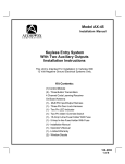
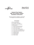
1
Channel
B W- 1 0 6 0
S E L F - C O N TA I N E D
SECURITY SYSTEM
INSTALLATION MANUAL
Before Installing:
Timing Information:
1. Read the INSTRUCTIONS!
2. USE A DIGITAL OR ANALOG
VOLT/OHM METER
3. BEFORE MOUNTING THE PRODUCT
CHECK THE POSSIBLE LOCATIONS
FOR THE SIREN AND LED BEFORE
YOU PERMANENTLY INSTALL THEM.
4. PROTECT THE VEHICLE BY USING
FENDER COVERS.
Automatic reset time: 45 seconds,
Panic output reset time: 45 seconds,
Arming time: (when all inputs are monitored): 3 seconds-active arm.
Armed output: The Gray wire will produce a grounded output when system is
armed.
Flashing Parking Light Output:
Armed: 1 second pulsed, Disarmed: 2-one
second pulses. System triggered: 1 second
pulse on, 1 second off, repeated for 45
seconds.
5. ROLL DOWN THE DRIVER’S WINDOW BEFORE STARTING THE INSTALLATION.
6. ALWAYS LOOK BEFORE DRILLING.
MAKE SURE YOU WILL NOT CAUSE
DAMAGE TO VEHICLE HOSES, ELECTRICAL LOOMS OR PHYSICAL DAMAGE
TO VEHICLE.
Input Zone Out Feature:
If a door input remains on for 4 consecutive cycles (45 seconds) that input will be
ignored. If the input returns to a non-triggered state for 30 seconds it will be monitored by the system again.
1
PROGRAMMABLE FEATURES
To program these specific features
follow the procedure:
5. Code Learning Mode: If you wish to
“teach” the system different remote
controls:
1. Anti Car Jacking: Turn the ignition
key to the ON position.Within 5 seconds
press and hold button #2 for 5 seconds.
When Anti Car Jacking is enabled, the
siren will chirp once.When disabled it will
chirp twice.
a. Make sure system is disarmed or in
valet mode,
b. Turn the ignition switch on 5 times
within 5 seconds and leave it in the on
position (ON, OFF, ON, OFF, ON, OFF,
ON, OFF, then ON), you will hear one
chirp from the siren, the LED will flash
one time,You must press all of the arming
buttons on all transmitters that you
desire to operate.You will hear a chirp
after the system has learned each remote
control.The system will hold 3 different
codes in memory.
2. Current Sensor: Turn the ignition key
to the ON position, within 5 seconds
press and hold button #1 for 5 seconds,
when current sense is enabled siren will
chirp once, when disabled it will chirp
twice.
3. Shock Sensor: Turn the ignition key
to the ON position, within 5 seconds
press and hold buttons #1 & #2 for 5
seconds, the siren will chirp 5 times after
3 seconds.The system is now ready to
learn the impact. Hit the car with the
same level you want to trigger the alarm.
After learning the impact level, the siren
will sound a burst of chirps confirming it
has learned the impact level.
c. Siren will chirp after 5 seconds to exit
learn mode. If the green wire is not connected to the ignition switch, touch wire
to 12V+ five times within 5 seconds.
NOTE: Once you enter the code learning mode, the system will throw out any
previously programmed remotes. If you
are programming two remotes with the
same code, the system will acknowledge
only the first remote. Even though both
remotes will operate the system.
4. Temporary Remote Trigger Bypass:
If you wish to have the system ignore the
door inputs, but wish to have the starter
disable feature engaged:
6. Silent Arm/Disarm: If you wish to
arm or disarm your alarm, but do not
want the siren to chirp:
a. Press Button #1, you will hear a normal arming chirp, (as long as arming
chirps are on).
a. Press Button #2 momentarily.This will
temporarily delete the arm or disarm
chirps. Chirp can only be heard if standing
right next to the vehicle. Chirps will be
muted for one complete cycle (arm/disarm).
b. Within 5 seconds press Button #2, you
will hear a second short chirp, confirming
that all inputs will not be monitored.
Once you disarm and rearm, the doors
will be monitored normally.
2
INSTALLATION
INSTRUCTIONS:
3. Connect Starter
Disable Relay: (Optional)
Using a volt/ohm meter locate the starter
wire (normally a heavier gauge wire) off
of the ignition switch.The meter will read
12V+ only during cranking.When the
starter wire has been located, cut the
wire, the vehicle should not be able to
start now. Connect the gray wire to a
relay (See starter disable relay on page 5).
1. Mount the Siren:
Locate a suitable place under the hood,
away from hot and moving engine parts
such as manifolds, turbo chargers, fan
belts, etc. Secure siren by screwing bracket to a solid location under the hood.
Make sure that there is no outside access
to both siren and wire from underneath
the vehicle or through the grill.
Point the siren down so that water may
not accumulate inside the siren bell.
Ground the black wire of the siren to a
solid ground; preferably, use a star washer
and ring terminal.
When running wires inside the vehicle,
use either tape or split loom tubing.
Always use either existing grommets or if
a new hole is needed protect the wire
from chaffing by installing a proper size
grommet.
4. Connect Negative door
input: Blue wire on main harness (Optional)
Connect the blue wire from the harness
to the wire that shows ground when all
of the doors are opened.Verify with a
volt/ohm meter. Make sure that all doors
when opened separately make the target
wire provide a ground output.
5. Connect Hood/ Trunk switch
input:Blue wire on main harness (Optional)
Connect the blue wire to either or both
hood and trunk switches.They must provide a ground output when the trunk or
hood are opened.You must use a diode
to isolate your hood wire from your
door wire.
2. Install the Status
Indicator (LED): (Optional)
Locate a suitable place for the status indicator (LED), drill the appropriate size
hole (7/16”). Make sure there is enough
depth for the LED to fit all the way in,
and can be easily seen from outside the
vehicle. Carefully run the LED and 2 pin
red connector and wire harness to the
module and plug into the matching red
two pin connector on the module. Push
the LED into the hole, it should fit snugly.
6. Connect the Flashing
Parking Light Output: Yellow
wire main harness.
Using a volt/ohm meter, locate the wire
(usually on the head light switch) that
3
key is turned off, it will keep the alarm
from arming via the remote.
shows 12V+ when only the parking lights
are switched on. European vehicles may
require an additional relay if they have
separate wires that switch on the left and
right side parking lights.
This relayed output has a maximum of 10
amps. Do not hook to head lights. (See
diagram section).
9. Connect Ground Input:
Black wire on main harness
Locate a good solid chassis ground and
connect to the black wire on main harness.Verify the ground with your
volt/ohm meter.
7. Connect 12V+ Power Input:
Red wire on main harness
Connect the red fused wire on the main
harness to a constant 12V+ source.
This source wire should be at least 20
amp supply.There usually is a main constant power wire on the ignition switch.
Use volt/ohm meter to verify.
10. Plug in the main harness to
the module.
11. Test features, functions
and adjust shock sensor.
Arm and disarm system, check that the
siren chirps and parking lights are functioning normally. Make sure that the programmed features are performing correctly.
Test the door inputs (make sure that you
check that all doors trigger the system
not just the drivers door). Arm the system and try starting the vehicle, it should
not start.
Check for range with the remotes. See
that they arm and disarm all the way
around the vehicle; adjust the module
antenna location if necessary.
Using the remote check for the user features: chirp mute, temporary trigger and
bypass.
Deliver the vehicle to customer.
8. Connect the 12V+ ignition
input: Green wire on main
harness (Optional)
Connect the green wire on the main harness to a main ignition wire.This can be
also found in the main ignition switch
wire harness.Your volt/ohm meter will
read 12V+ when key is turned on.
Make sure that this ignition wire has
12V+ on even during the starting process
of the vehicle. It is important that the
voltage does not drop when the car is
starting.
Some vehicles have ignition wires that
remain or slowly drop to 0 volts.Verify
that when the ignition is shut off that the
voltage drops to 0 Volts immediately. If
the green wire has voltage on it after the
4
STATUS INDICATOR (LED) FUNCTIONS
Off= System off in Active Mode
Slow Flash= System Armed
Rapid Flash= System was triggered
On Solid= 3 second final prearm state
On Solid= (when disarmed)
-Input is open.
SILENT TEST MODE
When the system is disarmed the LED will go solid every time an input is triggered.
You can check the shock sensor, doors, hood, trunk, and the auxiliary
sensor input as well.
SIREN CHIRP STATUS
1 chirp= system armed
2 chirps= system disarmed
3 chirps= System disarmed, but alarm was triggered while away.
4 chirps= Alarm armed but there is a trigger that remains open (This occurs 25 seconds after system was armed).
FOR NEGATIVE
PARKING LIGHTS
(MOST
JAPANESE
VEHICLES)
87
87a
86
85
30
TO VEHICLE
PARKING
LIGHT
CIRCUIT
OPTIONAL STARTER DISABLER CIRCUIT
87
86
GRAY
FUEL
PUMP
IGNITION
SWITCH
YELLOW
5
x
87a
30
CUT
85
x
GREEN
WIRE
(IGNITION
12V+)
FUSE
STARTER
BLOCK
A)
B)
C)
D)
CHIRP STATUS
LED STATUS
1 Chirp = System Armed
A) Fast Flashing = System has been triggered
2 Chirps = System Disarmed
B) Steady Flashing = System Armed
3 Chirps = System has been triggered
4 Chirps= Alarm armed but there is a trigger that remains open
L.E.D.
12V
FLASHING
LIGHTS
RED
BLACK
ANTENNA
SIREN/
MODULE
HARNESS
RED/BLACK
YELLOW
NEG. TRIGGER
INPUTS FOR GLASS
SENSOR, MASS
SENSORS, NEG.
DOOR PINSWITCHES
BLUE
GRAY
BLACK
RED
5 A FUSE
GREEN
_
+
BATTERY
IGNITION
+12V
NEG. GROUND
OUTPUT FOR
STARTER INTERRUPT
POWER DOOR LOCKS
SUMMARY OF INPUTS AND OUTPUTS:
Inputs:
Outputs
1 Negative door trigger
Flashing lights: relayed - 10 amp Max
Starter Interrupt: 500 mA - negative
1 CHANNEL PROGRAMMABLE FEATURES:
Feature #1= Anti Car Jacking:
ON= Anti Car Jack
Feature #2= Shock Sensor:
ON= Shock Sensor
Feature #3= Current Sense:
ON= Current Sense
6
OFF= Anti Car Jack
OFF= Shock Sensor
OFF= Current Sense
TERMINAL NUMBERING AND WIRE COLOR CODES
#
COLOR
FUNCTION
FUNCTION
1)
Red
+12V In
Main Power. Connect this wire to the
battery POSITIVE (+) terminal with the
supplied 5 amp fuse installed at the
BATTERY end of the wire! Be sure
to read the CAUTION in item 4 of the
installation instructions.
2)
Black
Ground
Connect this wire to a clean, solid
GROUND.
3)
Blue
(-) Trigger
Connect this wire to shock, glass, radar,
other sensors, or to hood, trunk, or
door pinswitches that are GROUNDED when the door is opened.
4)
Gray
Starter
Interrupt
This output is Ground (-) whenever
the alarm is ARMED. It is used to drive
the starter interrupt relay.
5)
Yellow
Flashing
Lights(+)
Connect to 12 Volt flashing lights.
6)
Red/Black
LED(+)
7)
Green
Ignition
Input (+)
Connect ignition wire to Green
wire from the harness.
Antenna
Wire on the Receiver Module.
Do not attempt to ground the
antenna wire!
Connect to the Red wire of the BWS180 LED. Connect black wire from LED
to ground.
Not part of harness:
8)
Black
7
TROUBLESHOOTING
SYMPTOM
Range is poor
PROBABLE CAUSE
Antenna wire is grounded, module is picking up interference
from vehicles electrical system
SUGGESTED CORRECTION
Make sure antenna is not connected to anything, relocate module away from vehicle computer
modules
Vehicle starts when
armed
Wrong starter wire was cut
Locate proper starter wire
and reconnect
Car will not start when
system is disarmed
Bad connection on gray wire in
harness
Repair connection at starter
wire, replace module
Alarm system intermittently works
Bad power and ground
connections
Replace and secure power and
ground connectors
Car won’t start; Alarm
won’t function properly
Vehicle battery dead or drops
below 7.5 volts when trying to
start the vehicle
Replace battery or charge
Alarm doesn’t Arm or
Disarm
Ignition input has voltage on it,
make sure the power wire
shows 12V+
Turn key off - wrong wire connected to green wire main
harness
Alarm will not go into
Code Learning Mode
Not leaving ignition in the on
position after turning it on &
off five times. Not turning ignition on/off rapidly enough
(5 sec.)
Repeat procedure quicker
Alarm will not go into
Code Learning Mode
Green wire not connected
Connect green wire to an ignition
source
Alarm chirps 4 times 30
seconds after system is
Armed
Factory Dome light Delay is
longer than 30 seconds. Door
open or defective pin switch
If dome light delay is longer than
30 seconds no correction necessary. Replace defective pin switch
Parking lights do not
flash
Wrong wire connected to the
Yellow wire, or requires a negative output
Correct the wire connected to
the Yellow wire, using a SPDT
relay reverse polarity on Yellow
wire (see diagram)
DLC/U.S.A.
12753 Moore Street
Cerritos, California 90703
© 2000, DAVID LEVY COMPANY, INC.
(1060) February 2000, Rev. 1
8