1
REPLACEMENT OF PARTS
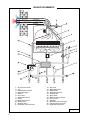
To gain access to the boiler components, proceed as follows:
• Isolate boiler from electrical supply.
• Remove outer case, if necessary sealed chamber cover, combustion chamber cover and side covers, see
“Routine cleaning and inspection”.
• Gently squeeze metal clip securing the control panel box, lift it up and hinge down.
To replace fan
• Disconnect power supply and earth leads to fan.
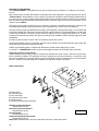
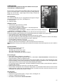
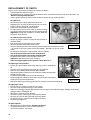
• Supporting fan, unscrew and remove two screws securing fan to front of flue hood, see diagram 18.
• Gently ease fan forwards and out of boiler.
• Fit replacement fan in reverse order to removal making
sure that mounting plate engages correctly onto flue hood
Important: Ensure that fan outlet is correctly fitted into
flue elbow at top of boiler.
To replace air pressure switch
• Locate air pressure switch in upper left hand corner of
sealed chamber.
• Pull off clear plastic tube from base of switch.
• Remove electrical connections from switch.
• Unscrew and remove two screws securing switch to upper panel and remove switch
– (or unclip air pressure switch from plastic holder – depends on type of switch
used).
• Fit electrical connections to replacement switch as follows:
One to the microswitch connection marked ‘NO 2’
One to the microswitch connection marked ‘COM 3’
• Fit replacement switch in reverse order to removal.
Important: Refit clear plastic tube as follows:
Tube from tapping point of flue hood to switch point ‘P 2 -’
To replace gas valve module
• Locate gas valve module attached to side of gas valve, see diagram
19.
• Unscrew screw (a) securing cover onto gas valve module.
• Remove cover and disconnect multi-plug from module.
• Disconnect ignition and flame sense leads from module and withdraw
module from gas valve.
• Fit replacement module in reverse order to removal.
• Reconnect ignition and flame sense leads, the connections are uniquely
sized to ensure correct replacement.
• Refit cover ensuring all sealing grommets are correctly located in module body.
Diagram 18
Diagram 19
To replace gas valve
• Ensure that gas supply is turned off at gas cock.
• Unscrew screw (a) and remove gas valve module.
• Undo nuts securing gas supply pipe between burner and gas valve and remove pipe, taking care not to lose
sealing washers, see diagram 19.
• Remove gas inlet connection to boiler.
• Unscrew 2 screws securing gas valve to boiler bottom.
• Remove gas valve by lifting upwards and out of boiler.
• Fit replacement gas valve in reverse order to removal.
• Check for gas-tightness.
To replace burner
• Remove burner as described in ‘Cleaning the burner’.
• Fit replacement burner in reverse order to removal.
• Check if the injectors are correct.
20