1
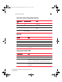
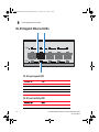
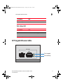
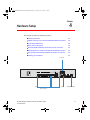
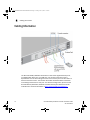
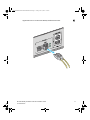
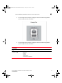
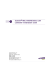
MobilityRFS4000ControllerInstallGuide.book Page i Friday, June 10, 2011 1:32 PM
®
Brocade Mobility RFS4000
Controller
Installation Guide
Supporting software release 4.3.0.0 and later
53-1001933-02 Rev B
MobilityRFS4000ControllerInstallGuide.book Page ii Friday, June 10, 2011 1:32 PM
Copyright © 2011 Brocade Communications Systems, Inc. All Rights Reserved.
Brocade, the B-wing symbol, BigIron, DCX, Fabric OS, FastIron, IronPoint, IronShield, IronView, IronWare, JetCore,
NetIron, SecureIron, ServerIron, StorageX, and TurboIron are registered trademarks, and DCFM, Extraordinary
Networks, and SAN Health are trademarks of Brocade Communications Systems, Inc., in the United States and/or in
other countries. All other brands, products, or service names are or may be trademarks or service marks of, and are
used to identify, products or services of their respective owners.
Notice: This document is for informational purposes only and does not set forth any warranty, expressed or implied,
concerning any equipment, equipment feature, or service offered or to be offered by Brocade. Brocade reserves the
right to make changes to this document at any time, without notice, and assumes no responsibility for its use. This
informational document describes features that may not be currently available. Contact a Brocade sales office for
information on feature and product availability. Export of technical data contained in this document may require an
export license from the United States government.
The authors and Brocade Communications Systems, Inc. shall have no liability or responsibility to any person or entity
with respect to any loss, cost, liability, or damages arising from the information contained in this book or the computer
programs that accompany it.
Brocade Communications Systems, Incorporated
Corporate and Latin American Headquarters
Brocade Communications Systems, Inc.
130 Holger Way
San Jose, CA 95134
Tel: 1-408-333-8000
Fax: 1-408-333-8101
E-mail: [email protected]
Asia-Pacific Headquarters
Brocade Communications Systems China HK, Ltd.
No. 1 Guanghua Road
Chao Yang District
Units 2718 and 2818
Beijing 100020, China
Tel: +8610 6588 8888
Fax: +8610 6588 9999
E-mail: [email protected]
European Headquarters
Brocade Communications Switzerland Sàrl
Centre Swissair
Tour B - 4ème étage
29, Route de l'Aéroport
Case Postale 105
CH-1215 Genève 15
Switzerland
Tel: +41 22 799 5640
Fax: +41 22 799 5641
E-mail: [email protected]
Asia-Pacific Headquarters
Brocade Communications Systems Co., Ltd. (Shenzhen
WFOE)
Citic Plaza
No. 233 Tian He Road North
Unit 1308 – 13th Floor
Guangzhou, China
Tel: +8620 3891 2000
Fax: +8620 3891 2111
E-mail: [email protected]
Document History
Title
Publication number
Summary of changes
Date
Brocade Mobility RFS4000 Controller 53-1001933-02
Installation Guide
Updated WEEE icon and
Korea Class B statement
May 2011
Brocade Mobility RFS4000 Controller 53-1001933-01
Installation Guide
New Document
July 2010
MobilityRFS4000ControllerInstallGuide.book Page iii Friday, June 10, 2011 1:32 PM
MobilityRFS4000ControllerInstallGuide.book Page iv Friday, June 10, 2011 1:32 PM
MobilityRFS4000ControllerInstallGuide.book Page iii Friday, June 10, 2011 1:32 PM
1 Introduction
1
Package contents . . . . . . . . . . . . . . . . . . . . . . . . . . . . . . . . . . . . . . . . . . . . . . . . . . . . .2
Document conventions . . . . . . . . . . . . . . . . . . . . . . . . . . . . . . . . . . . . . . . . . . . . . . . .2
Warnings . . . . . . . . . . . . . . . . . . . . . . . . . . . . . . . . . . . . . . . . . . . . . . . . . . . . . . . . . . . .3
Site preparation . . . . . . . . . . . . . . . . . . . . . . . . . . . . . . . . . . . . . . . . . . . . . . . . . . . . . .3
2 Specifications
5
Physical specifications . . . . . . . . . . . . . . . . . . . . . . . . . . . . . . . . . . . . . . . . . . . . . . . . .5
Power cord specifications . . . . . . . . . . . . . . . . . . . . . . . . . . . . . . . . . . . . . . . . . . . . . .5
Power protection . . . . . . . . . . . . . . . . . . . . . . . . . . . . . . . . . . . . . . . . . . . . . . . . . . . . . . . . . . . 5
3 LED Codes
7
System status LEDs . . . . . . . . . . . . . . . . . . . . . . . . . . . . . . . . . . . . . . . . . . . . . . . . . . .7
Start up / POST (primary system or redundant system) . . . . . . . . . . . . . . . . . . . . . . . . . . . .
Controller status (primary system) . . . . . . . . . . . . . . . . . . . . . . . . . . . . . . . . . . . . . . . . . . . . .
Controller status (Redundant System) . . . . . . . . . . . . . . . . . . . . . . . . . . . . . . . . . . . . . . . . . .
Fan LED . . . . . . . . . . . . . . . . . . . . . . . . . . . . . . . . . . . . . . . . . . . . . . . . . . . . . . . . . . . . . . . . . .
Temperature status LED . . . . . . . . . . . . . . . . . . . . . . . . . . . . . . . . . . . . . . . . . . . . . . . . . . . . .
8
8
9
9
9
RJ-45 Gigabit Ethernet LEDs . . . . . . . . . . . . . . . . . . . . . . . . . . . . . . . . . . . . . . . . . . . .10
RJ-45 port speed LED . . . . . . . . . . . . . . . . . . . . . . . . . . . . . . . . . . . . . . . . . . . . . . . . . . . . . . . 10
RJ-45 port activity LED . . . . . . . . . . . . . . . . . . . . . . . . . . . . . . . . . . . . . . . . . . . . . . . . . . . . . . 10
PoE status LED . . . . . . . . . . . . . . . . . . . . . . . . . . . . . . . . . . . . . . . . . . . . . . . . . . . . . . . . . . . . . 11
SFP Gigabit Ethernet LEDs . . . . . . . . . . . . . . . . . . . . . . . . . . . . . . . . . . . . . . . . . . . . .11
SFP port speed LED . . . . . . . . . . . . . . . . . . . . . . . . . . . . . . . . . . . . . . . . . . . . . . . . . . . . . . . . . 12
SFP port activity LED . . . . . . . . . . . . . . . . . . . . . . . . . . . . . . . . . . . . . . . . . . . . . . . . . . . . . . . . 12
4 Hardware Setup
13
Cabling Information . . . . . . . . . . . . . . . . . . . . . . . . . . . . . . . . . . . . . . . . . . . . . . . . . . .14
Gigabit Ethernet on the Brocade Mobility RFS4000 Controller . . . . . . . . . . . . . . . .15
Installing Gigabit Ethernet SFPs . . . . . . . . . . . . . . . . . . . . . . . . . . . . . . . . . . . . . . . . . . . . . . . 15
Connecting USB devices . . . . . . . . . . . . . . . . . . . . . . . . . . . . . . . . . . . . . . . . . . . . . . .18
Rack mount instructions . . . . . . . . . . . . . . . . . . . . . . . . . . . . . . . . . . . . . . . . . . . . . . .19
Brocade Mobility RFS4000 Controller console port setup . . . . . . . . . . . . . . . . . . . .20
Supplying power to the Brocade Mobility RFS4000 Controller . . . . . . . . . . . . . . . . .22
Using the Brocade Mobility RFS4000 Controller reset button . . . . . . . . . . . . . . . . .23
Brocade Mobility RFS4000 Controller Installation Guide
53-1001933-02
iii
MobilityRFS4000ControllerInstallGuide.book Page iv Friday, June 10, 2011 1:32 PM
Verifying the installation . . . . . . . . . . . . . . . . . . . . . . . . . . . . . . . . . . . . . . . . . . . . . . . 24
5 Regulatory Information
25
Power supply . . . . . . . . . . . . . . . . . . . . . . . . . . . . . . . . . . . . . . . . . . . . . . . . . . . . . . . . 25
Country selection . . . . . . . . . . . . . . . . . . . . . . . . . . . . . . . . . . . . . . . . . . . . . . . . . . . . . 26
Laser devices - Gigabit Ethernet SFP option . . . . . . . . . . . . . . . . . . . . . . . . . . . . . . 26
Radio frequency interference requirements - FCC . . . . . . . . . . . . . . . . . . . . . . . . . . 26
Radio frequency interference requirements - Canada . . . . . . . . . . . . . . . . . . . . . . . 27
CE Marking and European Economic Area (EEA) . . . . . . . . . . . . . . . . . . . . . . . . . . . 27
Statement of compliance . . . . . . . . . . . . . . . . . . . . . . . . . . . . . . . . . . . . . . . . . . . . . . . . . . . . 27
Japan (VCCI) - voluntary control council for interference Class B ITE . . . . . . . . . . . . . . . . . 28
Japan power cord statement . . . . . . . . . . . . . . . . . . . . . . . . . . . . . . . . . . . . . . . . . . . . . . . . . 28
Korea Warning Statement for Class B ITE . . . . . . . . . . . . . . . . . . . . . . . . . . . . . . . . . . . . . . . 28
Waste Electrical and Electronic Equipment (WEEE) . . . . . . . . . . . . . . . . . . . . . . . . . 29
iv
Brocade Mobility RFS4000 Controller Installation Guide
53-1001933-02
MobilityRFS4000ControllerInstallGuide.book Page v Friday, June 10, 2011 1:32 PM
About This Document
In this chapter
• Audience
• Supported hardware and software
• Document conventions
• Contacting Brocade
• Warranty coverage
v
v
vi
vi
vii
Audience
This document is designed for system administrators with a working knowledge of
Layer 2 and Layer 3 switching and routing.
If you are using a Brocade Layer 3 switch, you should be familiar with the following
protocols if applicable to your network – IP, RIP, OSPF, BGP, ISIS, IGMP, PIM, DVMRP,
and VRRP.
Supported hardware and software
The following hardware platforms are supported by this release of this guide:
• Brocade Mobility RFS4000 Controller
The following software version is supported by this release of this guide:
• Software version 4.3.0.0 and later
Brocade Mobility RFS4000 Controller Installation Guide
53-1001933-02
v
MobilityRFS4000ControllerInstallGuide.book Page vi Friday, June 10, 2011 1:32 PM
Document conventions
This section describes text formatting conventions and important notice formats
used in this document.
Notes, cautions, and warnings
The following notices and statements are used in this manual. They are listed below
in order of increasing severity of potential hazards.
NOTE
A note provides a tip, guidance or advice, emphasizes important information, or
provides a reference to related information.
CAUTION
A Caution statement alerts you to situations that can be potentially
hazardous to you or cause damage to hardware, firmware, software, or
data.
DANGER
A Danger statement indicates conditions or situations that can be
potentially lethal or extremely hazardous to you. Safety labels are also
attached directly to products to warn of these conditions or situations.
Contacting Brocade
When contacting Brocade support, please provide the following information:
• Serial number of the unit
• Model number or product name
• Software version
vi
Brocade Mobility RFS4000 Controller Installation Guide
53-1001933-02
MobilityRFS4000ControllerInstallGuide.book Page vii Friday, June 10, 2011 1:32 PM
Customer Support Web Site
Brocade Support Central Web site, located at www.brocade.com/support provides
information and online assistance including developer tools, software downloads,
product manuals and online repair requests.
Downloads
http://www.brocade.com/support/
Manuals
http://www.brocade.com/support/
Because quality is our first concern at Brocade, we have made every effort to
ensure the accuracy and completeness of this document. However, if you find an
error or an omission, or you think that a topic needs further development, we want
to hear from you. Forward your feedback to: [email protected].
Provide the title and version number and as much detail as possible about your
comment, including the topic heading and page number and your suggestions for
improvement.
E-mail and telephone access
Go to http://www.brocade.com/services-support/index.page for email and
telephone contact information.
Warranty coverage
Contact Brocade Communications Systems using any of the methods listed above
for information about the standard and extended warranties.
Brocade Mobility RFS4000 Controller Installation Guide
53-1001933-02
vii
MobilityRFS4000ControllerInstallGuide.book Page viii Friday, June 10, 2011 1:32 PM
viii
Brocade Mobility RFS4000 Controller Installation Guide
53-1001933-02
MobilityRFS4000ControllerInstallGuide.book Page 1 Friday, June 10, 2011 1:32 PM
Chapter
1
Introduction
In this chapter
• Package contents
• Document conventions
• Warnings
• Site preparation
2
2
3
3
The Brocade Mobility RFS4000 Controller is a member of Brocade’s Mobility
wireless controller family. The Brocade Mobility RFS4000 Controller provides
centralized Wireless LAN (WLAN) configuration and management by coalescing a
network “intelligence” previously spread across physically distributed access
points. The Brocade Mobility RFS4000 Controller simplifies deployment of a
Wired/Wireless 802.11 a/b/g/n network, for a SME/SMB. With the integrated
Layer 2/Layer 3 Networking Services such as integrated Layer 2 Switching with
PoE+ ports, Onboard DHCP Server, Security Services like Wired/Wireless Firewall,
Wireless IDS/IPS, Onboard AAA Server and IPSEC VPN Gateway, and QoS
mechanisms to support Voice & Video , the Brocade Mobility RFS4000 Controller
transforms the enterprise by delivering a SMART Branch. The Brocade Mobility
RFS4000 Controller is the WLAN’s point of management reducing wireless
networking complexity by moving management out of the ceiling and into the wiring
closet. The RFS4000 can adopt upto 6 Adaptive APs or Thin Access Points and does
not require any additional licenses at this time, for AP adoption.
This document is written for the network device installer.
Brocade Mobility RFS4000 Controller Installation Guide
53-1001933-02
1
MobilityRFS4000ControllerInstallGuide.book Page 2 Friday, June 10, 2011 1:32 PM
1
Package contents
Package contents
Inspect the package contents and report any missing or damaged items to your
sales representative. The package should contain the following:
•
•
•
•
•
Brocade Mobility RFS4000 Controller
Console Cable
Installation Guide (this document)
Rubber Feet
Power Supply Unit (Part Number: 50-14000-244R)
Document conventions
The following graphical alerts are used in this document to indicate notable
situations:
NOTE
Tips, hints, or special requirements that you should take note of.
CAUTION
Care is required. Disregarding a caution can result in data loss or
equipment malfunction.
DANGER
Indicates a condition or procedure that could result in personal injury
or equipment damage.
2
Brocade Mobility RFS4000 Controller Installation Guide
53-1001933-02
MobilityRFS4000ControllerInstallGuide.book Page 3 Friday, June 10, 2011 1:32 PM
Warnings
1
Warnings
• Read all installation instructions and site survey reports, and verify correct
equipment installation before connecting the system to its power source.
• Remove jewelry and watches before installing this equipment.
• Install the equipment in a rack or on a desktop with adequate dimensions and
weight allowances.
•
•
•
•
•
Verify the unit is grounded before connecting it to the power source.
Verify any device connected to this unit is properly wired and grounded.
Connect all power cords to a properly wired and grounded electrical circuit.
Verify the electrical circuits have appropriate overload protection.
Brocade strongly recommends the use of an Uninterruptible Power Supply
(UPS) that supports the Brocade Mobility RFS4000 Controller power rating. Not
using a UPS can result in data loss or equipment damage due to a power surge
or power failure.
• Verify that the power connector and socket are accessible at all times during
the operation of the equipment.
• Do not work with power circuits in dimly lit spaces.
• Do not install this equipment or work with its power circuits during
thunderstorms or other weather conditions that could cause a power surge.
• Verify there is adequate ventilation around the device, and ambient
temperatures meet equipment operation specifications.
• This product is designed for in building installation only and is not intended to
be connected to exposed (outside plant) networks.
Site preparation
• Consult your site survey and network analysis reports to determine specific
equipment placement, port capacity, power drops, and so on.
•
•
•
•
Assign installation responsibility to the appropriate personnel.
Identify where all installed components are located.
Verify appropriate rack mounting requirements, as required.
Provide a sufficient number of power drops for your equipment.
Brocade Mobility RFS4000 Controller Installation Guide
53-1001933-02
3
MobilityRFS4000ControllerInstallGuide.book Page 4 Friday, June 10, 2011 1:32 PM
1
Site preparation
• Ensure adequate, dust-free ventilation to all installed equipment.
• Identify and prepare Ethernet and console port connections.
• Verify that cable lengths are within the maximum allowable distances for
optimal signal transmission.
• Verify that the Brocade Mobility RFS4000 Controller is powered through an
Uninterruptible Power Supply (UPS).
4
Brocade Mobility RFS4000 Controller Installation Guide
53-1001933-02
MobilityRFS4000ControllerInstallGuide.book Page 5 Friday, June 10, 2011 1:32 PM
Chapter
2
Specifications
In this chapter
• Physical specifications
• Power cord specifications
5
5
Physical specifications
Width
304.8mm (12.0in)
Height
44.45mm (1.75 in) 1 RU
Depth
254mm (10.0 in)
Weight
2.15 Kg (4.75 lbs)
Operating Temperature
0°C - 40°C (32°F - 104°F)
Operating Humidity
5% - 85% RH, non-condensing
Operating Altitude
10,000 ft @ 28deg C < 15% Relative Humidity
Power cord specifications
A power supply is included, however a power cord is not supplied with the switch.
Use only a correctly rated power cord certified (as appropriate) for the country of
operation.
Power protection
• If possible, use a circuit dedicated to data processing equipment. Commercial
electrical contractors are familiar with wiring for data processing equipment
and can help with the load balancing of these circuits.
Brocade Mobility RFS4000 Controller Installation Guide
53-1001933-02
5
MobilityRFS4000ControllerInstallGuide.book Page 6 Friday, June 10, 2011 1:32 PM
2
Power cord specifications
• Install surge protection. Be sure to use a surge protection device between the
electricity source and the Brocade Mobility RFS4000 Controller.
• Install an Uninterruptible Power Supply (UPS). A UPS provides continuous
power during a power outage. Some UPS devices have integral surge
protection. UPS equipment requires periodic maintenance to ensure reliability.
A UPS of the proper capacity for the data processing equipment must be
purchased.
6
Brocade Mobility RFS4000 Controller Installation Guide
53-1001933-02
MobilityRFS4000ControllerInstallGuide.book Page 7 Friday, June 10, 2011 1:32 PM
Chapter
3
LED Codes
In this chapter
• System status LEDs
• RJ-45 Gigabit Ethernet LEDs
• SFP Gigabit Ethernet LEDs
7
10
11
The Brocade Mobility RFS4000 Controller has four vertically-stacked LEDs on its
front panel. Each of the six Gigabit Ethernet Ports have two status LEDs. These
LEDs display two colors (green & amber), and three lit states (solid, blinking, and
off). The following tables decode the combinations of LED colors and states for the
System Status LEDs and the Gigabit Ethernet LEDs.
System status LEDs
System Status 1
1
System Status 2
2
SYS
Fan status
Temperature status
Brocade Mobility RFS4000 Controller Installation Guide
53-1001933-02
7
MobilityRFS4000ControllerInstallGuide.book Page 8 Friday, June 10, 2011 1:32 PM
3
System status LEDs
Start up / POST (primary system or redundant system)
System status 1 LED
System status 2 LED
Event
off
off
power off
green blinking
green blinking
power on self test (POST)
running
green solid
green blinking
post succeeded (operating
system loading)
green solid
off
post succeeded (normal
operation)
amber blinking
off
post failure
alternating green blinking &
amber blinking
alternating green blinking &
amber blinking
system boot up error
NOTE
During controller start up, the Temperature status LED will be lit Solid Amber. This is
normal behavior and does not indicate an error. At the completion of start up the
Temperature Status LED will controller to Solid Green.
Controller status (primary system)
8
System status 1
LED
System status 2
LED
Event
off
off
power off
green solid
off
redundancy feature enabled
primary system normal operation no access ports
adopted
green solid
green solid
redundancy feature enabled
primary system normal operation actively adopting
access ports
green solid
amber blinking
no country code configured on the controller or access
port or adaptive ap license and country code configured,
but no aps adopted
Brocade Mobility RFS4000 Controller Installation Guide
53-1001933-02
MobilityRFS4000ControllerInstallGuide.book Page 9 Friday, June 10, 2011 1:32 PM
3
System status LEDs
Controller status (Redundant System)
System status 1
LED
System status 2 LED
Event
off
off
power off
green solid
off
redundant system normal operation
green blinking
green solid
redundant system failed over and adopting
ports
green blinking
alternating green blinking &
amber blinking
redundant system not failed over.
Fan LED
Fan LED
Event
off
system off / POST start
green blinking
POST in process
green solid
all system fans normal operation
amber solid
redundant cooling failure system operational
amber blinking
system cooling failure - system will be held in reset until the issue
is resolved
Temperature status LED
Temperature LED
Event
off
system off
green solid
ambient inlet temperature is within specified operating limit
amber solid
ambient inlet temperature is near the maximum operating
temperature. during controller start up this LED will be lit solid
amber. this is normal behavior and does not indicate an error.
amber blinking
ambient inlet temperature is above the maximum specified
operating temperature. system will be held in reset until the issue
is resolved
Brocade Mobility RFS4000 Controller Installation Guide
53-1001933-02
9
MobilityRFS4000ControllerInstallGuide.book Page 10 Friday, June 10, 2011 1:32 PM
3
RJ-45 Gigabit Ethernet LEDs
RJ-45 Gigabit Ethernet LEDs
LAN
1
3
2
4
5
PoE
RJ-45 port speed LED
Port speed LED
Event
off
10 Mbps
green solid
100 Mbps
green blinking
1000 Mbps
amber blinking
port fault
RJ-45 port activity LED
10
Port status LED
Event
off
no link or administratively shut down
green solid
link present
Brocade Mobility RFS4000 Controller Installation Guide
53-1001933-02
MobilityRFS4000ControllerInstallGuide.book Page 11 Friday, June 10, 2011 1:32 PM
3
SFP Gigabit Ethernet LEDs
Port status LED
Event
green blinking
activity: transmit and receive
amber blinking
link fault
PoE status LED
Port status LED
Event
off
PoE disabled or not in use
green solid
PoE enabled and powering port
amber solid
PoE over-limit
amber blinking
PoE port fault
SFP Gigabit Ethernet LEDs
UPLINK
SFP
Port speed
Port activity
Brocade Mobility RFS4000 Controller Installation Guide
53-1001933-02
11
MobilityRFS4000ControllerInstallGuide.book Page 12 Friday, June 10, 2011 1:32 PM
3
SFP Gigabit Ethernet LEDs
SFP port speed LED
Port speed LED
Event
green blinking
1000 Mbps
amber blinking
module or Tx/Rx fault loss
SFP port activity LED
12
Port status LED
Event
off
no link or administratively shut down
green solid
link present / operational
amber blinking
module or Tx/Rx fault loss
Brocade Mobility RFS4000 Controller Installation Guide
53-1001933-02
MobilityRFS4000ControllerInstallGuide.book Page 13 Friday, June 10, 2011 1:32 PM
Chapter
4
Hardware Setup
This chapter contains the following sections:
• Cabling Information
• Gigabit Ethernet on the Brocade Mobility RFS4000 Controller
• Connecting USB devices
• Rack mount instructions
• Brocade Mobility RFS4000 Controller console port setup
• Supplying power to the Brocade Mobility RFS4000 Controller
• Using the Brocade Mobility RFS4000 Controller reset button
• Verifying the installation
14
15
18
19
20
22
23
24
Console
/$13R(HQDEOHGJLJDELWHWKHUQHW 83/,1.
:$1
SRUWV
Brocade Mobility RFS4000 Controller Installation Guide
53-1001933-02
USB
([SUHVV&DUG6ORW
13
MobilityRFS4000ControllerInstallGuide.book Page 14 Friday, June 10, 2011 1:32 PM
4
Cabling Information
Cabling Information
The Brocade Mobility RFS4000 Controller has five RJ-45 Gigabit Ethernet ports,
one Gigabit SFP (fiber) port, one USB port, one Console connector and one
ExpressCard slot. The above diagram shows each of those ports and the cables or
devices attached to them. The sections that follow describe detailed connection
and cabling information for each port. For software configuration, please see the
Brocade Mobility RFS4000, RFS6000 and RFS7000 System Reference Guide
available from the Brocade website at http://www.brocade.com/support/..
14
Brocade Mobility RFS4000 Controller Installation Guide
53-1001933-02
MobilityRFS4000ControllerInstallGuide.book Page 15 Friday, June 10, 2011 1:32 PM
Gigabit Ethernet on the Brocade Mobility RFS4000 Controller
4
Gigabit Ethernet on the Brocade Mobility RFS4000
Controller
The Brocade Mobility RFS4000 Controller has five RJ-45 Gigabit Ethernet ports and
one 1 combo Gigabit (RJ45 + SFP) uplink port. Using the RJ-45 ports requires
connecting a Category-6 Ethernet cable to the port. To use the Gigabit SFP port,
first install the SFP Module.
Installing Gigabit Ethernet SFPs
1. Open the bail on the transceiver.
Open bail to insert or remove
SFP transceiver
Brocade Mobility RFS4000 Controller Installation Guide
53-1001933-02
15
MobilityRFS4000ControllerInstallGuide.book Page 16 Friday, June 10, 2011 1:32 PM
4
Gigabit Ethernet on the Brocade Mobility RFS4000 Controller
2. Insert the SFP transceiver into the corresponding port on the controller.
3. Once the SFP transceivers are properly seated in their ports, close the bails to
lock the transceivers in place.
Close bail to lock
SFP transceiver in place
4. Insert the fiber optic cables into the installed transceivers.
16
Brocade Mobility RFS4000 Controller Installation Guide
53-1001933-02
MobilityRFS4000ControllerInstallGuide.book Page 17 Friday, June 10, 2011 1:32 PM
Gigabit Ethernet on the Brocade Mobility RFS4000 Controller
Brocade Mobility RFS4000 Controller Installation Guide
53-1001933-02
4
17
MobilityRFS4000ControllerInstallGuide.book Page 18 Friday, June 10, 2011 1:32 PM
4
Connecting USB devices
Connecting USB devices
USB
port
The Brocade Mobility RFS4000 Controller contains one USB port for connecting
USB flash storage devices to the controller. The controller can use the USB flash
storage device for file transfers and firmware updates. Follow the setup instructions
below to connect the devices to the controller and then access those devices
through the Web UI or Command Line Interface.
1. Connect the USB flash drive to the USB .
2. Wait a few seconds for the drive to be recognized by the controller.
3. Follow the instructions in the Brocade Mobility RFS4000, RFS6000 and
RFS7000 System Reference Guide or Brocade Mobility RFS4000, RFS6000
and RFS7000 CLI Reference Guide for more information on accessing USB
storage devices from the controller for file transfers or firmware updates. These
guides are available from the Brocade website at
http://www.brocade.com/support/
18
Brocade Mobility RFS4000 Controller Installation Guide
53-1001933-02
MobilityRFS4000ControllerInstallGuide.book Page 19 Friday, June 10, 2011 1:32 PM
4
Rack mount instructions
NOTE
The controller supports USB flash devices formatted with FAT or VFAT (FAT32)
filesystems only. If your flash storage device is formatted with another filesystem you
will need to format
Rack mount instructions
To install the Brocade Mobility RFS4000 Controller in a rack:
1. Attach the controller to the 1U rack mount kit (Part Number
RFS-4010-MTKT1U-WR) using the guides provided.
Switch
Guides
Power Supply Guide
Cable
Management
Back
Front
Attach to Rack
1U Rack Mount Kit
2. Place the power supply unit in the rack mount tray in the space provided.
Brocade Mobility RFS4000 Controller Installation Guide
53-1001933-02
19
MobilityRFS4000ControllerInstallGuide.book Page 20 Friday, June 10, 2011 1:32 PM
4
Brocade Mobility RFS4000 Controller console port setup
3. Attach the mounting tray to the rack using screws appropriate for your rack’s
mounting holes.
Brocade Mobility RFS4000 Controller console port
setup
To add the Brocade Mobility RFS4000 Controller to the network and prepare it for
initial configuration:
1. Using the supplied console cable (pictured below), connect the Brocade
Mobility RFS4000 Controller serial port to an RS-232 (DB-9) serial port on a
separate computer (the “configuration computer”).
The pinout for the RJ-45 to DB9 cable is shown in the following table.
20
RJ-45
1
2
3
4,5
6
7
8
DB9
8
6
2
5
3
4
7
Brocade Mobility RFS4000 Controller Installation Guide
53-1001933-02
MobilityRFS4000ControllerInstallGuide.book Page 21 Friday, June 10, 2011 1:32 PM
Brocade Mobility RFS4000 Controller console port setup
4
2. On the configuration computer, configure a terminal emulation application
(such as HyperTerminal) as follows:
3. On the configuration computer, configure a terminal emulation application
(such as HyperTerminal) as follows:
Terminal type
VT-100
Port
COM port
Terminal settings
19200bps transfer rate
8 data bits
no parity
1 stop bit
no flow control
no hardware compression
Brocade Mobility RFS4000 Controller Installation Guide
53-1001933-02
21
MobilityRFS4000ControllerInstallGuide.book Page 22 Friday, June 10, 2011 1:32 PM
4
Supplying power to the Brocade Mobility RFS4000 Controller
Supplying power to the Brocade Mobility RFS4000
Controller
Power Inlet
1. Plug the power supply (Part Number: 50-14000-244R) into the power inlet at
the back of the Brocade Mobility RFS4000 Controller.
2. Plug the cord into a standard AC outlet with a voltage range of 100 to 240 VAC.
CAUTION
An improper shutdown can render the Brocade Mobility RFS4000
Controller inoperable such that it could require service by Brocade
Support. Do not remove AC power without first following the shutdown
procedure. An abrupt loss of power can corrupt the information stored
on the device.
22
Brocade Mobility RFS4000 Controller Installation Guide
53-1001933-02
MobilityRFS4000ControllerInstallGuide.book Page 23 Friday, June 10, 2011 1:32 PM
4
Using the Brocade Mobility RFS4000 Controller reset button
Using the Brocade Mobility RFS4000 Controller reset
button
Reset Button
The Brocade Mobility RFS4000 Controller has a reset button on the rear of the
switch near the power connector.
To reset the switch to factory defaults:
1. Connect a computer to the Console Port as outlined in Brocade Mobility
RFS4000 Controller console port setup on page 4-20
2. Reset the switch using the Web UI or the Command Line Interface.
3. As soon as the switch resets, depress the reset button on the rear of the switch
and continue to hold it through the boot up process until the following message
is displayed in the console:
Startup config will be RESET to factory default
loading linux image 2 .......................
Welcome to RFS4000
Brocade Mobility RFS4000 Controller Installation Guide
53-1001933-02
23
MobilityRFS4000ControllerInstallGuide.book Page 24 Friday, June 10, 2011 1:32 PM
4
Verifying the installation
CAUTION
Using the switch reset button will reset all configuration information
and settings on the switch to factory defaults. All previously configured
information and settings will be lost. The country code will need to be
set when the switch is rebooted before any access ports or adaptive
APs will be adopted.
Verifying the installation
View the LEDs on the front panel of the Brocade Mobility RFS4000 Controller to
ensure the device is functioning properly. The normal LED pattern follows this path:
• During the Power On Self Test (POST), the System 1 and System 2 LEDs both
blink green.
• If the POST test fails, the System 1 LED will blink amber. If the POST test
succeeds, the System 1 LED will be lit solid green.
• As the software is initialized, the System 2 LED will blink green.
After the software has finished initializing, the System 1 LED will be lit solid green
and the bottom System 2 LED will be off. The Brocade Mobility RFS4000 Controller
is ready to be configured, as described in the Brocade Mobility RFS4000, RFS6000
and RFS7000 System Reference Guide available from the Brocade website at
http://www.brocade.com/support/.
Other LED codes indicate the presence (or absence) of different standby states, or
errors. A guide to the Brocade Mobility RFS4000 Controller LED codes is provided in
LED Codes on page 3-7.
24
Brocade Mobility RFS4000 Controller Installation Guide
53-1001933-02
MobilityRFS4000ControllerInstallGuide.book Page 25 Friday, June 10, 2011 1:32 PM
Chapter
Regulatory Information
5
In this chapter
• Country selection
• Laser devices - Gigabit Ethernet SFP option
• Radio frequency interference requirements - FCC
• Radio frequency interference requirements - Canada
• CE Marking and European Economic Area (EEA)
• Waste Electrical and Electronic Equipment (WEEE)
26
26
26
27
27
29
This regulatory section applies to the Brocade Mobility RFS4000 Controller.
All Brocade devices are designed to be compliant with rules and regulations in
locations they are sold and will be labeled as required.
Any changes or modifications to Brocade equipment, not expressly approved by
Brocade, could void the user’s authority to operate the equipment.
CAUTION
This product is designed and approved for in-building installation only
and is not intended to be connected to exposed (outside plant)
networks.
Power supply
Use only a Brocade approved power supply output rated at 48Vdc and minimum
2.5A. The power supply shall be Listed to UL/CSA 60950-1; and certified to
IEC60950-1 and EN60950-1 with SELV outputs. Use of alternative power supply
will invalidate any approval given to this device and may be dangerous.
Brocade Mobility RFS4000 Controller Installation Guide
53-1001933-02
25
MobilityRFS4000ControllerInstallGuide.book Page 26 Friday, June 10, 2011 1:32 PM
5
Country selection
Country selection
Select only the country in which you are using the device. Any other selection will
make the operation of this device illegal.
!
Laser devices - Gigabit Ethernet SFP option
Complies with 21CFR1040.10 and 1040.11 except for deviations pursuant to Laser
Notice No. 50, dated July 26, 2001.
EN60825-1:1994+ A1:2002 +A2:2001
IEC60825-1:1993+A1:1997+A2:2001
The laser classification is marked on the device.
Class 1 Laser devices are not considered to be hazardous when used for their
intended purpose. The following statement is required to comply with US and
international regulations:
CAUTION
Use of controls, adjustments or performance of procedures other than
those specified herein may result in hazardous laser light exposure.
Radio frequency interference requirements - FCC
This equipment has been tested and found to comply with the limits for a Class A
digital device, pursuant to Part 15 of the FCC rules. These limits are designed to
provide reasonable protection against harmful interference when the equipment is
operated in commercial environment. This equipment generates, uses, and can
radiate radio frequency energy and, if not installed and used in accordance with the
instruction manual, may cause harmful interference to radio communications.
However there is no guarantee that interference will not occur in a particular
26
Brocade Mobility RFS4000 Controller Installation Guide
53-1001933-02
MobilityRFS4000ControllerInstallGuide.book Page 27 Friday, June 10, 2011 1:32 PM
Radio frequency interference requirements - Canada
5
installation. If this equipment does cause harmful interference to radio or television
reception, which can be determined by turning the equipment off and on, the user
is encouraged to try to correct the interference by one or more of the following
measures:
• Reorient or relocate the receiving antenna
• Increase the separation between the equipment and receiver
• Connect the equipment into an outlet on a circuit different from that to which
the receiver is connected
• Consult the dealer or an experienced radio/TV technician for help.
Radio frequency interference requirements - Canada
This Class A digital apparatus complies with Canadian ICES-003.
Cet appareil numérique de la classe A est conforme à la norme NMB-003 du
Canada.
CE Marking and European Economic Area (EEA)
Statement of compliance
Brocade hereby declares that this device is in compliance with all the applicable
Directives, 2004/108/EC, 2006/95/EC. A Declaration of Conformity may be
obtained from http://www.2symbol.com/doc/
Brocade Mobility RFS4000 Controller Installation Guide
53-1001933-02
27
MobilityRFS4000ControllerInstallGuide.book Page 28 Friday, June 10, 2011 1:32 PM
5
CE Marking and European Economic Area (EEA)
Japan (VCCI) - voluntary control council for interference
Class B ITE
この装置は、情報処理装置等電波障害自主規制協議会 (VCCI)の基準に基
づくクラス B 情報技術装置です。この装置は、家庭環境で使用することを目的
としていますが、この装置がラジオやテレビジョン受信機に近接して使用され
ると、受信障害を引き起こすことがあります。取扱説明書に従って正しい取り
扱いをして下さい。
This is a Class B product based on the standard of the Voluntary Control Council for
Interference from Information Technology Equipment (VCCI). If this is used near a
radio or television receiver in a domestic environment, it may cause radio
interference. Install and use the equipment according to the instruction manual.
Japan power cord statement
Korea Warning Statement for Class B ITE
Class B device (Broadcasting Communication Device for Home Use): This device
obtained EMC registration mainly for home use (Class B) and may be used in all
areas
Turkish WEEE Statement of Compliance
EEE Yönetmeli?ine Uygundur
28
Brocade Mobility RFS4000 Controller Installation Guide
53-1001933-02
MobilityRFS4000ControllerInstallGuide.book Page 29 Friday, June 10, 2011 1:32 PM
Waste Electrical and Electronic Equipment (WEEE)
5
Waste Electrical and Electronic Equipment (WEEE)
For information on WEEE, please go to:
http://www.brocade.com/sites/dotcom/company/
corporate-responsibility/corporate-citizenship/product-recycling/
weee.page.
Brocade Mobility RFS4000 Controller Installation Guide
53-1001933-02
29
MobilityRFS4000ControllerInstallGuide.book Page 30 Friday, June 10, 2011 1:32 PM
5
30
Waste Electrical and Electronic Equipment (WEEE)
Brocade Mobility RFS4000 Controller Installation Guide
53-1001933-02
MobilityRFS4000ControllerInstallGuide.book Page 31 Friday, June 10, 2011 1:32 PM
MobilityRFS4000ControllerInstallGuide.book Page 32 Friday, June 10, 2011 1:32 PM


![MC9190-G Series Regualtory Guide [English] (P/N 72-139207](http://vs1.manualzilla.com/store/data/006124637_1-8c10715c2fadcfcb0404655e328c78b0-150x150.png)